EP4098880A1 - Doppelpumpenaggregat - Google Patents
Doppelpumpenaggregat Download PDFInfo
- Publication number
- EP4098880A1 EP4098880A1 EP22165677.0A EP22165677A EP4098880A1 EP 4098880 A1 EP4098880 A1 EP 4098880A1 EP 22165677 A EP22165677 A EP 22165677A EP 4098880 A1 EP4098880 A1 EP 4098880A1
- Authority
- EP
- European Patent Office
- Prior art keywords
- flap
- holding section
- receiving space
- pump unit
- double pump
- Prior art date
- Legal status (The legal status is an assumption and is not a legal conclusion. Google has not performed a legal analysis and makes no representation as to the accuracy of the status listed.)
- Granted
Links
Images

Classifications
-
- F—MECHANICAL ENGINEERING; LIGHTING; HEATING; WEAPONS; BLASTING
- F04—POSITIVE - DISPLACEMENT MACHINES FOR LIQUIDS; PUMPS FOR LIQUIDS OR ELASTIC FLUIDS
- F04D—NON-POSITIVE-DISPLACEMENT PUMPS
- F04D13/00—Pumping installations or systems
- F04D13/12—Combinations of two or more pumps
- F04D13/14—Combinations of two or more pumps the pumps being all of centrifugal type
-
- F—MECHANICAL ENGINEERING; LIGHTING; HEATING; WEAPONS; BLASTING
- F04—POSITIVE - DISPLACEMENT MACHINES FOR LIQUIDS; PUMPS FOR LIQUIDS OR ELASTIC FLUIDS
- F04D—NON-POSITIVE-DISPLACEMENT PUMPS
- F04D15/00—Control, e.g. regulation, of pumps, pumping installations or systems
- F04D15/0005—Control, e.g. regulation, of pumps, pumping installations or systems by using valves
- F04D15/0016—Control, e.g. regulation, of pumps, pumping installations or systems by using valves mixing-reversing- or deviation valves
Definitions
- the invention relates to a double pump unit comprising a first and a second centrifugal pump with a common pump housing in which a pump chamber of the first and second centrifugal pump is formed, of which a pressure channel opens into a common valve chamber, which merges into a common outlet channel and in which a flap is arranged, which is pivotally held with a holding section in a receiving space of the pump housing and selectively closes one or the other pressure channel.
- Double pump units of this type are well known, for example from German patent applications DE19511170A1 or DE102014006258 A1 .
- the flap also called double pump flap in technical jargon, is pivotably mounted on a shaft in the form of a pin, which is mounted in the pump housing from the outside. Both the pin and the pump housing are specially machined for this.
- the pump housing has a special threaded hole that is open to the outside world and through which the pin is inserted into the pump housing.
- the pin in turn has an external thread at one axial end, with which it is screwed into the threaded hole in the pump housing. In order to achieve tightness, the thread is self-sealing and is also glued with an adhesive in the threaded hole.
- the object of the present invention is to overcome the disadvantages mentioned and to provide a double pump unit with a pump housing in which the flap can be mounted easily and without additional components.
- the flap with the holding section is held floating in the receiving space without a shaft.
- the holding section sits loosely in the receiving space.
- the geometric axis about which the flap can be pivoted is not stationary as in the prior art, but rather its position can be changed relative to the pump housing.
- the flap can therefore be pivoted about an axis that can change its position.
- there is play on all sides around the holding section which allows the flap to move relative to the pump housing in all spatial directions.
- the floating mount already leads to a higher mobility of the flap due to the play.
- mobility is increased as a result of the missing shaft, because this always formed a frictional resistance when pivoting the flap.
- the receiving space is different from the pressure channels. Consequently, the holding section is not flowed against.
- a further advantage of the play around the holding section is that the inner wall of the receiving space does not have to be reworked. Rather, it can remain rough due to the manufacturing process.
- the pump housing can be made of gray cast iron using a lost mold core made of sand to form the receiving space Generally leads to very rough inner surfaces with bumps. However, this is irrelevant for the floating mounting according to the invention.
- the flap can thus still optionally close one or the other pressure channel without hindrance, but no additional components such as the separate shaft or the pin, an adhesive or a plug for closing the bore in the pump housing are required to hold it.
- This same bore can also be dispensed with. Manufacturing and processing steps, in particular on the pump housing, are thus omitted in the double pump unit according to the invention, which simplifies the manufacturing process. At the same time, there is no longer any risk of leakage due to the lack of a hole.
- the receiving space can open towards the flap space via an opening that is narrower than the holding section.
- the holding section can be elastic in such a way that it can be compressed to a width that is less than or equal to the width of the opening.
- the holding section is compressed/squeezed in order to pass through the opening and, after overcoming the opening, returns to its natural shape without any force stress, so that it engages behind the opening. In this way, a loose form fit is achieved.
- This variant not only enables the flap to be fitted quickly and easily in the pump housing.
- the flap is also held securely in the receiving space and can be easily removed again or the holding section can be pulled out of the receiving space again, since the form fit can be easily released again. When it is pulled out, the holding section is compressed again, so that it can overcome the narrower opening again.
- the holding section is made of an elastic material, in particular a material that is so soft that it can be damaged even if the holding section is solid, i.e. if the holding section is made of solid material , can be sufficiently compressed to overcome the opening to the receiving space.
- the holding section is preferably formed by a hollow body, in particular a hollow profile. This also causes the holding section to be elastic, since it can be deformed more easily, so that the material does not have to be as soft as in the case of a holding section made of solid material.
- the cross section of the holding section and of the receiving space can each be circular. This circular shape has the advantage that even if solids are deposited in the receiving space over time, the flap with its holding section continues to slide well over these solid deposits at any pivoting angle.
- the holding section can also be oval or in the form of a "0". Furthermore, it does not necessarily have to be closed. For example, a C-shape, T-shape or V-shape are also possible, as long as the holding section reaches behind the opening to the receiving space.
- the holding section has at least a play of 1 mm on all sides.
- the receiving space then has an inside diameter that is at least 2 mm larger than the outside diameter of the holding section.
- Such a large clearance has the advantage that solid particles, which can accumulate over time at the bottom of the receiving space, do not impair the mobility of the flap.
- the receiving space can be approximately symmetrical and have a first and second side wing, with the holding section being shaped in such a way that it rests at least predominantly in the second side wing when one pressure channel is closed and when the other pressure channel lies at least predominantly in the first side wing, and the one pressure channel and the second side wing on the one hand and the other pressure channel and the first side wing on the other hand are each located on opposite sides of an axis of symmetry of the receiving space.
- said receiving space with the side wings can be narrower in the direction of the flap space than in the direction of the side wings.
- the floating mount according to the invention can also be used in pump housings in which the location of the pump chambers and/or their pressure channels and/or the required pivoting angle (position and opening angle) of the flap make it impossible for the receiving space and the holding section to have a circular cross section goes.
- the holding section can have a width that is greater than its height.
- a flap can advantageously lie in a receiving space that is narrower in the direction of the flap space than in the direction of its side wings.
- the wall of the receiving space can be free of passages, in particular bores, to the outside.
- a particularly simple production of the flap is achieved when the holding section is in one piece with a flap body that closes one or the other pressure channel.
- the holding section and the flap body can be made of the same material in one piece.
- the flap body separately and then joining it to the holding section, for example by means of a form fit and/or an adhesive bond. This has the advantage that different materials can be used for the flap body and the holding section.
- the form fit can be done, for example, in the manner of a dovetail.
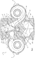
- figure 1 shows a section through a pump housing 2 of a double pump assembly 1 of a first embodiment along a radial plane perpendicular to the two pump axes. The other components of the double pump unit 1 are not shown.
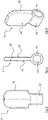
- Figures 2 to 4 show a flap 9 used in the double pump unit 1 in different views.
- the double pump unit 1 has two centrifugal pumps driven by an electric motor, the pump axes of which are parallel in this embodiment.
- the centrifugal pumps can be designed as glandless pumps, so that the respective motor shaft forms the pump shaft at the same time.
- the two pump shafts each carry an impeller at their respective ends, which is arranged in a pump chamber 3, 4 in each case.
- the two pump chambers 3, 4 are in figure 1 shown. You are part of the pump housing 2, so that the pump housing 2 is a common component of both centrifugal pumps.
- the pump housing 2 has an inlet opening 17 which leads into an inlet channel 16 which is radial to the pump axes and which is divided into two suction channels 13, 14, of which one suction channel 13, 14 leads in the axial direction into one of the two pump chambers 3, 4 flows.
- One of the impellers is arranged in the respective mouth opening.
- a pressure channel 5 , 6 in the pump housing 2 of each of the two pump chambers 3 , 4 opens into a common valve chamber 7 , which merges into an outlet channel 8 .
- the outlet channel 8 has an outlet opening 13, which is located in the so-called pressure port.
- the inlet opening 17 is located in a so-called suction nozzle.
- the suction and pressure connections are aligned coaxially here, so that the double pump unit 1 forms a so-called inline pump, which is connected to a hydraulic pipe system with the suction and pressure connections.
- a flap 9 is arranged, which is also referred to as a double pump flap. It is held pivotably with a holding section 10 in a receiving space 11 of the pump housing 2 and can thereby selectively close the first or second pressure channel 5, 6.
- the receiving space 11 is different from the pressure channels 5, 6. Consequently, the holding section 10 is not flowed against.
- the receiving space 11 opens to the flap space 7.
- the flap 9 is held in the receiving space 11 in a floating manner. In comparison to the prior art, the flap 9 is not mounted on a shaft that extends through the receiving space 11 . Consequently, the flap 9 is held without waves, which means that the holding section 10 is not stationary relative to the pump housing 2 . Thus, the position of the axis about which the flap 9 can be pivoted can be changed relative to the pump housing 2 .
- the all-round play is achieved in that the outer dimensions of the holding section 10 are smaller in each spatial direction than the inner dimensions of the receiving space 11.
- this embodiment variant has a holding section 10 with a circular cross section, with the receiving space 11 also having a circular cross section. Consequently, in order to achieve play on all sides, the outer diameter of the holding section 10 is smaller than the inner diameter of the receiving space 11, for example by 5 mm, so that there is a play of 2.5 mm.
- This has the advantage that the inner surface of the receiving space, which is very rough due to the production of the pump housing from cast metal using a sand core, does not have to be machined.
- the respective sealing surface 25 of the pump housing 2 around the opening of the corresponding pressure channel 5, 6 in the flap chamber 7 is dimensioned laterally sufficiently large so that the flap 9 also completely closes the corresponding pressure channel 5, 6 through its contact with the sealing surface 25 when because of its mobility, it is sometimes positioned higher, sometimes further down, sometimes further to the right or sometimes further to the left.
- the receiving space 11 opens towards the flap space 7 via an opening 12 through which the holding section 10 is inserted into the receiving space 10 .
- the opening 12 is delimited laterally by a web 23, 24 each, so that the opening 12 lies between these two webs 23, 24.
- a first of these webs 23 is formed between the first pressure channel 5 and the receiving space 11
- the second of these webs 24 is formed between the second pressure channel 6 and the receiving space 11 .
- the end faces of these webs 23, 24 each form part of the sealing surface 25 which surrounds the orifice in the form of a ring.
- the sealing surface 25 forms, so to speak, a stop for the flap 9.
- the opening 12 is narrower than the holding section 10 or the holding section 10 is wider than the opening 12, so that it engages behind the two webs 23, 24.
- the holding section 11 is elastic in such a way that it can be compressed to a width which is less than or equal to the width of the opening 12 .
- the holding portion 10 is made of an elastic material, for example EPDM, preferably with a hardness between 60 to 90 Shor.
- the holding section 10 is designed as a hollow body. In other words, it consists of an annular wall which encloses a cavity 19 which is in particular cylindrical. The holding section 10 is thus deformed by a movement of the ring-shaped wall into the cavity 19 .
- the wall thickness can be thinner or thicker.
- the material may be harder if the wall thickness is thinner, or the wall thickness may be thicker if the material is softer.
- the wall thickness is preferably between 3 and 5 mm.
- the flap 9 is inserted through the outlet opening 13 of the outlet channel 8 , which is aligned with the opening 12 of the receiving space 11 in order to simplify this.
- a pair of pliers in particular needle-nose pliers, can be used for insertion. If the flap 9 with the holding section 10 is increasingly pressed against the webs 23, 24, its annular wall deviates inwards into the cavity 19 so that its width is reduced and it can slide past the webs 23, 24 into the receiving space 11 , where the wall relaxes back to its original circular shape.
- the flap 9 can also be pulled out of the receiving space 11 again in the same way.
- FIG figures 2 to 4 show the flap 9 according to FIG figure 1 in front ( 2 ), Pages- ( 3 ) and perspective view ( 4 ).
- the flap 9 consists of a flap body 18 and the holding section 10. These are cast here in one piece from the same material.
- the flap body 18 is tongue-shaped in that of a plate with a flap front 26 and a flap rear 27 which are parallel to each other. The outer edge area of the flap front 26 and the
- the rear side 27 of the flap forms a sealing surface on the flap side in order to come into contact with the respective sealing surface 25 on the pump housing 2 side.
- the width of the flap body 18 is greater than the axial length of the holding portion 10, so that the flap body 18 projects axially on both sides relative to the holding portion 10, such as Figures 2 and 4 illustrate.
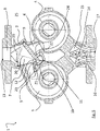
- FIG 5 show a pump housing 2 according to a second embodiment of a double pump unit according to the invention 1. It differs from the first variant essentially in the position and shape of the receiving space 10 and in the shape of the flap 9, which is in the Figures 6 to 8 is shown. Furthermore, the suction and pressure connections are formed by flanges.
- the receiving space 11 is also symmetrical, it has first and second side wings 21, 22 which are opposite one another with respect to an axis of symmetry 20 and form approximately a heart shape.
- the holding section 10 is shaped in such a way that when the first pressure channel 5 is closed it predominantly lies in the second side wing 22 and when the second pressure channel 6 is closed it predominantly lies in the first side wing 21 .
- the first pressure channel 5 and the second side wing 22, on the one hand, and the second pressure channel 6 and the first side wing 21, on the other hand, are each on opposite sides of the axis of symmetry 20 of the receiving space 11.
- the holding section 10 has a width (B) which is greater than its height H, see in particular 7 .
- the cavity 19 has the cross section of an elongated hole.
- Another difference between the flap 9 and the first embodiment is that the holding section 10 has the same width as the flap body 18 .
- the wall of the receiving space 11 is free of passages to the outside, so that there is no risk of leakage as a result of the flap 9 used.
- the invention also includes any changes, alterations or modifications of exemplary embodiments which have the exchange, addition, alteration or omission of elements, components, method steps, values or information as their subject matter, as long as the basic idea according to the invention is retained, regardless of whether the change, alteration, or modifications improves or degrades an embodiment.
Landscapes
- Engineering & Computer Science (AREA)
- Mechanical Engineering (AREA)
- General Engineering & Computer Science (AREA)
- Structures Of Non-Positive Displacement Pumps (AREA)
Abstract
Description
- Die Erfindung betrifft ein Doppelpumpenaggregat umfassend eine erste und eine zweite Kreiselpumpe mit einem gemeinsamen Pumpengehäuse, in dem je eine Pumpenkammer der ersten und zweiten Kreiselpumpe ausgebildet ist, von denen jeweils ein Druckkanal in einen gemeinsamen Klappenraum mündet, der in einen gemeinsamen Ausgangskanal übergeht und in dem eine Klappe angeordnet ist, die mit einem Halteabschnitt in einem Aufnahmeraum des Pumpengehäuses schwenkbar gehalten ist und wahlweise den einen oder anderen Druckkanal verschließt.
- Doppelpumpenaggregate dieser Bauart sind allgemein bekannt, beispielsweise aus den deutschen Patentanmeldungen
DE19511170A1 oderDE102014006258 A1 . Die Klappe, im Fachjargon auch Doppelpumpenklappe genannt, ist dabei schwenkbar auf einer Welle in Gestalt eines Stifts gelagert, der von außen in dem Pumpengehäuse montiert ist. Sowohl der Stift als auch das Pumpengehäuse sind hierfür speziell bearbeitet. So hat das Pumpengehäuse eine spezielle, zur Außenwelt offene Gewindebohrung, durch die der Stift in das Pumpengehäuse eingeführt ist. Der Stift hat wiederum an einem axialen Ende ein Außengewinde, mit dem er in die Gewindebohrung im Pumpengehäuse eingeschraubt ist. Um die Dichtheit zu erreichen, ist das Gewinde selbstdichtend, außerdem noch mit einem Kleber in der Gewindebohrung verklebt. Zusätzlich ist die Gewindebohrung mit einem Stopfen verschlossen. Es versteht sich von selbst, dass die Herstellung dieser Lagerung für die Doppelpumpenklappe technisch aufwändig ist. Ferner besteht auf Grund der Gewindebohrung im Pumpengehäuse im Hinblick auf die lange Lebensdauer einer Doppelpumpe stets auch ein gewisses, wenn auch minimales, Leckagerisiko. - Schließlich ist auch die Montage der Doppelpumpenklappe im Pumpengehäuse mühsam und schwierig, da sie zunächst durch den engen Ausgangskanal in den Klappenraum eingeführt werden muss, anschließend mit dem Hohlprofil ihres Einsetzendes fluchtend mit der Gewindebohrung ausgerichtet und so gehalten werden muss, um in diesem Haltezustand den Stift in das Hohlprofil einzuführen.
- Aufgabe der vorliegenden Erfindung ist es, die genannten Nachteile zu überwinden und ein Doppelpumpenaggregat mit einem Pumpengehäuse bereitzustellen, in dem die Klappe auf einfache Weise und ohne zusätzliche Bauteile montiert werden kann.
- Diese Aufgabe wird durch ein Doppelpumpenaggregat mit den Merkmalen des Anspruchs 1 gelöst. Vorteilhafte Weiterbildungen sind in den Unteransprüchen angegeben und werden nachfolgend erläutert.
- Erfindungsgemäß ist vorgesehen, dass die Klappe mit dem Halteabschnitt wellenlos schwimmend in dem Aufnahmeraum gehalten ist. Mit anderen Worten sitzt der Halteabschnitt locker im Aufnahmeraum. Es gibt somit keine Welle, um die die Klappe schwenkbar ist. Die geometrische Achse, um die die Klappe geschwenkt werden kann, ist nicht wie im Stand der Technik ortsfest, sondern vielmehr relativ zum Pumpengehäuse in ihrer Lage veränderlich. Die Klappe ist also um eine lageveränderliche Achse schwenkbar. Zusätzlich besteht ein allseitiges Spiel um den Halteabschnitt, welches eine Relativbewegung der Klappe zum Pumpengehäuse in alle Raumrichtungen ermöglicht. Die schwimmende Halterung führt bereits aufgrund des Spiels zu einer höheren Beweglichkeit der Klappe. Zusätzlich ist die Beweglichkeit infolge der fehlenden Welle erhöht, weil diese beim Schwenken der Klappe stets einen Reibungswiderstand bildete. Der Aufnahmeraum ist von den Druckkanälen verschieden. Folglich wird der Halteabschnitt nicht angeströmt.
- Ein weiterer Vorteil des Spiels um den Halteabschnitt besteht darin, dass die Innenwand des Aufnahmeraums nicht nachbearbeitet werden muss. Sie kann vielmehr herstellungsbedingt rau bleiben. So kann das Pumpengehäuse beispielsweise aus Grauguss unter Verwendung eines verlorenen Formkerns aus Sand für die Ausbildung des Aufnahmeraums hergestellt werden, was im Allgemeinen zu sehr rauen Innenflächen mit Unebenheiten führt. Für die erfindungsgemäße schwimmende Lagerung ist dies jedoch unerheblich.
- Die Klappe kann somit weiterhin ungehindert wahlweise den einen oder anderen Druckkanal verschließen, jedoch bedarf es zu ihrer Halterung keiner zusätzlichen Komponenten wie der separaten Welle bzw. des Stifts, einem Kleber oder einem Stopfen zum Verschluss der Bohrung im Pumpengehäuse. Auf ebendiese Bohrung kann außerdem verzichtet werden. Somit entfallen bei dem erfindungsgemäßen Doppelpumpenaggregat Herstellungs- und Bearbeitungsschritte, insbesondere am Pumpengehäuse, wodurch der Herstellungsprozess vereinfacht wird. Gleichzeitig gibt es aufgrund der fehlenden Bohrung kein Leckagerisiko mehr.
- In einer Ausführungsvariante kann sich der Aufnahmeraum zum Klappenraum hin über eine Öffnung öffnen, die schmaler als der Halteabschnitt ist. Um die Klappe in den Aufnahmeraum einzusetzen kann der Halteabschnitt derart elastisch sein, dass er auf eine Breite stauchbar ist, die kleiner gleich der Breite der Öffnung ist. Mit anderen Worten wird der Halteabschnitt beim Einsetzen der Klappe in den Aufnahmeraum zusammengedrückt/ gequetscht, um durch die Öffnung hindurch zu gelangen und kehrt nach der Überwindung der Öffnung in den ohne Kraftbeanspruchung vorliegenden, natürlichen Formzustand zurück, so dass er die Öffnung hintergreift. Auf diese Weise wird ein loser Formschluss realisiert. Diese Ausführungsvariante ermöglicht nicht nur ein einfaches und schnelles Montieren der Klappe im Pumpengehäuse. Die Klappe ist außerdem sicher im Aufnahmeraum gehalten und kann leicht wieder entfernt bzw. der Halteabschnitt wieder aus dem Aufnahmeraum herausgezogen werden, da der Formschluss leicht wieder lösbar ist. Beim Herausziehen wird der Halteabschnitt erneut gestaucht bzw. zusammengedrückt, so dass er die schmalere Öffnung wieder überwinden kann.
- Für das Einsetzen der Klappe ist kein besonderes Werkzeug erforderlich. Gegebenenfalls kann eine einfache Spitzzange verwendet werden, wenn die Hand nicht durch die Ausgangsöffnung des Ausgangskanals, d.h. nicht durch den Druckstutzen passt. Um das Einsetzen weiter zu erleichtern, kann die Öffnung zum Aufnahmeraum in einer Flucht mit der Ausgangsöffnung des Ausgangskanals liegt.
- Um die Elastizität des Halteabschnitts zu erhalten, kann in einer Ausführungsvariante vorgesehen sein, dass der Halteabschnitt aus einem elastischen Material hergestellt ist, insbesondere einem Material, das so weich ist, dass es selbst bei einer massiven Ausbildung des Halteabschnitts, d.h. bei einem Halteabschnitt aus Vollmaterial, ausreichend gestaucht werden kann, um die Öffnung zum Aufnahmeraum zu überwinden.
- Vorzugsweise ist der Halteabschnitt durch einen Hohlkörper gebildet, insbesondere einem Hohlprofil. Dies bewirkt ebenfalls eine Elastizität des Halteabschnitts, da sich dieser leichter verformen lässt, sodass das Material nicht so weich sein muss wie im Falle eines Halteabschnitts aus Vollmaterial.
- In einer Ausführungsvariante kann der Querschnitt des Halteabschnitts und des Aufnahmeraums jeweils kreisförmig sein. Diese kreisrunde Form hat den Vorteil, dass selbst wenn sich mit der Zeit Feststoffe im Aufnahmeraum ablagern sollte, die Klappe mit ihrem Halteabschnitt in jedem Schwenkwinkel weiterhin gut über diese Feststoffablagerungen hinweggleitet.
- Alternativ kann der Halteabschnitt auch oval oder in Form einer "0" ausgebildet sein. Ferner muss er nicht zwingend geschlossen sein. So kommen beispielsweise auch eine C-Form, T-Form oder V-Form in Frage, solange die Öffnung zum Aufnahmeraum vom Halteabschnitt hintergriffen wird.
- Von Vorteil ist es, wenn der Halteabschnitt allseitig mindestens ein Spiel von 1 mm aufweist. Im Falle einer kreisrunden Form weist der Aufnahmeraum dann einen Innendurchmesser auf, der mindestens 2mm größer ist, als der Außendurchmesser des Halteabschnitts. Ein derart großes Spiel hat den Vorteil, dass Feststoffpartikel, die sich mit der Zeit am Boden des Aufnahmeraums ansammeln können, die Beweglichkeit der Klappe nicht beeinträchtigen.
- Gemäß einer Ausführungsvariante kann Aufnahmeraum annährend symmetrisch sein und einen ersten und zweiten Seitenflügel aufweisen, wobei der Halteabschnitt derart geformt ist, dass er beim Verschließen des einen Druckkanals zumindest überwiegend in dem zweiten Seitenflügel einliegt und beim Verschließen des anderen Druckkanals zumindest überwiegend in dem ersten Seitenflügel einliegt, und sich der eine Druckkanal und der zweite Seitenflügel einerseits sowie der andere Druckkanal und der erste Seitenflügel andererseits jeweils auf gegenüberliegenden Seiten einer Symmetrieachse des Aufnahmeraums befinden. Mit einer derartigen Anordnung wird ein Höchstmaß an Flexibilität für die Geometrie des Pumpengehäuses geschaffen. Beispielsweise kann der genannte Aufnahmeraum mit den Seitenflügeln in Richtung zum Klappenraum schmaler sein, als in Richtung der Seitenflügel. So kann die erfindungsgemäße schwimmende Halterung auch bei Pumpengehäusen zum Einsatz kommen, bei denen eine im Querschnitt kreisrunde Ausführung des Aufnahmeraums und des Halteabschnitts aufgrund der Lage der Pumpenkammern und/ oder ihrer Druckkanäle und/ oder aufgrund des erforderlichen Schwenkwinkels (Lage und Öffnungswinkel) der Klappe nicht geht.
- Der Halteabschnitt kann im Querschnitt betrachtet eine Breite aufweisen, die größer ist, als seine Höhe. Eine solche Klappe kann vorteilhafterweise in einem Aufnahmeraum einliegen, der in Richtung zum Klappenraum schmaler ist, als in Richtung seiner Seitenflügel.
- Um eine Leckagegefahr vollkommen auszuschließen, kann die Wandung des Aufnahmeraums frei von Durchgängen, insbesondere Bohrungen nach außen sein.
- Eine besonders Einfache Herstellung der Klappe wird erreicht, wenn der Halteabschnitt einstückig mit einem Klappenkörper ist, der den einen oder anderen Druckkanal verschließt. Insbesondere können Halteabschnitt und Klappenkörper aus demselben Material in einem Guss hergestellt sein. Es besteht jedoch ebenfalls die Möglichkeit, den Klappenkörper separat zu fertigen und anschließend mit dem Halteabschnitt zusammen zu fügen, beispielsweise mittels Formschluss und/ oder durch eine Klebeverbindung. Dies hat den Vorteil, dass unterschiedliche Materialen für den Klappenkörper und den Halteabschnitt verwendet werden können. Der Formschluss kann z.B. in der Art eines Schwalbenschwanzes erfolgen.
- Weitere Merkmale, Eigenschaften, Wirkungen und Vorteile der Erfindung werden nachfolgend anhand von Ausführungsbeispielen und der beigefügten Figuren näher erläutert. Die in den Figuren enthaltenen Bezugszeichen behalten von Figur zu Figur ihre Bedeutung. In den Figuren bezeichnen Bezugszeichen stets dieselben oder äquivalente Komponenten, Bereiche, Richtungs- oder Ortsangaben.
- Es sei darauf hingewiesen, dass im Rahmen der vorliegenden Beschreibung die Begriffe "aufweisen", "umfassen" oder "beinhalten" keinesfalls das Vorhandensein weiterer Merkmale ausschließen. Ferner schließt die Verwendung des unbestimmten Artikels bei einem Gegenstand nicht dessen Plural aus. Es zeigen:
- Fig. 1:
- einen radialen Querschnitt durch ein Pumpengehäuse eines ersten erfindungsgemäßen Doppelpumpenaggregats
- Fig. 2:
- eine Vorderansicht der Klappe im Pumpengehäuse nach
Figur 1 - Fig. 3:
- eine Seitenansicht der Klappe im Pumpengehäuse nach
Figur 1 - Fig. 4:
- eine perspektivische Ansicht der Klappe im Pumpengehäuse nach
Figur 1 - Fig. 5:
- einen radialen Querschnitt durch ein Pumpengehäuse eines zweiten erfindungsgemäßen Doppelpumpenaggregats
- Fig. 6:
- eine Vorderansicht der Klappe im Pumpengehäuse nach
Figur 5 - Fig. 7:
- eine Seitenansicht der Klappe im Pumpengehäuse nach
Figur 5 - Fig. 8:
- eine perspektivische Ansicht der Klappe im Pumpengehäuse nach
Figur 5 -
Figur 1 zeigt einen Schnitt durch ein Pumpengehäuse 2 eines Doppelpumpenaggregats 1 einer ersten Ausführungsvariante entlang einer Radialebene senkrecht zu den beiden Pumpenachsen gemäß. Die weiteren Komponenten des Doppelpumpenaggregats 1 sind nicht dargestellt.Figuren 2 bis 4 zeigen eine in dem Doppelpumpenaggregat 1 verwendete Klappe 9 in verschiedenen Ansichten. - Das Doppelpumpenaggregat 1 besitzt zwei elektromotorisch angetrieben Kreiselpumpen, deren Pumpenachsen in dieser Ausführungsvariante parallel liegen. Die Kreiselpumpen können als Nassläuferpumpen ausgestaltet sein, so dass die jeweilige Motorwelle gleichzeitig die Pumpenwelle bildet. Die beiden Pumpenwellen tragen an ihrem jeweiligen Ende jeweils ein Laufrad, das in jeweils einer Pumpenkammer 3, 4 angeordnet ist. Die beiden Pumpenkammern 3, 4, sind in
Figur 1 dargestellt. Sie sind Teil des Pumpengehäuse 2, so dass das Pumpengehäuse 2 ein gemeinsames Bauteil beider Kreiselpumpen ist. - Das Pumpengehäuse 2 weist eine Eingangsöffnung 17 auf, die in einen radial zu den Pumpenachsen liegenden Eingangskanal 16 führt, welcher sich in zwei Saugkanäle 13, 14 aufteilt, von denen jeweils ein Saugkanal 13, 14 in axialer Richtung in eine der beiden Pumpenkammern 3, 4 mündet. In der jeweiligen Mündungsöffnung ist jeweils eines der Laufräder angeordnet. Von den beiden Pumpenkammern 3, 4 mündet jeweils ein Druckkanal 5, 6 im Pumpengehäuse 2 in einen gemeinsamen Klappenraum 7, welcher in einen Ausgangskanal 8 übergeht. Der Ausgangskanal 8 hat eine Ausgangsöffnung 13, die in dem sogenannten Druckstutzen liegt. In entsprechender Weise liegt die Eingangsöffnung 17 in einem sogenannten Saugstutzen. Saug- und Druckstutzen sind hier koaxial ausgerichtet, so dass das Doppelpumpenaggregat 1 eine sogenannte Inline-Pumpe bildet, die mit dem Saugund Druckstutzen an ein hydraulisches Rohrleitungssystem angeschlossen wird.
- In dem Klappenraum 7 ist eine Klappe 9 angeordnet, die auch als Doppelpumpenklappe bezeichnet wird. Sie ist mit einem Halteabschnitt 10 in einem Aufnahmeraum 11 des Pumpengehäuses 2 schwenkbar gehalten und kann dadurch wahlweise den ersten oder zweiten Druckkanal 5, 6 verschließen. Der Aufnahmeraum 11 ist von den Druckkanälen 5, 6 verschieden. Folglich wird der Halteabschnitt 10 nicht angeströmt. Der Aufnahmeraum 11 öffnet sich zum Klappenraum 7.
- Die Halterung der Klappe 9 im Aufnahmeraum 11 erfolgt schwimmend. Im Vergleich zum Stand der Technik gibt es also keine Lagerung der Klappe 9 auf einer Welle, die sich durch den Aufnahmeraum 11 erstreckt. Folglich ist die Klappe 9 wellenlos gehalten, was dazu führt, dass der Halteabschnitt 10 relativ zum Pumpengehäuse 2 nicht ortsfest ist. Somit ist die Achse, um die die Klappe 9 geschwenkt werden kann, relativ zum Pumpengehäuse 2 in ihrer Lage veränderlich.
- Es besteht außerdem ein allseitiges Spiel um den Halteabschnitt 10, welches eine Relativbewegung der Klappe 9 zum Pumpengehäuse 2 in alle Raumrichtungen ermöglicht. Das Spiel ist in
Figur 1 erkennbar, wobei sich die Klappe 9 allerdings in dieser das Doppelpumpenaggregat 1 in seinem betriebslosen Zustand zeigenden Darstellung aufgrund ihres Eigengewichts am Grund des Aufnahmeraums 11 abstützt. Es sei betont, dass dieser Kontakt zwischen Halteabschnitt 11 und Pumpengehäuse 2 aufgrund der fehlenden Fixierung der Klappe 9 im Pumpengehäuse 2 dennoch als Spiel verstanden wird, da die Klappe 7 jedenfalls die Möglichkeit besitzt, aufzuschwimmen. - Das allseitige Spiel wird dadurch erreicht, dass die Außenabmessungen des Halteabschnitts 10 in jede Raumrichtung kleiner sind, als die Innenabmessungen des Aufnahmeraums 11. Wie in
Figur 1 ersichtlich ist, weist diese Ausführungsvariante einen im Querschnitt kreisrunden Halteabschnitt 10 auf, wobei auch der Aufnahmeraum 11 im Querschnitt kreisförmig ist. Folglich ist zur Erreichung des allseitigen Spiels der Außendurchmesser des Halteabschnitts 10 kleiner als der Innendurchmesser des Aufnahmeraums 11, beispielhaft um 5mm, so dass ein Spiel von 2,5mm besteht. Dies hat den Vorteil, das die Innenfläche des Aufnahmeraums, welche infolge der Herstellung des Pumpengehäuses aus Metallguss unter Verwendung eines Sandkerns sehr rau ist, nicht bearbeitet werden muss. Gleichzeitig ist die jeweilige Dichtfläche 25 des Pumpengehäuses 2 um die Mündungsöffnung des entsprechenden Druckkanals 5, 6 im Klappenraum 7 herum lateral ausreichend groß dimensioniert, damit die Klappe 9 durch ihre Anlage an der Dichtfläche 25 den entsprechenden Druckkanal 5, 6 auch dann vollständig verschließt, wenn sie infolge ihrer Beweglichkeit mal weiter oben, mal weiter unten, mal weiter rechts oder mal weiter links positioniert ist. - Der Aufnahmeraum 11 öffnet sich zum Klappenraum 7 hin über eine Öffnung 12, durch die der Halteabschnitt 10 in den Aufnahmeraum 10 eingesetzt ist. Die Öffnung 12 ist seitlich von je einem Steg 23, 24 begrenzt, so dass die Öffnung 12 zwischen diesen beiden Stegen 23, 24 liegt. Ein erster dieser Stege 23 ist zwischen dem ersten Druckkanal 5 und dem Aufnahmeraum 11, der zweite dieser Stege 24 zwischen dem zweiten Druckkanal 6 und dem Aufnahmeraum 11 ausgebildet. Die Stirnseiten dieser Stege 23, 24 bilden jeweils einen Teil der Dichtfläche 25, die die Mündungsöffnung ringförmig umgibt. Die Dichtfläche 25 bildet sozusagen einen Anschlag für die Klappe 9.
- Damit die Klappe 9 mit ihrem Halteabschnitt 10 im Aufnahmeraum 11 verbleibt, ist die Öffnung 12 schmaler als der Halteabschnitt 10 bzw. der Halteabschnitt 10 breiter als die Öffnung 12, so dass er die beiden Stege 23, 24 hintergreift. Um sein Einsetzen durch die Öffnung 12 zu gewährleisten, ist der Halteabschnitt 11 derart elastisch, dass er auf eine Breite stauchbar ist, die kleiner gleich der Breite der Öffnung 12 ist. Dies ist in der Ausführungsvariante gemäß
Figur 1 dadurch erreicht, dass der Halteabschnitt 10 aus einem elastischen Material hergestellt ist, beispielsweise aus EPDM, vorzugsweise mit einer Härte zwischen 60 bis 90 Shor. Zusätzlich ist der Halteabschnitt 10 als Hohlkörper ausgebildet. Mit anderen Worten besteht er aus einer ringförmigen Wand, die einen insbesondere zylindrischen Hohlraum 19 einschließt. Eine Verformung des Halteabschnitts 10 erfolgt somit durch eine Bewegung der ringförmigen Wand in den Hohlraum 19 hinein. - Je nach Elastizität des Materials kann die Wanddicke schmaler oder dicker sein. Anders ausgedrückt darf das Material härter sein, wenn die Wandstärke geringer ist, oder die Wandstärke größer sein, wenn das Material weicher ist. Bevorzugt liegt die Wandstärke zwischen 3 und 5mm.
- Das Einsetzen der Klappe 9 erfolgt durch die Ausgangsöffnung 13 des Ausgangskanals 8 hindurch, welche um dies zu vereinfachen in einer Flucht mit der Öffnung 12 des Aufnahmeraums 11 liegt. Zum Einsetzen kann eine Zange, insbesondere eine Spitzzange verwendet werden. Wird die Klappe 9 mit dem Halteabschnitt 10 zunehmend gegen die Stege 23, 24 gedrückt, weicht dessen ringförmige Wand nach Innen in den Hohlraum 19 aus, so dass sich seine Breite reduziert und er an den Stegen 23, 24 vorbei in den Aufnahmeraum 11 gleiten kann, wo die Wand wieder in ihre ursprünglichen Kreisform relaxiert. In gleicher Weise kann die Klappe 9 auch wieder aus dem Aufnahmeraum 11 herausgezogen werden.
-
Figuren 2 bis 4 zeigen die Klappe 9 gemäßFigur 1 in Vorder- (Fig. 2 ), Seiten- (Fig. 3 ) und perspektivischer Ansicht (Fig. 4 ). Die Klappe 9 besteht aus einem Klappenkörper 18 und dem Halteabschnitt 10. Diese sind hier einstückig aus demselben Material gegossen. Der Klappenkörper 18 ist zungenartig geformt in der einer Platte mit einer Klappenvorderseite 26 und einer Klappenrückseite 27, die parallel zu einander liegen. Der äußere Randbereich der Klappenvorderseite 26 und der - Klappenrückseite 27 bilden eine klappenseitige Dichtfläche, um mit der jeweiligen Dichtfläche 25 seitens des Pumpengehäuses 2 in Anlage zu gelangen. Die Breite des Klappenkörpers 18 ist größer als die axiale Länge des Halteabschnitts 10, so dass der Klappenkörper 18 beidseits axial gegenüber dem Halteabschnitt 10 vorsteht, wie
Figuren 2 und 4 veranschaulichen. -
Figur 5 zeigen ein Pumpengehäuse 2 gemäß einer zweiten Ausführungsvariante eines erfindungsgemäßen Doppelpumpenaggregats 1. Es unterscheidet sich von der ersten Variante im Wesentlichen in der Lage und Form des Aufnahmeraums 10 und in der Form der Klappe 9, die in denFiguren 6 bis 8 gezeigt ist. Ferner sind Saugund Druckstutzen durch Flansche gebildet. - Der Aufnahmeraum 11 gemäß dieser zweiten Ausführungsvariante ist zwar ebenfalls symmetrisch, er besitzt jedoch einen ersten und zweiten Seitenflügel 21, 22, die sich bezogen auf eine Symmetrieachse 20 gegenüberliegen und annährend eine Herzform bilden. Der Halteabschnitt 10 ist derart geformt, dass er beim Verschließen des ersten Druckkanals 5 überwiegend in dem zweiten Seitenflügel 22 einliegt und beim Verschließen des zweiten Druckkanals 6 überwiegend in dem ersten Seitenflügel 21 einliegt. Dabei befinden sich der erste Druckkanal 5 und der zweite Seitenflügel 22 einerseits sowie der zweite Druckkanal 6 und der erste Seitenflügel 21 andererseits jeweils auf gegenüberliegenden Seiten der Symmetrieachse 20 des Aufnahmeraums 11.
- Der Halteabschnitt 10 weist im Querschnitt betrachtet eine Breite (B) auf, die größer ist, als seine Höhe H, vergleiche hierzu insbesondere
Fig. 7 . Der Hohlraum 19 hat insgesamt den Querschnitt eines Langlochs. Ein weiterer Unterschied der Klappe 9 gegenüber der ersten Ausführungsvariante besteht darin, dass der Halteabschnitt 10 eine identische Breite wie der Klappenkörper 18 aufweist. - In beiden Ausführungsvarianten ist die Wandung des Aufnahmeraums 11 frei von Durchgängen nach außen, so dass infolge der eingesetzten Klappe 9 keine Leckagegefahr besteht.
- Es sei darauf hingewiesen, dass die vorstehende Beschreibung lediglich beispielhaft zum Zwecke der Veranschaulichung gegeben ist und den Schutzbereich der Erfindung keineswegs einschränkt. Merkmale der Erfindung, die als "kann", "beispielhaft", "bevorzugt", "optional", "ideal", "vorteilhaft", "gegebenenfalls", "geeignet" oder dergleichen angegeben sind, sind als rein fakultativ zu betrachten und schränken ebenfalls den Schutzbereich nicht ein, welcher ausschließlich durch die Ansprüche festgelegt ist. Soweit in der vorstehenden Beschreibung Elemente, Komponenten, Verfahrensschritte, Werte oder Informationen genannt sind, die bekannte, naheliegende oder vorhersehbare Äquivalente besitzen, werden diese Äquivalente von der Erfindung mit umfasst. Ebenso schließt die Erfindung jegliche Änderungen, Abwandlungen oder Modifikationen von Ausführungsbeispielen ein, die den Austausch, die Hinzunahme, die Änderung oder das Weglassen von Elementen, Komponenten, Verfahrensschritte, Werten oder Informationen zum Gegenstand haben, solange der erfindungsgemäße Grundgedanke erhalten bleibt, ungeachtet dessen, ob die Änderung, Abwandlung oder Modifikationen zu einer Verbesserung oder Verschlechterung einer Ausführungsform führt.
- Obgleich die vorstehende Erfindungsbeschreibung eine Vielzahl körperlicher, unkörperlicher oder verfahrensgegenständlicher Merkmale in Bezug zu einem oder mehreren konkreten Ausführungsbeispiel(en) nennt, so können diese Merkmale auch isoliert von dem konkreten Ausführungsbeispiel verwendet werden, jedenfalls soweit sie nicht das zwingende Vorhandensein weiterer Merkmale erfordern. Umgekehrt können diese in Bezug zu einem oder mehreren konkreten Ausführungsbeispiel(en) genannten Merkmale beliebig miteinander sowie mit weiteren offenbarten oder nicht offenbarten Merkmalen von gezeigten oder nicht gezeigten Ausführungsbeispielen kombiniert werden, jedenfalls soweit sich die Merkmale nicht gegenseitig ausschließen oder zu technischen Unvereinbarkeiten führen.
-
- 1 Doppelpumpenaggregat
- 2 Pumpengehäuse
- 3 Erste Pumpenkammer
- 4 Zweite Pumpenkammer
- 5 Erster Druckkanal
- 6 Zweiter Druckkanal
- 7 Klappenraum
- 8 Ausgangskanal
- 9 Klappe
- 10 Halteabschnitt
- 11 Aufnahmeraum
- 12 Öffnung
- 13 Ausgangsöffnung
- 14 Erster Saugkanal
- 15 Zweiter Saugkanal
- 16 Eingangskanal
- 17 Eingangsöffnung
- 18 Klappenkörper
- 19 Hohlraum
- 20 Symmetrieachse
- 21 Erster Seitenflügel
- 22 Zweiter Seitenflügel
- 23 Erster Steg
- 24 Zweiter Steg
- 25 Dichtfläche
- 26 Klappenvorderseite
- 27 Klappenrückseite
Claims (12)
- Doppelpumpenaggregat (1) umfassend eine erste und eine zweite Kreiselpumpe mit einem gemeinsamen Pumpengehäuse (2), in dem je eine Pumpenkammer (3, 4) der ersten und zweiten Kreiselpumpe ausgebildet ist, von denen jeweils ein Druckkanal (5, 6) in einen gemeinsamen Klappenraum (7) mündet, der in einen Ausgangskanal (8) übergeht und in dem eine Klappe (9) angeordnet ist, die mit einem Halteabschnitt (10) in einem Aufnahmeraum (11) des Pumpengehäuses (2) schwenkbar gehalten ist und wahlweise den einen oder anderen Druckkanal (5, 6) verschließt, dadurch gekennzeichnet, dass die Klappe (9) wellenlos schwimmend in dem Aufnahmeraum (11) gehalten ist.
- Doppelpumpenaggregat (1) nach Anspruch 1, dadurch gekennzeichnet, dass die Klappe (9) um eine lageveränderliche Achse schwenkbar ist und ein allseitiges Spiel um den Halteabschnitt (10) besteht.
- Doppelpumpenaggregat (1) nach Anspruch 1 oder 2, dadurch gekennzeichnet, dass sich der Aufnahmeraum (11) zum Klappenraum (7) hin über eine Öffnung (12) öffnet, die schmaler als der Halteabschnitt (10) ist, und dass der Halteabschnitt (11) derart elastisch ist, dass er auf eine Breite stauchbar ist, die kleiner gleich der Breite der Öffnung (12) ist.
- Doppelpumpenaggregat (1) nach Anspruch 3, dadurch gekennzeichnet, dass die Öffnung (12) in einer Flucht mit der Ausgangsöffnung (13) des Ausgangskanals (8) liegt.
- Doppelpumpenaggregat (1) nach einem der vorherigen Ansprüche, dadurch gekennzeichnet, dass der Halteabschnitt (10) aus einem elastischen Material hergestellt ist.
- Doppelpumpenaggregat (1) nach einem der vorherigen Ansprüche, dadurch gekennzeichnet, dass der Halteabschnitt (10) durch einen Hohlkörper, insbesondere ein Hohlprofil gebildet ist.
- Doppelpumpenaggregat (1) nach einem der vorherigen Ansprüche, dadurch gekennzeichnet, dass der Querschnitt des Halteabschnitts (10) und des Aufnahmeraums (11) jeweils kreisförmig sind.
- Doppelpumpenaggregat (1) nach einem der vorherigen Ansprüche, dadurch gekennzeichnet, dass der Halteabschnitt (10) allseitig mindestens ein Spiel von 1mm aufweist.
- Doppelpumpenaggregat (1) nach einem der vorherigen Ansprüche, dadurch gekennzeichnet, dass Aufnahmeraum (11) annährend symmetrisch ist und einen ersten und zweiten Seitenflügel (21, 22) aufweist, und dass der Halteabschnitt (10) derart geformt ist, dass er beim Verschließen des einen Druckkanals (5) zumindest überwiegend in dem zweiten Seitenflügel (22) einliegt und beim Verschließen des anderen Druckkanals (6) zumindest überwiegend in dem ersten Seitenflügel (21) einliegt, wobei sich der eine Druckkanal (5) und der zweite Seitenflügel (22) einerseits sowie der andere Druckkanal (6) und der erste Seitenflügel (21) andererseits jeweils auf gegenüberliegenden Seiten einer Symmetrieachse (20) des Aufnahmeraums (11) befinden.
- Doppelpumpenaggregat (1) nach einem der vorherigen Ansprüche, dadurch gekennzeichnet, dass der Halteabschnitt (10) im Querschnitt betrachtet eine Breite (B) aufweist, die größer ist, als seine Höhe (H).
- Doppelpumpenaggregat (1) nach einem der vorherigen Ansprüche, dadurch gekennzeichnet, dass die Wandung des Aufnahmeraums (11) frei von Durchgängen nach außen ist.
- Doppelpumpenaggregat (1) nach einem der vorherigen Ansprüche, dadurch gekennzeichnet, dass der Halteabschnitt (10) einstückig mit einem den einen oder anderen Druckkanal (5, 6) verschließenden Klappenkörper (18) ist, insbesondere aus einem Guss mit diesem hergestellt ist.
Applications Claiming Priority (1)
| Application Number | Priority Date | Filing Date | Title |
|---|---|---|---|
| LU102816A LU102816B1 (de) | 2021-06-01 | 2021-06-01 | Doppelpumpenaggregat |
Publications (2)
| Publication Number | Publication Date |
|---|---|
| EP4098880A1 true EP4098880A1 (de) | 2022-12-07 |
| EP4098880B1 EP4098880B1 (de) | 2025-01-29 |
Family
ID=76829608
Family Applications (1)
| Application Number | Title | Priority Date | Filing Date |
|---|---|---|---|
| EP22165677.0A Active EP4098880B1 (de) | 2021-06-01 | 2022-03-30 | Doppelpumpenaggregat |
Country Status (2)
| Country | Link |
|---|---|
| EP (1) | EP4098880B1 (de) |
| LU (1) | LU102816B1 (de) |
Cited By (1)
| Publication number | Priority date | Publication date | Assignee | Title |
|---|---|---|---|---|
| LU503228B1 (de) | 2022-12-21 | 2024-06-21 | Wilo Se | Doppelpumpe mit Isolierverkleidung und zugehöriges Montageverfahren |
Citations (5)
| Publication number | Priority date | Publication date | Assignee | Title |
|---|---|---|---|---|
| DE2237108B1 (de) * | 1972-07-28 | 1973-02-15 | Klein, Schanzhn & Becker AG, 6710 Frankenthal | Doppelpumpenaggregat |
| DE19511170A1 (de) | 1995-03-28 | 1996-10-02 | Wilo Gmbh | Doppelpumpe mit übergeordneter Steuerung |
| DE102014006258A1 (de) | 2014-04-30 | 2015-11-05 | Wilo Se | Verfahren zur Regelung eines Pumpensystems und geregeltes Pumpensystem |
| EP3179110A1 (de) * | 2015-12-10 | 2017-06-14 | Wilo Se | Doppelpumpe |
| WO2019192984A1 (de) * | 2018-04-03 | 2019-10-10 | Nidec Gpm Gmbh | Hybridangetriebene doppelpumpe |
-
2021
- 2021-06-01 LU LU102816A patent/LU102816B1/de active
-
2022
- 2022-03-30 EP EP22165677.0A patent/EP4098880B1/de active Active
Patent Citations (5)
| Publication number | Priority date | Publication date | Assignee | Title |
|---|---|---|---|---|
| DE2237108B1 (de) * | 1972-07-28 | 1973-02-15 | Klein, Schanzhn & Becker AG, 6710 Frankenthal | Doppelpumpenaggregat |
| DE19511170A1 (de) | 1995-03-28 | 1996-10-02 | Wilo Gmbh | Doppelpumpe mit übergeordneter Steuerung |
| DE102014006258A1 (de) | 2014-04-30 | 2015-11-05 | Wilo Se | Verfahren zur Regelung eines Pumpensystems und geregeltes Pumpensystem |
| EP3179110A1 (de) * | 2015-12-10 | 2017-06-14 | Wilo Se | Doppelpumpe |
| WO2019192984A1 (de) * | 2018-04-03 | 2019-10-10 | Nidec Gpm Gmbh | Hybridangetriebene doppelpumpe |
Cited By (2)
| Publication number | Priority date | Publication date | Assignee | Title |
|---|---|---|---|---|
| LU503228B1 (de) | 2022-12-21 | 2024-06-21 | Wilo Se | Doppelpumpe mit Isolierverkleidung und zugehöriges Montageverfahren |
| EP4390140A1 (de) | 2022-12-21 | 2024-06-26 | Wilo Se | Doppelpumpe mit isolierverkleidung und zugehöriges montageverfahren |
Also Published As
| Publication number | Publication date |
|---|---|
| EP4098880B1 (de) | 2025-01-29 |
| LU102816B1 (de) | 2022-12-01 |
Similar Documents
| Publication | Publication Date | Title |
|---|---|---|
| DE4491977C1 (de) | Mehrstufige Strahlpumpeneinheit | |
| DE69713990T2 (de) | Axial belastbare Verbindungsanordnung | |
| EP0749378B1 (de) | Wischblatt | |
| DE60305236T2 (de) | Verbindungsvorrichtung zur Verbindung von zwei Rohren | |
| DE102020129491B3 (de) | Druckhalteventil für eine Luftfeder und Luftfeder umfassend das Druckhalteventil | |
| EP1911925B1 (de) | Rahmen für Fenster, Türen, Fassadenelemente und dergleichen | |
| LU102816B1 (de) | Doppelpumpenaggregat | |
| EP3759285A1 (de) | Kugelgelenk | |
| EP3212911B1 (de) | Abgasturbolader für eine brennkraftmaschine sowie verfahren zum herstellen eines abgasturboladers | |
| DE102006024841B4 (de) | Elktromagnetische Stellvorrichtung | |
| EP2928619B1 (de) | Spülschlauchgelenk, spülschlauchdrehvorrichtung und spüldüse | |
| DE102014217240A1 (de) | Doppelschließzylinder | |
| DE102007006871B4 (de) | Kugelsitzventil mit sich trichterförmig erweiterndem Ventilsitzkörper | |
| EP4390207B1 (de) | Kupplungsteil für eine hydraulikkupplung | |
| DE102024104315A1 (de) | Scharniervorrichtung | |
| EP0857901A2 (de) | Ventil | |
| DE10163785A1 (de) | Einrichtung zum Zusammenschalten mehrerer hydraulischer oder pneumatischer Komponenten, insbesondere mehrerer Elektromagnetventile | |
| DE102004032974B4 (de) | Klappenventil für die Abgasanlage eines Kraftfahrzeugs | |
| DE69107249T2 (de) | Verfahren zum Einziehen eines Kabels in ein Rohr und Vorrichtung zur Durchführung des Verfahens. | |
| DE102006050905A1 (de) | Zylinderschloss mit einem Schutz gegen Manipulation durch Schlageinwirkung | |
| DE102015118748B4 (de) | Axiales Magnetventil und Anker für ein axiales Magnetventil | |
| EP4116596B1 (de) | Doppelkreuzgelenk mit einer radial bewegbaren zentrierscheibe für die beide kreuzgelenke | |
| AT512893A4 (de) | Bauelement mit ineinandermündenden Hochdruckbohrungen | |
| EP1058797B1 (de) | Absperrschieber | |
| DE102017112551A1 (de) | Abgasklappenventil |
Legal Events
| Date | Code | Title | Description |
|---|---|---|---|
| PUAI | Public reference made under article 153(3) epc to a published international application that has entered the european phase |
Free format text: ORIGINAL CODE: 0009012 |
|
| STAA | Information on the status of an ep patent application or granted ep patent |
Free format text: STATUS: THE APPLICATION HAS BEEN PUBLISHED |
|
| AK | Designated contracting states |
Kind code of ref document: A1 Designated state(s): AL AT BE BG CH CY CZ DE DK EE ES FI FR GB GR HR HU IE IS IT LI LT LU LV MC MK MT NL NO PL PT RO RS SE SI SK SM TR |
|
| STAA | Information on the status of an ep patent application or granted ep patent |
Free format text: STATUS: REQUEST FOR EXAMINATION WAS MADE |
|
| 17P | Request for examination filed |
Effective date: 20230329 |
|
| RBV | Designated contracting states (corrected) |
Designated state(s): AL AT BE BG CH CY CZ DE DK EE ES FI FR GB GR HR HU IE IS IT LI LT LU LV MC MK MT NL NO PL PT RO RS SE SI SK SM TR |
|
| P01 | Opt-out of the competence of the unified patent court (upc) registered |
Effective date: 20230615 |
|
| GRAP | Despatch of communication of intention to grant a patent |
Free format text: ORIGINAL CODE: EPIDOSNIGR1 |
|
| STAA | Information on the status of an ep patent application or granted ep patent |
Free format text: STATUS: GRANT OF PATENT IS INTENDED |
|
| INTG | Intention to grant announced |
Effective date: 20241015 |
|
| GRAS | Grant fee paid |
Free format text: ORIGINAL CODE: EPIDOSNIGR3 |
|
| GRAA | (expected) grant |
Free format text: ORIGINAL CODE: 0009210 |
|
| STAA | Information on the status of an ep patent application or granted ep patent |
Free format text: STATUS: THE PATENT HAS BEEN GRANTED |
|
| AK | Designated contracting states |
Kind code of ref document: B1 Designated state(s): AL AT BE BG CH CY CZ DE DK EE ES FI FR GB GR HR HU IE IS IT LI LT LU LV MC MK MT NL NO PL PT RO RS SE SI SK SM TR |
|
| REG | Reference to a national code |
Ref country code: GB Ref legal event code: FG4D Free format text: NOT ENGLISH |
|
| REG | Reference to a national code |
Ref country code: CH Ref legal event code: EP |
|
| REG | Reference to a national code |
Ref country code: DE Ref legal event code: R096 Ref document number: 502022002742 Country of ref document: DE |
|
| REG | Reference to a national code |
Ref country code: IE Ref legal event code: FG4D Free format text: LANGUAGE OF EP DOCUMENT: GERMAN |
|
| REG | Reference to a national code |
Ref country code: NL Ref legal event code: MP Effective date: 20250129 |
|
| PG25 | Lapsed in a contracting state [announced via postgrant information from national office to epo] |
Ref country code: NL Free format text: LAPSE BECAUSE OF FAILURE TO SUBMIT A TRANSLATION OF THE DESCRIPTION OR TO PAY THE FEE WITHIN THE PRESCRIBED TIME-LIMIT Effective date: 20250129 |
|
| PG25 | Lapsed in a contracting state [announced via postgrant information from national office to epo] |
Ref country code: RS Free format text: LAPSE BECAUSE OF FAILURE TO SUBMIT A TRANSLATION OF THE DESCRIPTION OR TO PAY THE FEE WITHIN THE PRESCRIBED TIME-LIMIT Effective date: 20250429 |
|
| PG25 | Lapsed in a contracting state [announced via postgrant information from national office to epo] |
Ref country code: FI Free format text: LAPSE BECAUSE OF FAILURE TO SUBMIT A TRANSLATION OF THE DESCRIPTION OR TO PAY THE FEE WITHIN THE PRESCRIBED TIME-LIMIT Effective date: 20250129 |
|
| PG25 | Lapsed in a contracting state [announced via postgrant information from national office to epo] |
Ref country code: PL Free format text: LAPSE BECAUSE OF FAILURE TO SUBMIT A TRANSLATION OF THE DESCRIPTION OR TO PAY THE FEE WITHIN THE PRESCRIBED TIME-LIMIT Effective date: 20250129 |
|
| PG25 | Lapsed in a contracting state [announced via postgrant information from national office to epo] |
Ref country code: ES Free format text: LAPSE BECAUSE OF FAILURE TO SUBMIT A TRANSLATION OF THE DESCRIPTION OR TO PAY THE FEE WITHIN THE PRESCRIBED TIME-LIMIT Effective date: 20250129 |
|
| REG | Reference to a national code |
Ref country code: LT Ref legal event code: MG9D |
|
| PG25 | Lapsed in a contracting state [announced via postgrant information from national office to epo] |
Ref country code: NO Free format text: LAPSE BECAUSE OF FAILURE TO SUBMIT A TRANSLATION OF THE DESCRIPTION OR TO PAY THE FEE WITHIN THE PRESCRIBED TIME-LIMIT Effective date: 20250429 Ref country code: IS Free format text: LAPSE BECAUSE OF FAILURE TO SUBMIT A TRANSLATION OF THE DESCRIPTION OR TO PAY THE FEE WITHIN THE PRESCRIBED TIME-LIMIT Effective date: 20250529 |
|
| PG25 | Lapsed in a contracting state [announced via postgrant information from national office to epo] |
Ref country code: HR Free format text: LAPSE BECAUSE OF FAILURE TO SUBMIT A TRANSLATION OF THE DESCRIPTION OR TO PAY THE FEE WITHIN THE PRESCRIBED TIME-LIMIT Effective date: 20250129 |
|
| PG25 | Lapsed in a contracting state [announced via postgrant information from national office to epo] |
Ref country code: PT Free format text: LAPSE BECAUSE OF FAILURE TO SUBMIT A TRANSLATION OF THE DESCRIPTION OR TO PAY THE FEE WITHIN THE PRESCRIBED TIME-LIMIT Effective date: 20250529 Ref country code: LV Free format text: LAPSE BECAUSE OF FAILURE TO SUBMIT A TRANSLATION OF THE DESCRIPTION OR TO PAY THE FEE WITHIN THE PRESCRIBED TIME-LIMIT Effective date: 20250129 |
|
| PG25 | Lapsed in a contracting state [announced via postgrant information from national office to epo] |
Ref country code: GR Free format text: LAPSE BECAUSE OF FAILURE TO SUBMIT A TRANSLATION OF THE DESCRIPTION OR TO PAY THE FEE WITHIN THE PRESCRIBED TIME-LIMIT Effective date: 20250430 Ref country code: BG Free format text: LAPSE BECAUSE OF FAILURE TO SUBMIT A TRANSLATION OF THE DESCRIPTION OR TO PAY THE FEE WITHIN THE PRESCRIBED TIME-LIMIT Effective date: 20250129 |
|
| PG25 | Lapsed in a contracting state [announced via postgrant information from national office to epo] |
Ref country code: SE Free format text: LAPSE BECAUSE OF FAILURE TO SUBMIT A TRANSLATION OF THE DESCRIPTION OR TO PAY THE FEE WITHIN THE PRESCRIBED TIME-LIMIT Effective date: 20250129 |
|
| PG25 | Lapsed in a contracting state [announced via postgrant information from national office to epo] |
Ref country code: SM Free format text: LAPSE BECAUSE OF FAILURE TO SUBMIT A TRANSLATION OF THE DESCRIPTION OR TO PAY THE FEE WITHIN THE PRESCRIBED TIME-LIMIT Effective date: 20250129 |
|
| PG25 | Lapsed in a contracting state [announced via postgrant information from national office to epo] |
Ref country code: DK Free format text: LAPSE BECAUSE OF FAILURE TO SUBMIT A TRANSLATION OF THE DESCRIPTION OR TO PAY THE FEE WITHIN THE PRESCRIBED TIME-LIMIT Effective date: 20250129 |
|
| PG25 | Lapsed in a contracting state [announced via postgrant information from national office to epo] |
Ref country code: MC Free format text: LAPSE BECAUSE OF FAILURE TO SUBMIT A TRANSLATION OF THE DESCRIPTION OR TO PAY THE FEE WITHIN THE PRESCRIBED TIME-LIMIT Effective date: 20250129 |
|
| PG25 | Lapsed in a contracting state [announced via postgrant information from national office to epo] |
Ref country code: EE Free format text: LAPSE BECAUSE OF FAILURE TO SUBMIT A TRANSLATION OF THE DESCRIPTION OR TO PAY THE FEE WITHIN THE PRESCRIBED TIME-LIMIT Effective date: 20250129 Ref country code: CZ Free format text: LAPSE BECAUSE OF FAILURE TO SUBMIT A TRANSLATION OF THE DESCRIPTION OR TO PAY THE FEE WITHIN THE PRESCRIBED TIME-LIMIT Effective date: 20250129 |
|
| REG | Reference to a national code |
Ref country code: CH Ref legal event code: H13 Free format text: ST27 STATUS EVENT CODE: U-0-0-H10-H13 (AS PROVIDED BY THE NATIONAL OFFICE) Effective date: 20251023 |
|
| PG25 | Lapsed in a contracting state [announced via postgrant information from national office to epo] |
Ref country code: RO Free format text: LAPSE BECAUSE OF FAILURE TO SUBMIT A TRANSLATION OF THE DESCRIPTION OR TO PAY THE FEE WITHIN THE PRESCRIBED TIME-LIMIT Effective date: 20250129 |
|
| PG25 | Lapsed in a contracting state [announced via postgrant information from national office to epo] |
Ref country code: SK Free format text: LAPSE BECAUSE OF FAILURE TO SUBMIT A TRANSLATION OF THE DESCRIPTION OR TO PAY THE FEE WITHIN THE PRESCRIBED TIME-LIMIT Effective date: 20250129 |
|
| REG | Reference to a national code |
Ref country code: DE Ref legal event code: R097 Ref document number: 502022002742 Country of ref document: DE |
|
| PG25 | Lapsed in a contracting state [announced via postgrant information from national office to epo] |
Ref country code: LU Free format text: LAPSE BECAUSE OF NON-PAYMENT OF DUE FEES Effective date: 20250330 |
|
| PLBE | No opposition filed within time limit |
Free format text: ORIGINAL CODE: 0009261 |
|
| STAA | Information on the status of an ep patent application or granted ep patent |
Free format text: STATUS: NO OPPOSITION FILED WITHIN TIME LIMIT |
|
| REG | Reference to a national code |
Ref country code: BE Ref legal event code: MM Effective date: 20250331 |
|
| 26N | No opposition filed |
Effective date: 20251030 |
|
| PG25 | Lapsed in a contracting state [announced via postgrant information from national office to epo] |
Ref country code: BE Free format text: LAPSE BECAUSE OF NON-PAYMENT OF DUE FEES Effective date: 20250331 |
|
| PG25 | Lapsed in a contracting state [announced via postgrant information from national office to epo] |
Ref country code: CH Free format text: LAPSE BECAUSE OF NON-PAYMENT OF DUE FEES Effective date: 20250331 |
|
| PG25 | Lapsed in a contracting state [announced via postgrant information from national office to epo] |
Ref country code: IE Free format text: LAPSE BECAUSE OF NON-PAYMENT OF DUE FEES Effective date: 20250330 |
|
| PGFP | Annual fee paid to national office [announced via postgrant information from national office to epo] |
Ref country code: GB Payment date: 20260219 Year of fee payment: 5 |
|
| PGFP | Annual fee paid to national office [announced via postgrant information from national office to epo] |
Ref country code: DE Payment date: 20260219 Year of fee payment: 5 |
|
| PGFP | Annual fee paid to national office [announced via postgrant information from national office to epo] |
Ref country code: AT Payment date: 20260301 Year of fee payment: 5 |
|
| PGFP | Annual fee paid to national office [announced via postgrant information from national office to epo] |
Ref country code: IT Payment date: 20260219 Year of fee payment: 5 |
|
| PGFP | Annual fee paid to national office [announced via postgrant information from national office to epo] |
Ref country code: FR Payment date: 20260219 Year of fee payment: 5 |