EP4099034A1 - Dispositif de diagnostic de relais, procédé de diagnostic de relais, système de batterie et véhicule électrique - Google Patents
Dispositif de diagnostic de relais, procédé de diagnostic de relais, système de batterie et véhicule électrique Download PDFInfo
- Publication number
- EP4099034A1 EP4099034A1 EP21880357.5A EP21880357A EP4099034A1 EP 4099034 A1 EP4099034 A1 EP 4099034A1 EP 21880357 A EP21880357 A EP 21880357A EP 4099034 A1 EP4099034 A1 EP 4099034A1
- Authority
- EP
- European Patent Office
- Prior art keywords
- relay
- insulation resistance
- voltage
- diagnosis
- time point
- Prior art date
- Legal status (The legal status is an assumption and is not a legal conclusion. Google has not performed a legal analysis and makes no representation as to the accuracy of the status listed.)
- Granted
Links
Images


Classifications
-
- G—PHYSICS
- G01—MEASURING; TESTING
- G01R—MEASURING ELECTRIC VARIABLES; MEASURING MAGNETIC VARIABLES
- G01R31/00—Arrangements for testing electric properties; Arrangements for locating electric faults; Arrangements for electrical testing characterised by what is being tested not provided for elsewhere
- G01R31/327—Testing of circuit interrupters, switches or circuit-breakers
- G01R31/3271—Testing of circuit interrupters, switches or circuit-breakers of high voltage or medium voltage devices
- G01R31/3272—Apparatus, systems or circuits therefor
-
- B—PERFORMING OPERATIONS; TRANSPORTING
- B60—VEHICLES IN GENERAL
- B60L—PROPULSION OF ELECTRICALLY-PROPELLED VEHICLES; SUPPLYING ELECTRIC POWER FOR AUXILIARY EQUIPMENT OF ELECTRICALLY-PROPELLED VEHICLES; ELECTRODYNAMIC BRAKE SYSTEMS FOR VEHICLES IN GENERAL; MAGNETIC SUSPENSION OR LEVITATION FOR VEHICLES; MONITORING OPERATING VARIABLES OF ELECTRICALLY-PROPELLED VEHICLES; ELECTRIC SAFETY DEVICES FOR ELECTRICALLY-PROPELLED VEHICLES
- B60L3/00—Electric devices on electrically-propelled vehicles for safety purposes; Monitoring operating variables, e.g. speed, deceleration or energy consumption
- B60L3/0023—Detecting, eliminating, remedying or compensating for drive train abnormalities, e.g. failures within the drive train
-
- B—PERFORMING OPERATIONS; TRANSPORTING
- B60—VEHICLES IN GENERAL
- B60L—PROPULSION OF ELECTRICALLY-PROPELLED VEHICLES; SUPPLYING ELECTRIC POWER FOR AUXILIARY EQUIPMENT OF ELECTRICALLY-PROPELLED VEHICLES; ELECTRODYNAMIC BRAKE SYSTEMS FOR VEHICLES IN GENERAL; MAGNETIC SUSPENSION OR LEVITATION FOR VEHICLES; MONITORING OPERATING VARIABLES OF ELECTRICALLY-PROPELLED VEHICLES; ELECTRIC SAFETY DEVICES FOR ELECTRICALLY-PROPELLED VEHICLES
- B60L3/00—Electric devices on electrically-propelled vehicles for safety purposes; Monitoring operating variables, e.g. speed, deceleration or energy consumption
-
- B—PERFORMING OPERATIONS; TRANSPORTING
- B60—VEHICLES IN GENERAL
- B60L—PROPULSION OF ELECTRICALLY-PROPELLED VEHICLES; SUPPLYING ELECTRIC POWER FOR AUXILIARY EQUIPMENT OF ELECTRICALLY-PROPELLED VEHICLES; ELECTRODYNAMIC BRAKE SYSTEMS FOR VEHICLES IN GENERAL; MAGNETIC SUSPENSION OR LEVITATION FOR VEHICLES; MONITORING OPERATING VARIABLES OF ELECTRICALLY-PROPELLED VEHICLES; ELECTRIC SAFETY DEVICES FOR ELECTRICALLY-PROPELLED VEHICLES
- B60L3/00—Electric devices on electrically-propelled vehicles for safety purposes; Monitoring operating variables, e.g. speed, deceleration or energy consumption
- B60L3/0023—Detecting, eliminating, remedying or compensating for drive train abnormalities, e.g. failures within the drive train
- B60L3/0046—Detecting, eliminating, remedying or compensating for drive train abnormalities, e.g. failures within the drive train relating to electric energy storage systems, e.g. batteries or capacitors
-
- B—PERFORMING OPERATIONS; TRANSPORTING
- B60—VEHICLES IN GENERAL
- B60L—PROPULSION OF ELECTRICALLY-PROPELLED VEHICLES; SUPPLYING ELECTRIC POWER FOR AUXILIARY EQUIPMENT OF ELECTRICALLY-PROPELLED VEHICLES; ELECTRODYNAMIC BRAKE SYSTEMS FOR VEHICLES IN GENERAL; MAGNETIC SUSPENSION OR LEVITATION FOR VEHICLES; MONITORING OPERATING VARIABLES OF ELECTRICALLY-PROPELLED VEHICLES; ELECTRIC SAFETY DEVICES FOR ELECTRICALLY-PROPELLED VEHICLES
- B60L58/00—Methods or circuit arrangements for monitoring or controlling batteries or fuel cells, specially adapted for electric vehicles
- B60L58/10—Methods or circuit arrangements for monitoring or controlling batteries or fuel cells, specially adapted for electric vehicles for monitoring or controlling batteries
- B60L58/18—Methods or circuit arrangements for monitoring or controlling batteries or fuel cells, specially adapted for electric vehicles for monitoring or controlling batteries of two or more battery modules
-
- G—PHYSICS
- G01—MEASURING; TESTING
- G01R—MEASURING ELECTRIC VARIABLES; MEASURING MAGNETIC VARIABLES
- G01R15/00—Details of measuring arrangements of the types provided for in groups G01R17/00 - G01R29/00, G01R33/00 - G01R33/26 or G01R35/00
- G01R15/04—Voltage dividers
-
- G—PHYSICS
- G01—MEASURING; TESTING
- G01R—MEASURING ELECTRIC VARIABLES; MEASURING MAGNETIC VARIABLES
- G01R27/00—Arrangements for measuring resistance, reactance, impedance, or electric characteristics derived therefrom
- G01R27/02—Measuring real or complex resistance, reactance, impedance, or other two-pole characteristics derived therefrom, e.g. time constant
- G01R27/025—Measuring very high resistances, e.g. isolation resistances, i.e. megohm-meters
-
- G—PHYSICS
- G01—MEASURING; TESTING
- G01R—MEASURING ELECTRIC VARIABLES; MEASURING MAGNETIC VARIABLES
- G01R31/00—Arrangements for testing electric properties; Arrangements for locating electric faults; Arrangements for electrical testing characterised by what is being tested not provided for elsewhere
- G01R31/12—Testing dielectric strength or breakdown voltage ; Testing or monitoring effectiveness or level of insulation, e.g. of a cable or of an apparatus, for example using partial discharge measurements; Electrostatic testing
- G01R31/1227—Testing dielectric strength or breakdown voltage ; Testing or monitoring effectiveness or level of insulation, e.g. of a cable or of an apparatus, for example using partial discharge measurements; Electrostatic testing of components, parts or materials
-
- G—PHYSICS
- G01—MEASURING; TESTING
- G01R—MEASURING ELECTRIC VARIABLES; MEASURING MAGNETIC VARIABLES
- G01R31/00—Arrangements for testing electric properties; Arrangements for locating electric faults; Arrangements for electrical testing characterised by what is being tested not provided for elsewhere
- G01R31/327—Testing of circuit interrupters, switches or circuit-breakers
- G01R31/3277—Testing of circuit interrupters, switches or circuit-breakers of low voltage devices, e.g. domestic or industrial devices, such as motor protections, relays, rotation switches
- G01R31/3278—Testing of circuit interrupters, switches or circuit-breakers of low voltage devices, e.g. domestic or industrial devices, such as motor protections, relays, rotation switches of relays, solenoids or reed switches
-
- G—PHYSICS
- G01—MEASURING; TESTING
- G01R—MEASURING ELECTRIC VARIABLES; MEASURING MAGNETIC VARIABLES
- G01R31/00—Arrangements for testing electric properties; Arrangements for locating electric faults; Arrangements for electrical testing characterised by what is being tested not provided for elsewhere
- G01R31/36—Arrangements for testing, measuring or monitoring the electrical condition of accumulators or electric batteries, e.g. capacity or state of charge [SoC]
- G01R31/392—Determining battery ageing or deterioration, e.g. state of health
-
- G—PHYSICS
- G01—MEASURING; TESTING
- G01R—MEASURING ELECTRIC VARIABLES; MEASURING MAGNETIC VARIABLES
- G01R31/00—Arrangements for testing electric properties; Arrangements for locating electric faults; Arrangements for electrical testing characterised by what is being tested not provided for elsewhere
- G01R31/50—Testing of electric apparatus, lines, cables or components for short-circuits, continuity, leakage current or incorrect line connections
- G01R31/66—Testing of connections, e.g. of plugs or non-disconnectable joints
-
- B—PERFORMING OPERATIONS; TRANSPORTING
- B60—VEHICLES IN GENERAL
- B60L—PROPULSION OF ELECTRICALLY-PROPELLED VEHICLES; SUPPLYING ELECTRIC POWER FOR AUXILIARY EQUIPMENT OF ELECTRICALLY-PROPELLED VEHICLES; ELECTRODYNAMIC BRAKE SYSTEMS FOR VEHICLES IN GENERAL; MAGNETIC SUSPENSION OR LEVITATION FOR VEHICLES; MONITORING OPERATING VARIABLES OF ELECTRICALLY-PROPELLED VEHICLES; ELECTRIC SAFETY DEVICES FOR ELECTRICALLY-PROPELLED VEHICLES
- B60L2240/00—Control parameters of input or output; Target parameters
- B60L2240/40—Drive Train control parameters
- B60L2240/52—Drive Train control parameters related to converters
- B60L2240/527—Voltage
-
- B—PERFORMING OPERATIONS; TRANSPORTING
- B60—VEHICLES IN GENERAL
- B60L—PROPULSION OF ELECTRICALLY-PROPELLED VEHICLES; SUPPLYING ELECTRIC POWER FOR AUXILIARY EQUIPMENT OF ELECTRICALLY-PROPELLED VEHICLES; ELECTRODYNAMIC BRAKE SYSTEMS FOR VEHICLES IN GENERAL; MAGNETIC SUSPENSION OR LEVITATION FOR VEHICLES; MONITORING OPERATING VARIABLES OF ELECTRICALLY-PROPELLED VEHICLES; ELECTRIC SAFETY DEVICES FOR ELECTRICALLY-PROPELLED VEHICLES
- B60L2240/00—Control parameters of input or output; Target parameters
- B60L2240/40—Drive Train control parameters
- B60L2240/54—Drive Train control parameters related to batteries
- B60L2240/547—Voltage
-
- B—PERFORMING OPERATIONS; TRANSPORTING
- B60—VEHICLES IN GENERAL
- B60Y—INDEXING SCHEME RELATING TO ASPECTS CROSS-CUTTING VEHICLE TECHNOLOGY
- B60Y2306/00—Other features of vehicle sub-units
- B60Y2306/15—Failure diagnostics
-
- G—PHYSICS
- G01—MEASURING; TESTING
- G01R—MEASURING ELECTRIC VARIABLES; MEASURING MAGNETIC VARIABLES
- G01R31/00—Arrangements for testing electric properties; Arrangements for locating electric faults; Arrangements for electrical testing characterised by what is being tested not provided for elsewhere
- G01R31/50—Testing of electric apparatus, lines, cables or components for short-circuits, continuity, leakage current or incorrect line connections
- G01R31/52—Testing for short-circuits, leakage current or ground faults
-
- Y—GENERAL TAGGING OF NEW TECHNOLOGICAL DEVELOPMENTS; GENERAL TAGGING OF CROSS-SECTIONAL TECHNOLOGIES SPANNING OVER SEVERAL SECTIONS OF THE IPC; TECHNICAL SUBJECTS COVERED BY FORMER USPC CROSS-REFERENCE ART COLLECTIONS [XRACs] AND DIGESTS
- Y02—TECHNOLOGIES OR APPLICATIONS FOR MITIGATION OR ADAPTATION AGAINST CLIMATE CHANGE
- Y02T—CLIMATE CHANGE MITIGATION TECHNOLOGIES RELATED TO TRANSPORTATION
- Y02T10/00—Road transport of goods or passengers
- Y02T10/60—Other road transportation technologies with climate change mitigation effect
- Y02T10/70—Energy storage systems for electromobility, e.g. batteries
Definitions
- the present disclosure relates to technology that diagnoses a relay installed on a power line connecting a battery to a load.
- each relay needs to be able to normally switch between on-state and off-state in response to an external command.
- the short circuit fault refers to the relay stuck in the on-state and unable to switch from the on-state to the off-state.
- the open circuit fault refers to the relay stuck in the off-state and unable to switch from the off-state to the on-state.
- relay fault diagnosis methods based on a voltage difference between two ends of the relay are widely used.
- a smoothing capacitor also known as 'X-cap'
- the relay is normally switched from the on-state to the off-state, but a sufficient voltage difference is not generated across the two ends of the relay, so there is a high probability of wrong diagnosis that the relay is in a short circuit fault.
- the present disclosure is designed to solve the above-described problem, and therefore the present disclosure is directed to providing an apparatus and method for fault detection of each relay based on a change in insulation resistance between a battery assembly and a chassis of an electric vehicle by controlling the switch between on-state and off-state of two relays, each installed on each of a pair of power lines connecting a battery assembly to an electrical load, and an electric vehicle including the apparatus.
- a relay diagnosis apparatus is for a first relay and a second relay, each installed on each of a pair of power lines connecting an electrical load of an electric vehicle to a battery assembly.
- the relay diagnosis apparatus includes a first voltage detection circuit configured to generate a first diagnosis voltage at a voltage between a positive electrode terminal of the battery assembly and a chassis of the electric vehicle; a second voltage detection circuit configured to generate a second diagnosis voltage at a voltage between a negative electrode terminal of the battery assembly and the chassis; and a controller configured to determine a first insulation resistance between the positive electrode terminal and the chassis and a second insulation resistance between the negative electrode terminal and the chassis based on the first diagnosis voltage at a first time point and the second diagnosis voltage at a second time point while the first relay and the second relay are being controlled into an off-state.
- the controller is configured to determine a third insulation resistance between the positive electrode terminal and the chassis and a fourth insulation resistance between the negative electrode terminal and the chassis based on the first diagnosis voltage at a third time point and the second diagnosis voltage at a fourth time point while the first relay and the second relay are being controlled into an on-state.
- the controller is configured to detect a fault of at least one of the first relay or the second relay based on the first to fourth insulation resistances.
- the first voltage detection circuit may be a series circuit of a first voltage divider and a first switch, connected between the positive electrode terminal and the chassis.
- the second voltage detection circuit may be a series circuit of a second voltage divider and a second switch, connected between the negative electrode terminal and the chassis.
- Each voltage divider may be a series circuit of two resistors.
- the first time point may be a time point while the first switch and the second switch are being controlled into the on-state and the off-state by the controller, respectively.
- the second time point may be a time point while the first switch and the second switch are being controlled into the off-state and the on-state by the controller, respectively.
- the third time point may be a time point while the first switch and the second switch are being controlled into the on-state and the off-state by the controller, respectively.
- the fourth time point may be a time point while the first switch and the second switch are being controlled into the off-state and the on-state by the controller, respectively.
- the controller may be configured to determine that the first relay is faulty when a resistance difference between the first insulation resistance and the third insulation resistance is equal to or less than a threshold resistance or when a ratio of the resistance difference to the first insulation resistance is equal to or less than a threshold ratio.
- the controller may be configured to determine that the first relay is in an open circuit fault when the third insulation resistance is equal to or higher than the first reference resistance.
- the controller may be configured to determine that the second relay is faulty when a resistance difference between the second insulation resistance and the fourth insulation resistance is equal to or less than a threshold resistance or when a ratio of the resistance difference to the second insulation resistance is equal to or less than a threshold ratio.
- the controller may be configured to determine that the second relay is in an open circuit fault when the fourth insulation resistance is equal to or higher than the second reference resistance.
- An electric vehicle includes the relay diagnosis apparatus.
- a relay diagnosis method is executable by the relay diagnosis apparatus.
- the relay diagnosis method includes determining the first insulation resistance between the positive electrode terminal and the chassis and the second insulation resistance between the negative electrode terminal and the chassis based on the first diagnosis voltage at the first time point and the second diagnosis voltage at the second time point while the first relay and the second relay are being controlled into the off-state; determining the third insulation resistance between the positive electrode terminal and the chassis and the fourth insulation resistance between the negative electrode terminal and the chassis based on the first diagnosis voltage at the third time point and the second diagnosis voltage at the fourth time point while the first relay and the second relay are being controlled into the on-state; and detecting a fault of at least one of the first relay or the second relay based on the first insulation resistance to the fourth insulation resistance.
- each relay it is possible to detect defects of each relay based on a change in insulation resistance between a battery assembly and a chassis of an electric vehicle by controlling the switch between on-state and off-state of two relays, each installed on each of a pair of power lines connecting the battery assembly to the electrical load.
- unit refers to a processing unit of at least one function or operation, and this may be implemented by hardware and software either alone or in combination.
- FIG. 1 is a diagram illustrating exemplarily a configuration of an electric vehicle 1 according to the present disclosure.
- the electric vehicle 1 includes a chassis 2, a battery assembly 10, an electrical load 20, a first relay 31, a second relay 32 and a relay diagnosis apparatus.
- the battery assembly 10 includes a plurality of battery cells 11 connected in series.
- the battery cell 11 may be, for example, a lithium ion battery cell 11.
- the battery cell 11 is not limited to a particular type and may include any type of battery cell that can be repeatedly recharged.
- the electrical load 20 includes a smoothing capacitor 21, an inverter 22 and an electric motor 23.
- the smoothing capacitor 21 is connected in parallel to a series circuit of the battery assembly 10, the first relay 31 and the second relay 32, to prevent a sharp change in direct current power between the battery assembly 10 and the inverter 22.
- the inverter 22 converts the direct current power supplied from the battery assembly 10 through the smoothing capacitor 21 to alternating current power and supplies the alternating current power to the electric motor 23.
- the first relay 31 is installed on a power line L 1 connecting a positive electrode terminal B P of the battery assembly 10 to a plus terminal Ep of the electrical load 20. That is, a first end and a second end of the first relay 31 are connected to the positive electrode terminal B P of the battery assembly 10 and one end of the smoothing capacitor 21, respectively.
- the second relay 32 is installed on a power line L 2 connecting a negative electrode terminal B N of the battery assembly 10 to a minus terminal E N of the electrical load 20. That is, the first end and the second end of the second relay 32 are connected to the negative electrode terminal B N of the battery assembly 10 and the other end of the smoothing capacitor 21, respectively.
- each of R A1 , R A2 , R B1 and R B2 shown in FIG. 1 indicates four insulation resistances present in the electric vehicle 1.
- Each insulation resistance is not a resistance of a physical resistor, and is an imaginary resistance component indicating the insulation condition between a specific location of the electric vehicle 1 and the chassis 2.
- the insulation resistance R A1 indicates a first insulation condition between the positive electrode terminal B P of the battery assembly 10 and the chassis 2
- the insulation resistance R A2 indicates a second insulation condition between the negative electrode terminal B N of the battery assembly 10 and the chassis 2
- the insulation resistance R B1 indicates a third insulation condition between the plus terminal Ep of the electrical load 20 and the chassis 2
- the insulation resistance R B2 indicates a fourth insulation condition between the minus terminal E N of the electrical load 20 and the chassis 2.
- each insulation resistance has, for example, a very large value of 10 [M ⁇ ] or more.
- each insulation resistance is reduced to, for example, a very small value of 10 [ ⁇ ] or less.
- the insulation resistance R B1 When the first relay 31 is in an off-state, the insulation resistance R B1 is electrically separated from the insulation resistance R A1 , and thus only the insulation resistance R A1 affects a first diagnosis voltage V 1 . In contrast, when the first relay 31 is in the on-state, the insulation resistance R B1 is connected in parallel to the insulation resistance R A1 , and thus the combined resistance of the insulation resistance R A1 and the insulation resistance R B1 affects the first diagnosis voltage V 1 .
- the insulation resistance R B2 When the second relay 32 is in the off-state, the insulation resistance R B2 is electrically separated from the insulation resistance R A2 , and thus only the insulation resistance R A2 affects a second diagnosis voltage V 2 . In contrast, when the second relay 32 is in the on-state, the insulation resistance R B2 is connected in parallel to the insulation resistance R A2 , and thus the combined resistance of the insulation resistance R A2 and the insulation resistance R B2 affects the second diagnosis voltage V 2 .
- the first diagnosis voltage V 1 and the second diagnosis voltage V 2 may be changed by the switch of each of the first relay 31 and the second relay 32 between the off-state and the on-state.
- the relay diagnosis apparatus 100 includes a first voltage detection circuit 110, a second voltage detection circuit 120 and a controller 130.
- the first voltage detection circuit 110 is provided such that it is connectable between the positive electrode terminal B P and the chassis 2.
- the first voltage detection circuit 110 may selectively provide a first electric current path between the positive electrode terminal B P and the chassis 2. When the first electric current path is provided, the first voltage detection circuit 110 may divide the voltage between the positive electrode terminal B P and the chassis 2 at a predetermined ratio to generate the first diagnosis voltage V 1 .
- the first voltage detection circuit 110 may be a series circuit of a first voltage divider 111 and a first switch SW 1 .
- the first voltage divider 111 may include a first protection resistor 113 and a first detection resistor 115 connected in series.
- the first diagnosis voltage V 1 may be a voltage across the first detection resistor 115.
- the second voltage detection circuit 120 is provided such that it is connectable between the negative electrode terminal B N and the chassis 2.
- the second voltage detection circuit 120 may selectively provide a second electric current path between the negative electrode terminal B N and the chassis 2.
- the second voltage detection circuit 120 may divide the voltage between the negative electrode terminal B N and the chassis 2 at a predetermined ratio to generate the second diagnosis voltage V 2 .
- the second voltage detection circuit 120 may be a series circuit of a second voltage divider 121 and a second switch SW 2 or a series circuit of a constant voltage source 127, the second voltage divider 121 and the second switch SW 2 .
- the second voltage divider 121 may include a second protection resistor 123 and a second detection resistor 125 connected in series. When the second switch SW 2 is in the on-state, the second electric current path is provided.
- the second diagnosis voltage V 2 may be the sum of the voltage across the second detection resistor 125 and the output voltage of the constant voltage source 127.
- the resistance of the first protection resistor 113 may be equal to the resistance of the second protection resistor 123.
- the resistance of the first detection resistor 115 may be equal to the resistance of the second detection resistor 125.
- a larger voltage than 0 [V] may be inputted to the controller 130 as the second diagnosis voltage V 2 .
- the magnitude of the output voltage may be preset, taking into account the rated voltage of the battery assembly 10 and a resistance ratio between the second protection resistor 123 and the second detection resistor 125.
- the first switch SW 1 and the second switch SW 2 may include well-known switching devices, for example, MOSFET.
- the controller 130 is operably coupled to the first voltage detection circuit 110 and the second voltage detection circuit 120.
- the controller 130 may be additionally operably coupled to the first relay 31 and the second relay 32.
- Operably coupled refers to directly/indirectly connected to transmit and receive a signal in one or two directions.
- the controller 130 may include a data processing unit.
- the data processing unit may be implemented in hardware, including at least one of application specific integrated circuits (ASICs), digital signal processors (DSPs), digital signal processing devices (DSPDs), programmable logic devices (PLDs), field programmable gate arrays (FPGAs), microprocessors or electrical units for performing the other functions.
- ASICs application specific integrated circuits
- DSPs digital signal processors
- DSPDs digital signal processing devices
- PLDs programmable logic devices
- FPGAs field programmable gate arrays
- microprocessors or electrical units for performing the other functions.
- the data processing unit is responsible for various computation processing for relay diagnosis and output of various signals for relay control.
- the controller 130 may include a switch driver.
- the switch driver may output switching signals for on/off control of each of the first relay 31, the second relay 32, the first switch SW 1 and the second switch SW 2 in response to a command from the data processing unit.
- the controller 130 may include an analog-digital converter.
- the analog-digital converter may convert an analog signal of the first diagnosis voltage V 1 and the second diagnosis voltage V 2 into a digital value.
- the controller 130 may include a memory.
- the memory may store programs and data necessary to perform methods as described below.
- the memory may include, for example, at least one type of storage medium of flash memory type, hard disk type, Solid State Disk (SSD) type, Silicon Disk Drive (SDD) type, multimedia card micro type, random access memory (RAM), static random access memory (SRAM), read-only memory (ROM), electrically erasable programmable read-only memory (EEPROM) or programmable read-only memory (PROM).
- the controller 130 may individually control the on/off of the first relay 31, the second relay 32, the first switch SW 1 and the second switch SW 2 .
- the controller 130 controls the first switch SW 1 into the on-state and the second switch SW 2 into the off-state at a first time point while controlling the first relay 31 and the second relay 32 into the off-state.
- the controller 130 may record, in the memory, a first measurement value of the first diagnosis voltage V 1 generated by the first voltage detection circuit 110 at the first time point.
- the controller 130 controls the first switch SW 1 into the off-state and the second switch SW 2 into the on-state at a second time point while controlling the first relay 31 and the second relay 32 into the off-state.
- the controller 130 may record, in the memory, a second measurement value of the second diagnosis voltage V 2 generated by the second voltage detection circuit 120 at the second time point.
- the controller 130 controls the first switch SW 1 into the on-state and the second switch SW 2 into the off-state at a third time point while controlling the first relay 31 and the second relay 32 into the on-state.
- the controller 130 may record, in the memory, a third measurement value of the first diagnosis voltage V 1 generated by the first voltage detection circuit 110 at the third time point.
- the controller 130 controls the first switch SW 1 into the off-state and the second switch SW 2 into the on-state at a fourth time point while controlling the first relay 31 and the second relay 32 into the on-state.
- the controller 130 may record, in the memory, a fourth measurement value of the second diagnosis voltage V 2 generated by the second voltage detection circuit 120 at the fourth time point.
- the controller 130 may monitor (predict) the first to fourth insulation resistances as described below while controlling the on/off of the first relay 31 and the second relay 32.
- the following equation may be an example of a function that may be used for the controller 130 to calculate each of the first to fourth insulation resistances.
- R Leak + V Bat ⁇ A V Bat ⁇ C ⁇ AC D V Bat ⁇ A + BC
- R Leak ⁇ V Bat ⁇ A V Bat ⁇ C ⁇ AC B V Bat ⁇ A + AD
- R Leak(+) denotes the insulation resistance between the positive electrode terminal B P and the chassis 2
- R Leak(-) denotes the insulation resistance between the negative electrode terminal B N and the chassis 2
- V Bat denotes the voltage across the battery assembly 10
- V 1 denotes the first diagnosis voltage
- V 2 denotes the second diagnosis voltage
- R 1 denotes the resistance of the first protection resistor 113
- R 2 denotes the resistance of the first detection resistor 115
- V DC denotes the output voltage of the constant voltage source 127.
- the controller 130 may determine V Bat by multiplying the sum of the first diagnosis voltage V 1 and the second diagnosis voltage V 2 by the above-described ratio while controlling both the first switch SW 1 and the second switch SW 2 into the on-state.
- V Bat may be measured by an additional voltage detection circuit (not shown) connected in parallel to the battery assembly 10.
- the controller 130 may record, in the memory, R Leak(+) and R Leak(-) when inputting the first diagnosis voltage V 1 at the first time point and the second diagnosis voltage V 2 at the second time point into V 1 and V 2 of the above equation as the first insulation resistance and the second insulation resistance.
- the first insulation resistance and the second insulation resistance indicate the insulation resistance between the positive electrode terminal B P and the chassis 2 and the insulation resistance between the negative electrode terminal B N and the chassis 2 while controlling the first relay 31 and the second relay 32 into the off-state, respectively.
- the first insulation resistance When the first relay 31 is in the off-state at the first time point without a short circuit fault, the first insulation resistance may be equal to the insulation resistance R A1 . In contrast, when the first relay 31 is kept in the on-state at the first time point due to a short circuit fault, the first insulation resistance may be equal to the combined resistance of the insulation resistance R A1 and the insulation resistance R B1 .
- the combined resistance of the insulation resistance R A1 and the insulation resistance R B1 is (R A1 ⁇ R B1 ) / (R A1 + R B1 ).
- the second insulation resistance When the second relay 32 is in the off-state at the second time point without a short circuit fault, the second insulation resistance may be equal to the insulation resistance R A2 . In contrast, when the second relay 32 is kept in the on-state at the second time point due to a short circuit fault, the second insulation resistance may be equal to the combined resistance of the insulation resistance R A2 and the insulation resistance R B2 .
- the combined resistance of the insulation resistance R A2 and the insulation resistance R B2 is (R A2 ⁇ R B2 ) / (R A2 + R B2 ).
- the controller 130 may record, in the memory, R Leak(+) and R Leak(-) when inputting the first diagnosis voltage V 1 at the third time point and the second diagnosis voltage V 2 at the fourth time point into V 1 and V 2 of the above equation as the third insulation resistance and the fourth insulation resistance.
- the third insulation resistance and the fourth insulation resistance indicate the insulation resistance between the positive electrode terminal B P and the chassis 2 and the insulation resistance between the negative electrode terminal B N and the chassis 2 while controlling the first relay 31 and the second relay 32 into the on-state, respectively.
- the above equation is an example of a function used to determine the first to fourth insulation resistances, and instead of the above equation, at least one other well-known functions may be used.
- the third insulation resistance When the first relay 31 is in the on-state at the third time point without an open circuit fault, the third insulation resistance may be equal to the combined resistance of the insulation resistance R A1 and the insulation resistance R B1 . In contrast, when the first relay 31 is kept in the off-state at the third time point due to an open circuit fault, the third insulation resistance may be equal to the insulation resistance R A1 .
- the fourth insulation resistance may be equal to the combined resistance of the insulation resistance R A2 and the insulation resistance R B2 .
- the second insulation resistance may be equal to the insulation resistance R A2 .
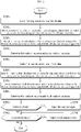
- FIG. 2 is a flowchart illustrating exemplarily a relay diagnosis method according to a first embodiment, executable by the relay diagnosis apparatus 100 shown in FIG. 1 .
- step S210 the controller 130 controls the first relay 31 and the second relay 32 into the off-state.
- step S220 the controller 130 records, in the memory, a first detection value indicating the first diagnosis voltage V 1 while the first switch SW 1 and the second switch SW 2 are being controlled into the on-state and the off-state, respectively.
- step S230 the controller 130 records, in the memory, a second detection value indicating the second diagnosis voltage V 2 while the first switch SW 1 and the second switch SW 2 are being controlled into the off-state and the on-state, respectively.
- step S240 the controller 130 determines the first insulation resistance and the second insulation resistance based on the first detection value and the second detection value.
- step S250 the controller 130 controls the first relay 31 and the second relay 32 into the on-state.
- step S260 the controller 130 records, in the memory, a third detection value indicating the first diagnosis voltage V 1 while the first switch SW 1 and the second switch SW 2 are being controlled into the on-state and the off-state, respectively.
- step S270 the controller 130 records, in the memory, a fourth detection value indicating the second diagnosis voltage V 2 while the first switch SW 1 and the second switch SW 2 are being controlled into the off-state and the on-state, respectively.
- step S280 the controller 130 determines the third insulation resistance and the fourth insulation resistance based on the third detection value and the fourth detection value.
- step S292 the controller 130 determines if the first relay 31 is faulty by comparing the first insulation resistance with the third insulation resistance. (i) When a resistance difference between the first insulation resistance and the third insulation resistance is equal to or less than the threshold resistance or (ii) when a ratio of the resistance difference to the first insulation resistance is equal to or less than a threshold ratio, the controller 130 may determine that the first relay 31 is faulty. When a value of the step S292 is "YES", step S294 may be performed.
- the controller 130 outputs a first diagnosis signal indicating that the first relay 31 is faulty.
- the first diagnosis signal may be transmitted to an external device via wired/wireless communication.
- step S296 the controller 130 determines if the second relay 32 is faulty by comparing the second insulation resistance with the fourth insulation resistance. (i) When a resistance difference between the second insulation resistance and the fourth insulation resistance is equal to or less than the threshold resistance or (ii) when a ratio of the resistance difference to the second insulation resistance is equal to or less than the threshold ratio, the controller 130 may determine that the second relay 32 is faulty. When a value of the step S296 is "YES", step S298 may be performed.
- the controller 130 outputs a second diagnosis signal indicating that the second relay 32 is faulty.
- the second diagnosis signal may be transmitted to an external device via wired/wireless communication.
- FIGS. 3 and 4 are flowcharts illustrating exemplarily a relay diagnosis method according to a second embodiment, executable by the relay diagnosis apparatus 100 shown in FIG. 1 .
- the method of FIG. 3 may be additionally performed when the first relay 31 is determined to be faulty in the step S292 of FIG. 2 .
- the controller 130 determines if the third insulation resistance is equal to or higher than first reference resistance.
- the first reference resistance may be a predetermined value indicating the combined resistance of the insulation resistance R A1 and the insulation resistance R B1 when both the first insulation condition and the third insulation condition are normal.
- the third insulation resistance that is equal to or higher than the first reference resistance represents that (i) at least the first insulation condition is normal among the first insulation condition and the third insulation condition, and (ii) the first relay 31 is in an open circuit fault.
- step S320 the controller 130 outputs a third diagnosis signal indicating that the first insulation condition is normal and the first relay 31 is in the open circuit fault.
- the third diagnosis signal may be transmitted to an external device via wired/wireless communication.
- the method of FIG. 4 may be additionally performed when the first relay 31 is determined to be faulty in the step S292 of FIG. 2 .
- the controller 130 determines if the fourth insulation resistance is equal to or higher than second reference resistance.
- the second reference resistance may be a predetermined value indicating the combined resistance of the insulation resistance R A2 and the insulation resistance R B2 when both the second insulation condition and the fourth insulation condition are normal.
- the second reference resistance may be equal to the first reference resistance.
- the fourth insulation resistance that is equal to or higher than the second reference resistance represents that (i) at least the second insulation condition is normal among the second insulation condition and the fourth insulation condition, and (ii) the second relay 32 is in an open circuit fault.
- step S420 the controller 130 outputs a fourth diagnosis signal indicating that the second insulation condition is normal and the second relay 32 is in the open circuit fault.
- the fourth diagnosis signal may be transmitted to an external device via wired/wireless communication.
Landscapes
- Engineering & Computer Science (AREA)
- Physics & Mathematics (AREA)
- General Physics & Mathematics (AREA)
- Power Engineering (AREA)
- Life Sciences & Earth Sciences (AREA)
- Sustainable Development (AREA)
- Sustainable Energy (AREA)
- Transportation (AREA)
- Mechanical Engineering (AREA)
- Testing Of Short-Circuits, Discontinuities, Leakage, Or Incorrect Line Connections (AREA)
- Electric Propulsion And Braking For Vehicles (AREA)
Applications Claiming Priority (2)
| Application Number | Priority Date | Filing Date | Title |
|---|---|---|---|
| KR1020200133688A KR102808648B1 (ko) | 2020-10-15 | 2020-10-15 | 릴레이 진단 장치, 릴레이 진단 방법, 배터리 시스템 및 전기 차량 |
| PCT/KR2021/013269 WO2022080709A1 (fr) | 2020-10-15 | 2021-09-28 | Dispositif de diagnostic de relais, procédé de diagnostic de relais, système de batterie et véhicule électrique |
Publications (3)
| Publication Number | Publication Date |
|---|---|
| EP4099034A1 true EP4099034A1 (fr) | 2022-12-07 |
| EP4099034A4 EP4099034A4 (fr) | 2023-10-11 |
| EP4099034B1 EP4099034B1 (fr) | 2026-03-25 |
Family
ID=81209103
Family Applications (1)
| Application Number | Title | Priority Date | Filing Date |
|---|---|---|---|
| EP21880357.5A Active EP4099034B1 (fr) | 2020-10-15 | 2021-09-28 | Dispositif de diagnostic de relais, procédé de diagnostic de relais, système de batterie et véhicule électrique |
Country Status (6)
| Country | Link |
|---|---|
| US (1) | US11774499B2 (fr) |
| EP (1) | EP4099034B1 (fr) |
| JP (1) | JP7416488B2 (fr) |
| KR (1) | KR102808648B1 (fr) |
| CN (1) | CN115136016B (fr) |
| WO (1) | WO2022080709A1 (fr) |
Families Citing this family (15)
| Publication number | Priority date | Publication date | Assignee | Title |
|---|---|---|---|---|
| FR3079305B1 (fr) * | 2018-03-23 | 2020-05-01 | IFP Energies Nouvelles | Procede de determination d'au moins deux resistances equivalentes d'isolement d'un systeme electrique |
| JP7585722B2 (ja) * | 2020-11-09 | 2024-11-19 | オムロン株式会社 | 絶縁抵抗監視装置 |
| JP7392755B2 (ja) * | 2022-03-24 | 2023-12-06 | いすゞ自動車株式会社 | 固着診断装置および固着診断方法 |
| KR20240006194A (ko) | 2022-07-06 | 2024-01-15 | 씨앤지하이테크 주식회사 | 제너다이오드를 이용하여 전원공급에 대해 고장을 검출하는 장치 |
| KR102946740B1 (ko) * | 2022-09-16 | 2026-03-31 | 주식회사 엘지에너지솔루션 | 릴레이 진단 장치 및 이를 포함하는 배터리 팩 |
| KR20240168003A (ko) * | 2023-05-22 | 2024-11-29 | 주식회사 엘지에너지솔루션 | 릴레이 진단 회로 및 이를 포함하는 배터리 장치 |
| CN118534183A (zh) * | 2024-05-14 | 2024-08-23 | 深蓝汽车科技有限公司 | 一种继电器外侧总电压确定方法、装置、车辆及存储介质 |
| KR102917502B1 (ko) * | 2024-07-10 | 2026-01-27 | 한국자동차연구원 | 스위칭 소자의 절연저항 검사 장치 및 방법 |
| KR102917503B1 (ko) * | 2024-07-10 | 2026-01-27 | 한국자동차연구원 | 인버터의 절연저항 검사 장치 및 방법 |
| KR102917504B1 (ko) * | 2024-07-11 | 2026-01-27 | 한국자동차연구원 | 컨버터의 절연저항 검사 장치 및 방법 |
| CN118837733B (zh) * | 2024-07-12 | 2025-05-20 | 合肥力高动力科技有限公司 | 一种车载bms功能安全架构中紧急路径回路的检测方法、系统、设备及介质 |
| CN119024158B (zh) * | 2024-10-29 | 2025-02-28 | 宁德时代新能源科技股份有限公司 | 继电器检测方法、装置、电池管理系统、介质及程序产品 |
| CN119024159B (zh) * | 2024-10-31 | 2025-03-04 | 宁德时代新能源科技股份有限公司 | 继电器粘连诊断方法、装置以及系统 |
| CN120382857A (zh) * | 2025-03-31 | 2025-07-29 | 浙江万安科技股份有限公司 | 一种汽车智能底盘电控系统及其控制电路 |
| CN121454307A (zh) * | 2026-01-08 | 2026-02-03 | 宁德时代润智软件科技有限公司 | 继电器粘连检测方法、装置、电池管理系统和电池设备 |
Family Cites Families (22)
| Publication number | Priority date | Publication date | Assignee | Title |
|---|---|---|---|---|
| JP4265381B2 (ja) * | 2003-11-13 | 2009-05-20 | 日産自動車株式会社 | リレーの故障判定装置およびリレーの故障判定方法 |
| JP2007329045A (ja) * | 2006-06-08 | 2007-12-20 | Nissan Motor Co Ltd | リレー故障診断装置 |
| KR101750073B1 (ko) | 2011-10-13 | 2017-07-03 | 에스케이이노베이션 주식회사 | 릴레이 융착 모니터링 회로 |
| KR20130119666A (ko) | 2012-04-24 | 2013-11-01 | 에스케이이노베이션 주식회사 | 릴레이 융착 위치 판단 회로 |
| JP6146332B2 (ja) | 2013-09-11 | 2017-06-14 | トヨタ自動車株式会社 | リレーの固着判別システム |
| KR101771226B1 (ko) * | 2014-10-02 | 2017-09-05 | 주식회사 엘지화학 | 신속하게 절연 저항을 측정할 수 있는 절연 저항 측정 장치 및 방법 |
| KR101637768B1 (ko) * | 2014-12-08 | 2016-07-07 | 현대자동차주식회사 | 차량 배터리 관리 시스템의 절연파괴 고장 부품 진단 및 안내 방법 |
| JP6589368B2 (ja) | 2015-05-20 | 2019-10-16 | 日産自動車株式会社 | 電源装置、及び、電源装置の異常を診断する診断方法 |
| US10126344B2 (en) * | 2015-12-18 | 2018-11-13 | Faraday&Future Inc. | Method for measuring electrical isolation of a vehicle chassis |
| JP6713291B2 (ja) | 2016-02-05 | 2020-06-24 | 株式会社デンソーテン | 溶着検知装置及び溶着検知方法 |
| JP6391608B2 (ja) | 2016-02-10 | 2018-09-19 | 株式会社デンソーテン | 異常検知装置及び異常検知方法 |
| JP6753715B2 (ja) * | 2016-07-20 | 2020-09-09 | 株式会社東芝 | 漏電検出装置および漏電検出方法 |
| JP6742191B2 (ja) | 2016-08-08 | 2020-08-19 | 株式会社デンソーテン | 固着検出装置および電池システム |
| KR101795319B1 (ko) | 2016-12-13 | 2017-12-01 | 현대자동차주식회사 | 차량의 고전압 시스템의 퓨즈 단선 검출 시스템 및 방법 |
| JP2018196285A (ja) * | 2017-05-19 | 2018-12-06 | パナソニックIpマネジメント株式会社 | 電源制御装置、溶着検出方法およびリレー溶着検出装置 |
| KR102291762B1 (ko) | 2017-11-07 | 2021-09-03 | 주식회사 엘지에너지솔루션 | 릴레이 진단 회로 |
| KR102270232B1 (ko) * | 2017-12-11 | 2021-06-25 | 주식회사 엘지에너지솔루션 | 배터리 팩의 양극 컨택터 진단 장치 및 방법 |
| KR102270233B1 (ko) | 2017-12-12 | 2021-06-25 | 주식회사 엘지에너지솔루션 | 배터리 팩의 음극 컨택터 진단 장치 및 방법 |
| KR102432892B1 (ko) | 2018-03-14 | 2022-08-12 | 주식회사 엘지에너지솔루션 | 릴레이의 고장을 진단하기 위한 장치 및 방법 |
| KR102155207B1 (ko) | 2019-07-05 | 2020-09-11 | 주식회사 라온텍 | 절연저항 측정 장치, 이를 구비한 배터리 관리 시스템 및 절연저항 측정 방법 |
| US11592485B2 (en) * | 2019-10-04 | 2023-02-28 | Farasis Energy (Ganzhou) Co., Ltd. | Methods and apparatus for contactor weld detection in a vehicle |
| KR20200133688A (ko) | 2020-11-10 | 2020-11-30 | (주) 대동이엔지 | 다단 실린더형 스토퍼유닛를 가진 브리오 진동리퍼 |
-
2020
- 2020-10-15 KR KR1020200133688A patent/KR102808648B1/ko active Active
-
2021
- 2021-09-28 US US17/798,151 patent/US11774499B2/en active Active
- 2021-09-28 CN CN202180015610.7A patent/CN115136016B/zh active Active
- 2021-09-28 EP EP21880357.5A patent/EP4099034B1/fr active Active
- 2021-09-28 JP JP2022544363A patent/JP7416488B2/ja active Active
- 2021-09-28 WO PCT/KR2021/013269 patent/WO2022080709A1/fr not_active Ceased
Also Published As
| Publication number | Publication date |
|---|---|
| US20230099667A1 (en) | 2023-03-30 |
| US11774499B2 (en) | 2023-10-03 |
| CN115136016B (zh) | 2025-12-09 |
| KR20220049950A (ko) | 2022-04-22 |
| KR102808648B1 (ko) | 2025-05-14 |
| WO2022080709A1 (fr) | 2022-04-21 |
| JP7416488B2 (ja) | 2024-01-17 |
| JP2023511169A (ja) | 2023-03-16 |
| EP4099034B1 (fr) | 2026-03-25 |
| EP4099034A4 (fr) | 2023-10-11 |
| CN115136016A (zh) | 2022-09-30 |
Similar Documents
| Publication | Publication Date | Title |
|---|---|---|
| EP4099034B1 (fr) | Dispositif de diagnostic de relais, procédé de diagnostic de relais, système de batterie et véhicule électrique | |
| US12203987B2 (en) | Relay diagnosis apparatus, relay diagnosis method, battery system and electric vehicle | |
| US12203996B2 (en) | Battery management system, battery pack, electric vehicle and battery management method | |
| US20240044999A1 (en) | Battery Management System, Battery Pack, Electric Vehicle, and Battery Management Method | |
| CN107850643B (zh) | 用于诊断开关元件的故障的装置和方法 | |
| US12036875B2 (en) | Electric leakage detection apparatus, electric leakage detection method and electric vehicle | |
| US12474380B2 (en) | Battery management system, battery pack, energy storage system and battery management method | |
| US12613289B2 (en) | Battery diagnosis apparatus, battery pack, electric vehicle, and battery diagnosis method | |
| EP3624250B1 (fr) | Bloc batterie | |
| EP4253972A1 (fr) | Dispositif de diagnostic de batterie, système de gestion de batterie, bloc-batterie, véhicule électrique et procédé de diagnostic de batterie | |
| US12322766B2 (en) | Battery management system, battery pack, electric vehicle and battery management method | |
| KR20220001364A (ko) | 배터리 관리 장치, 배터리 팩, 에너지 저장 시스템 및 배터리 관리 방법 | |
| EP4549968B1 (fr) | Appareil de diagnostic de batterie, procédé de diagnostic de batterie, bloc-batterie et véhicule | |
| KR102767781B1 (ko) | 누전 검출 장치, 누전 검출 방법 및 전기 차량 | |
| KR102839450B1 (ko) | 배터리 장치 및 드리프트 오류 진단 방법 |
Legal Events
| Date | Code | Title | Description |
|---|---|---|---|
| STAA | Information on the status of an ep patent application or granted ep patent |
Free format text: STATUS: THE INTERNATIONAL PUBLICATION HAS BEEN MADE |
|
| PUAI | Public reference made under article 153(3) epc to a published international application that has entered the european phase |
Free format text: ORIGINAL CODE: 0009012 |
|
| STAA | Information on the status of an ep patent application or granted ep patent |
Free format text: STATUS: REQUEST FOR EXAMINATION WAS MADE |
|
| 17P | Request for examination filed |
Effective date: 20220902 |
|
| AK | Designated contracting states |
Kind code of ref document: A1 Designated state(s): AL AT BE BG CH CY CZ DE DK EE ES FI FR GB GR HR HU IE IS IT LI LT LU LV MC MK MT NL NO PL PT RO RS SE SI SK SM TR |
|
| A4 | Supplementary search report drawn up and despatched |
Effective date: 20230912 |
|
| RIC1 | Information provided on ipc code assigned before grant |
Ipc: G01R 31/52 20200101ALN20230906BHEP Ipc: B60L 58/18 20190101ALI20230906BHEP Ipc: B60L 3/00 20190101ALI20230906BHEP Ipc: G01R 31/327 20060101AFI20230906BHEP |
|
| DAV | Request for validation of the european patent (deleted) | ||
| DAX | Request for extension of the european patent (deleted) | ||
| GRAP | Despatch of communication of intention to grant a patent |
Free format text: ORIGINAL CODE: EPIDOSNIGR1 |
|
| STAA | Information on the status of an ep patent application or granted ep patent |
Free format text: STATUS: GRANT OF PATENT IS INTENDED |
|
| RIC1 | Information provided on ipc code assigned before grant |
Ipc: G01R 31/327 20060101AFI20251006BHEP Ipc: B60L 3/00 20190101ALI20251006BHEP Ipc: B60L 58/18 20190101ALI20251006BHEP Ipc: G01R 31/52 20200101ALN20251006BHEP |
|
| INTG | Intention to grant announced |
Effective date: 20251016 |
|
| P01 | Opt-out of the competence of the unified patent court (upc) registered |
Free format text: CASE NUMBER: UPC_APP_0012143_4099034/2025 Effective date: 20251105 |
|
| GRAS | Grant fee paid |
Free format text: ORIGINAL CODE: EPIDOSNIGR3 |
|
| GRAA | (expected) grant |
Free format text: ORIGINAL CODE: 0009210 |
|
| STAA | Information on the status of an ep patent application or granted ep patent |
Free format text: STATUS: THE PATENT HAS BEEN GRANTED |
|
| AK | Designated contracting states |
Kind code of ref document: B1 Designated state(s): AL AT BE BG CH CY CZ DE DK EE ES FI FR GB GR HR HU IE IS IT LI LT LU LV MC MK MT NL NO PL PT RO RS SE SI SK SM TR |
|
| REG | Reference to a national code |
Ref country code: CH Ref legal event code: F10 Free format text: ST27 STATUS EVENT CODE: U-0-0-F10-F00 (AS PROVIDED BY THE NATIONAL OFFICE) Effective date: 20260325 Ref country code: GB Ref legal event code: FG4D |
|
| REG | Reference to a national code |
Ref country code: DE Ref legal event code: R096 Ref document number: 602021050821 Country of ref document: DE |
|
| REG | Reference to a national code |
Ref country code: IE Ref legal event code: FG4D |