EP4099084A1 - Optischer funktionsfilm für head-up display, optisches laminat, funktionsglas und head-up display system - Google Patents
Optischer funktionsfilm für head-up display, optisches laminat, funktionsglas und head-up display system Download PDFInfo
- Publication number
- EP4099084A1 EP4099084A1 EP21746935.2A EP21746935A EP4099084A1 EP 4099084 A1 EP4099084 A1 EP 4099084A1 EP 21746935 A EP21746935 A EP 21746935A EP 4099084 A1 EP4099084 A1 EP 4099084A1
- Authority
- EP
- European Patent Office
- Prior art keywords
- slow axis
- polarized light
- glass
- optical
- display
- Prior art date
- Legal status (The legal status is an assumption and is not a legal conclusion. Google has not performed a legal analysis and makes no representation as to the accuracy of the status listed.)
- Pending
Links
Images



Classifications
-
- B—PERFORMING OPERATIONS; TRANSPORTING
- B32—LAYERED PRODUCTS
- B32B—LAYERED PRODUCTS, i.e. PRODUCTS BUILT-UP OF STRATA OF FLAT OR NON-FLAT, e.g. CELLULAR OR HONEYCOMB, FORM
- B32B17/00—Layered products essentially comprising sheet glass, or glass, slag, or like fibres
- B32B17/06—Layered products essentially comprising sheet glass, or glass, slag, or like fibres comprising glass as the main or only constituent of a layer, next to another layer of a specific material
- B32B17/10—Layered products essentially comprising sheet glass, or glass, slag, or like fibres comprising glass as the main or only constituent of a layer, next to another layer of a specific material of synthetic resin
- B32B17/10005—Layered products essentially comprising sheet glass, or glass, slag, or like fibres comprising glass as the main or only constituent of a layer, next to another layer of a specific material of synthetic resin laminated safety glass or glazing
- B32B17/10009—Layered products essentially comprising sheet glass, or glass, slag, or like fibres comprising glass as the main or only constituent of a layer, next to another layer of a specific material of synthetic resin laminated safety glass or glazing characterized by the number, the constitution or treatment of glass sheets
- B32B17/10036—Layered products essentially comprising sheet glass, or glass, slag, or like fibres comprising glass as the main or only constituent of a layer, next to another layer of a specific material of synthetic resin laminated safety glass or glazing characterized by the number, the constitution or treatment of glass sheets comprising two outer glass sheets
-
- G—PHYSICS
- G02—OPTICS
- G02B—OPTICAL ELEMENTS, SYSTEMS OR APPARATUS
- G02B27/00—Optical systems or apparatus not provided for by any of the groups G02B1/00 - G02B26/00, G02B30/00
- G02B27/01—Head-up displays
- G02B27/0101—Head-up displays characterised by optical features
-
- B—PERFORMING OPERATIONS; TRANSPORTING
- B32—LAYERED PRODUCTS
- B32B—LAYERED PRODUCTS, i.e. PRODUCTS BUILT-UP OF STRATA OF FLAT OR NON-FLAT, e.g. CELLULAR OR HONEYCOMB, FORM
- B32B17/00—Layered products essentially comprising sheet glass, or glass, slag, or like fibres
- B32B17/06—Layered products essentially comprising sheet glass, or glass, slag, or like fibres comprising glass as the main or only constituent of a layer, next to another layer of a specific material
- B32B17/10—Layered products essentially comprising sheet glass, or glass, slag, or like fibres comprising glass as the main or only constituent of a layer, next to another layer of a specific material of synthetic resin
- B32B17/10005—Layered products essentially comprising sheet glass, or glass, slag, or like fibres comprising glass as the main or only constituent of a layer, next to another layer of a specific material of synthetic resin laminated safety glass or glazing
- B32B17/10165—Functional features of the laminated safety glass or glazing
- B32B17/10431—Specific parts for the modulation of light incorporated into the laminated safety glass or glazing
- B32B17/1044—Invariable transmission
- B32B17/10458—Polarization selective transmission
-
- B—PERFORMING OPERATIONS; TRANSPORTING
- B32—LAYERED PRODUCTS
- B32B—LAYERED PRODUCTS, i.e. PRODUCTS BUILT-UP OF STRATA OF FLAT OR NON-FLAT, e.g. CELLULAR OR HONEYCOMB, FORM
- B32B17/00—Layered products essentially comprising sheet glass, or glass, slag, or like fibres
- B32B17/06—Layered products essentially comprising sheet glass, or glass, slag, or like fibres comprising glass as the main or only constituent of a layer, next to another layer of a specific material
- B32B17/10—Layered products essentially comprising sheet glass, or glass, slag, or like fibres comprising glass as the main or only constituent of a layer, next to another layer of a specific material of synthetic resin
- B32B17/10005—Layered products essentially comprising sheet glass, or glass, slag, or like fibres comprising glass as the main or only constituent of a layer, next to another layer of a specific material of synthetic resin laminated safety glass or glazing
- B32B17/1055—Layered products essentially comprising sheet glass, or glass, slag, or like fibres comprising glass as the main or only constituent of a layer, next to another layer of a specific material of synthetic resin laminated safety glass or glazing characterized by the resin layer, i.e. interlayer
- B32B17/10605—Type of plasticiser
-
- B—PERFORMING OPERATIONS; TRANSPORTING
- B32—LAYERED PRODUCTS
- B32B—LAYERED PRODUCTS, i.e. PRODUCTS BUILT-UP OF STRATA OF FLAT OR NON-FLAT, e.g. CELLULAR OR HONEYCOMB, FORM
- B32B17/00—Layered products essentially comprising sheet glass, or glass, slag, or like fibres
- B32B17/06—Layered products essentially comprising sheet glass, or glass, slag, or like fibres comprising glass as the main or only constituent of a layer, next to another layer of a specific material
- B32B17/10—Layered products essentially comprising sheet glass, or glass, slag, or like fibres comprising glass as the main or only constituent of a layer, next to another layer of a specific material of synthetic resin
- B32B17/10005—Layered products essentially comprising sheet glass, or glass, slag, or like fibres comprising glass as the main or only constituent of a layer, next to another layer of a specific material of synthetic resin laminated safety glass or glazing
- B32B17/1055—Layered products essentially comprising sheet glass, or glass, slag, or like fibres comprising glass as the main or only constituent of a layer, next to another layer of a specific material of synthetic resin laminated safety glass or glazing characterized by the resin layer, i.e. interlayer
- B32B17/10761—Layered products essentially comprising sheet glass, or glass, slag, or like fibres comprising glass as the main or only constituent of a layer, next to another layer of a specific material of synthetic resin laminated safety glass or glazing characterized by the resin layer, i.e. interlayer containing vinyl acetal
-
- B—PERFORMING OPERATIONS; TRANSPORTING
- B32—LAYERED PRODUCTS
- B32B—LAYERED PRODUCTS, i.e. PRODUCTS BUILT-UP OF STRATA OF FLAT OR NON-FLAT, e.g. CELLULAR OR HONEYCOMB, FORM
- B32B17/00—Layered products essentially comprising sheet glass, or glass, slag, or like fibres
- B32B17/06—Layered products essentially comprising sheet glass, or glass, slag, or like fibres comprising glass as the main or only constituent of a layer, next to another layer of a specific material
- B32B17/10—Layered products essentially comprising sheet glass, or glass, slag, or like fibres comprising glass as the main or only constituent of a layer, next to another layer of a specific material of synthetic resin
- B32B17/10005—Layered products essentially comprising sheet glass, or glass, slag, or like fibres comprising glass as the main or only constituent of a layer, next to another layer of a specific material of synthetic resin laminated safety glass or glazing
- B32B17/10807—Making laminated safety glass or glazing; Apparatus therefor
- B32B17/10899—Making laminated safety glass or glazing; Apparatus therefor by introducing interlayers of synthetic resin
- B32B17/10935—Making laminated safety glass or glazing; Apparatus therefor by introducing interlayers of synthetic resin as a preformed layer, e.g. formed by extrusion
-
- B—PERFORMING OPERATIONS; TRANSPORTING
- B32—LAYERED PRODUCTS
- B32B—LAYERED PRODUCTS, i.e. PRODUCTS BUILT-UP OF STRATA OF FLAT OR NON-FLAT, e.g. CELLULAR OR HONEYCOMB, FORM
- B32B27/00—Layered products comprising a layer of synthetic resin
- B32B27/06—Layered products comprising a layer of synthetic resin as the main or only constituent of a layer, which is next to another layer of the same or of a different material
- B32B27/08—Layered products comprising a layer of synthetic resin as the main or only constituent of a layer, which is next to another layer of the same or of a different material of synthetic resin
-
- B—PERFORMING OPERATIONS; TRANSPORTING
- B32—LAYERED PRODUCTS
- B32B—LAYERED PRODUCTS, i.e. PRODUCTS BUILT-UP OF STRATA OF FLAT OR NON-FLAT, e.g. CELLULAR OR HONEYCOMB, FORM
- B32B27/00—Layered products comprising a layer of synthetic resin
- B32B27/18—Layered products comprising a layer of synthetic resin characterised by the use of special additives
- B32B27/22—Layered products comprising a layer of synthetic resin characterised by the use of special additives using plasticisers
-
- B—PERFORMING OPERATIONS; TRANSPORTING
- B32—LAYERED PRODUCTS
- B32B—LAYERED PRODUCTS, i.e. PRODUCTS BUILT-UP OF STRATA OF FLAT OR NON-FLAT, e.g. CELLULAR OR HONEYCOMB, FORM
- B32B27/00—Layered products comprising a layer of synthetic resin
- B32B27/30—Layered products comprising a layer of synthetic resin comprising vinyl (co)polymers; comprising acrylic (co)polymers
-
- B—PERFORMING OPERATIONS; TRANSPORTING
- B32—LAYERED PRODUCTS
- B32B—LAYERED PRODUCTS, i.e. PRODUCTS BUILT-UP OF STRATA OF FLAT OR NON-FLAT, e.g. CELLULAR OR HONEYCOMB, FORM
- B32B27/00—Layered products comprising a layer of synthetic resin
- B32B27/36—Layered products comprising a layer of synthetic resin comprising polyesters
-
- B—PERFORMING OPERATIONS; TRANSPORTING
- B32—LAYERED PRODUCTS
- B32B—LAYERED PRODUCTS, i.e. PRODUCTS BUILT-UP OF STRATA OF FLAT OR NON-FLAT, e.g. CELLULAR OR HONEYCOMB, FORM
- B32B5/00—Layered products characterised by the non- homogeneity or physical structure, i.e. comprising a fibrous, filamentary, particulate or foam layer; Layered products characterised by having a layer differing constitutionally or physically in different parts
- B32B5/14—Layered products characterised by the non- homogeneity or physical structure, i.e. comprising a fibrous, filamentary, particulate or foam layer; Layered products characterised by having a layer differing constitutionally or physically in different parts characterised by a layer differing constitutionally or physically in different parts, e.g. denser near its faces
-
- B—PERFORMING OPERATIONS; TRANSPORTING
- B32—LAYERED PRODUCTS
- B32B—LAYERED PRODUCTS, i.e. PRODUCTS BUILT-UP OF STRATA OF FLAT OR NON-FLAT, e.g. CELLULAR OR HONEYCOMB, FORM
- B32B5/00—Layered products characterised by the non- homogeneity or physical structure, i.e. comprising a fibrous, filamentary, particulate or foam layer; Layered products characterised by having a layer differing constitutionally or physically in different parts
- B32B5/14—Layered products characterised by the non- homogeneity or physical structure, i.e. comprising a fibrous, filamentary, particulate or foam layer; Layered products characterised by having a layer differing constitutionally or physically in different parts characterised by a layer differing constitutionally or physically in different parts, e.g. denser near its faces
- B32B5/142—Variation across the area of the layer
-
- B—PERFORMING OPERATIONS; TRANSPORTING
- B32—LAYERED PRODUCTS
- B32B—LAYERED PRODUCTS, i.e. PRODUCTS BUILT-UP OF STRATA OF FLAT OR NON-FLAT, e.g. CELLULAR OR HONEYCOMB, FORM
- B32B7/00—Layered products characterised by the relation between layers; Layered products characterised by the relative orientation of features between layers, or by the relative values of a measurable parameter between layers, i.e. products comprising layers having different physical, chemical or physicochemical properties; Layered products characterised by the interconnection of layers
- B32B7/04—Interconnection of layers
- B32B7/12—Interconnection of layers using interposed adhesives or interposed materials with bonding properties
-
- B—PERFORMING OPERATIONS; TRANSPORTING
- B60—VEHICLES IN GENERAL
- B60K—ARRANGEMENT OR MOUNTING OF PROPULSION UNITS OR OF TRANSMISSIONS IN VEHICLES; ARRANGEMENT OR MOUNTING OF PLURAL DIVERSE PRIME-MOVERS IN VEHICLES; AUXILIARY DRIVES FOR VEHICLES; INSTRUMENTATION OR DASHBOARDS FOR VEHICLES; ARRANGEMENTS IN CONNECTION WITH COOLING, AIR INTAKE, GAS EXHAUST OR FUEL SUPPLY OF PROPULSION UNITS IN VEHICLES
- B60K35/00—Instruments specially adapted for vehicles; Arrangement of instruments in or on vehicles
- B60K35/20—Output arrangements, i.e. from vehicle to user, associated with vehicle functions or specially adapted therefor
- B60K35/21—Output arrangements, i.e. from vehicle to user, associated with vehicle functions or specially adapted therefor using visual output, e.g. blinking lights or matrix displays
- B60K35/23—Head-up displays [HUD]
- B60K35/231—Head-up displays [HUD] characterised by their arrangement or structure for integration into vehicles
-
- G—PHYSICS
- G02—OPTICS
- G02B—OPTICAL ELEMENTS, SYSTEMS OR APPARATUS
- G02B5/00—Optical elements other than lenses
- G02B5/18—Diffraction gratings
- G02B5/1833—Diffraction gratings comprising birefringent materials
-
- G—PHYSICS
- G02—OPTICS
- G02B—OPTICAL ELEMENTS, SYSTEMS OR APPARATUS
- G02B5/00—Optical elements other than lenses
- G02B5/30—Polarising elements
- G02B5/3016—Polarising elements involving passive liquid crystal elements
-
- B—PERFORMING OPERATIONS; TRANSPORTING
- B32—LAYERED PRODUCTS
- B32B—LAYERED PRODUCTS, i.e. PRODUCTS BUILT-UP OF STRATA OF FLAT OR NON-FLAT, e.g. CELLULAR OR HONEYCOMB, FORM
- B32B2255/00—Coating on the layer surface
- B32B2255/10—Coating on the layer surface on synthetic resin layer or on natural or synthetic rubber layer
-
- B—PERFORMING OPERATIONS; TRANSPORTING
- B32—LAYERED PRODUCTS
- B32B—LAYERED PRODUCTS, i.e. PRODUCTS BUILT-UP OF STRATA OF FLAT OR NON-FLAT, e.g. CELLULAR OR HONEYCOMB, FORM
- B32B2255/00—Coating on the layer surface
- B32B2255/26—Polymeric coating
-
- B—PERFORMING OPERATIONS; TRANSPORTING
- B32—LAYERED PRODUCTS
- B32B—LAYERED PRODUCTS, i.e. PRODUCTS BUILT-UP OF STRATA OF FLAT OR NON-FLAT, e.g. CELLULAR OR HONEYCOMB, FORM
- B32B2255/00—Coating on the layer surface
- B32B2255/28—Multiple coating on one surface
-
- B—PERFORMING OPERATIONS; TRANSPORTING
- B32—LAYERED PRODUCTS
- B32B—LAYERED PRODUCTS, i.e. PRODUCTS BUILT-UP OF STRATA OF FLAT OR NON-FLAT, e.g. CELLULAR OR HONEYCOMB, FORM
- B32B2307/00—Properties of the layers or laminate
- B32B2307/40—Properties of the layers or laminate having particular optical properties
- B32B2307/412—Transparent
-
- B—PERFORMING OPERATIONS; TRANSPORTING
- B32—LAYERED PRODUCTS
- B32B—LAYERED PRODUCTS, i.e. PRODUCTS BUILT-UP OF STRATA OF FLAT OR NON-FLAT, e.g. CELLULAR OR HONEYCOMB, FORM
- B32B2307/00—Properties of the layers or laminate
- B32B2307/40—Properties of the layers or laminate having particular optical properties
- B32B2307/416—Reflective
-
- B—PERFORMING OPERATIONS; TRANSPORTING
- B32—LAYERED PRODUCTS
- B32B—LAYERED PRODUCTS, i.e. PRODUCTS BUILT-UP OF STRATA OF FLAT OR NON-FLAT, e.g. CELLULAR OR HONEYCOMB, FORM
- B32B2307/00—Properties of the layers or laminate
- B32B2307/40—Properties of the layers or laminate having particular optical properties
- B32B2307/42—Polarizing, birefringent, filtering
-
- B—PERFORMING OPERATIONS; TRANSPORTING
- B32—LAYERED PRODUCTS
- B32B—LAYERED PRODUCTS, i.e. PRODUCTS BUILT-UP OF STRATA OF FLAT OR NON-FLAT, e.g. CELLULAR OR HONEYCOMB, FORM
- B32B2307/00—Properties of the layers or laminate
- B32B2307/50—Properties of the layers or laminate having particular mechanical properties
- B32B2307/514—Oriented
- B32B2307/516—Oriented mono-axially
-
- B—PERFORMING OPERATIONS; TRANSPORTING
- B32—LAYERED PRODUCTS
- B32B—LAYERED PRODUCTS, i.e. PRODUCTS BUILT-UP OF STRATA OF FLAT OR NON-FLAT, e.g. CELLULAR OR HONEYCOMB, FORM
- B32B2457/00—Electrical equipment
- B32B2457/20—Displays, e.g. liquid crystal displays, plasma displays
-
- B—PERFORMING OPERATIONS; TRANSPORTING
- B32—LAYERED PRODUCTS
- B32B—LAYERED PRODUCTS, i.e. PRODUCTS BUILT-UP OF STRATA OF FLAT OR NON-FLAT, e.g. CELLULAR OR HONEYCOMB, FORM
- B32B2605/00—Vehicles
- B32B2605/08—Cars
-
- B—PERFORMING OPERATIONS; TRANSPORTING
- B60—VEHICLES IN GENERAL
- B60K—ARRANGEMENT OR MOUNTING OF PROPULSION UNITS OR OF TRANSMISSIONS IN VEHICLES; ARRANGEMENT OR MOUNTING OF PLURAL DIVERSE PRIME-MOVERS IN VEHICLES; AUXILIARY DRIVES FOR VEHICLES; INSTRUMENTATION OR DASHBOARDS FOR VEHICLES; ARRANGEMENTS IN CONNECTION WITH COOLING, AIR INTAKE, GAS EXHAUST OR FUEL SUPPLY OF PROPULSION UNITS IN VEHICLES
- B60K2360/00—Indexing scheme associated with groups B60K35/00 or B60K37/00 relating to details of instruments or dashboards
- B60K2360/60—Structural details of dashboards or instruments
- B60K2360/66—Projection screens or combiners
-
- B—PERFORMING OPERATIONS; TRANSPORTING
- B60—VEHICLES IN GENERAL
- B60K—ARRANGEMENT OR MOUNTING OF PROPULSION UNITS OR OF TRANSMISSIONS IN VEHICLES; ARRANGEMENT OR MOUNTING OF PLURAL DIVERSE PRIME-MOVERS IN VEHICLES; AUXILIARY DRIVES FOR VEHICLES; INSTRUMENTATION OR DASHBOARDS FOR VEHICLES; ARRANGEMENTS IN CONNECTION WITH COOLING, AIR INTAKE, GAS EXHAUST OR FUEL SUPPLY OF PROPULSION UNITS IN VEHICLES
- B60K37/00—Dashboards
- B60K37/20—Dashboard panels
-
- G—PHYSICS
- G02—OPTICS
- G02B—OPTICAL ELEMENTS, SYSTEMS OR APPARATUS
- G02B27/00—Optical systems or apparatus not provided for by any of the groups G02B1/00 - G02B26/00, G02B30/00
- G02B27/01—Head-up displays
- G02B27/0101—Head-up displays characterised by optical features
- G02B2027/0118—Head-up displays characterised by optical features comprising devices for improving the contrast of the display / brillance control visibility
- G02B2027/012—Head-up displays characterised by optical features comprising devices for improving the contrast of the display / brillance control visibility comprising devices for attenuating parasitic image effects
-
- G—PHYSICS
- G02—OPTICS
- G02B—OPTICAL ELEMENTS, SYSTEMS OR APPARATUS
- G02B27/00—Optical systems or apparatus not provided for by any of the groups G02B1/00 - G02B26/00, G02B30/00
- G02B27/01—Head-up displays
- G02B2027/0192—Supplementary details
- G02B2027/0194—Supplementary details with combiner of laminated type, for optical or mechanical aspects
Definitions
- the present invention relates to, for example, an optical functional film, an optical laminate, and functional glass which are suitable to be applied to a head-up display, and relates to a head-up display using the same.
- a navigation system a head-up display (hereinafter also referred to as a "HUD"), and the like are used as methods for displaying information to drivers of cars and airplanes.
- a HUD is a system which projects images projected from image projection means such as a liquid crystal display (hereinafter also referred to as an "LCD”), for example, on a windshield of a car or the like.
- LCD liquid crystal display
- Emission light emitted from image display units is reflected on a reflecting mirror and further reflected on a windshield, and then reaches an observer. Although the observer sees the image projected on the windshield, it appears as if the image were at an image position beyond the windshield.
- a HUD is safer than conventional car navigation systems, in which drivers had to move their sight lines.
- a problem was that, although, in a HUD system, display information was projected while being superimposed on a scene actually seen through a windshield, the display light was reflected on the two surfaces inside and outside the windshield, resulting in the reflected image being a double image, and causing the display information to be difficult to see.
- Patent Literature 1 it is disclosed that when display light converted into S polarized light comes into a windshield for cars including a film-like optical rotator therein at a Brewster angle, some of the S polarized light is reflected on the inner surface of the windshield of a car, S polarized light transmitted through the surface is converted into P polarized light by an optical rotator, and all of the P polarized light is further emitted from the outer surface of the windshield of the car to outside of the car to prevent a double image. If the conversion between S polarized light and P polarized light is not performed very efficiently in such a windshield for cars, or the like, a double image is however formed by S polarized light which returns without being emitted outside a car.
- Patent Literature 2 a technique for letting P polarized come in using a light control film in which a circularly polarized light reflecting film manufactured using a cholesteric liquid crystal layer is clamped with two 1/4 wavelength plates.
- Patent Literature 2 converting linear polarized light which comes in into circularly polarized light by a 1/4 wavelength plate and reflecting the converted circularly polarized light on the light reflecting film manufactured using the cholesteric liquid crystal layer enable an observer to visually confirm the reflected light.
- An object of the present invention is to provide an optical functional film, an optical laminate, and functional glass for a head-up display which are excellent in polarized light conversion efficiency, and a head-up display system using the same.
- the present inventor has examined earnestly to achieve the above-mentioned object, consequently found that the polarized light conversion efficiency is improved using an optical functional film for a head-up display having a plurality of slow axes which are different in slow axis angles in the same plane in a certain range, and when the optical functional film is applied to a head-up display, the formation of a double image can be suppressed in a wide range, and completed the present invention.
- the present invention relates to following 1) to 8).
- an optical functional film, an optical laminate, and functional glass which are excellent in polarized light conversion efficiency and suitable to be applied to a head-up display, and a head-up display system using the same can be achieved.
- a head-up display may be omitted, and an optical functional film for a head-up display, an optical laminate for a head-up display, and functional glass for a head-up display may be described merely as an optical functional film, an optical laminate, and functional glass, respectively.
- Terms such as "(meth)acryloyl” and “(meth)acrylate” mean “acryloyl” or “methacryloyl” and “acrylate” or “methacrylate”, respectively.
- a "head-up display” may be expressed as an HUD.
- An optical functional film of the present invention includes at least one optical function layer having the function of converting the polarization axis of incident light to obtain desired polarized light.
- an optical function layer include a phase difference film such as a 1/2 wavelength plate or a 1/4 wavelength plate, a laminate of a plurality of phase difference films, or a laminate of those and a circularly polarized light reflecting layer.
- a phase difference film such as a 1/2 wavelength plate or a 1/4 wavelength plate, a laminate of a plurality of phase difference films, or a laminate of those and a circularly polarized light reflecting layer.
- (A-1) one or more 1/2 wavelength plates or (A-4) a laminate in which one or more circularly polarized light reflecting layers are clamped with two 1/4 wavelength plates are preferable as an optical functional film.
- the circularly polarized light reflecting layer for example, a cholesteric liquid crystal layer using a cholesteric liquid crystal is preferable.
- the optical functional film of the present invention is an optical functional film for a head-up display, having two or more slow axis zones different in slow axis angles in the same plane, wherein a maximum difference between slow axis angles is more than 5° and less than 30°.
- a slow axis is an optic axis which shows a direction of an axis wherein the refractive index reaches the maximum with respect to polarized light which comes into the surface perpendicular to the traveling direction of the light.
- a slow axis angle means its angle, namely an angle which a slow axis forms with the axis in the length direction of an optical functional film (vertical axis).
- the optical functional film of the present invention has two or more slow axis zones different in slow axis angles.
- the maximum difference between slow axis angles means the difference between the maximum slow axis angle and the minimum slow axis angle in the same plane of one optical functional film, namely a value of the greatest difference between slow axis angles among slow axis angles in the same plane.
- the optical functional film of the present invention is a film used for a head-up display. If a portion having a slow axis angle difference of 30° or more is present in a region other than a portion used as a display portion, the slow axis angle in the region is not therefore considered as the maximum slow axis angle difference.
- Fig. 1 is an illustration of an embodiment of an optical functional film having two slow axis zones in the same plane.
- one is defined as a slow axis zone A and the other is defined as a slow axis zone B among two regions which an optical functional film 30 has
- the slow axis angle of a slow axis 32 in the slow axis zone A and the slow axis angle of a slow axis 34 in the slow axis zone B exhibit angles different from each other.
- the difference between the slow axis angle 31 in the slow axis zone A and the slow axis angle 33 in the slow axis zone B is more than 5° and less than 30°, and namely the maximum difference between the slow axis angles is more than 5° and less than 30°.
- the lower limit of the maximum difference in slow axis angles is preferably 6°, and more preferably 7°, further preferably 8°, particularly preferably 10°, and the most preferably 15° or 16°.
- the upper limit of the maximum difference between slow axis angles is preferably 28°, more preferably 27°, further preferably 26°, particularly preferably 25°, and the most preferably 22°. Therefore, the most preferable maximum difference between slow axis angles is 16° or more and 22° or less.
- Fig. 2 is an illustration of an embodiment of an optical functional film having three slow axis zones in the same plane.
- the left region is defined as a slow axis zone C
- the central region is defined as a slow axis zone D
- the right region is defined as a slow axis zone E among three regions which an optical functional film 30 has, at least two of the slow axis angle of a slow axis 42 in the slow axis zone C, the slow axis angle of a slow axis 44 in the slow axis zone D, and the slow axis angle of a slow axis 46 in the slow axis zone E exhibit different angles.
- the difference between the slow axis angle 41 in the slow axis zone C and the slow axis angle 45 in the slow axis zone E is more than 5° and less than 30°, namely the maximum difference between the slow axis angles is more than 5° and less than 30°.
- the lower limit of the maximum difference between the slow axis angles is preferably 6°, more preferably 7°, further preferably 8°, particularly preferably 10°, and the most preferably 15° or 16°.
- the upper limit of the maximum difference between the slow axis angles is preferably 28°, more preferably 27°, further preferably 26°, particularly preferably 25°, and the most preferably 22°. Therefore, the most preferable maximum difference between the slow axis angles is 16° or more and 22° or less.
- the optical functional film of the present invention may be a film having three or more slow axis zones different in slow axis angles in the same plane, and the difference in slow axis angles between adjoining slow axis zones may be 5° or more and 20° or less.
- the slow axis angle 43 has a difference of 5° or more and 20° or less from the slow axis angle 41 in the slow axis zone D adjoining the slow axis zone C, namely the slow axis zone D and the slow axis zone C have a gap between the slow axis angles.
- the slow axis angle 45 has a difference of 5° or more and 20° or less from the slow axis angle 43 in the slow axis zone E adjoining the slow axis zone D, namely the slow axis zone E and the slow axis zone D has a gap between the slow axis angles.
- the lower limit of the gap in the slow axis angles between these adjoining slow axis zones is preferably 6°, further preferably 7°, and particularly preferably 8°.
- the upper limit of the gap in the slow axis angles between the adjoining slow axis zones is preferably 19°, further preferably 18°, and particularly preferably 17°. That is, it is the most preferable that the gap in the slow axis angles between the adjoining slow axis zones be 8° or more and 17° or less.
- the optical functional film of the present invention have three or more slow axis zones having different slow axis angles respectively in the same plane, and it is further preferable that the optical functional film have slow axis zones all having different slow axis angles.
- the slow axis zone C, the slow axis zone D, and the slow axis zone E in Fig. 2 have slow axis angles different from each other, and the slow axis angle 41, the slow axis angle 43, and the slow axis angle 45 are all different.
- the slow axes are all different, and, for example, a configuration such that the slow axis in the slow axis zone C is 25°, the slow axis in the slow axis zone D is 30°, and the slow axis in the slow axis zone E is 35° is meant thereby.
- the optical function layer is one 1/2 wavelength plate, it is preferable that the maximum difference between the slow axis angles be 7° or more and 13° or less, and it is more preferable that the maximum difference be 9° or more and 11° or less.
- the optical function layer is a plurality of, especially two, 1/2 wavelength plates, it is preferable that the maximum difference between the slow axis angles be 10° or more and 25° or less, and it is more preferable that the maximum difference be 18° or more and 22° or less.
- the optical function layer is a laminate in which one or more circularly polarized light reflecting layers are clamped with two 1/4 wavelength plates, it is preferable that the maximum difference between the slow axis angles be 10° or more and 25° or less, and it is more preferable that the maximum difference be 18° or more and 22° or less.
- the 1/2 wavelength plate is a phase difference element having the function of converting P polarized light into S polarized light, or converting S polarized light into P polarized light, namely converting a polarization axis, and for example, can be obtained by monoaxially stretching a film including a polycarbonate or cycloolefin polymer so that phase difference is 1/2 of a wavelength or by orienting a horizontally oriented polymerizable liquid crystal at a thickness such that the phase difference is 1/2 of a wavelength.
- the 1/2 wavelength plate using a horizontally oriented polymerizable liquid crystal generally includes a polymerizable liquid crystal layer as a layer having the action of converting a polarization axis and a supporting substrate to be coated with a coating liquid which forms the polymerizable liquid crystal layer.
- the supporting substrate is not an essential constituent member for the optical functional film of the present invention, and the polymerizable liquid crystal layer can also be transferred to other base materials (for example, an intermediate film and a glass plate) for use.
- the upper limit value of the thickness of such a 1/2 wavelength plate be 10 ⁇ m or less, and it is more preferable that the upper limit value be 5 ⁇ m or less from the viewpoint of the orientation of the liquid crystal.
- the lower limit value of the thickness of a 1/2 wavelength plate be 0.3 ⁇ m or more, and it is more preferable that the lower limit value be 0.5 ⁇ m or more from the viewpoint of the polymerizability of the liquid crystal.
- the phase difference may change depending on the incidence angle of light. In such a case, to adapt the phase difference more strictly, change in the phase difference accompanied with the incidence angle can be suppressed, for example, by using a phase difference element in which the refractive index of the phase difference element is adjusted.
- a liquid crystal composition forming the polymerizable liquid crystal layer is applied to a supporting substrate. It is preferable that such a supporting substrate be transparent in a visible light region to maintain the visibility of a display image when the 1/2 wavelength plate is used for an HUD.
- the visible light transmittance at a wavelength of 380 to 780 nm may be specifically 50% or more, it is preferable that the visible light transmittance be 70% or more, and it is more preferable that the visible light transmittance be 85% or more.
- the supporting substrate may be colored, it is preferable that the supporting substrate be not or hardly colored.
- the refractive index of the supporting substrate be 1.2 to 2.0, and it is more preferable that the refractive index be 1.4 to 1.8.
- the thickness of the supporting substrate may be suitably selected depending on the use, and is preferably 5 ⁇ m to 1000 ⁇ m, more preferably 10 ⁇ m to 250 ⁇ m, and particularly preferably 15 ⁇ m to 150 ⁇ m.
- the supporting substrate may be a monolayer, or may be a laminate having two or more layers.
- Example of the supporting substrate include triacetylcellulose (TAC), acryl, polycarbonate, polyvinyl chloride, polyolefin, and polyethylene terephthalate (PET).
- TAC triacetylcellulose
- PET polyethylene terephthalate
- the nematic liquid crystal monomer having the polymerizable group is dissolved in a solvent, and a photopolymerization initiator is subsequently added.
- a solvent such as a solvent is not particularly limited.
- the examples include cyclopentanone, toluene, methyl ethyl ketone, methyl isobutyl ketone, cyclopentanone, toluene, and the like, and cyclopentanone, toluene and the like are preferable.
- this solution is applied to a plastic substrate such as a PET film or a TAC film used as a supporting substrate so that the thickness is as uniform as possible, the solution is left to stand for a certain period of time under temperature conditions under which the solution becomes a liquid crystal, and is oriented on the supporting substrate while the solvent is removed by heating.
- the orientation of the liquid crystal can be more uniform by rubbing-treating the plastic substrate surface in a desired direction before the coating of the plastic film surface or by performing the orientation treatment of forming a photo-oriented material, which exhibits photo-orientation by polarized light irradiation, into a film on the plastic film surface, irradiating polarized light, and the like.
- the slow axes of 1/2 wavelength plates can be controlled to desired angles, and the haze values of the 1/2 wavelength plates can be reduced thereby.
- the 1/2 wavelength plate having a desired slow axis can be obtained by irradiating the nematic liquid crystal monomer with ultraviolet rays using a high-pressure mercury lamp or the like while this orientation state is maintained, and fixing the orientation of the liquid crystal.
- the main role of the 1/2 wavelength plate is to convert S polarized light or P polarized light transmitted without being reflected on the surface into P polarized light or S polarized light. Reflection from the supporting substrate disposed outside can be reduced, and a double image is suppressed thereby.
- a 1/4 wavelength plate can also be used as an optical functional layer depending on the design of a HUD system.
- the 1/4 wavelength plate is a phase difference element having the function of converting circularly polarized light into linear polarized light, and, for example, can be obtained by monoaxially stretching a film including a polycarbonate or cycloolefin polymer so that the phase difference is 1/4 of a wavelength or by orienting a horizontally oriented polymerizable liquid crystal at a thickness such that the phase difference is 1/4 of a wavelength.
- a polymerizable liquid crystal layer be included in the 1/4 wavelength plate in the same way as the 1/2 wavelength plate.
- the 1/4 wavelength plate includes a polymerizable liquid crystal layer as a layer having the action of converting a polarization axis and a supporting substrate to be coated with a coating liquid which forms the polymerizable liquid crystal layer.
- the same materials as the nematic liquid crystal monomer and the supporting substrate to be used in the above-mentioned 1/2 wavelength plate can be used for the polymerizable liquid crystal layer and the supporting substrate.
- a phase difference element called a broadband 1/4 wavelength plate may be used as the 1/4 wavelength plate.
- the broadband 1/4 wavelength plate is a phase difference element in which the wavelength dependence of the phase difference is reduced. Examples include a phase difference element in which a 1/2 wavelength plate and a 1/4 wavelength plate having the same wavelength dispersion are laminated so that an angle which the respective slow axes form is 60° and a polycarbonate-based phase difference element in which the wavelength dependence of the phase difference is reduced (manufactured by TEIJIN LIMITED: PURE-ACE WR-S).
- the phase difference may change with the incidence angle of light depending on the phase difference element.
- a change in the phase difference with the incidence angle can be suppressed by using a phase difference element in which the refractive index of the phase difference element is adjusted.
- the coefficient Nz which is represented by the above-mentioned Expression (1), is controlled to preferably 0.3 or more and 1.0 or less, more preferably 0.5 or more and 0.8 or less.
- the upper limit value of the thickness of the 1/4 wavelength plate be 10 ⁇ m or less, and it is more preferable that the upper limit value be 5 ⁇ m or less from the viewpoint of the orientation of the liquid crystal.
- the lower limit value of the thickness of the 1/4 wavelength plate be 0.3 ⁇ m or more, and it is more preferable that the lower limit value be 0.5 ⁇ m or more.
- the upper limit value of the thickness of the circularly polarized light reflecting layer be 10 ⁇ m or less, and it is more preferable that the upper limit value be 5 ⁇ m or less from the viewpoint of the orientation of the liquid crystal.
- the lower limit value of the thickness of the circularly polarized light reflecting layer be 0.3 ⁇ m or more, and it is more preferable that the lower limit value be 0.5 ⁇ m or more from the viewpoint of the polymerizability of the liquid crystal.
- phase difference films include the polymerizable liquid crystal layers having a polymerizable liquid crystal compound.
- the polymerizable liquid crystal compound is a nematic liquid crystal monomer which has polymerizable groups in molecules, and exhibits liquid crystallinity in a certain temperature range or a certain concentration range.
- the polymerizable groups include a (meth)acryloyl group, a vinyl group, a chalconyl group, a cinnamoyl group, and an epoxy group.
- the mesogen group means a rod-like or plate-like substituent such as a biphenyl group, a terphenyl group, a (poly)phenyl benzoate ester group, a (poly)ether group, a benzylideneaniline group, or an acenaphthoquinoxaline group; or a disk-like substituent such as a triphenylene group, a phthalocyanine group, or an azacrown group, namely a group having the capability to induce liquid crystal phase behavior.
- a liquid crystal compound having a rod-like or plate-like substituent is known as a calamitic liquid crystal in the technical field.
- the nematic liquid crystal monomer having such polymerizable groups include polymerizable liquid crystals described in Japanese Patent Application Publication No. 2003-315556 , Japanese Patent Application Publication No. 2004-29824 , and the like; and polymerizable liquid crystals such as the PALIOCOLOR series (produced by BASF SE) and the RMM series (produced by Merck KGaA).
- the nematic liquid crystal monomers having these polymerizable groups may be used singly or as a mixture of two or more.
- a polymerizable compound which can react with a nematic liquid crystal monomer having polymerizable groups and does not have liquid crystallinity can also be added.
- examples of such a compound include ultraviolet curable resins.
- the ultraviolet curable resins include dipentaerythritol hexa(meth)acrylate, the reaction product of dipentaerythritol penta(meth)acrylate and 1,6-hexamethylene diisocyanate, the reaction product of a triisocyanate having an isocyanuric ring and pentaerythritol tri(meth)acrylate, the reaction product of pentaerythritol tri(meth)acrylate and isophorone diisocyanate, dipentaerythritol penta(meth)acrylate, dipentaerythritol tetra(meth)acrylate, pentaerythritol tetra(meth)acrylate, pentaerythr
- These may be used singly or as a mixture of two or more.
- These ultraviolet curable resins not having liquid crystallinity have to be added to such an extent that the composition containing a nematic liquid crystal monomer does not lose liquid crystallinity, and the content of the ultraviolet curable resin is preferably 0.1 to 20 parts by mass, and more preferably 1.0 to 10 parts by mass based on 100 parts by mass of the nematic liquid crystal monomer having polymerizable groups.
- nematic liquid crystal monomer having the above-mentioned polymerizable group and the polymerizable compound not having liquid crystallinity are ultraviolet curable, a photopolymerization initiator is added to cure a composition containing these by ultraviolet rays.
- photopolymerization initiator examples include acetophenone-based compounds such as 2-methyl 1-[4-(methylthio)phenyl]-2-morpholinopropane-1 (Irgacure 907 produced by BASF SE), 1-hydroxycyclohexyl phenyl ketone (Irgacure 184 produced by BASF SE), 4-(2-hydroxyethoxy)-phenyl(2-hydroxy-2-propyl)ketone (Irgacure 2959 produced by BASF SE), 1-(4-dodecylphenyl)-2-hydroxy-2-methylpropan-1-one (Darocur 953 produced by Merck KGaA), 1-(4-isopropylphenyl)-2-hydroxy-2-methylpropan-1-one (Darocur 1116 produced by Merck KGaA), 2-hydroxy-2-methyl-1-phenylpropan-1-one (Irgacure 1173 by BASF SE), and diethoxyacetophenone; benzoin-based compounds such as
- the photopolymerization initiator include Irgacure TPO, Irgacure TPO-L, Irgacure OXE01, Irgacure OXE02, Irgacure 1300, Irgacure 184, Irgacure 369, Irgacure 379, Irgacure 819, Irgacure 127, Irgacure 907, and Irgacure 1173 (all are produced by BASF SE), and particularly preferable examples include Irgacure TPO, Irgacure TPO-L, Irgacure OXE01, Irgacure OXE02, Irgacure 1300, and Irgacure 907. These photopolymerization initiators can be used singly or as a mixture obtained by mixing two or more at any ratio.
- an auxiliary agent can also be used in combination to promote photopolymerization reaction.
- an auxiliary agent include amine-based compounds such as triethanolamine, methyldiethanolamine, triisopropanolamine, n-butylamine, N-methyldiethanolamine, diethylaminoethyl methacrylate, Michler's ketone, 4,4'-diethylaminophenone, ethyl 4-dimethylaminobenzoate, (n-butoxy)ethyl 4-dimethylaminobenzoate, and isoamyl 4-dimethylaminobenzoate.
- the amounts of the above-mentioned photopolymerization initiator and auxiliary agent added are such that the amounts thereof used do not affect the liquid crystallinity of the above-mentioned composition.
- the amounts thereof are preferably 0.5 parts by mass or more and 10 parts by mass or less, and more preferably 2 parts by mass or more and 8 parts by mass or less based on 100 parts by mass of the compound cured by ultraviolet rays in the composition.
- the amount of the auxiliary agent be 0.5 times or more and 2 times or less as many as the amount of the photopolymerization initiator.
- two or more optical functional layers may be provided.
- a pressure sensitive adhesive layer or an adhesive layer be provided between the optical function layers.
- the pressure sensitive adhesive used for forming a pressure sensitive adhesive layer include an acrylic or rubber-based adhesive, the acrylic pressure sensitive adhesive, in which the adhesiveness, the holding power, and the like are easily adjusted, is preferable.
- the adhesive include ultraviolet curable resin compositions, thermosetting resin compositions, and mixtures thereof.
- the optical functional layers can be adhered by irradiating ultraviolet rays and curing the composition in which a plurality of monomers having acryloyl groups or epoxy groups is mixed in the presence of a photopolymerization initiator.
- the optical functional layers can be adhered by heating and curing the composition in which a plurality of monomers having epoxy groups in the presence of an acid catalyst.
- the optical functional layers can be adhered by heating and curing a composition including a plurality of monomers or polymers having amino groups, carboxyl groups, and hydroxyl groups in the presence of a compound having isocyanate groups or melamine.
- a plurality of slow axis zones be achieved with a phase difference film, namely the optical functional film include a phase difference film having a plurality of slow axes.
- the optical functional film include a phase difference film having a plurality of slow axes.
- a plurality of phase difference films is pasted together, but a configuration having a plurality of slow axes in one phase difference film is meant.
- a plurality of slow axes is controlled at desired angles. Examples of such a method include performing rubbing treatment in a desired direction in each predetermined region on the surface of the optical function layer.
- the orientation angles of the photo-oriented material are different angles in all the respective predetermined regions on the surface of the optical functional layer by forming the photo-oriented material, which exhibits photo-orientation according to the angle of polarized light by polarized light irradiation, into films on the surface of the predetermined optical functional layer, and performing setting-up so that an angle for the polarized light irradiation in each predetermined region is oriented to a desired angle at the time of the polarized light irradiation, and a liquid crystal is oriented and fixed on these orientation-treated surfaces.
- An optical functional film having two or more slow axis zones different in slow axis angles can be manufactured by performing such orientation treatment on the same plane of the optical functional film.
- the intermediate film is laminated onto the above-mentioned optical functional film.
- the intermediate film be a resin film of a thermoplastic resin, and it is particularly preferable that the intermediate film be a film of polyvinyl butyral.
- the number of the intermediate film may be one or more, an optical laminate having a structure in which the optical functional film was clamped by two intermediate films is preferable. It is preferable to use two optical functional films for an optical laminate. In this case, it is preferable that the differences between slow axis angles in the same plane be the same in the two optical functional films.
- an optical laminate 10 has a configuration in which an optical functional film 101 is clamped with two intermediate films 102.
- the optical functional film 101 corresponds to the optical functional film (30 or 40) shown in Fig. 1 or Fig. 2 .
- two optical functional films 101 having the same difference between slow axis angles in the same plane may be provided in the optical laminate 10.
- thermoplastic resin a thermoplastic resin
- a commonly used intermediate film for automotive application can be used.
- examples of such the intermediate film for automotive application include polyvinyl butyral-based resins (PVBs), polyvinyl alcohol resins (PVAs), ethylene-vinyl acetate copolymer-based resin (EVAs), or cycloolefin polymers (COPs).
- PVBs polyvinyl butyral-based resins
- PVAs polyvinyl alcohol resins
- EVAs ethylene-vinyl acetate copolymer-based resin
- COPs cycloolefin polymers
- An ultraviolet ray absorbent, an antioxidant, an antistatic agent, a heat stabilizer, a coloring agent, an adhesion control agent, and the like may be optionally added to the intermediate film to be used for the present invention, especially the intermediate film in which particulates which absorbs infrared rays are dispersed is important for manufacturing heat shielding laminated glass with high performance.
- Particulates of materials such as metals of Sn, Ti, Zn, Fe, Al, Co, Ce, Cs, In, Ni, Ag, Cu, Pt, Mn, Ta, W, V, and Mo, metal oxides of the metals, metal nitrides of the metals, or complexes containing at least two or more thereof, which have conductivity, are used for particulates which absorb infrared rays.
- materials may be doped with Sn, Sb, F, or the like.
- the materials are preferable. It is preferable that the particle size of the particulates which absorb infrared rays and are dispersed in the intermediate film be 0.2 ⁇ m or less.
- the particle size of the particulates is 0.2 ⁇ m or less, infrared rays can be absorbed while the scattering of light in the visible light region, the physical properties such as adhesiveness, transparency, and durability are maintained equivalently to an unadded intermediate film without causing haze while the radio wave transmittance and the transparency are secured, and treatment for forming laminated glass can moreover be performed in operation in a common line for manufacturing laminated glass.
- lamination treatment is performed in a room at constant temperature and constant humidity to maintain the moisture content of the intermediate film optimally.
- An intermediate film a part of which is colored, an intermediate film in which a layer having a sound insulation function is sandwiched, an intermediate film in which the thickness is oblique (wedge shape) to reduce a ghost phenomenon (double reflection) in the HUD, or the like can be used for the intermediate film.
- the method for laminating the above-mentioned intermediate film with the above-mentioned optical functional film is not particularly limited, examples include a method for laminating an intermediate film with an optical functional film by press-fitting simultaneously using a nip roll.
- the nip roll can be heated at the time of lamination, the intermediate film and the optical functional film can be press-fit during heating.
- the lamination may be performed after surface treatment by corona treatment, plasma treatment, or the like is performed beforehand.
- the intermediate film may be directly layered on one surface or both surfaces of the optical film with the intermediate film dissolved in a solvent.
- a polyvinyl butyral-based resin PVB
- the upper limit of the degree of butyralation be 85% by mol or more, it is more preferable that the upper limit be 80% by mol or more, and it is particularly preferable that the upper limit be 75% by mol or more.
- the degree of butyralation can be measured by an infrared absorption spectrum (IR) method, and for example, can be measured using an FT-IR.
- the lower limit of the hydroxyl group amount of the polyvinyl butyral-based resin be 15% by mol, and it is preferable that the upper limit of the hydroxyl group amount of the polyvinyl butyral-based resin be 35% by mol.
- the amount of the hydroxyl groups is less than 15% by mol, the adhesiveness between the intermediate film for laminated glass and glass may decrease, or the penetration resistance of the laminated glass may decrease. Meanwhile, when the amount of hydroxyl groups exceeds 35% by mol, the intermediate film may be hard.
- the polyvinyl butyral-based resin can be prepared by acetalizing polyvinyl alcohol with an aldehyde.
- Polyvinyl alcohol is usually obtained by saponifying polyvinyl acetate, and polyvinyl alcohol having a saponification degree of 80% by mol or more and 99.8% by mol or less is generally used.
- the upper limit of the polymerization degree of polyvinyl alcohol be 4000, it is more preferable that the upper limit be 3000, and it is particularly preferable that the upper limit be 2500. When the polymerization degree exceeds 4000, the manufacturing of the intermediate film may be difficult.
- the above-mentioned optical functional film or the optical laminate and a glass plate are laminated in the functional glass of the present invention.
- the glass plate may be one or more, functional glass having a structure in which the above-mentioned optical functional film or optical laminate is clamped with two glass plates is preferable.
- Such functional glass is suitably used as a display medium in the HUD system.
- the functional glass is manufactured, for example, by bonding the above-mentioned optical functional film or optical laminate onto the glass plate.
- the functional glass can be obtained by applying a pressure sensitive adhesive or an adhesive to one side or both sides of the optical functional film or optical laminate and subsequently bonding the glass plate or the glass plates.
- the pressure sensitive adhesive or the adhesive is not particularly limited, when the removal may be performed, a material which is excellent in reworkability, and has good adhesiveness, for example, a silicone pressure sensitive adhesive, an acrylic pressure sensitive adhesive, or the like, is preferable.
- the glass plate is not particularly limited in the case where the functional glass has transparency wherein the scene ahead can be fully confirmed visually. It is preferable that the refractive index of the glass plate be 1.2 or more and 2.0 or less, and it is more preferable that the refractive index be 1.4 or more and 1.8 or less. As long as the thickness, shape, and the like of the glass plate do not affect the reflection of display light, they are not particularly limited and can be suitably designed depending on the use.
- a reflection increasing film including a multilayer film and a metal thin film layer also having a heat shielding function may be provided on the reflective surface of the glass plate. These films can improve the reflectance of incident polarized light. For example, when the functional glass of the present invention is used as a windshield for cars, it is preferable to adjust the reflectance so that the visible light transmittance of the functional glass is 70% or more.
- Fig. 4 shows one embodiment of the functional glass according to the present invention.
- Functional glass 20 shown in Fig. 4 has a configuration in which an optical laminate 10 is clamped with two glass plates 201.
- the optical laminate 10 corresponds to the optical laminate in Fig. 3
- the optical functional film 101 is clamped with the two intermediate films 102.
- the intermediate films 102 also have the function as a pressure sensitive adhesive or an adhesive for maintaining the adhesion between the two glass plates 201 and the optical laminate 10.
- the glass plates are provided.
- soda-lime glass made by the floating method is used.
- the glass may be either transparent glass and green-colored glass, and is not particularly limited.
- As to the thickness of these glass plates around 2 mmt is usually employed; however, glass plates having a thickness a little thinner than this can also be used in response to requests for the weight reduction of glass in recent years.
- Glass plates are cut out in a predetermined shape, and the glass edges are chamfered off and washed. When a black print in a frame shape or a dot shape is required, this is printed on the glass plates.
- the glass plates are heated at 650°C or more and then faired by pressing with a mold, bending by self weight, or the like so that the two sheets may be in the same surface shape, and the glass is cooled.
- the cooling rate is too high at this time, stress distribution occurs in the glass plates, the glass plates become tempered glass, and the glass plates are therefore slowly cooled.
- One of the thus manufactured glass plates is placed horizontally, and an optical functional film or an optical laminate of the present invention is laid thereon, and the other glass plate is further placed. Subsequently, the optical functional film and the intermediate films protruded from the edges of the glass are cut and removed with a cutter.
- heating is performed at a temperature of 80°C to 100°C while air existing between the glass plates and the optical functional film or the optical laminate laminated in the shape of a sandwich is deaerated, and preliminary adhesion is performed.
- deaerating air there are two types which are the bag method, which are performed by wrapping the laminate of glass plate/ optical functional film or optical laminate/ glass plate in a rubber bag made of heat-resistant rubber or the like, and the ring method, in which sealing is performed by covering only the end portion of the glass plates with a rubber ring, and either may be used.
- the laminate of glass plate/ optical functional film or optical laminate/ glass plate taken out of the rubber bag or the laminate from which the rubber ring is removed is placed in an autoclave, heated to 120°C to 150°C under a high pressure of 10 to 15 kg/cm 2 , and subjected to heating and pressurization treatment for 20 minutes to 40 minutes under these conditions. After the treatment, the laminate is cooled to 50°C or less and then decompressed.
- Functional glass of the present invention including glass plate/ optical functional film or optical laminate/ glass plate is taken out of the autoclave.
- the thus obtained functional glass can be used as windshields, side glasses, rear glasses, and roof glasses for standard-sized cars, small cars, light cars, and the like as well as a large-sized special cars and small special cars.
- the functional glass can be used as windows for railcars, vessels, airplanes and as window materials for building materials and industrial uses.
- the functional glass can be used with the functional glass laminated onto or bonded onto members having a UV-blocking or a light control function.
- Fig. 5 is a schematic diagram showing one embodiment of the HUD system of the present invention.
- the HUD system shown in Fig. 5 includes display image projecting means (display) 2 which converts display light that shows a display image into S polarized light or P polarized light and emits the S polarized light or the P polarized light, a reflecting mirror 3 which reflects the display light emitted from the display image projecting means 2, and functional glass for a head-up display of the present invention in which the S polarized light or the P polarized light emitted from the display image projecting means 2 comes (functional glass 4).
- display image projecting means display 2 which converts display light that shows a display image into S polarized light or P polarized light and emits the S polarized light or the P polarized light
- a reflecting mirror 3 which reflects the display light emitted from the display image projecting means 2
- functional glass for a head-up display of the present invention in which the S polarized light or the P polarized
- the S polarized light or the P polarized light reaches an observer 1 through an optical path 5 by reflecting the S polarized light or the P polarized light emitted from the display image projecting means 2 on the reflecting mirror 3 and irradiating the functional glass 4 which functions as a windshield with this reflected display light, and a virtual image 6 of a display image can be visually confirmed.
- the display light emitted from the display image projecting means 2 comes into the functional glass 4 through the reflecting mirror 3, the display light may come into the functional glass 4 directly from the display image projecting means 2.
- Functional glass 4 may be irradiated with desired polarized light to which the polarized light emitted from the display image projecting means 2 is adjusted by emitting the display light which shows a display image as random light from the display image projecting means 2, reflecting the display light on the reflecting mirror 3, and passing this reflected light through a polarizing plate before this reflected light reaches the functional glass 4.
- the display image projecting means 2 can emit desired P polarized light or S polarized light until the desired P polarized light or S polarized light finally reaches the functional glass 4, the display image projecting means 2 is not particularly limited.
- the examples include liquid crystal displays (LCDs) and organic EL displays (OELDs).
- LCDs liquid crystal displays
- OELDs organic EL displays
- the display image projecting means 2 is a liquid crystal display
- emission light is usually linear polarized light, and can therefore be used as it is.
- the display image projecting means 2 is an organic EL display
- the display image projecting means 2 may include a light source and a polarizing plate which can emit P polarized light or S polarized light.
- optical members such as a polarizing plate and a 1/2 wavelength plate are disposed on a light-emitting opening such as a dashboard, and the liquid crystal display and the organic EL display can also be adjusted so that P polarized light or S polarized light can be emitted from the display image projecting means 2.
- the light source used for the display image projecting means 2 is not particularly limited, and the light source such as a laser light source, an LED source, or the like can be used.
- the display image can be clarified more effectively by setting the central reflection wavelength of a phase difference element forming the optical functional layer so that the central reflection wavelength corresponds to the emission spectrum of the above-mentioned light source.
- the HUD system of the present invention may include a reflecting mirror 3 if needed.
- the reflecting mirror 3 can reflect display light from the display image projecting means toward the functional glass 4, the reflecting mirror 3 is not particularly limited.
- the reflecting mirror 3 includes a plane mirror, a concave mirror, or the like.
- the concave mirror can also magnify the display light from the display image projecting means at a predetermined magnifying power.
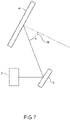
- an incidence angle 7 means an angle which the surface of optical functional film 101 and light which comes into the surface of optical functional film 101 form.
- the incidence angle 7 is 90°.
- the incidence angle 7 is 80°. That is, in Fig. 6 , a configuration such that the gap between a slow axis angle in a display portion 9A and a slow axis angle in a display portion 9B is 5° or more and 20° or less is a preferable embodiment of the head-up display of the present invention.
- the gap between the slow axis angle in the display portion 9A and the slow axis angle in the display portion 9B be 7° or more and 13° or less, and it is further preferable that the gap be 9° or more and 11° or less.
- the present invention can improve a decrease in the polarized light conversion efficiency of the optical functional film due to the inclination of this incidence angle 7 by correcting the above-mentioned slow axes, and contributes to reduction in the formation of a double image.
- the lower limit of the angle which the slow axis at an incidence angle of 90° and the slow axis at an incidence angle of 80° form be 7°, it is further preferable that the lower limit be 8°, and it is particularly preferable that the lower limit be 9°.
- the upper limit of the angle which the slow axis at an incidence angle of 90° and the slow axis at an incidence angle of 80° form be 19°, it is further preferable that the lower limit be 18°, and it is particularly preferable that the lower limit be 17°. That is, it is the most preferable that the angle which the slow axis at an incidence angle of 90° and the slow axis at an incidence angle of 80° form be 8° or more and 17° or less.
- the lower limit of the angle which the slow axis at an incidence angle of 90° and the slow axis at an incidence angle of 70° form be 14°, and it is particularly preferable that the lower limit be 16°.
- the upper limit of the angle which the slow axis at an incidence angle of 90° and the slow axis at an incidence angle of 70° form be 28°, and it is particularly preferable that the upper limit be 24°. That is, it is the most preferable that the angle which the slow axis at an incidence angle of 90° and the slow axis at an incidence angle of 70° form be 16° or more and 24° or less.
- an incidence angle 8 at which light emitted from a display image projecting means 2 comes into functional glass 4 as a display medium be in the range of ⁇ -10° to ⁇ +10°, and it is more preferable that the incidence angle 8 be the range of ⁇ -5° to ⁇ +5°.
- a display image projecting means 2 comes into functional glass 4 as a display medium
- the incidence angle 8 means an angle which the axis perpendicular to the surface of a display medium (functional glass 4) and light which comes into the surface of the display medium form (this incidence angle is also hereinafter referred to as an "incidence angle X").
- a 1/2 wavelength plate is used as an optical functional film
- a display medium is functional glass 4
- display light emitted from a display image projecting means 2 is S polarized light
- the reflection of P polarized light into which the S polarized light is converted by the functional glass 4 on a glass plate on the outer side of a car can be suppressed by making the S polarized light emitted from the display image projecting means 2 come in in the range of ⁇ -10° to ⁇ +10°, namely at an incidence angle 8 near the Brewster angle, preferably at an incidence angle 8 of the Brewster angle ⁇ , to the axis perpendicular to the surface of functional glass 4 through a reflecting mirror 3, and the formation of a double image can be deterred.
- the incidence angle 8 of the S polarized light is less than ⁇ -10° or more than ⁇ +10°, the incidence angle 8 of the S polarized light is not near the Brewster angle, the reflection of the P polarized light into which the S polarized light is converted by the 1/2 wavelength plate therefore increases, and a double image may be formed.
- a laminate in which one or more circularly polarized light reflecting layers (cholesteric liquid crystal layers) are clamped with two 1/4 wavelength plates is used as an optical functional film, an display medium is functional glass 4, and display light emitted from a display image projecting means 2 is P polarized light, the result is the same. Since reflected light from the road surface is generally S polarized light, polarization sunglasses are designed to be able to absorb S polarized light. In a conventional HUD system using S polarized light, the visibility of the display image in the HUD through polarization sunglasses therefore decreases extremely.
- the formation of a double image can be suppressed, and the visibility of the display image can be enhanced also when the polarization sunglasses are worn.
- the circularly polarized light reflecting layer is a cholesteric liquid crystal layer
- circularly polarized light transmitted through the circularly polarized light reflecting layer is converted into the original P polarized light by the second 1/4 wavelength plate in which the slow axis is disposed so as to intersect at right angles to the slow axis of the first 1/4 wavelength plate.
- the converted P polarized light comes into the glass surface on the outer side of the car and outside the second 1/4 wavelength plate near the Brewster angle in the same way. Therefore, the reflection of the P polarized light on the glass surface on the outer side of the car and outside the second 1/4 wavelength plate can also be reduced greatly, and the formation of a double image is consequently improved greatly.
- the angle ⁇ which the slow axis of the optical functional film forms with the polarization axis of S polarized light or the polarization axis of P polarized light which comes in from an oblique position at 45° or more and 65° or less to the axis perpendicular to the surface of the functional glass be controlled to 35° or more and 47° or less to convert polarized light (to convert P polarized light into S polarized light or convert S polarized light into P polarized light) efficiently.
- the reflectance on the surface of the functional glass can be theoretically suppressed to 2% or less by adjusting the incidence angle of S polarized light or P polarized light which comes into the functional glass to the range of 45° or more and 65° or less.
- Transmitted P polarized light is converted into S polarized light with the 1/2 wavelength plate, and the converted S polarized light is reflected on the interface between the functional glass on the side opposite to the incidence side and air.
- the reflected S polarized light is converted into P polarized light with the 1/2 wavelength plate again, and this P polarized light reaches an observer.
- the angle ⁇ is less than 35° or more than 47°, the polarization axis conversion performance for converting P polarized light which comes into the functional glass into S polarized light or converting S polarized light which comes into the functional glass into P polarized light is low, and a double image may consequently be formed.
- the 1/2 wavelength plate exhibits good polarization axis conversion performance by controlling this angle ⁇ appropriately, and the display image can be consequently visually confirmed more clearly.
- the angle ⁇ be a value calculated from the following Expressions (2) and (3) to appropriately control the conversion performance of the polarization axis when the optical functional film includes a 1/2 wavelength plate.
- the technical meaning of the following Expressions (2) and (3) will be described.
- the incidence angle X which S polarized light or P polarized light forms with the functional glass is defined as ⁇
- the incidence angle X at which the S polarized light or the P polarized light actually comes into the 1/2 wavelength plate, namely the refraction angle of the 1/2 wavelength plate is defined as ⁇
- the refractive index of air is defined as n ⁇
- the refractive index of the 1/2 wavelength plate is defined as n ⁇
- a phase difference value when the polarization axis of S polarized light which comes into the functional glass is defined as the x-axis
- the polarization axis of P polarized light is the y-axis
- an angle which the y-axis and the slow axis of the 1/2 wavelength plate form is defined as ⁇ is Re
- the y-axis is represented by Re•cos ⁇
- the x-axis is represented by Re•sin ⁇ using vector analysis.
- the incidence angle ⁇ which the polarization axis of S polarized light or the polarization axis of P polarized light and the slow axis of the optical functional film form be theoretically 45°.
- ⁇ an angle which the polarization axis of S polarized light or P polarized light which comes into the functional glass and the slow axis of the optical functional film form.
- the polarization axis conversion performance which the 1/2 wavelength plate exhibits can be utilized to the utmost by controlling the angle ⁇ strictly using the relationship with the angle ⁇ at which the S polarized light or the P polarized light actually comes into the 1/2 polarizing plate based on a value calculated from the following Expressions (2) and (3).
- the range of the angle ⁇ be controlled to the range of the value of the angle ⁇ ⁇ 5°, and it is more preferable that the range of the angle ⁇ be controlled to the range of the value of the angle ⁇ ⁇ 3°.
- the angle ⁇ is out of the range of an angle which satisfies a value calculated from Expressions (2) and (3) ⁇ 5°, the polarization light conversion efficiency which the 1/2 wavelength plate exhibits decreases. A decrease in the polarization light conversion efficiency with the 1/2 wavelength plate can be suppressed by controlling the range of the angle ⁇ based on the value calculated from Expressions (2) and (3).
- the refractive index in the direction of the slow axis of the 1/2 wavelength plate is defined as nx
- the refractive index in the direction at right angles to nx in the plane of the 1/2 wavelength plate is defined as ny
- the refractive index in the thickness direction of the 1/2 wavelength plate is defined as nz
- a value obtained by averaging these is used as an average refractive index.
- the range of ⁇ is preferably 37° or more and 47° or less, and more preferably 39° or more and 45° or less.
- the incidence angle X of S polarized light or P polarized light is 50°
- the value of ⁇ is 41° based on Expressions (2) and (3). Therefore, it is preferable that the range of ⁇ be 36° or more and 46° or less, and it is more preferable that the range be 38° or more and 44° or less.
- the incidence angle X of S polarized light or P polarized light is 56° or 60°
- the value of ⁇ is 40° based on Expressions (2) and (3).
- the range of ⁇ be 35° or more and 45° or less, and it is more preferable that the range be 37° or more and 43° or less. Furthermore, when the incidence angle X of S polarized light or P polarized light is 65°, the value of ⁇ is 39° based on Expressions (2) and (3). Therefore, it is preferable that the range of ⁇ be 34° or more and 44° or less, and it is more preferable that the range be 36° or more and 42° or less.
- the polarization axis conversion performance which 1/2 wavelength plate exhibits can be further improved by controlling the angle ⁇ which the polarization axis of S polarized light or P polarized light which comes into an optical functional film and the slow axis of the 1/2 wavelength plate form.
- a 1/2 wavelength plate including a polymerizable liquid crystal layer as a layer having the action of converting a polarization axis from the viewpoints of the controllability of the slow axis of the 1/2 wavelength plate and manufacturing cost.
- the wavelength dispersibility of the 1/2 wavelength plate as described above is suitable for a head-up display use, the wavelength dispersibility is not particularly limited.
- the 1/2 wavelength plate have reverse wavelength dispersibility.
- polymers generally have the normal dispersion, in which the absolute value of the birefringence increases on the short wavelength side, reverse wavelength dispersibility is obtained in the case of a liquid crystal compound such that the birefringence increases on the long wavelength side by controlling the value of the birefringence ⁇ n at each wavelength of visible light.
- Reverse wavelength dispersibility is also obtained by lamination in the combination of suitable slow axes of a plurality of phase difference plates having suitable phase difference values according to the wavelength dispersion characteristic of a compound.
- the 1/2 wavelength plate When the 1/2 wavelength plate by lamination in combination of such a plurality of phase difference plates is used, the 1/2 wavelength plate exhibits good polarization axis conversion performance by controlling the angle ⁇ which the polarization axis of S polarized light or P polarized light which comes into the optical functional film and the slow axis of the 1/2 wavelength plate form appropriately as to the slow axis angle of each phase difference plate as described above, and a display image can be consequently visually confirmed further clearly.
- part means “part by mass”.
- room temperature is in the range of 20°C ⁇ 5°C.
- a coating liquid (R1) which has a composition shown in Table 1, was prepared.
- coating liquids (R2), (R3), and (R4) were prepared by the same prescription, respectively, except that the prescribed amount of the chiral agent in the coating liquid (R1) was changed into the prescribed amounts shown in Table 2.
- Coating liquid Chiral agent Prescribed amount (part) Coating liquid (R2) 1.26 Coating liquid (R3) 1.04 Coating liquid (R4) 0.70
- QWP coating liquid
- Table 3 Material (type) Material name (maker name) Prescribed amount (part) Nematic liquid crystal monomer LC242 (BASF Japan Ltd.) 24.69 Photopolymerization initiator IrgacureTPO (BASF Japan Ltd.) 1.23 Solvent Cyclopentanone 74.07
- a light reflecting layer PRL-1, a light reflecting layer PRL-2, a light reflecting layer PRL-3, and a light reflecting layer PRL-4 were manufactured in the following procedure using the prepared coating liquids (R1), (R2), (R3), and (R4), respectively. Subsequently, they were laminated to manufacture a circularly polarized light reflecting layer. Subsequently, 1/4 wavelength plates were further laminated on both surfaces of the obtained circularly polarized light reflecting layer to manufacture an optical control laminate.
- UV irradiation was performed with a high-pressure mercury lamp (manufactured by HARISON TOSHIBA LIGHTING Corporation) at a generating power of 120 W for 5 to 10 seconds, the cholesteric liquid crystal phases were fixed to manufacture cholesteric liquid crystal layers based on the coating liquids (R1), (R2), (R3), and (R4), namely a light reflecting layer PRL-1, a light reflecting layer PRL-2, a light reflecting layer PRL-3, and a light reflecting layer PRL-4, were formed on the PET films, respectively.
- a high-pressure mercury lamp manufactured by HARISON TOSHIBA LIGHTING Corporation
- the coating liquid shown in Table 3 was applied to the rubbing-treated surfaces of the PET films at room temperature using the wire bar so that the thicknesses of the 1/4 wavelength plates obtained after drying were 1 ⁇ m.
- the surface of each PET film was subsequently divided into three regions which were P, Q, and R each having a width of 20 cm in the width direction from the left, a rubbing angle was set up so that an angle which the axis in the length direction (vertical axis) of the PET film and the slow axis of the 1/4 wavelength plate form was a predetermined angle in each region as shown in Table 4, and rubbing treatment was performed.
- the length direction is, for example, a longitudinal direction (short side) in Fig. 2
- the width direction is a transverse direction (long side).
- UV irradiation was performed with a high-pressure mercury lamp (manufactured by HARISON TOSHIBA LIGHTING Corporation) at a generating power of 120 W for 5 to 10 seconds, and the liquid crystal phases were fixed to manufacture a total of 14 1/4 wavelength plates in which the polymerizable liquid crystal layers were formed on the PET films and which have predetermined slow axis zones.
- the 1/4 wavelength plates were cut to a size having a width of 60 cm in the width direction and a length of 50 cm in the length direction and including all of the regions P, Q, and R.
- the slow axis zones which were the regions P, Q, and R each having a width of 20 cm in the width direction from the left are formed in the same plane (, and matched the areas shown in Table 4).
- the phase difference values of the regions of the obtained 1/4 wavelength plates were measured with an automatic birefringence meter ("KOBRA-21ADH" manufactured by Oji Scientific Instruments Co., Ltd.), and all the phase difference values at 546 nm were 136 nm.
- the light reflecting layer sides of the light reflecting layer PRL-1 (the coating liquid (R1) was used) and the light reflecting layer PRL-2 (the coating liquid (R2) was used) on the PET films manufactured at (1) to (2) were laminated using an acrylic pressure sensitive adhesive (produced by Soken Chemical & Engineering Co., Ltd., acrylics adhesive SK Dyne 906).
- the PET film on the light reflecting layer PRL-2 was exfoliated.
- the light reflecting layer side of the light reflecting layer PRL-3 (the coating liquid (R3) was used) on the PET film manufactured at (1) to (2) and the light reflecting layer PRL-2 at (6) were laminated on the light reflecting layer sides from which the PET films were exfoliated using the same acrylic pressure sensitive adhesive as the adhesive used at (5).
- the light reflecting layer side of the light reflecting layer PRL-4 (the coating liquid (R4) was used) was laminated on the light reflecting layer PRL-3 by the same method as at (7).
- the PET film outside the light reflecting layer PRL-1 and The PET film outside the PRL-4 were exfoliated to manufacture a circularly polarized light reflecting layer including four cholesteric liquid crystal layers.
- Fig. 8 is a figure obtained by plotting the relationship between the wavelength and the reflectance of the light reflecting layers when the single light reflecting layers PRL-1, PRL-2, PRL-3, and PRL-4 are formed. As shown in Fig.
- the central reflection wavelengths of the light reflecting layer PRL-1, PRL-2, PRL-3, and PRL-4 were 450 nm (the half breadth was 123 nm), 540 nm (the half breadth was 131 nm), 650 nm (the half breadth was 148 nm), and 800 nm (the half breadth was 178 nm), respectively, and the reflectances at the central reflection wavelengths of the light reflecting layers PRL-1, PRL2, PRL-3, and PRL-4 were around 20%, around 21%, around 22%, and around 20%, respectively.
- the average transmittance of the visible light in the obtained light reflecting layers in the front direction was around 77%, and the reflectances near 550 nm were around 22%. Even though each of the obtained light reflecting layers was seen from the position oblique to the front at 50°, there was no change in the transmittance in the red region, and each of the light reflecting layers had the same color tone as from the front direction.
- the phase difference value when each of the light reflecting layers was inclined at 50° was measured with an automatic birefringence meter ("KOBRA-21ADH" manufactured by Oji Scientific Instruments Co., Ltd.), and the phase difference value at 546 nm was consequently 55 nm.
- Transparent polyvinyl butyral intermediate films having a thickness of 0.38 mm and containing triethylene glycol di-2-ethylhexanoate as a plasticizer were cut out to the same size as the manufactured optical functional film.
- the manufactured optical functional film was disposed between the two polyvinyl butyral intermediate films. Subsequently, the optical functional film and the two polyvinyl butyral intermediate films were pressurized and press-fit with a laminator to manufacture an optical laminate.
- the above-mentioned optical laminate was disposed between two glass plates each having the same size as the manufactured optical laminate and a thickness of 2 mm, and pressurization and heating are subsequently performed to manufacture functional glass.
- the above-mentioned optical laminate and a transparent glass plate were laid on a transparent glass plate sequentially. This was wrapped in a rubber bag, deaerated in an autoclave heated at 90°C for 10 minutes, and subjected to preliminary adhesion. This was cooled to room temperature, and this was then taken out of the rubber bag, and heated and pressurized in the autoclave at 135°C under a high pressure of 12 kg/cm 2 for 30 minutes again. Functional glass which had good appearance and in which the optical laminate was inserted was manufactured. The visible light transmittance of the obtained functional glass was 72%.
- a head-up display was manufactured in the disposition as shown in Fig. 5 .
- a liquid crystal display panel which can emit P polarized light to the functional glass 4 was installed.
- the functional glass 4 the functional glass manufactured above was used.
- the width direction of the optical functional film in the configuration of the functional glass 4 was adjusted so that P polarized light emitted from the display image projecting means 2 came in with the incidence angle X of the P polarized light adjusted to the Brewster angle (around 56°) to the functional glass 4 in a darkroom.
- the glass on the 1/4 wavelength plate side including Y-4 in Table 4 was installed on a side into which P polarized light from the display image projecting means comes, and an image was projected, the display image was projected brightly and clearly.
- a line drawing image was projected on the functional glass 4 under the condition that the line drawing image was emitted from an image projection device (display image projecting means 2) in P polarized light in the disposition shown in Fig. 7 .
- the reflected image was photographed with a color brightness meter manufactured by KONICA MINOLTA, INC. (Prometric IC-PMI), and the display picture was evaluated.
- the evaluation image at the position I was photographed from a point X which is 142 cm away from the glass surface perpendicularly to the glass surface with the position I defined as the starting point.
- the evaluation image at the position II was photographed from a position oblique to a perpendicular line from the point X to the position I at 10° to right with a brightness meter.
- the evaluation image at the position III was photographed from a position oblique to a perpendicular line from the point X to the position I at 15° to right with a brightness meter.
- the double image brightness ratio was calculated by multiplying a numerical value obtained by dividing the reflection brightness of the line drawing image on the optical functional film plane (the main image) by the reflection brightness of the line drawing image on the air interface of the glass on the side opposite to the image projection device (double image) in the configuration of functional glass by 100 by the analysis of the photographed images at the positions.
- the results are shown in Table 6. It can be determined that if the double image bright ratio shown in Table 6 is lower, the image projected on functional glass is hardly visually confirmed doubly, and the visibility of the image is good.
- An optical functional film, an optical laminate, and functional glass were manufactured in the same way as in Example 1 except that 1/4 wavelength plates in which the slow axis angles in the regions P, Q, and R exhibited X-5 and Y-5 in Table 4, respectively, were laminated on both surfaces of the circularly polarized light reflecting layer as to polymerizable liquid crystal layers on PET films manufactured at the above-mentioned (3) to (4).
- the double image brightness ratio was evaluated in the same way using the obtained functional glass. The results are shown in Table 6.
- An optical functional film, an optical laminate, and functional glass were manufactured in the same way as in Example 1 except that 1/4 wavelength plates in which the slow axis angles in the regions P, Q, and R exhibited X-6 and Y-6 in Table 4, respectively, were laminated on both surfaces of the circularly polarized light reflecting layer as to polymerizable liquid crystal layers on PET films manufactured at the above-mentioned (3) to (4).
- the double image brightness ratio was evaluated in the same way using the obtained functional glass. The results are shown in Table 6.
- An optical functional film, an optical laminate, and functional glass were manufactured in the same way as in Example 1 except that 1/4 wavelength plates in which the slow axis angles in the regions P, Q, and R exhibited X-3 and Y-3 in Table 4, respectively, were laminated on both surfaces of the circularly polarized light reflecting layer as to polymerizable liquid crystal layers on PET films manufactured at the above-mentioned (3) to (4).
- the double image brightness ratio was evaluated in the same way using the obtained functional glass. The results are shown in Table 6.
- An optical functional film, an optical laminate, and functional glass were manufactured in the same way as in Example 1 except that 1/4 wavelength plates in which the slow axis angles in the regions P, Q, and R exhibited X-1 and Y-1 in Table 4, respectively, were laminated on both surfaces of the circularly polarized light reflecting layer as to polymerizable liquid crystal layers on PET films manufactured at the above-mentioned (3) to (4).
- the double image brightness ratio was evaluated in the same way using the obtained functional glass. The results are shown in Table 6.
- An optical functional film, an optical laminate, and functional glass were manufactured in the same way as in Example 1 except that 1/4 wavelength plates in which the slow axis angles in the regions P, Q, and R exhibited X-2 and Y-2 in Table 4, respectively, were laminated on both surfaces of the circularly polarized light reflecting layer as to polymerizable liquid crystal layers on PET films manufactured at the above-mentioned (3) to (4).
- the double image brightness ratio was evaluated in the same way using the obtained functional glass. The results are shown in Table 6.
- An optical functional film, an optical laminate, and functional glass were manufactured in the same way as in Example 1 except that 1/4 wavelength plates in which the slow axis angles in the regions P, Q, and R exhibited X-7 and Y-7 in Table 4, respectively, were laminated on both surfaces of the circularly polarized light reflecting layer as to polymerizable liquid crystal layers on PET films manufactured at the above-mentioned (3) to (4).
- the double image brightness ratio was evaluated in the same way using the obtained functional glass. The results are shown in Table 6.
- the coating liquid shown in Table 3 was applied to the rubbing-treated surfaces of the PET films at room temperature using the wire bar at the above-mentioned (3) so that the thicknesses of 1/2 wavelength plates obtained after drying were around 2 ⁇ m, respectively.
- the surface of each PET film was divided into three regions which were P, Q, and R each having a width of 20 cm in the width direction from the left, a rubbing angle was set up so that an angle which the axis in the length direction (vertical axis) of the PET film and the slow axis of the 1/2 wavelength plate form was a predetermined angle in each region as shown in Table 7, and rubbing treatment was performed.
- the obtained coating films were heated at 80°C for 2 minutes, and the solvent was removed to form liquid crystal phases. Subsequently, UV irradiation was performed with a high-pressure mercury lamp (manufactured by HARISON TOSHIBA LIGHTING Corporation) at a generating power of 120 W for 5 to 10 seconds, and the liquid crystal phases were fixed to manufacture a total of 14 1/2 wavelength plates wherein the 1/2 wavelength plates are divided into the two types, an X group and a Y group, each including 7 1/2 wavelength plates, the polymerizable liquid crystal layers were formed on the PET films, and the 1/2 wavelength plates have predetermined slow axis zones.
- a high-pressure mercury lamp manufactured by HARISON TOSHIBA LIGHTING Corporation
- the 1/2 wavelength plates were cut to a size having a width of 60 cm in the width direction and a length of 50 cm in the length direction and including all of the regions P, Q, and R.
- the slow axis zones which are P, Q, and R each having a width of 20 cm in the width direction from the left were formed in the same plane (, and match the areas shown in Table 7).
- phase difference values of the regions of the obtained 1/2 wavelength plates were measured with an automatic birefringence meter ("KOBRA-21ADH" manufactured by Oji Scientific Instruments Co., Ltd.), so that the phase difference values of the 7 1/2 wavelength plates in the group X at 546 nm were 290 nm, and the phase difference values of the 71/2 wavelength plates in the group Y at 546 nm were 250 nm.
- the polymerizable liquid crystal layers of the 1/2 wavelength plates were laminated on each other with the same acrylic pressure sensitive adhesive as the pressure sensitive adhesive used in the above-mentioned (5) using the 1/2 wavelength plates in which the slow axis angles in the regions P, Q, and R exhibited X-4 and Y-4 in Table 4, respectively as the manufactured polymerizable liquid crystal layers on the PET films with the width directions aligned so that the combination of the regions in the width directions in the planes was the combination of the P exhibiting X-4 and the R exhibiting Y-4; the Q exhibiting X-4 and the Q exhibiting Y-4; and the R exhibiting X-4 and the P exhibiting Y-4. Subsequently, the PET films of the 1/2 wavelength plates were exfoliated to perform the following measurements and evaluations.
- Transparent polyvinyl butyral intermediate films having a thickness of 0.38 mm and containing triethylene glycol di-2-ethylhexanoate as a plasticizer were cut out to the same size as the manufactured two-layer 1/2 wavelength plate.
- the above-mentioned two-layer 1/2 wavelength plate was disposed between the two polyvinyl butyral intermediate films. Subsequently, the two-layer 1/2 wavelength plate and the two polyvinyl butyral intermediate films were pressurized and press-fit with a laminator to manufacture an optical laminate.
- the above-mentioned optical laminate was disposed between two glass plates each having the same size as the manufactured two-layer 1/2 wavelength plate and a thickness of 2 mm, and pressurization and heating are subsequently performed to obtain functional glass.
- the above-mentioned optical laminate and a transparent glass plate were laid on a transparent glass plate sequentially. This was wrapped in a rubber bag, deaerated in an autoclave heated at 90°C for 10 minutes, and subjected to preliminary adhesion. This was cooled to room temperature, and this was then taken out of the rubber bag, and heated and pressurized in the autoclave at 135°C under a high pressure of 12 kg/cm 2 for 30 minutes again. Functional glass which had good appearance and in which the optical laminate was inserted was manufactured. The average transmittance of the obtained functional glass in the visible light region in the front direction (incidence angle: 56°) was around 72%. The polarized light transmittance was around 6%.
- a head-up display was manufactured in the disposition as shown in Fig. 5 .
- a liquid crystal display panel which can emit S polarized light to the functional glass 4 was installed.
- the functional glass 4 the functional glass manufactured above was used.
- the width direction of the optical functional film in the configuration of the functional glass 4 was adjusted so that S polarized light emitted from the display image projecting means 2 came in with the incidence angle X of the S polarized light adjusted to the Brewster angle (around 56°) to the functional glass 4 in a darkroom.
- the glass on the 1/2 wavelength plate side including the Y group in Table 7 was installed on a side on which S polarized light was emitted from the display image projecting means, and an image was projected, the display image was projected brightly and clearly.
- a line drawing image was projected on the functional glass 4 under the condition that the line drawing image was emitted from an image projection device (display image projecting means 2) in S polarized light in the disposition shown in Fig. 7 .
- the reflected image was photographed with a color brightness meter manufactured by KONICA MINOLTA, INC. (Prometric IC-PMI), and the display image was evaluated.
- the evaluation image at the position I was photographed from a point X which is 142 cm away from the glass surface perpendicularly to the glass surface with the position I defined as the starting point.
- the evaluation image at the position II was photographed from a position oblique to a perpendicular line from the point X to the position I at 10° to right with a brightness meter.
- the evaluation image at the position III was photographed from a position oblique to the perpendicular line from the point X to the position I at 15° to right with a brightness meter.
- the double image brightness ratio was calculated by multiplying a numerical value obtained by dividing the reflection brightness of the line drawing image on the air interface of the glass on the image projection device side (the main image) by the reflection brightness of the line drawing image on the air interface of the glass on the side opposite to the image projection device (double image) in the configuration of functional glass by 100 by the analysis of the photographed images at the positions.
- the results are shown in Table 8. It can be determined that if the double image bright ratio shown in Table 8 is lower, the image projected on functional glass is hardly visually confirmed doubly, and the visibility of the image is good.
- An optical functional film, an optical laminate, and functional glass were manufactured in the same way as in Example 5 except that 1/2 wavelength plates in which the slow axis angles in the regions P, Q, and R exhibited X-5 and Y-5 in Table 7, respectively, were laminated as to polymerizable liquid crystal layers on PET films.
- the double image brightness ratio was evaluated in the same way using the obtained functional glass. The results are shown in Table 8.
- An optical functional film, an optical laminate, and functional glass were manufactured in the same way as in Example 5 except that 1/2 wavelength plates in which the slow axis angles in the regions P, Q, and R exhibited X-6 and Y-6 in Table 7, respectively, were laminated as to polymerizable liquid crystal layers on PET films.
- the double image brightness ratio was evaluated in the same way using the obtained functional glass. The results are shown in Table 8.
- An optical functional film, an optical laminate, and functional glass were manufactured in the same way as in Example 5 except that 1/2 wavelength plates in which the slow axis angles in the regions P, Q, and R exhibited X-3 and Y-3 in Table 7, respectively, were laminated as to polymerizable liquid crystal layers on PET films.
- the double image brightness ratio was evaluated in the same way using the obtained functional glass. The results are shown in Table 8.
- An optical functional film, an optical laminate, and functional glass were manufactured in the same way as in Example 5 except that 1/2 wavelength plates in which the slow axis angles in the regions P, Q, and R exhibited X-1 and Y-1 in Table 7, respectively, were laminated as to polymerizable liquid crystal layers on PET films.
- the double image brightness ratio was evaluated in the same way using the obtained functional glass. The results are shown in Table 8.
- An optical functional film, an optical laminate, and functional glass were manufactured in the same way as in Example 5 except that 1/2 wavelength plates in which the slow axis angles in the regions P, Q, and R exhibited X-2 and Y-2 in Table 7, respectively, were laminated as to polymerizable liquid crystal layers on PET films.
- the double image brightness ratio was evaluated in the same way using the obtained functional glass. The results are shown in Table 8.
- An optical functional film, an optical laminate, and functional glass were manufactured in the same way as in Example 5 except that 1/2 wavelength plates in which the slow axis angles in the regions P, Q, and R exhibited X-7 and Y-7 in Table 7, respectively, were laminated as to polymerizable liquid crystal layers on PET films.
- the double image brightness ratio was evaluated in the same way using the obtained functional glass. The results are shown in Table 8.
- the coating liquid shown in Table 3 was applied to the rubbing-treated surfaces of the PET films at room temperature using the wire bar at the above-mentioned (3) so that the thicknesses of 1/2 wavelength plates obtained after drying were around 2 ⁇ m, respectively.
- the surface of each PET film was divided into three regions which were P, Q, and R each having a width of 20 cm in the width direction from the left, a rubbing angle was set up so that an angle which the axis in the length direction (vertical axis) of the PET film and the slow axis of the 1/2 wavelength plate form was a predetermined angle in each region as shown in Table 9, and rubbing treatment was performed.
- Example 10 Example 11 X (°) 1 2 3 4 5 6 P 50.0 50.0 50.0 50.0 50.0 50.0 Q 50.0 50.0 52.0 55.0 58.0 52.0 R 50.0 55.0 63.0 60.0 63.0 57.0
- the obtained coating films were heated at 80°C for 2 minutes, and the solvent was removed to form liquid crystal phases. Subsequently, UV irradiation was performed with a high-pressure mercury lamp (manufactured by HARISON TOSHIBA LIGHTING Corporation) at a generating power of 120 W for 5 to 10 seconds, and the liquid crystal phases were fixed to manufacture a total of 7 1/2 wavelength plates in which the polymerizable liquid crystal layers were formed on the PET films and which have predetermined slow axis zones. The 1/2 wavelength plates were cut to a size having a width of 60 cm in the width direction and a length of 50 cm in the length direction and including all of the regions P, Q, and R.
- the polymerizable liquid crystal layer of a 1/2 wavelength plate was pasted on a flat glass plate having the same size as the 1/2 wavelength plate and a thickness of 2 mm with the same acrylic pressure sensitive adhesive as the pressure sensitive adhesive used at the above-mentioned (5) applied to the polymerizable liquid crystal layer using the 1/2 wavelength plate in which the slow axis angles in the regions P, Q, and R exhibited X-4 in Table 9, respectively as the manufactured polymerizable liquid crystal layer on the PET film. Subsequently, the PET film of the 1/2 wavelength plate was exfoliated to perform the following measurements and evaluations.
- An optical functional film including one 1/2 wavelength plate was thus manufactured.
- the spectral characteristics of the natural light transmittance and the polarized light transmittance of the obtained 1/2 wavelength plate were measured, and the results are shown in Fig. 10 .
- the average transmittance in the visible light wavelength region in the front direction (incidence angle: 56°) was around 84%, and the polarized light transmittance was around 18%.
- the polarized light transmittance was measured using the "ultraviolet, visible, and near-infrared spectrophotometer UV-3600" manufactured by SHIMADZU CORPORATION with the 1/2 wavelength plate set between paralleled polarizing plates so that the incidence angle was 56°.
- a transparent polyvinyl butyral intermediate film having a thickness of 0.38 mm and containing triethylene glycol di-2-ethylhexanoate as a plasticizer was cut out to the same size as the manufactured 1/2 wavelength plate.
- the one polyvinyl butyral intermediate film was disposed on the polymerizable liquid layer side of the above-mentioned 1/2 wavelength plate. Subsequently, the 1/2 wavelength plate and the polyvinyl butyral intermediate film were pressurized and press-fit with a laminator to obtain an optical laminate.
- the polyvinyl butyral intermediate film side of the manufactured optical laminate was disposed on one glass plate having the same size as the 1/2 wavelength plate and a thickness of 2 mm, and pressurization and heating are subsequently performed to obtain functional glass.
- the above-mentioned optical laminate was laid on a transparent glass plate. This was wrapped in a rubber bag, deaerated in an autoclave heated at 90°C for 10 minutes, and subjected to preliminary adhesion. This was cooled to room temperature, and this was then taken out of the rubber bag, and heated and pressurized in the autoclave at 135°C under a high pressure of 12 kg/cm 2 for 30 minutes again.
- Functional glass which had good appearance and in which the optical laminate was inserted was manufactured.
- the average transmittance of the obtained functional glass in the visible light region in the front direction (incidence angle: 56°) was around 73%.
- the polarized light transmittance was around 14%.
- a head-up display was manufactured in the disposition as shown in Fig. 5 .
- a liquid crystal display panel which can emit S polarized light to the functional glass 4 was installed.
- the functional glass 4 the functional glass manufactured above was used.
- the width direction of the optical functional film in the configuration of the functional glass 4 was adjusted so that S polarized light emitted from the display image projecting means 2 came in with the incidence angle X of the S polarized light adjusted to the Brewster angle (around 56°) to the functional glass 4 in a darkroom.
- the glass on the 1/2 wavelength plate side including X-4 in Table 9 was installed on a side on which S polarized light was emitted from the display image projecting means, and an image was projected, the display image was projected brightly and clearly.
- a line drawing image was projected on the functional glass 4 under the condition that the line drawing image was emitted from an image projection device (display image projecting means 2) in S polarized light in the disposition shown in Fig. 7 .
- the reflected image was photographed with a color brightness meter manufactured by KONICA MINOLTA, INC. (Prometric IC-PMI), and the display image was evaluated.
- the evaluation image at the position I was photographed from a point X which is 142 cm away from the glass surface perpendicularly to the glass surface with the position I defined as the starting point.
- the evaluation image at the position II was photographed from a position oblique to a perpendicular line from the point X to the position I at 5° to right with a brightness meter.
- the evaluation image at the position III was photographed from a position oblique to a perpendicular line from the point X to the position I at 10° to right with a brightness meter.
- the double image brightness ratio was calculated by multiplying a numerical value obtained by dividing the reflection brightness of the line drawing image on the air interface of the glass on the image projection device side (the main image) by the reflection brightness of the line drawing image on the air interface of the glass on the side opposite to the image projection device (double image) in the configuration of functional glass by 100 by the analysis of the photographed images at the positions.
- the results are shown in Table 10. It can be determined that if the double image bright ratio shown in Table 10 is lower, the image projected on functional glass is hardly visually confirmed doubly, and the visibility of the image is good.
- An optical functional film, an optical laminate, and functional glass were manufactured in the same way as in Example 9 except that a 1/2 wavelength plate in which the slow axis angles in the regions P, Q, and R exhibited X-5 in Table 9, respectively, was used as to a polymerizable liquid crystal layer on a PET film.
- the double image brightness ratio was evaluated in the same way using the obtained functional glass. The results are shown in Table 10.
- An optical functional film, an optical laminate, and functional glass were manufactured in the same way as in Example 9 except that a 1/2 wavelength plate in which the slow axis angles in the regions P, Q, and R exhibited X-6 in Table 9, respectively, was used as to a polymerizable liquid crystal layer on a PET film.
- the double image brightness ratio was evaluated in the same way using the obtained functional glass. The results are shown in Table 10.
- An optical functional film, an optical laminate, and functional glass were manufactured in the same way as in Example 9 except that a 1/2 wavelength plate in which the slow axis angles in the regions P, Q, and R exhibited X-3 in Table 9, respectively, was used as to a polymerizable liquid crystal layer on a PET film.
- the double image brightness ratio was evaluated in the same way using the obtained functional glass. The results are shown in Table 10.
- An optical functional film, an optical laminate, and functional glass were manufactured in the same way as in Example 9 except that a 1/2 wavelength plate in which the slow axis angles in the regions P, Q, and R exhibited X-1 in Table 9, respectively, was used as to a polymerizable liquid crystal layer on a PET film.
- the double image brightness ratio was evaluated in the same way using the obtained functional glass. The results are shown in Table 10.
- An optical functional film, an optical laminate, and functional glass were manufactured in the same way as in Example 9 except that a 1/2 wavelength plate in which the slow axis angles in the regions P, Q, and R exhibited X-2 in Table 9, respectively, was used as to a polymerizable liquid crystal layer on a PET film.
- the double image brightness ratio was evaluated in the same way using the obtained functional glass. The results are shown in Table 10.
- a head-up display system including an optical functional film of the present invention can remove the unevenness of the formation of a double image depending on the projection position, namely, can suppress the formation of a double image independently of the photographing position. Therefore, viewers can use the head-up display system without stress.
Landscapes
- Physics & Mathematics (AREA)
- Optics & Photonics (AREA)
- General Physics & Mathematics (AREA)
- Engineering & Computer Science (AREA)
- Chemical & Material Sciences (AREA)
- Transportation (AREA)
- Mechanical Engineering (AREA)
- Combustion & Propulsion (AREA)
- Crystallography & Structural Chemistry (AREA)
- Polarising Elements (AREA)
- Laminated Bodies (AREA)
- Joining Of Glass To Other Materials (AREA)
- Instrument Panels (AREA)
- Liquid Crystal (AREA)
Applications Claiming Priority (2)
| Application Number | Priority Date | Filing Date | Title |
|---|---|---|---|
| JP2020013130 | 2020-01-30 | ||
| PCT/JP2021/003333 WO2021153763A1 (ja) | 2020-01-30 | 2021-01-29 | ヘッドアップディスプレイ用光学機能フィルム、光学積層体、機能性ガラス、およびヘッドアップディスプレイシステム |
Publications (2)
| Publication Number | Publication Date |
|---|---|
| EP4099084A1 true EP4099084A1 (de) | 2022-12-07 |
| EP4099084A4 EP4099084A4 (de) | 2024-02-21 |
Family
ID=77078278
Family Applications (1)
| Application Number | Title | Priority Date | Filing Date |
|---|---|---|---|
| EP21746935.2A Pending EP4099084A4 (de) | 2020-01-30 | 2021-01-29 | Optischer funktionsfilm für head-up display, optisches laminat, funktionsglas und head-up display system |
Country Status (5)
| Country | Link |
|---|---|
| US (1) | US20220357494A1 (de) |
| EP (1) | EP4099084A4 (de) |
| JP (2) | JP7045525B2 (de) |
| CN (1) | CN115004083B (de) |
| WO (1) | WO2021153763A1 (de) |
Families Citing this family (4)
| Publication number | Priority date | Publication date | Assignee | Title |
|---|---|---|---|---|
| WO2023054324A1 (ja) * | 2021-09-30 | 2023-04-06 | 富士フイルム株式会社 | ヘッドアップディスプレイシステム及び輸送機 |
| WO2024219441A1 (ja) * | 2023-04-18 | 2024-10-24 | 日本化薬株式会社 | 機能性ガラス及びヘッドアップディスプレイシステム |
| JPWO2024232319A1 (de) * | 2023-05-09 | 2024-11-14 | ||
| WO2025159009A1 (ja) * | 2024-01-24 | 2025-07-31 | 富士フイルム株式会社 | 反射フィルム、ヘッドアップディスプレイシステム |
Family Cites Families (18)
| Publication number | Priority date | Publication date | Assignee | Title |
|---|---|---|---|---|
| JP2958418B2 (ja) | 1992-07-23 | 1999-10-06 | セントラル硝子株式会社 | 表示装置 |
| GB2331812A (en) * | 1997-11-26 | 1999-06-02 | Sharp Kk | Optical retardation devices |
| JP3568412B2 (ja) * | 1999-03-02 | 2004-09-22 | セントラル硝子株式会社 | 表示装置 |
| JP2002090743A (ja) | 2000-07-13 | 2002-03-27 | Nippon Kayaku Co Ltd | ラビング方法 |
| JP3960549B2 (ja) | 2002-02-19 | 2007-08-15 | 日東電工株式会社 | Va型液晶セル用光学補償機能付き偏光板およびva型液晶セル用光学補償機能層 |
| EP1376163B1 (de) | 2002-06-27 | 2011-08-17 | Merck Patent GmbH | Verfahren zur Schichtherstellung mit polymerisierten Flüssigkristallmaterialien |
| JP2009271463A (ja) * | 2008-05-12 | 2009-11-19 | Fujifilm Corp | 液晶表示装置及び液晶セル |
| US20100060985A1 (en) * | 2008-09-09 | 2010-03-11 | Fujifilm Corporation | Method for producing polarizing plate, and automobile's windshield |
| JP5170207B2 (ja) * | 2010-10-20 | 2013-03-27 | 株式会社Jvcケンウッド | 分布型補償器および投射型液晶表示装置 |
| JP2012163786A (ja) * | 2011-02-07 | 2012-08-30 | Jvc Kenwood Corp | 分布型偏光子および投射型液晶表示装置 |
| JP5922459B2 (ja) * | 2012-03-26 | 2016-05-24 | 株式会社有沢製作所 | 位相差板の製造方法 |
| KR101869369B1 (ko) * | 2014-10-10 | 2018-06-21 | 니폰 가야꾸 가부시끼가이샤 | 광반사 필름, 및 이를 이용한 광제어 필름, 광학 필름, 기능성 유리 및 헤드업 디스플레이 |
| WO2017169968A1 (ja) * | 2016-03-30 | 2017-10-05 | 富士フイルム株式会社 | 光学積層フィルムおよび偏光イメージングセンサ |
| JP6821492B2 (ja) * | 2016-04-08 | 2021-01-27 | 日本化薬株式会社 | 光反射フィルム、ならびにこれを用いた光学フィルム、機能性ガラスおよびヘッドアップディスプレイ |
| JP2018017839A (ja) * | 2016-07-27 | 2018-02-01 | 日本化薬株式会社 | 機能性ガラスおよびこれを用いたヘッドアップディスプレイ |
| US11156814B2 (en) * | 2017-03-31 | 2021-10-26 | 3M Innovative Properties Company | Optical system for displaying an object to a viewer |
| JP6858113B2 (ja) * | 2017-05-29 | 2021-04-14 | 富士フイルム株式会社 | 実像表示用部材、および表示システム |
| WO2019163969A1 (ja) * | 2018-02-23 | 2019-08-29 | 富士フイルム株式会社 | 画像表示用合わせガラスの製造方法、画像表示用合わせガラス、および、画像表示システム |
-
2021
- 2021-01-29 EP EP21746935.2A patent/EP4099084A4/de active Pending
- 2021-01-29 CN CN202180011390.0A patent/CN115004083B/zh active Active
- 2021-01-29 JP JP2021523532A patent/JP7045525B2/ja active Active
- 2021-01-29 WO PCT/JP2021/003333 patent/WO2021153763A1/ja not_active Ceased
-
2022
- 2022-03-16 JP JP2022041707A patent/JP2022089820A/ja active Pending
- 2022-07-15 US US17/812,805 patent/US20220357494A1/en not_active Abandoned
Also Published As
| Publication number | Publication date |
|---|---|
| CN115004083A (zh) | 2022-09-02 |
| JP7045525B2 (ja) | 2022-03-31 |
| WO2021153763A1 (ja) | 2021-08-05 |
| US20220357494A1 (en) | 2022-11-10 |
| EP4099084A4 (de) | 2024-02-21 |
| CN115004083B (zh) | 2025-03-11 |
| JP2022089820A (ja) | 2022-06-16 |
| JPWO2021153763A1 (de) | 2021-08-05 |
Similar Documents
| Publication | Publication Date | Title |
|---|---|---|
| JP6617082B2 (ja) | 光反射フィルム、ならびにこれを用いた光制御フィルム、光学フィルム、機能性ガラスおよびヘッドアップディスプレイ | |
| US10525666B2 (en) | Optical laminate structure and head-up display system using the optical laminate structure, and light reflection film | |
| US11294177B2 (en) | Head-up display system | |
| HK1245896A1 (zh) | 光反射膜及其制造方法、使用了该光反射膜的光控制膜、光学膜、功能性玻璃和平视显示器 | |
| US20220357494A1 (en) | Optical functional film for head-up display, optical laminate, functional glass, and head-up display system | |
| JP2018017839A (ja) | 機能性ガラスおよびこれを用いたヘッドアップディスプレイ | |
| US20250208410A1 (en) | Head-up display system and optical functional layer for head-up display | |
| JP7390292B2 (ja) | 部分旋光子、ならびにこれを用いた部分旋光フィルム、中間膜積層体、機能性ガラスおよびヘッドアップディスプレイ | |
| EP4169757B1 (de) | Optisches laminat für head-up-anzeige, funktionelles glas und head-up-anzeigesystem |
Legal Events
| Date | Code | Title | Description |
|---|---|---|---|
| STAA | Information on the status of an ep patent application or granted ep patent |
Free format text: STATUS: THE INTERNATIONAL PUBLICATION HAS BEEN MADE |
|
| PUAI | Public reference made under article 153(3) epc to a published international application that has entered the european phase |
Free format text: ORIGINAL CODE: 0009012 |
|
| STAA | Information on the status of an ep patent application or granted ep patent |
Free format text: STATUS: REQUEST FOR EXAMINATION WAS MADE |
|
| 17P | Request for examination filed |
Effective date: 20220721 |
|
| AK | Designated contracting states |
Kind code of ref document: A1 Designated state(s): AL AT BE BG CH CY CZ DE DK EE ES FI FR GB GR HR HU IE IS IT LI LT LU LV MC MK MT NL NO PL PT RO RS SE SI SK SM TR |
|
| DAV | Request for validation of the european patent (deleted) | ||
| DAX | Request for extension of the european patent (deleted) | ||
| STAA | Information on the status of an ep patent application or granted ep patent |
Free format text: STATUS: EXAMINATION IS IN PROGRESS |
|
| A4 | Supplementary search report drawn up and despatched |
Effective date: 20240123 |
|
| RIC1 | Information provided on ipc code assigned before grant |
Ipc: B32B 7/12 20060101ALI20240117BHEP Ipc: B32B 5/14 20060101ALI20240117BHEP Ipc: G02B 5/30 20060101ALI20240117BHEP Ipc: C03C 27/12 20060101ALI20240117BHEP Ipc: B60K 35/00 20060101ALI20240117BHEP Ipc: B32B 17/10 20060101ALI20240117BHEP Ipc: B32B 7/023 20190101ALI20240117BHEP Ipc: G02B 27/01 20060101AFI20240117BHEP |
|
| 17Q | First examination report despatched |
Effective date: 20240205 |