EP4099126A2 - Systèmes et procédés de commande de déplacement de véhicule de manutention de matériaux basés sur la detection de la vitesse et de l'angle de braquage - Google Patents
Systèmes et procédés de commande de déplacement de véhicule de manutention de matériaux basés sur la detection de la vitesse et de l'angle de braquage Download PDFInfo
- Publication number
- EP4099126A2 EP4099126A2 EP22176368.3A EP22176368A EP4099126A2 EP 4099126 A2 EP4099126 A2 EP 4099126A2 EP 22176368 A EP22176368 A EP 22176368A EP 4099126 A2 EP4099126 A2 EP 4099126A2
- Authority
- EP
- European Patent Office
- Prior art keywords
- material handling
- handling vehicle
- speed
- scanner
- vehicle
- Prior art date
- Legal status (The legal status is an assumption and is not a legal conclusion. Google has not performed a legal analysis and makes no representation as to the accuracy of the status listed.)
- Granted
Links
Images





Classifications
-
- G—PHYSICS
- G05—CONTROLLING; REGULATING
- G05D—SYSTEMS FOR CONTROLLING OR REGULATING NON-ELECTRIC VARIABLES
- G05D1/00—Control of position, course, altitude or attitude of land, water, air or space vehicles, e.g. using automatic pilots
- G05D1/02—Control of position or course in two dimensions
- G05D1/021—Control of position or course in two dimensions specially adapted to land vehicles
- G05D1/0212—Control of position or course in two dimensions specially adapted to land vehicles with means for defining a desired trajectory
- G05D1/0223—Control of position or course in two dimensions specially adapted to land vehicles with means for defining a desired trajectory involving speed control of the vehicle
-
- G—PHYSICS
- G05—CONTROLLING; REGULATING
- G05D—SYSTEMS FOR CONTROLLING OR REGULATING NON-ELECTRIC VARIABLES
- G05D1/00—Control of position, course, altitude or attitude of land, water, air or space vehicles, e.g. using automatic pilots
- G05D1/02—Control of position or course in two dimensions
- G05D1/021—Control of position or course in two dimensions specially adapted to land vehicles
- G05D1/0231—Control of position or course in two dimensions specially adapted to land vehicles using optical position detecting means
- G05D1/0238—Control of position or course in two dimensions specially adapted to land vehicles using optical position detecting means using obstacle or wall sensors
- G05D1/024—Control of position or course in two dimensions specially adapted to land vehicles using optical position detecting means using obstacle or wall sensors in combination with a laser
-
- B—PERFORMING OPERATIONS; TRANSPORTING
- B66—HOISTING; LIFTING; HAULING
- B66F—HOISTING, LIFTING, HAULING OR PUSHING, NOT OTHERWISE PROVIDED FOR, e.g. DEVICES WHICH APPLY A LIFTING OR PUSHING FORCE DIRECTLY TO THE SURFACE OF A LOAD
- B66F9/00—Devices for lifting or lowering bulky or heavy goods for loading or unloading purposes
- B66F9/06—Devices for lifting or lowering bulky or heavy goods for loading or unloading purposes movable, with their loads, on wheels or the like, e.g. fork-lift trucks
- B66F9/063—Automatically guided
-
- B—PERFORMING OPERATIONS; TRANSPORTING
- B66—HOISTING; LIFTING; HAULING
- B66F—HOISTING, LIFTING, HAULING OR PUSHING, NOT OTHERWISE PROVIDED FOR, e.g. DEVICES WHICH APPLY A LIFTING OR PUSHING FORCE DIRECTLY TO THE SURFACE OF A LOAD
- B66F9/00—Devices for lifting or lowering bulky or heavy goods for loading or unloading purposes
- B66F9/06—Devices for lifting or lowering bulky or heavy goods for loading or unloading purposes movable, with their loads, on wheels or the like, e.g. fork-lift trucks
- B66F9/075—Constructional features or details
- B66F9/0755—Position control; Position detectors
-
- B—PERFORMING OPERATIONS; TRANSPORTING
- B66—HOISTING; LIFTING; HAULING
- B66F—HOISTING, LIFTING, HAULING OR PUSHING, NOT OTHERWISE PROVIDED FOR, e.g. DEVICES WHICH APPLY A LIFTING OR PUSHING FORCE DIRECTLY TO THE SURFACE OF A LOAD
- B66F9/00—Devices for lifting or lowering bulky or heavy goods for loading or unloading purposes
- B66F9/06—Devices for lifting or lowering bulky or heavy goods for loading or unloading purposes movable, with their loads, on wheels or the like, e.g. fork-lift trucks
- B66F9/075—Constructional features or details
- B66F9/07568—Steering arrangements
-
- B—PERFORMING OPERATIONS; TRANSPORTING
- B66—HOISTING; LIFTING; HAULING
- B66F—HOISTING, LIFTING, HAULING OR PUSHING, NOT OTHERWISE PROVIDED FOR, e.g. DEVICES WHICH APPLY A LIFTING OR PUSHING FORCE DIRECTLY TO THE SURFACE OF A LOAD
- B66F9/00—Devices for lifting or lowering bulky or heavy goods for loading or unloading purposes
- B66F9/06—Devices for lifting or lowering bulky or heavy goods for loading or unloading purposes movable, with their loads, on wheels or the like, e.g. fork-lift trucks
- B66F9/075—Constructional features or details
- B66F9/07572—Propulsion arrangements
-
- G—PHYSICS
- G05—CONTROLLING; REGULATING
- G05D—SYSTEMS FOR CONTROLLING OR REGULATING NON-ELECTRIC VARIABLES
- G05D1/00—Control of position, course, altitude or attitude of land, water, air or space vehicles, e.g. using automatic pilots
- G05D1/02—Control of position or course in two dimensions
- G05D1/021—Control of position or course in two dimensions specially adapted to land vehicles
- G05D1/0231—Control of position or course in two dimensions specially adapted to land vehicles using optical position detecting means
- G05D1/0238—Control of position or course in two dimensions specially adapted to land vehicles using optical position detecting means using obstacle or wall sensors
-
- G—PHYSICS
- G05—CONTROLLING; REGULATING
- G05D—SYSTEMS FOR CONTROLLING OR REGULATING NON-ELECTRIC VARIABLES
- G05D1/00—Control of position, course, altitude or attitude of land, water, air or space vehicles, e.g. using automatic pilots
- G05D1/60—Intended control result
- G05D1/617—Safety or protection, e.g. defining protection zones around obstacles or avoiding hazards
- G05D1/622—Obstacle avoidance
- G05D1/628—Obstacle avoidance following the obstacle profile, e.g. a wall or undulated terrain
-
- G—PHYSICS
- G05—CONTROLLING; REGULATING
- G05D—SYSTEMS FOR CONTROLLING OR REGULATING NON-ELECTRIC VARIABLES
- G05D1/00—Control of position, course, altitude or attitude of land, water, air or space vehicles, e.g. using automatic pilots
- G05D1/60—Intended control result
- G05D1/65—Following a desired speed profile
-
- G—PHYSICS
- G05—CONTROLLING; REGULATING
- G05D—SYSTEMS FOR CONTROLLING OR REGULATING NON-ELECTRIC VARIABLES
- G05D13/00—Control of linear speed; Control of angular speed; Control of acceleration or deceleration, e.g. of a prime mover
- G05D13/66—Governor units providing for co-operation with control dependent upon a variable other than speed
-
- G—PHYSICS
- G05—CONTROLLING; REGULATING
- G05D—SYSTEMS FOR CONTROLLING OR REGULATING NON-ELECTRIC VARIABLES
- G05D2107/00—Specific environments of the controlled vehicles
- G05D2107/70—Industrial sites, e.g. warehouses or factories
Definitions
- An object detection system as applied to a material handling vehicle is a supplemental system that scans for the presence of objects within the field of view of the object detection system, and can control travel speed or other travel characteristics as a function of objects detected in the path of the material handling vehicle.
- a supplemental system such as an object detection system can serve as a training reinforcement and supervisory tool.
- the present disclosure relates generally to material handling vehicle travel control, and, more specifically, to systems and methods for material handling vehicle travel control based on intrinsic aspects of the material handling vehicle and the material handling vehicle's object detection system.
- a travel control system can augment a supplemental object detection system of a material handling vehicle.
- the system can include a material handling vehicle, a steer angle sensor, a speed sensor, a motor control unit, and a processor.
- the processor can be operatively connected to the steer angle sensor, the speed sensor, and the motor control unit.
- the processor can be configured to determine, based on intrinsic information of the material handling vehicle, a first speed limit associated with a first breakpoint angle.
- the processor can receive, from the steer angle sensor, a first steer angle.
- the processor can receive, from the speed sensor, a first vehicle speed. When the first steer angle exceeds the first breakpoint angle, and the first speed exceeds the first speed limit, the processor can generate a signal to the motor control unit to decrease a speed of the material handling vehicle.
- a method in a computer-implemented system for controlling travel of a material handling vehicle can include receiving at a control system of the material handling vehicle, intrinsic aspects of the material handling vehicle. Based on the intrinsic aspects of the material handling vehicle and a configuration of a scanner mounted on the material handling vehicle at least one speed limit associated with at least one steering angle range of the material handling vehicle can be determined.
- the control system can receive a speed of the material handling vehicle.
- the control system can further receive a current steering angle of the material handling vehicle. When the current steering angle is within the at least one steering angle range and the current speed exceeds the at least one speed limit associated with the at least one steering angle range, a signal can be generated to a motor control unit to reduce a speed of the material handling vehicle.
- a computerized control system for a material handling vehicle can comprise an object detection system of the material handling vehicle.
- the material handling vehicle can include at least one scanner having a field of view defined between a first boundary and a second boundary.
- the material handling vehicle can further include a motor control unit, one or more processors, and a memory storing one or more programs for execution by the one or more processors.
- the one or more programs can include instructions for performing a method for controlling a travel of the material handling vehicle.
- the method can include receiving at the one or more processors a current speed of the material handling vehicle and a current steering angle of the material handling vehicle. Based at least in part on the current speed and current steering angle, a stopping distance of the material handling vehicle can be determined. The method can determine if the stopping distance is within the scanner field of view. If the stopping distance is outside of the scanner field of view, a signal can be generated to the motor control unit to reduce a speed of the material handling vehicle.
- material handling vehicles are designed in a variety of classes and configurations to perform a variety of tasks. It will be apparent to those of skill in the art that the present disclosure is not limited to any specific material handling vehicle, and can also be provided with various other types of material handling vehicle classes and configurations, including for example, lift trucks, forklift trucks, reach trucks, SWING REACH ® vehicles, turret trucks, side loader trucks, counterbalanced lift trucks, pallet stacker trucks, order pickers, transtackers, and man-up trucks, and can be commonly found in warehouses, factories, shipping yards, and, generally, wherever pallets, large packages, or loads of goods can be required to be transported from place to place.
- the various systems and methods disclosed herein are suitable for any of operator controlled, pedestrian controlled, remotely controlled, and autonomously controlled material handling vehicles.
- Embodiments of the disclosure can include an object sensing system to provide onboard object sensing to the material handling vehicle.
- the object sensing system can add support for and reinforce operator training and supervision on a manned material handling vehicle.
- the object sensing system can include an onboard object sensing unit and a processing unit to initiate material handling vehicle operator indications as training reinforcement and potentially controlling material handling vehicle functionality under defined operating conditions.
- the processing unit can comprise a telematics system, for example the iWARFHOUSF ® material handling vehicle fleet management system from The Raymond Corporation.
- the object sensing system can serve as a training reinforcement tool to among other things provide notice regarding a material handling vehicle's proximity to other objects that is consistent with customer facility rules in the warehouse environment. It is not intended as a replacement for the training requirements that an operator always look in the direction of travel, be aware of his or her proximity to other objects at all times, assume and maintain a proper operator position and follow various aspects of their operator training.
- the object sensing system can use a scanner (can also be referred to as a sensor) to detect objects within a warehouse, e.g., within an aisle and outside of aisles of a warehouse, while the material handling vehicle is traveling in the tractor first direction, and in some embodiments, while the material handling vehicle is traveling in the fork first direction. If an object is detected, the material handling vehicle equipped with the object sensing system can provide an indication to the operator, such as displaying "Sensor Stop" on the material handling vehicle operator display, an audible tone can sound, and/or a haptic feedback can be initiated, or any combination.
- a scanner can also be referred to as a sensor
- the indication(s) to the operator can be provided in a multi-tiered fashion, e.g., first a message can be displayed, then an audible tone can sound, and next a haptic feedback can be initiated.
- One or more of these indications to the operator can be initiated allowing the operator to initiate a material handling vehicle command to decelerate to a slower speed, or to a stop depending on the distance to the detected object, and if neither occurs, then the material handling vehicle will systematically be put in a similar state (slow or stop). If the material handling vehicle slows or stops, not all indications to the operator may be initiated. For example, if the material handling vehicle slows or stops before the haptic feedback is provided, the haptic feedback may not be provided to the operator. The operator will maintain full control of the material handling vehicle equipped with object sensing system at all times.
- a warehouse management system or a facilities manager, in exercising their duty to supervise operation of their forklift fleet, may be able to adjust the functionality of the object sensing system to meet operational conditions resident in their facility.
- the facilities manager could set a minimum and a maximum desired speed for use by the object sensing system when the object sensing system is sensing an object to initiate a slower travel condition.
- the scanner can be a two dimensional scanner. In some embodiments, the scanner can have more than one sensing field. In some embodiments, more than one scanner can be included to provide more than one sensing field. Thus, the scanner can be a first scanner, and the object sensing system can further include a second scanner, a third scanner, or any number of scanners to achieve a desired combined field of view for the object sensing system. In some embodiments, a three dimensional scanner can be used. In some embodiments, a spatial scanner can be used. Each of the various scanner options can be used in any combination and can allow the scanner or scanners to be configured using scanner supplier supported software tools.
- the object sensing system can implement various scanner types, including R2100 (Multi-Ray LED Scanner (2-D LiDAR sensor)), SICK TIM 781-2174101 2-D LiDAR sensor or similar, and Radar, as non-limiting examples.
- R2100 Multi-Ray LED Scanner (2-D LiDAR sensor)
- SICK TIM 781-2174101 2-D LiDAR sensor or similar and Radar, as non-limiting examples.
- the object sensing system using any of the exemplary scanner types identified above can support the rPORT TM technology from The Raymond Corporation, which allows for an open architecture with a standardized interface. In other embodiments, a discrete I/O implementation can also be used.
- raw data of the object sensing system can be processed to produce granularity that can improve an accuracy and performance of the object sensing system, relative to conventional scanner systems.
- This can provide a more robust object sensing system relative to conventional systems that can rely on processing systems provided by a vendor of a scanner.
- a field of view the disclosed scanner can sense fields correlating to a speed from 0 to 9 miles per hour in tenth of a mile intervals and can scan sections of the field of view in an interval of hundredths of a degree.
- fields can be generated for a scanner to more accurately sense an object, and the number of possible fields can be the product of the number of angular sections in hundredths of degrees of the viewing angle, and the number of speed intervals (e.g., 10 times 9).
- the scanner(s) can be mounted in various locations on the material handling vehicle.
- the present disclosure can function as training reinforcement for operator driven material handling vehicles.
- the present disclosure can function to augment the functionality of a supplemental object detection system on a manned or unmanned material handling vehicle by controlling components affecting vehicle travel based on intrinsic aspects of the material handling vehicle and/or the material handling vehicle operating environment.
- Intrinsic aspects of a material handling vehicle can include vehicle weight, vehicle height, vehicle width, drive wheel location, and non-drive wheel locations, as non-limiting examples.
- Intrinsic aspects of an object detection system on a material handling vehicle can include sensing range, sensing view angle, sensing height, shape of the detection zone, and physical position of the scanner, as non-limiting examples.
- a travel control system can be integrated with the supplemental object detection system as an object detection augmentation, and can assist in controlling any combination of aspects of vehicle travel including speed, steer angle, load handling devices and attachments, and/or mast height, based on the intrinsic aspects of the object detection system on the material handling vehicle including sensing range, sensing view angle, sensing height, shape of the detection zone, and physical position of the scanner.
- the travel control system can make a distinction for a material handling vehicle pivoting on or about a point.
- the pivot behavior can be customizable to enable maneuverability with the travel control system.
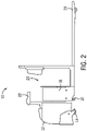
- Figs. 1 and 2 illustrate a non-limiting example of a material handling vehicle 10 according to the present disclosure.
- the material handling vehicle 10 may include a vehicle frame 12, a steerable traction wheel 14, a fixed axle 16, a power section 18, and an operator compartment 20.
- the power section 18 may be disposed within the vehicle frame 12 and may include a battery (or other power source) configured to supply power to various components of the material handling vehicle 10.
- a battery may supply power to a motor (not shown) and/or transmission (not shown) disposed within the power section 18 and configured to drive the traction wheel 14.
- the traction wheel 14 is arranged under the power section 18.
- a traction wheel(s) 14 may be arranged in another location under the vehicle frame 12.
- the operator compartment 20 may include a control handle 22 configured to provide a user interface for an operator and to allow the operator to control a speed and direction of travel of the material handling vehicle 10.
- the control handle 22 may be configured to manually steer and control power to the traction wheel 14.
- the material handling vehicle 10 includes a pair of forks 24 configured to engage loads (e.g., a pallet).
- the forks 24 can be raised and lowered by an actuator (not shown) to lift/place loads.
- forks can be coupled to a mast and be raised or lowered via actuators in response to commands from a control handle.
- the material handling vehicle 10 can be operated by an operator and can be capable of picking, placing, transporting, or otherwise manipulating a load, possibly including a pallet.
- the operator controls the material handling vehicle 10 so that the forks 24 engage a pallet carrying a load.
- the operator may extend or retract actuators (not shown) to pick, place, engage, or otherwise manipulate the load.
- the operator can move the load to another location as needed.
- a human operator may be replaced with an automated controller to comprise a fully-automated system (i.e., an autonomously guided material handling vehicle).
- Material handling vehicles can include systems for detecting objects in a path of travel. These systems can include scanners, which can have a defined field of view, and can scan for objects within the field of view.
- a preferred embodiment of a material handling vehicle 100 with an object detection system 110 is shown, the material handling vehicle 100 being generally similar to material handling vehicle 10.
- the object detection system 110 can include a mounting plate 112 and a scanner 114, which, in the illustrated embodiment, comprises a LiDAR scanner 114.
- the object detection system 110 can be positioned on a material handling vehicle in a way that is advantageous to sensing objects that may impede travel for the vehicle.
- the object detection system 110 is positioned on a lower portion 116 of a front side 118 of the material handling vehicle 100, the front side 118 being the side of the material handling vehicle 100 opposite a set of forks 120.
- a material handling vehicle may travel primarily in a "tractor first" direction, with a front side of a material handling vehicle generally facing in the direction of travel, and forks of the material handling vehicle extending in a direction opposite the direction of travel.
- the LiDAR scanner 114 being mounted on the front side 118, can scan an area in a direction of travel of the material handling vehicle. Being mounted on the lower portion 116, the LiDAR scanner 114 is advantageously positioned to detect objects or obstructions along a floor surface that could otherwise be undetected if the scanner 114 were mounted higher on the material handling vehicle 100.
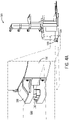
- the LiDAR scanner 114 may be housed within the lower portion 116, and the mounting plate 112 can provide a protective covering for the scanner 114. As illustrated in Fig. 3B , the mounting plate can define a cut-out portion 122, which can provide a window through which the scanner 114 can scan the environment of the material handling vehicle 100.
- the scanner 114 can have a maximum viewing angle A between a first boundary 126 and a second boundary 128, which can be dependent upon the internal placement of the scanner 114 in combination with the dimensions of the cut-out portion 122 and can further define a field of view 124. In some configurations, the viewing angle A can be up to about 110 degrees, or up to about 120 degrees, or up to about 130 degrees.
- the scanner field data can be combined and can be used in a travel control system (e.g., travel control system 200 shown in Fig. 5 ) for calculating an allowed or disallowed travel path for a material handling vehicle.
- a travel control system e.g., travel control system 200 shown in Fig. 5
- a scanner or LiDAR can be mounted on a material handling vehicle in other configurations, which can, for example, increase a field of view of the scanner.
- a material handling vehicle 100 can include a scanner assembly 130, which can be mounted on a lower portion 116 of the material handling vehicle 100, along a front face.
- the scanner assembly 130 can extend outwardly from the lower portion 116 by a distance D1.
- a scanner 132 can be mounted within the assembly 130, and can scan an area in front of, and on lateral sides of the scanner 132.
- the scanner 132 could have a viewing angle B which is larger than viewing angle A and defines a field of view 134 having a greater area than field of view 124.
- viewing angle B can be greater than 180 degrees.
- a field of view of an object detection sensor or scanner of the vehicle may change.
- this change can bring a previously undetected object into a path of the material handling vehicle, and, in some instances, absent system correction, the material handling vehicle may be travelling too quickly to avoid contact with the undetected object.
- an object detection system may require an amount of time to scan the new field of view for objects that may impede travel.
- systems can be provided for a material handling vehicle that can limit a speed of the material handling vehicle in response to a change in trajectory, to mitigate possible contact with previously undetected objects.
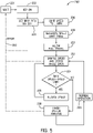
- Fig. 5 illustrates an exemplary embodiment of a travel control system 200 for a material handling vehicle (e.g., material handling vehicles 10, 100), which can be implemented by a control system 150 (e.g., as shown in Fig. 6 ) of the material handling vehicle 100.
- the travel control system 200 can calculate speed limits based on properties of a material handling vehicle and define potential and allowed travel paths of the material handling vehicle.
- the process can start at step 202, with a material handling vehicle being keyed on.
- one or a series of processes can be initiated to power operation of the material handling vehicle. For example, an engine of the material handling vehicle can be started, a start-up sequence for a control system can be initiated, etc.
- properties of a material handling vehicle can be obtained.
- Information obtained at step 204 can include physical properties of the material handling vehicle 100, and can be used to determine speed limits, allowed and disallowed paths of the material handling vehicle 100 for different dynamic conditions, such as a steer angle or range of steering angles.
- the information can include intrinsic aspects of the material handling vehicle 100, which can include vehicle weight, vehicle height, vehicle width, drive wheel location, and non-drive wheel locations, as non-limiting examples.
- This information can be received at a processor 152 of control system 150 of the material handling vehicle and used to calculate maximum speed limits for different conditions of operation of the material handling vehicle.
- Fig. 6 illustrates an exemplary communication system 300 for computing elements that can allow the control system 150 of the material handling vehicle 100 to obtain information about the material handling vehicle either from a memory 160 of the control system 150, or from a remote computing system 304.
- material handling vehicle 100 can include the control system 150, which can include a processor 152, a display 154, one or more inputs 156, one or more communication systems 158, and/or memory 160.
- the control system can also include the scanner 114, speed sensors 162, steer angle sensors 164, and a motor control unit 166.
- processor 152 can be any suitable hardware processor or combination of processors, such as a central processing unit (CPU), a graphics processing unit (GPU), an application specific integrated circuit (ASIC), a field-programmable gate array (FPGA), etc.
- display 154 can include any suitable display device, such as a computer monitor, a touchscreen, a television, etc.
- inputs 156 can include any suitable input devices and/or sensors that can be used to receive user input, such as a keyboard, a mouse, a touchscreen, a microphone, a camera, etc.
- communications systems 158 can include any suitable hardware, firmware, and/or software for communicating information over communication network 302 and/or any other suitable communication networks.
- communications systems 158 can include one or more transceivers, one or more communication chips and/or chip sets, etc.
- communications systems 158 can include hardware, firmware and/or software that can be used to establish a Wi-Fi connection, a Bluetooth connection, a cellular connection, an Ethernet connection, etc.
- memory 160 can include any suitable storage device or devices that can be used to store instructions, values, etc., that can be used, for example, by processor 152.
- Memory 160 can include any suitable volatile memory, non-volatile memory, storage, or any suitable combination thereof.
- memory 160 can include random access memory (RAM), read-only memory (ROM), electronically-erasable programmable read-only memory (EEPROM), one or more flash drives, one or more hard disks, one or more solid state drives, one or more optical drives, etc.
- RAM random access memory
- ROM read-only memory
- EEPROM electronically-erasable programmable read-only memory
- memory 260 can have encoded thereon a computer program for controlling operation of material handling vehicle 100, including by implementing all or part of the travel control system 200 illustrated in Fig. 5 .
- Information including intrinsic properties of the material handling vehicle 100 can be static, and can be stored in the memory 160 of the material handling vehicle, and can be provided to the processor 152 for calculation of speed limit tables.
- some information of the material handling vehicle 100 to be used in calculating speed limits can be dynamic information that can be obtained through sensors of the material handling vehicle.
- a weight sensor or sensors (not shown) can be provided for a material handling vehicle, or for a load of the material handling vehicle, and can be used to calculate a stopping distance of the material handling vehicle.
- sensing elements and control units of the material handling vehicle can be operatively included in the control system 150.
- a control system 150 can include steer angle sensors 164 for sensing a current steer angle of the vehicle, and the steer angle sensor 164 can produce a signal indicative of a steer angle which can be provided to the processor 152.
- the steer angle can be sensed through a sensor 164 at a steering element (e.g., control handle 22 of material handling vehicle 10).
- the sensor 164 can be any sensor known in the art for measuring a steering angle of a vehicle, which in some non-limiting examples can include gyroscopes or accelerometers.
- a steer angle can be calculated from an orientation of the material handling vehicle 100, which can be obtained through visual sensors, such as cameras, for example.
- Speed sensors 162 can also be provided for the material handling vehicle to sense a speed and communicate the speed to the processor 152.
- the speed sensor 162 can be any sensor known in the art for measuring a speed of a vehicle, including, but not limited to accelerometers or gyroscopes.
- a motor control unit 166 can be provided in the control system 150. The motor control unit 166 can be in communication with the processor 152 and can reduce a speed of a motor of the material handling vehicle 100 or set a limit on the speed of the material handling vehicle 100 based on a signal received from 152.
- the elements of the control system 150 can communicate using standardized communication protocols.
- the elements of a control system 150 can communicate over a controller area network ("CAN") bus 168, which can provide for communication between elements without the need for specific wired connections between each element in communication with other elements of the control system 250.
- CAN controller area network
- Messages can be provided from a given element to the CAN 168, which each of the other elements are connected to, and the messages can be of a format to be consumed by the element for which it is intended.
- signals between elements for example signals from the scanner 114 to the processor 152, or from the processor 152 to the motor control unit 166 can be contained in a message provided on the CAN bus 168.
- control system 150 can be operatively connected to computing device 304 through a communication network 302.
- the communications network 302 can be a local area network, a wide area network, etc.
- the computing device 304 can include processor 306, display 308, inputs 310, communication system 312, and memory 314 which can be similar to the corresponding components of control device 150.
- the memory 314 can include persistent memory which can store information about a material handling vehicle (e.g., material handling vehicle 100) or multiple material handling vehicles.
- the computing device 304 Upon a request (e.g., a request received at communication system 312), the computing device 304 can return the information to the control system 150 of material handling vehicle 100 for use in object detection systems of the material handling vehicle 100. This information can be provided to the processor 152 directly via the CAN bus 168. Additionally or alternatively, the information can be provided from the communication system 158 to the memory 160 through messages sent on the CAN bus 168.
- a speed of the material handling vehicle 100 can be temporarily restricted until the travel control system 200 can generate a speed limit table.
- the temporary speed limit can be 1 mile per hour, but other configurations are possible.
- a temporary speed limit for a material handling vehicle could be about 0 mph, or 2 mph, or 3 mph.
- the temporary speed limit could be set by a manager of a facility, for example, via the inputs 156 of the control system 150.
- the temporary speed limit could be hard-coded in memory 160, and can be included in the material handling vehicle information received at step 204.
- the travel control system 200 upon material handling vehicle startup, can generate a speed limit table of maximum speeds for the material handling vehicle 100 when the material handling vehicle 100 is steered at a given angle or within a given range of angles. These speed limits can be generated to minimize possible contact with objects that may not be in a field of view of a scanner of a material handling vehicle. For example, a speed that can be allowed in a first direction of travel can bring the material handling vehicle 100 into contact with an object outside of the field of view 124 if the speed is maintained when a material handling vehicle is steered toward a trajectory outside of the previous field of view 124.
- a non-limiting representative generated speed limit table is shown below. The steer angles shown are absolute values, and thus the associated speed limits would be applied to the corresponding negative steer angle.
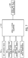
- Speed limits for a material handling vehicle can be generated for certain dynamic conditions of the material handling vehicle, including steer angle. Although limiting the speed of a material handling vehicle can increase vehicle path travel time, the speed limit can allow a scanner (e.g., scanner 114) enough time to react to an object during a steering maneuver. As illustrated in the input-output diagram of Fig. 7 , the travel control system 200 can implement an algorithm 350, which can receive inputs for a material handling vehicle dynamics model 352, a scanner location and field of view 354, a desired stop distance from an object 356, and desired steer angle breakpoints 358, and can output speed limits as a function of angle 360 (e.g., as shown in the representative generated speed limit table shown above).
- algorithm 350 can receive inputs for a material handling vehicle dynamics model 352, a scanner location and field of view 354, a desired stop distance from an object 356, and desired steer angle breakpoints 358, and can output speed limits as a function of angle 360 (e.g., as shown in the representative generated speed limit table shown above).
- the material handling vehicle dynamics model input at 352 can include the material handling information obtained at step 204 of the travel control system 200. For example, determining a speed limit for a given steering angle can require calculating a path of the vehicle, to determine a probability of a portion of the material handling vehicle contacting an object.
- a travel path can be represented as two concentric circles, representing two selected edges of the material handling vehicle.
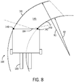
- Exemplary selected edges of steer drive material handling vehicle 100 are reflected in Fig. 7 at point 140 and point 142, which can be positioned on opposite lateral sides of material handling vehicle 100.
- the point 140 can travel along a circumference 141 of a circle having a radius R1 and point 142 can travel along circumference 143 of a concentric circle with a radius R2.
- the circumference 141 of the first circle and the circumference of the second circle 143 can define a projected path 146 of the material handling vehicle.
- Geometric properties of the concentric circle representing the travel path of respective points 140, 142 can be used in a calculation to determine the projected path 146 of the vehicle 100.
- the projected path can be used to calculate a speed limit of the material handling vehicle 100. For example, a speed limit can be determined to ensure that the projected path does not coincide or intersect with a disallowed travel path, based on other factors (e.g., a combination of the inputs 354, 356, 368).
- a speed limit for a given steering angle can be determined in part based on a stopping distance for a given trajectory.
- Fig. 9 illustrates a projected path 170 of material handling vehicle 100, which, as shown, is traveling at a rate of 4.7 mph with a steering angle of 13 degrees.
- Line 172 illustrates a stopping distance, which is the distance at which the material handling vehicle 100 could safely be stopped given an initial trajectory, position, and steering angle of the vehicle.
- a material handling vehicle having a greater weight may also have a greater stopping distance, as it can require more energy to slow, while a stopping distance of a vehicle having comparatively less weight would be shorter.
- the stopping distance 172 can factor into the calculation of a speed limit of a material handling vehicle for different steering angles, as reducing a speed of the material handling vehicle 100 can provide an object sensing system 110 time to adjust to scan the new direction of travel, while also ensuring that the vehicle 100 is not travelling at a rate that is likely to cause contact with a newly discovered object.
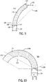
- Fig. 10 illustrates a projected travel path 170A of the material handling vehicle 100, which, as illustrated, includes an allowed portion 174, and a disallowed portion 176.
- the allowed portion 174 can be a portion of the path 170A that is within the combined scanner field of view 124 (e.g., between the first boundary 126 and the second boundary 128), which can be determined by a position of the scanner 114 on the vehicle, a configuration of the scanner (e.g., within the lower portion 116 of the material handling vehicle 100 illustrated in Figs.
- a speed limit for a given steer angle can be calculated to ensure that a projected stopping distance of the material handling vehicle 100 is within the allowed portion 174 and is not in the disallowed portion 176.
- the speed limit for a given steering angle can ensure that the vehicle 100 could be brought to a stop before contact with an object that was previously outside the scanner field of view 124.
- the algorithm 350 for determining a speed limit as a function of a steering angle 360 can also receive as input a desired stop distance from an object 356.
- a speed limit can be determined to ensure that a material handling vehicle can be stopped at a predetermined distance from an object that may fall outside a field of view of a scanner.
- a speed limit of material handling vehicle 100 travelling at a given steer angle can be determined to ensure that the material handling vehicle could stop at a buffer distance D2 from the boundary 128.
- the stopping distance of the material handling vehicle can be set to the distance to the boundary 128 for a given steer angle, minus distance D2, and a speed can be selected to achieve this stopping distance given buffer distance D2.
- the area outside the scanner's 114 field of view 124 may thus be presumed to include objects that may impede travel.
- the buffer distance D2 can be set as a default, while in other embodiments, this could be configured by a user (e.g., a manager of a facility).
- the buffer distance D2 can be measured as a minimum distance between a boundary of a field of view (e.g., boundaries 126, 128) and the point along the projected vehicle path 170 that is closest to the boundary 126, 128 that would intersect with the projected path 170 of the material handling vehicle 100.
- a speed limit calculated for speed in steer algorithm 350 can be calculated according to a series of equations that can use the inputs 352, 354, 356, 358.
- a first equation or set of equations representing the travel paths of points 140, 144 along the arcs of concentric circles can have a general form R ⁇ 2.
- the combined scanner view angle A can be constrained in a second equation or set equations, which can include one or more linear equations.
- Solving for the first equation and inserting the results into the second equation can produce a third equation, which is a quadratic equation. Aspects of the third equation can represent the intersect point of the travel path and scanner view angle (e.g., scanner view angles A and/or B).
- a fourth equation can represent a line drawn from the material handling vehicle reference location to the intersect point with a boundary (e.g., boundaries 126, 128), with the magnitude or length of the line representing the derived stopping distance for a given steer angle.
- the stopping distance e.g., a distance from the material handling vehicle 100 to stopping distance 172
- the fifth equation can represent a material handling vehicle speed limit for a given steer angle.
- desired steer angle breakpoints 358 can be included as input into the speed in steer algorithm 350.
- a speed limit for a material handling vehicle can be set for at least one steering angle range or a plurality of steering angle ranges, and the steer angle breakpoints can be boundaries of these ranges.
- steer angle breakpoint angles can be defined as 10 degrees, 20 degrees, 30 degrees, 40 degrees, and 50 degrees respectively, and can thus respectively define steering angle ranges of less than 10 degrees, 10-20 degrees, 30-40 degrees, 40-50 degrees, and greater than 50 degrees.
- a user could select different breakpoint angles, and could alternatively select more or fewer breakpoint angles.
- a first speed limit can be applied when the material handling vehicle 100 is steered within the 10-20 degree range (e.g., 5 mph), and a different speed limit (e.g., 4 mph) can be imposed when a steer angle of the material handling vehicle 100 has a steering angle within the 20-30 degree range.
- the breakpoint angles could be hard-coded as defaults into a travel control system of a material handling vehicle (e.g., in memory 160 of control system 150).
- a user can select desired breakpoint angles (e.g., using the inputs 156 or the inputs 310 shown in Fig. 6 ).
- the output of the speed in steer algorithm could thus be a table (e.g., the representative speed limit table shown above) which assigns speed limits to ranges of steering angles of a material handling vehicle, based on the inputs 352, 354, 356, and 358.
- the speed of the material handle 100 can be reduced or limited based on a communication from the processor 152 to the motor control unit 155 over the CAN bus 168, as shown in Fig. 6 .
- a speed limit table of a travel control system can include speed limits that are associated with specific maneuvers of a material handling vehicle, and these speed limits can be static, rather than being generated by an algorithm (e.g., algorithm 350).
- two frequent steering maneuvers include right angle turns (i.e., a 90 degree turn), and a pivot (e.g., a 180 degree), as illustrated in Fig. 11 .
- Right angle turns are commonly performed when turning into an aisle, turning out of an aisle, and turning around a corner.
- Pivots are commonly performed for a turnaround out of aisle, load drop off, and load engagement.
- a projected path 170B during a pivot maneuver can be tightly circumscribed.
- a cut-off angle can be defined for a pivot steer maneuver, which can allow the material handling vehicle 100 to proceed without a speed limit, or with a speed limit that is greater than what would be provided in the algorithm 350 when engaged in maneuvers such as a right angle turn or a pivot.
- a steer angle for a pivot or a right angle turn can be less than 180 degrees or 90 degrees respectively, and thus, a 90 degree turn of the material handling vehicle 100 could be accomplished by maintaining travel at another steer angle for a period of time, until the material handling vehicle 100 is oriented at a 90 degree angle relative to an initial position.
- a steer angle cutoff of 75 degrees can be incorporated to allow the material handling vehicle 100 to travel (i.e., pivot) at a higher maximum speed when the steer angle of the material handling vehicle 100 is above a predefined steer angle that constitutes pivot.
- the material handling vehicle 100 can travel at speeds up to 3 mph during a pivot operation, when the steer angle of the material handling vehicle 100 exceeds 75 degrees.
- the speed limit when the cut-off angle is detected, can be allowed to be higher than the speeds identified in the generated speed limit table.
- the pivot angle and associated speed limit can be included in the speed limit table.
- a cut-off pivot angle and an associated speed limit can be included in the material handling vehicle information provided at step 204 of vehicle travel control system 200.
- a cut-off pivot angle and an associated speed limit can be set by a user of the material handling vehicle.
- the travel control system 200 can allow full travel of material handling vehicle 100 at step 210, once the speed limit table has been generated at step 208.
- full travel can be allowed before a speed limit table is generated, or during a speed limit table generation.
- a material handling vehicle may not be allowed to travel until the speed limit table has been generated.
- Full travel allows the material handling vehicle 100 to operate without the temporary restrictions imposed at step 206, for example, and can permit operation of the material handling vehicle 100 in accordance with the speed limits generated at step 208.
- a speed and steer angle of material handling vehicle 100 can be sampled at a given time interval.
- the speed can be obtained from sensors of a material handling vehicle, which can include, for example, accelerometers, gyroscopes, or some other sensing devices known to those of ordinary skill in the art.
- the speed and steer angle of a material handling vehicle (e.g., material handling vehicle 100, 10) can be sampled or obtained at set time intervals.
- speed and steer angle can be sampled, once per millisecond, or once every 10 milliseconds, or once every 100 milliseconds, once every second, or once every 5 seconds, or once every 10 seconds.
- the speed and steer angle of a material handling vehicle can be sampled upon completion of steps 214, 216, 218, and 220.
- a polling or sampling interval can be configured by a user.
- the travel control process can evaluate whether the speed of the material handling vehicle 100, obtained at step 212, exceeds the speed limit generated at step 208 for the current steer angle of the material handling vehicle.
- a speed of the material handling vehicle can be reduced at step 216. Reducing the speed of the material handling vehicle can reduce the risk of contact with an object, as described above, and can also be beneficial in providing additional time for the scanner to adjust to the changed angle of the material handling vehicle 100, and scan for additional potential objects in the path of the material handling vehicle 100.
- the speed of the material handling vehicle 100 can be reduced by a predetermined increment (e.g., 0.1 mph) which can slow the material handling vehicle 100 without producing an unnecessarily uncomfortable change in acceleration, or deceleration.
- a predetermined increment e.g., 0.1 mph
- the travel control system 200 can bring the material handling vehicle 100 to the next speed set point (e.g., 4 mph) in predetermined increments, e.g., 0.1 mph, therefore expanding the viewing range of the object sensor system. If the operator continues to steer and increases the steer angle, the travel control system 200 can continue to adjust the material handling speed within the speed limit table ranges to maintain maximum viewing range.
- the vehicle travel control system 200 can again sample the speed and steer angle of the material handling vehicle 100, and evaluate if additional deceleration is required, or if the trajectory of the material handling vehicle is within the speed limits generated at step 208. In other embodiments, if a speed of the material handling vehicle exceeds a speed limit for the current steer angle, the vehicle can be decelerated by an amount necessary to bring the speed of the material handling vehicle beneath the speed limit before the speed and steer angle are sampled again.
- Normal operation can include unrestricted operation, for example, where the system is not reducing a speed of the material handling vehicle 100 or otherwise overriding operating parameters of the material handling vehicle 100.
- operation of the material handling vehicle 100 can be halted or paused if the system encounters an error 222 and a step cannot be completed.
- a step cannot be completed.
- the system 200 can impose a wait period at 224 before attempting to again resume the process and start the material handling vehicle 100 at step 202.
- the user of a material handling vehicle must wait a predetermined time before attempting to operate the material handling vehicle 100 again.
- the system can automatically perform a retry operation after a given time interval, which could be a system parameter than can be configured by a user, for example.
- Errors 222 can occur at other steps of the travel control system 200, including, for example, when sampling speed and steer angle data at step 212.
- an error may prompt other system responses. For example, when an error occurs, operation of the material handling vehicle can be permitted with a reduced speed limit for the vehicle (e.g., 1 mph).
Landscapes
- Engineering & Computer Science (AREA)
- Structural Engineering (AREA)
- Transportation (AREA)
- Physics & Mathematics (AREA)
- Automation & Control Theory (AREA)
- General Physics & Mathematics (AREA)
- Civil Engineering (AREA)
- Life Sciences & Earth Sciences (AREA)
- Geology (AREA)
- Mechanical Engineering (AREA)
- Remote Sensing (AREA)
- Radar, Positioning & Navigation (AREA)
- Aviation & Aerospace Engineering (AREA)
- Electromagnetism (AREA)
- Chemical & Material Sciences (AREA)
- Combustion & Propulsion (AREA)
- Optics & Photonics (AREA)
- Control Of Position, Course, Altitude, Or Attitude Of Moving Bodies (AREA)
- Steering Control In Accordance With Driving Conditions (AREA)
Applications Claiming Priority (1)
| Application Number | Priority Date | Filing Date | Title |
|---|---|---|---|
| US202163195125P | 2021-05-31 | 2021-05-31 |
Publications (4)
| Publication Number | Publication Date |
|---|---|
| EP4099126A2 true EP4099126A2 (fr) | 2022-12-07 |
| EP4099126A3 EP4099126A3 (fr) | 2023-05-03 |
| EP4099126C0 EP4099126C0 (fr) | 2026-01-21 |
| EP4099126B1 EP4099126B1 (fr) | 2026-01-21 |
Family
ID=81854354
Family Applications (1)
| Application Number | Title | Priority Date | Filing Date |
|---|---|---|---|
| EP22176368.3A Active EP4099126B1 (fr) | 2021-05-31 | 2022-05-31 | Systèmes et procédés de commande de déplacement de véhicule de manutention de matériaux basés sur la detection de la vitesse et de l'angle de braquage |
Country Status (6)
| Country | Link |
|---|---|
| US (1) | US12210350B2 (fr) |
| EP (1) | EP4099126B1 (fr) |
| CN (1) | CN115477253A (fr) |
| AU (1) | AU2022203598A1 (fr) |
| CA (1) | CA3161143A1 (fr) |
| MX (1) | MX2022006520A (fr) |
Families Citing this family (9)
| Publication number | Priority date | Publication date | Assignee | Title |
|---|---|---|---|---|
| DE102020110180A1 (de) * | 2020-04-14 | 2021-10-14 | Hubtex Maschinenbau Gmbh & Co. Kg | Flurförderzeug mit Lastaufnahmemitteln zur Aufnahme von Langgut |
| MX2022006733A (es) * | 2021-06-03 | 2022-12-05 | Raymond Corp | Comunicacion de vehiculo a vehiculo para conocimiento de trayectoria de un vehiculo de manejo de materiales. |
| DE102021121222A1 (de) * | 2021-08-16 | 2023-02-16 | Jungheinrich Aktiengesellschaft | Autonom geführtes Flurförderzeug mit einem Paar von Scanner-Einheiten |
| JP7468503B2 (ja) * | 2021-12-28 | 2024-04-16 | トヨタ自動車株式会社 | 搬送ロボット |
| GB2618546B (en) * | 2022-05-09 | 2024-09-04 | Jaguar Land Rover Ltd | Control system and method for vehicle steering |
| JP7669410B2 (ja) * | 2023-03-29 | 2025-04-28 | 三菱ロジスネクスト株式会社 | 荷役システムおよび無人搬送車 |
| EP4464643B1 (fr) * | 2023-05-16 | 2026-07-22 | Jungheinrich Aktiengesellschaft | Procédé de traitement d'obstacles dans un chariot de manutention |
| US20250058772A1 (en) * | 2023-08-20 | 2025-02-20 | Michael Don Harper | Collision avoidance system for mobility scooter |
| US20250370464A1 (en) * | 2024-05-31 | 2025-12-04 | Crown Equipment Corporation | Systems and methods for providing a zone in a covered environment |
Family Cites Families (12)
| Publication number | Priority date | Publication date | Assignee | Title |
|---|---|---|---|---|
| WO1991009375A1 (fr) | 1989-12-11 | 1991-06-27 | Caterpillar Inc. | Systeme, appareil et procede integres de calcul de position et de navigation pour vehicules |
| US8577551B2 (en) * | 2009-08-18 | 2013-11-05 | Crown Equipment Corporation | Steer control maneuvers for materials handling vehicles |
| JP6272347B2 (ja) | 2013-11-08 | 2018-01-31 | 株式会社日立製作所 | 自律走行車両、及び自律走行システム |
| US9989967B2 (en) | 2014-03-04 | 2018-06-05 | Cybernet Systems Corporation | All weather autonomously driven vehicles |
| EP3475214B1 (fr) | 2016-06-24 | 2020-06-10 | Crown Equipment Corporation | Badge électronique d'authentification et de suivi d'un utilisateur de véhicule industriel |
| EP4603939A3 (fr) | 2016-08-26 | 2026-01-14 | Crown Equipment Corporation | Outils de balayage d'obstacles de véhicule de manutention de matériaux |
| CA3035116C (fr) | 2016-08-26 | 2023-08-29 | Crown Equipment Corporation | Validation de trajet et modification de trajet dynamique de vehicule de manutention de materiaux |
| CA3043940A1 (fr) | 2016-12-22 | 2018-06-28 | Macdonald, Dettwiler And Associates Inc. | Procede et systeme d'aide discrete a la conduite pour un vehicule destines a eviter des dangers |
| CN110462544A (zh) | 2017-03-20 | 2019-11-15 | 御眼视觉技术有限公司 | 自主车辆的轨迹选择 |
| US11834058B2 (en) * | 2019-01-04 | 2023-12-05 | Toyota Research Institute, Inc. | Systems and methods for controlling a vehicle based on vehicle states and constraints of the vehicle |
| US11332132B2 (en) | 2019-08-30 | 2022-05-17 | Argo AI, LLC | Method of handling occlusions at intersections in operation of autonomous vehicle |
| US12162349B2 (en) * | 2021-02-01 | 2024-12-10 | Caterpillar Paving Products Inc. | Controlling machine operation including limiting machine speed |
-
2022
- 2022-05-27 AU AU2022203598A patent/AU2022203598A1/en active Pending
- 2022-05-30 MX MX2022006520A patent/MX2022006520A/es unknown
- 2022-05-31 CN CN202210611581.7A patent/CN115477253A/zh active Pending
- 2022-05-31 EP EP22176368.3A patent/EP4099126B1/fr active Active
- 2022-05-31 CA CA3161143A patent/CA3161143A1/fr active Pending
- 2022-05-31 US US17/828,806 patent/US12210350B2/en active Active
Also Published As
| Publication number | Publication date |
|---|---|
| US20220390955A1 (en) | 2022-12-08 |
| MX2022006520A (es) | 2022-12-13 |
| CN115477253A (zh) | 2022-12-16 |
| AU2022203598A1 (en) | 2022-12-15 |
| EP4099126C0 (fr) | 2026-01-21 |
| US12210350B2 (en) | 2025-01-28 |
| EP4099126B1 (fr) | 2026-01-21 |
| CA3161143A1 (fr) | 2022-11-30 |
| EP4099126A3 (fr) | 2023-05-03 |
Similar Documents
| Publication | Publication Date | Title |
|---|---|---|
| US12210350B2 (en) | Systems and methods for material handling vehicle travel control based on object detection systems | |
| EP4118507B1 (fr) | Procédé d'adaptation de trajet de véhicule autoconduit | |
| US11912303B2 (en) | Vehicle obstacle-avoidance method, apparatus and vehicle | |
| EP2685337A1 (fr) | Correction de direction pour un véhicule de manutention de matériaux commandé à distance | |
| CN103688226A (zh) | 用于自动校准车辆参数的方法和装置 | |
| EP2897017A2 (fr) | Manoeuvres de commande de braquage pour véhicules de manutention | |
| CN111533051A (zh) | 托盘位姿检测方法、装置、叉车和货运系统 | |
| EP4098600B1 (fr) | Communication de véhicule à véhicule pour la connaissance de la trajectoire d'un véhicule de manutention | |
| US20220073105A1 (en) | Traveling parameter optimization system and traveling parameter optimization method | |
| EP4194989B1 (fr) | Systèmes et procédés de guidage de véhicule de manutention de matériaux | |
| US20240231356A9 (en) | Operation Assistance for Autonomous Material Handling Vehicles | |
| CN115167422A (zh) | 无人叉车控制方法、装置、设备及存储介质 | |
| HK40085249A (en) | Systems and methods for material handling vehicle travel control based on object detection systems | |
| US20250236498A1 (en) | Safety field switching based on end effector conditions in vehicles | |
| JP7544628B2 (ja) | 荷役車両及び判定プログラム | |
| WO2023192333A1 (fr) | Identification automatisée d'obstructions potentielles dans une zone de chute ciblée | |
| JP7198614B2 (ja) | 搬送装置、搬送装置の制御方法およびプログラム | |
| US20260056550A1 (en) | Conveyance apparatus and conveyance control apparatus | |
| WO2025262656A1 (fr) | Véhicule autonome, système et procédé de commande d'un véhicule autonome | |
| JP2024094461A (ja) | 荷役車両、荷役車両の制御方法及び荷役車両の制御プログラム | |
| HK40085000A (en) | Vehicle-to-vehicle communication for trajectory awareness of a material handling vehicle |
Legal Events
| Date | Code | Title | Description |
|---|---|---|---|
| PUAI | Public reference made under article 153(3) epc to a published international application that has entered the european phase |
Free format text: ORIGINAL CODE: 0009012 |
|
| STAA | Information on the status of an ep patent application or granted ep patent |
Free format text: STATUS: THE APPLICATION HAS BEEN PUBLISHED |
|
| AK | Designated contracting states |
Kind code of ref document: A2 Designated state(s): AL AT BE BG CH CY CZ DE DK EE ES FI FR GB GR HR HU IE IS IT LI LT LU LV MC MK MT NL NO PL PT RO RS SE SI SK SM TR |
|
| PUAL | Search report despatched |
Free format text: ORIGINAL CODE: 0009013 |
|
| AK | Designated contracting states |
Kind code of ref document: A3 Designated state(s): AL AT BE BG CH CY CZ DE DK EE ES FI FR GB GR HR HU IE IS IT LI LT LU LV MC MK MT NL NO PL PT RO RS SE SI SK SM TR |
|
| RIC1 | Information provided on ipc code assigned before grant |
Ipc: G05D 1/02 20200101AFI20230328BHEP |
|
| STAA | Information on the status of an ep patent application or granted ep patent |
Free format text: STATUS: REQUEST FOR EXAMINATION WAS MADE |
|
| 17P | Request for examination filed |
Effective date: 20231031 |
|
| RBV | Designated contracting states (corrected) |
Designated state(s): AL AT BE BG CH CY CZ DE DK EE ES FI FR GB GR HR HU IE IS IT LI LT LU LV MC MK MT NL NO PL PT RO RS SE SI SK SM TR |
|
| STAA | Information on the status of an ep patent application or granted ep patent |
Free format text: STATUS: EXAMINATION IS IN PROGRESS |
|
| 17Q | First examination report despatched |
Effective date: 20240320 |
|
| REG | Reference to a national code |
Ref country code: DE Ref legal event code: R079 Free format text: PREVIOUS MAIN CLASS: G05D0001020000 Ipc: G05D0001000000 Ref document number: 602022028728 Country of ref document: DE |
|
| RIC1 | Information provided on ipc code assigned before grant |
Ipc: G05D 1/00 20060101AFI20241008BHEP |
|
| GRAP | Despatch of communication of intention to grant a patent |
Free format text: ORIGINAL CODE: EPIDOSNIGR1 |
|
| STAA | Information on the status of an ep patent application or granted ep patent |
Free format text: STATUS: GRANT OF PATENT IS INTENDED |
|
| INTG | Intention to grant announced |
Effective date: 20250812 |
|
| GRAS | Grant fee paid |
Free format text: ORIGINAL CODE: EPIDOSNIGR3 |
|
| GRAA | (expected) grant |
Free format text: ORIGINAL CODE: 0009210 |
|
| STAA | Information on the status of an ep patent application or granted ep patent |
Free format text: STATUS: THE PATENT HAS BEEN GRANTED |
|
| AK | Designated contracting states |
Kind code of ref document: B1 Designated state(s): AL AT BE BG CH CY CZ DE DK EE ES FI FR GB GR HR HU IE IS IT LI LT LU LV MC MK MT NL NO PL PT RO RS SE SI SK SM TR |
|
| REG | Reference to a national code |
Ref country code: CH Ref legal event code: F10 Free format text: ST27 STATUS EVENT CODE: U-0-0-F10-F00 (AS PROVIDED BY THE NATIONAL OFFICE) Effective date: 20260121 |
|
| REG | Reference to a national code |
Ref country code: DE Ref legal event code: R096 Ref document number: 602022028728 Country of ref document: DE |
|
| REG | Reference to a national code |
Ref country code: IE Ref legal event code: FG4D |
|
| U01 | Request for unitary effect filed |
Effective date: 20260211 |
|
| U07 | Unitary effect registered |
Designated state(s): AT BE BG DE DK EE FI FR IT LT LU LV MT NL PT RO SE SI Effective date: 20260217 |
|
| U20 | Renewal fee for the european patent with unitary effect paid |
Year of fee payment: 5 Effective date: 20260420 |
|
| PG25 | Lapsed in a contracting state [announced via postgrant information from national office to epo] |
Ref country code: RS Free format text: LAPSE BECAUSE OF FAILURE TO SUBMIT A TRANSLATION OF THE DESCRIPTION OR TO PAY THE FEE WITHIN THE PRESCRIBED TIME-LIMIT Effective date: 20260421 |
|
| PG25 | Lapsed in a contracting state [announced via postgrant information from national office to epo] |
Ref country code: ES Free format text: LAPSE BECAUSE OF FAILURE TO SUBMIT A TRANSLATION OF THE DESCRIPTION OR TO PAY THE FEE WITHIN THE PRESCRIBED TIME-LIMIT Effective date: 20260121 |
|
| PG25 | Lapsed in a contracting state [announced via postgrant information from national office to epo] |
Ref country code: PL Free format text: LAPSE BECAUSE OF FAILURE TO SUBMIT A TRANSLATION OF THE DESCRIPTION OR TO PAY THE FEE WITHIN THE PRESCRIBED TIME-LIMIT Effective date: 20260121 |
|
| PGFP | Annual fee paid to national office [announced via postgrant information from national office to epo] |
Ref country code: GB Payment date: 20260420 Year of fee payment: 5 |
|
| PG25 | Lapsed in a contracting state [announced via postgrant information from national office to epo] |
Ref country code: GR Free format text: LAPSE BECAUSE OF FAILURE TO SUBMIT A TRANSLATION OF THE DESCRIPTION OR TO PAY THE FEE WITHIN THE PRESCRIBED TIME-LIMIT Effective date: 20260422 |
|
| PG25 | Lapsed in a contracting state [announced via postgrant information from national office to epo] |
Ref country code: NO Free format text: LAPSE BECAUSE OF FAILURE TO SUBMIT A TRANSLATION OF THE DESCRIPTION OR TO PAY THE FEE WITHIN THE PRESCRIBED TIME-LIMIT Effective date: 20260421 |
|
| PG25 | Lapsed in a contracting state [announced via postgrant information from national office to epo] |
Ref country code: HR Free format text: LAPSE BECAUSE OF FAILURE TO SUBMIT A TRANSLATION OF THE DESCRIPTION OR TO PAY THE FEE WITHIN THE PRESCRIBED TIME-LIMIT Effective date: 20260121 |
|
| PG25 | Lapsed in a contracting state [announced via postgrant information from national office to epo] |
Ref country code: IS Free format text: LAPSE BECAUSE OF FAILURE TO SUBMIT A TRANSLATION OF THE DESCRIPTION OR TO PAY THE FEE WITHIN THE PRESCRIBED TIME-LIMIT Effective date: 20260521 |