EP4099461B1 - Élément de batterie, batterie, dispositif électrique, et procédé et appareil de fabrication d'élément de batterie - Google Patents
Élément de batterie, batterie, dispositif électrique, et procédé et appareil de fabrication d'élément de batterie Download PDFInfo
- Publication number
- EP4099461B1 EP4099461B1 EP21827368.8A EP21827368A EP4099461B1 EP 4099461 B1 EP4099461 B1 EP 4099461B1 EP 21827368 A EP21827368 A EP 21827368A EP 4099461 B1 EP4099461 B1 EP 4099461B1
- Authority
- EP
- European Patent Office
- Prior art keywords
- electrode assembly
- electrode sheet
- electrode
- battery cell
- projection
- Prior art date
- Legal status (The legal status is an assumption and is not a legal conclusion. Google has not performed a legal analysis and makes no representation as to the accuracy of the status listed.)
- Active
Links
Images


Classifications
-
- H—ELECTRICITY
- H01—ELECTRIC ELEMENTS
- H01M—PROCESSES OR MEANS, e.g. BATTERIES, FOR THE DIRECT CONVERSION OF CHEMICAL ENERGY INTO ELECTRICAL ENERGY
- H01M10/00—Secondary cells; Manufacture thereof
- H01M10/05—Accumulators with non-aqueous electrolyte
- H01M10/058—Construction or manufacture
- H01M10/0587—Construction or manufacture of accumulators having only wound construction elements, i.e. wound positive electrodes, wound negative electrodes and wound separators
-
- H—ELECTRICITY
- H01—ELECTRIC ELEMENTS
- H01M—PROCESSES OR MEANS, e.g. BATTERIES, FOR THE DIRECT CONVERSION OF CHEMICAL ENERGY INTO ELECTRICAL ENERGY
- H01M10/00—Secondary cells; Manufacture thereof
- H01M10/04—Construction or manufacture in general
- H01M10/0431—Cells with wound or folded electrodes
-
- H—ELECTRICITY
- H01—ELECTRIC ELEMENTS
- H01M—PROCESSES OR MEANS, e.g. BATTERIES, FOR THE DIRECT CONVERSION OF CHEMICAL ENERGY INTO ELECTRICAL ENERGY
- H01M10/00—Secondary cells; Manufacture thereof
- H01M10/04—Construction or manufacture in general
- H01M10/0468—Compression means for stacks of electrodes and separators
-
- H—ELECTRICITY
- H01—ELECTRIC ELEMENTS
- H01M—PROCESSES OR MEANS, e.g. BATTERIES, FOR THE DIRECT CONVERSION OF CHEMICAL ENERGY INTO ELECTRICAL ENERGY
- H01M10/00—Secondary cells; Manufacture thereof
- H01M10/05—Accumulators with non-aqueous electrolyte
- H01M10/052—Li-accumulators
- H01M10/0525—Rocking-chair batteries, i.e. batteries with lithium insertion or intercalation in both electrodes; Lithium-ion batteries
-
- H—ELECTRICITY
- H01—ELECTRIC ELEMENTS
- H01M—PROCESSES OR MEANS, e.g. BATTERIES, FOR THE DIRECT CONVERSION OF CHEMICAL ENERGY INTO ELECTRICAL ENERGY
- H01M50/00—Constructional details or processes of manufacture of the non-active parts of electrochemical cells other than fuel cells, e.g. hybrid cells
- H01M50/10—Primary casings; Jackets or wrappings
- H01M50/102—Primary casings; Jackets or wrappings characterised by their shape or physical structure
- H01M50/107—Primary casings; Jackets or wrappings characterised by their shape or physical structure having curved cross-section, e.g. round or elliptic
-
- H—ELECTRICITY
- H01—ELECTRIC ELEMENTS
- H01M—PROCESSES OR MEANS, e.g. BATTERIES, FOR THE DIRECT CONVERSION OF CHEMICAL ENERGY INTO ELECTRICAL ENERGY
- H01M50/00—Constructional details or processes of manufacture of the non-active parts of electrochemical cells other than fuel cells, e.g. hybrid cells
- H01M50/40—Separators; Membranes; Diaphragms; Spacing elements inside cells
- H01M50/471—Spacing elements inside cells other than separators, membranes or diaphragms; Manufacturing processes thereof
- H01M50/474—Spacing elements inside cells other than separators, membranes or diaphragms; Manufacturing processes thereof characterised by their position inside the cells
-
- H—ELECTRICITY
- H01—ELECTRIC ELEMENTS
- H01M—PROCESSES OR MEANS, e.g. BATTERIES, FOR THE DIRECT CONVERSION OF CHEMICAL ENERGY INTO ELECTRICAL ENERGY
- H01M50/00—Constructional details or processes of manufacture of the non-active parts of electrochemical cells other than fuel cells, e.g. hybrid cells
- H01M50/40—Separators; Membranes; Diaphragms; Spacing elements inside cells
- H01M50/471—Spacing elements inside cells other than separators, membranes or diaphragms; Manufacturing processes thereof
- H01M50/477—Spacing elements inside cells other than separators, membranes or diaphragms; Manufacturing processes thereof characterised by their shape
-
- H—ELECTRICITY
- H01—ELECTRIC ELEMENTS
- H01M—PROCESSES OR MEANS, e.g. BATTERIES, FOR THE DIRECT CONVERSION OF CHEMICAL ENERGY INTO ELECTRICAL ENERGY
- H01M10/00—Secondary cells; Manufacture thereof
- H01M10/04—Construction or manufacture in general
- H01M10/0404—Machines for assembling batteries
- H01M10/0409—Machines for assembling batteries for cells with wound electrodes
-
- H—ELECTRICITY
- H01—ELECTRIC ELEMENTS
- H01M—PROCESSES OR MEANS, e.g. BATTERIES, FOR THE DIRECT CONVERSION OF CHEMICAL ENERGY INTO ELECTRICAL ENERGY
- H01M10/00—Secondary cells; Manufacture thereof
- H01M10/04—Construction or manufacture in general
- H01M10/049—Processes for forming or storing electrodes in the battery container
-
- H—ELECTRICITY
- H01—ELECTRIC ELEMENTS
- H01M—PROCESSES OR MEANS, e.g. BATTERIES, FOR THE DIRECT CONVERSION OF CHEMICAL ENERGY INTO ELECTRICAL ENERGY
- H01M2220/00—Batteries for particular applications
- H01M2220/20—Batteries in motive systems, e.g. vehicle, ship, plane
-
- Y—GENERAL TAGGING OF NEW TECHNOLOGICAL DEVELOPMENTS; GENERAL TAGGING OF CROSS-SECTIONAL TECHNOLOGIES SPANNING OVER SEVERAL SECTIONS OF THE IPC; TECHNICAL SUBJECTS COVERED BY FORMER USPC CROSS-REFERENCE ART COLLECTIONS [XRACs] AND DIGESTS
- Y02—TECHNOLOGIES OR APPLICATIONS FOR MITIGATION OR ADAPTATION AGAINST CLIMATE CHANGE
- Y02E—REDUCTION OF GREENHOUSE GAS [GHG] EMISSIONS, RELATED TO ENERGY GENERATION, TRANSMISSION OR DISTRIBUTION
- Y02E60/00—Enabling technologies; Technologies with a potential or indirect contribution to GHG emissions mitigation
- Y02E60/10—Energy storage using batteries
-
- Y—GENERAL TAGGING OF NEW TECHNOLOGICAL DEVELOPMENTS; GENERAL TAGGING OF CROSS-SECTIONAL TECHNOLOGIES SPANNING OVER SEVERAL SECTIONS OF THE IPC; TECHNICAL SUBJECTS COVERED BY FORMER USPC CROSS-REFERENCE ART COLLECTIONS [XRACs] AND DIGESTS
- Y02—TECHNOLOGIES OR APPLICATIONS FOR MITIGATION OR ADAPTATION AGAINST CLIMATE CHANGE
- Y02P—CLIMATE CHANGE MITIGATION TECHNOLOGIES IN THE PRODUCTION OR PROCESSING OF GOODS
- Y02P70/00—Climate change mitigation technologies in the production process for final industrial or consumer products
- Y02P70/50—Manufacturing or production processes characterised by the final manufactured product
Definitions
- a shape of any cross section of the electrode assembly perpendicular to the height direction of the battery cell is the polygon.
- any cross section of the prism in a direction perpendicular to its own height (that is, perpendicular to the height direction of the battery cell) is the same. Compared with the case where a shape of part of the cross section is different, the electrode assembly with the three-dimensional shape of prism is more convenient to be produced and manufactured.
- a vertex position of the polygon abuts against the inner wall of the housing.
- the vertex forms a fillet structure to increase a force bearing area and reduce the local stress of the vertex position, so as to further prevent excessive stress caused by excessive compression at the vertex, thereby preventing the performance degradation of the battery from affecting the cycle life of the battery cell.
- a ratio of a diameter of a circumscribed circle of the projection of the electrode assembly to a diameter of the accommodating cavity is 90%- ⁇ 100%.
- a ratio of a diameter of the circumscribed circle of the polygon formed by the projection of the electrode assembly to the diameter of the accommodating cavity is a group margin of the battery cell.
- the group margin is configured to be 90%-100%, in the case that the remaining space is provided for expansion of the electrode assembly, the battery cell has larger energy density, and it is also convenient to accommodate the electrode assembly.
- a performance of the battery cell may deteriorate or sharply drop.
- the inventor researched and found that a main reason for performance being worse of the battery cell is that an infiltrating effect of the electrolytic solution on the electrode sheet is worse after the battery cell is used for a period of time. And the worse the infiltrating effect of the electrolytic solution on the electrode sheet, the greater the performance attenuation of the battery, which seriously affects a cycle life of the battery.
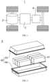
- the battery 4 may include the plurality of battery cells 45; the battery 4 may further include a box body 42 (or called a covering).
- the inner portion of the box body 42 is a hollow structure, and the plurality of battery cells 45 are accommodated in the box body 42.
- the box body 42 may include two parts, which are referred to herein as a first part 43 and a second part 44, respectively, and the first part 43 and the second part 44 are buckled together.
- the shapes of the first part 43 and the second part 44 may be determined according to the shape of the combined plurality of battery cells 45, and the first part 43 and the second part 44 may each have an opening.
- the battery cell 45 further includes one or more electrode terminals 210, and the electrode terminal 210 is arranged on the end cover assembly 200.
- the electrode terminal 210 is connected with a connecting member, or may also be called an adapter (not shown in the figure), which is located between the end cover assembly 200 and the electrode assembly 300 and is used to electrically connect the electrode assembly 300 and the electrode terminal 210.
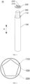
- the accommodating cavity 110 is configured to be cylindrical.
- a regular pentagon is taken as an example to show a schematic diagram of a projection of the battery cell 45 along a height direction of the battery cell, where it shows a projection of the electrode assembly 300 and a projection of the accommodating cavity 110.
- the projection of the accommodating cavity 110 along the height direction of the battery cell are a circle, and the projection of the electrode assembly 300 along the height direction of the battery cell is a polygon.
- the electrode assembly 300 Since the electrode assembly 300 is not prone to the local stress concentration, and there is still a remaining space between the electrode assembly 300 and the inner wall of the housing 100 to release the internal stress, which can not only prevent micro damages of the reduced porosity and rupture of the material particles due to the excessive compression of the electrode sheet of the electrode assembly 300, but also make the electrode sheet less prone to macro damages of breakage and fracture due to the excessive internal stress.
- an area of a regular polygon is greater than an area of a non-regular polygon with the same number of edges, which increases the energy density of the battery cell.
- FIG. 15 shows a projection of the first electrode 310 and the second electrode sheet 320.
- the first electrode sheet 310 is a positive electrode sheet
- the second electrode sheet 320 is a negative electrode sheet.
- the first electrode sheet 310 starts from one of the six areas and winds in a clockwise or counterclockwise direction
- the second electrode sheet 320 starts from one of the six areas and winds in the clockwise or counterclockwise direction.
- the first electrode sheet 310 and the second electrode sheet 320 are first stacked then wound, and the first electrode sheet 310 and the second electrode sheet 320 have the same winding direction.
- the number of layers of the electrode sheet in a certain area refers to a sum of the number of layers of the first electrode sheet 310 in said area and the number of layers of the second electrode sheet 320 in said area.
- the first electrode sheet 310 reaches or passes through one area, one layer of the first electrode sheet 310 is stacked in said area, and the number of layers of the first electrode sheet 310 is increased by one; similarly, each time the second electrode sheet 320 reaches or passes through one area, one layer of the second electrode sheet 320 is stacked in said area, and the number of layers of the second electrode sheet 320 is increased by one.
- an edge of the first electrode sheet's winding closing end 312 is not on any first straight line, and an edge of the second electrode sheet's winding closing end 322 is not on any first straight line.
- FIG. 19 shows a projection of the first electrode sheet 310 and the second electrode sheet 320, and an edge of the first electrode sheet's winding closing end 312 and an edge of the second electrode sheet's winding closing end 322 are both in the area VI, but not on the first straight line AO.
- a distance between a vertex A and the inner wall of the housing 100 is relatively reduced, so that the diameter of the circumscribed circle Ci is relatively reduced, which is equivalent to improving the energy density without increasing the group margin, and further taking into account the purposes of facilitating assembly and improving the energy density.
- an end face of the winding initial end may abut on a surface of the electrode sheet in an adjacent area, which causes the end face of the winding initial end to be easily rubbed, resulting in powder loss of a coating layer near the end surface, or resulting in the powder loss of the surface of the electrode sheet abutted by the end face.
- FIG. 19 a spacing between the electrode sheets is enlarged for ease of viewing, the actual dimension of the spacing between the electrode sheets is very small.
- an end face of the winding initial end of the first electrode sheet 310 may contact with a surface of the second electrode sheet 320 of an innermost layer in the area VI, and an end face of the first electrode sheet's winding initial end 311 is easy to be rubbed, resulting in powder loss of the coating layer near a contact part; similarly, assuming that an edge of the winding initial end of the second electrode sheet 320 is on the first straight line AO, an end face of the winding initial end of the electrode sheet 320 may contact with the surface of the second electrode sheet 320 of the innermost layer in the area VI, and an end face of the second electrode sheet's winding initial end 321 is easy to be rubbed, resulting in powder loss of the coating layer near the contact part
- an edge of the first electrode sheet's winding initial end 311, an edge of the second electrode sheet's winding initial end 321, an edge of the first electrode sheet's winding closing end 312, and an edge of the second electrode sheet's winding closing end 322 are not on the same diameter of the circumscribed circle Ci to avoid a local stress concentration due to step overlapping at local positions, and at the same time to avoid the thickness at the overlapping positions of steps being larger than other parts, so as to better use internal space and improve the internal space utilization to improve the energy density.
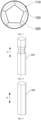
- the electrode assembly 300 is provided with a reel.
- the reel mentioned here refers to a polygonal cylinder arranged on an axis of the electrode assembly 300 to facilitate winding and forming of the electrode assembly 300.
- a number of edges or sides of the polygonal cylinder is the same as the number of edges of the set polygon, and the first electrode sheet 310 and the second electrode sheet 320 are wound around the reel to form the electrode assembly 300 with the same projected shape as the size of the set polygon.
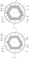
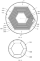
- FIG. 20 takes a regular hexagon as an example to show a schematic diagram of a projection when the electrode assembly 300 expands.
- a dotted line in FIG. 12 is a projection of the expanded electrode assembly 300, and in FIG. 20 , there is a non-smooth transition at the vertex A, and there are smooth transitions at the vertex B, the vertex C, the vertex D, the vertex E and the vertex F.
- the arc face formed at a smooth transition position basically completely contacts with the inner wall of the cylindrical housing 100, in other words, the contact area at the vertex B, the vertex C, the vertex D, the vertex E, and the vertex F is larger than that at the vertex A. Therefore, a force bearing area at the vertex of the smooth transition increases while an internal force per unit area decreases, that is, the stress is reduced, which alleviates the problem of the local stress concentration, further prevents the excessive compression of the electrode sheet, and alleviates the performance degradation of the battery cell caused by the excessive compression of the electrode sheet, thereby improving the cycle life of the battery cell.
- the electrode assembly 300 may not be a perfect regular polygon.
- An apex angle of the polygon can have a manufacturing tolerance of ⁇ 10%, and when the apex angle forms the fillet: 0.9*(180°-360°/n) ⁇ 1.10*(180°-360°/n), where ⁇ is an angle between extension lines of the two adjacent edges of the polygon, n is the number of edges of the polygon.
- an electronic insulating layer is also arranged between the first electrode sheet 310 and the second electrode sheet 320, and the electronic insulating layer may be a membrane.
- the second electrode sheet 320 is at the innermost layer, and at least the second membrane 340 covers the innermost layer.
- An inner side of the first electrode sheet 310 and an outer side of the second electrode sheet 320 are separated by the first membrane 330, and an outer side of the first electrode sheet 310 and an inner side of the second electrode sheet 320 are separated by the second membrane 340
- the first membrane 330 and the second membrane 340 continues to be wound to cover the first electrode sheet's winding closing end 312 and the second electrode sheet's winding closing end 322.
- the more turns the membrane is wound around the outer circumference of the electrode assembly 300 the better the binding performance to the electrode assembly 300 to prevent an internal resistance increase due to the loose of the electrode sheet, thereby avoiding the performance degradation of the battery caused by an internal resistance increase, so as to ensure the cycle life of the battery.
- at least one of the first membrane 330 and the second membrane 340 continues to be wound 0.25-5 turns after covering the first electrode sheet's winding closing end 312 and the second electrode sheet's winding closing end 322.
- the excessive number of winding turns of the membrane may occupy space between the electrode assembly 300 and the inner wall of the housing 100, in order to take into account both a wrapping effect and a space occupation problem, in some embodiments, at least one of the first membrane 330 and the second membrane 340 continues to be wound 1.25-2 turns after covering the first electrode sheet's winding closing end 312 and the second electrode sheet's winding closing end 322.
- FIG. 22 shows a view of a projection of the electrode assembly 300, and a binding layer 400 is arranged on the outside of the wound electrode assembly 300.
- the binding layer 400 is used to wrap the electrode assembly 300 to prevent the first electrode sheet 310 and the second electrode sheet 320 from loosening, and to prevent deformation due to the loose, so that the electrode assembly 300 maintains its set polygonal shape.
- the binding layer 400 has elasticity to allow the electrode assembly 300 to expand, that is, as the electrode assembly 300 expands outward, the binding layer 400 expands outward simultaneously, which prevents the electrode sheet from being over extruded by the binding layer 400 while preventing the electrode sheet from loosening.
- a thickness of the binding layer 400 is enlarged, which is only an illustration and does not represent an actual thickness of the binding layer 400, nor does it represent a size ratio of a projection of the binding layer 400 to the projection of the electrode assembly 300.
- the binding layer 400 possessing elasticity may be made of materials such as condensation polymer of terephthalic acid and ethylene glycol, or be made of pressure-sensitive adhesive, and a selection range of adhesive strength of the pressure-sensitive adhesive is being larger than 0.1 N/mm.
- the binding layer 400 is a sleeve, and the sleeve is sleeved on the outside of the electrode assembly 300.
- FIG. 23 shows a projection view of the electrode assembly 300, and a three-dimensional shape formed by the binding layer 400 after being sleeved on the outside of the electrode assembly 300 is the same as the three-dimensional shape of the electrode assembly 300.
- the three-dimensional shape of the binding layer 400 when it is not sleeved on the outside of the electrode assembly 300 is different from the three-dimensional shape of the electrode assembly 300. Due to its elasticity, the three-dimensional shape formed by the binding layer 400 after being sleeved on the outside of the electrode assembly 300 is the same as the three-dimensional shape of the electrode assembly 300.
- the three-dimensional shape of the binding layer 400 when it is not sleeved on the outside of the electrode assembly 300 is the same as the three-dimensional shape of the electrode assembly 300.
- FIG. 24 shows an exploded view of the battery cell 45, where the electrode assembly 300 is a regular hexagonal prism, and the binding layer 400 is a regular hexagonal prism.
- the binding layer 400 is of the same other three-dimensional shapes.
- an outer shape of the housing 100 is configured to be cylindrical, and correspondingly, a projection of an end cover assembly 200 along the height direction H of the battery cell is a circle.
- a projection of the outer shape of the end cover assembly 200 along the height direction H of the battery cell is a polygon
- at least an edge of the housing 100 at the opening is also the same polygon.
- the housing 100 and the end cover assembly 200 need to be aligned when assembling, so that vertexes and edges of the projections of the two can overlap; the housing 100 and the end cover assembly 200 need to be welded and fixed after the alignment, and when welding, it is necessary to stop the welding gun and change a welding direction at each vertex of the polygon.
- the cylindrical housing 100 and the end cover assembly 200 with a circular projection do not need to be aligned when assembling and can be directly covered. It can be welded along a circular path at one time without a pause when welding, which reduces difficulty of assembly, improves efficiency of assembly and reduces man-hour costs.
- the battery cell 45 and the battery 4 of the embodiments of the present application are described above, and the power consumption device is described by taking the vehicle 1 as an example.
- a method and an apparatus for producing a battery cell 45 according to the embodiments of the present application will be described below. For the parts that are not described in detail, reference is made to the foregoing embodiments.
- FIG. 25 shows a schematic flowchart of a method for producing a battery cell 45 according to an embodiment of the present application, and the method can include:
- FIG. 26 shows a schematic block diagram of an apparatus 500 for producing a battery cell 45 according to an embodiment of the present application
- the preparing apparatus 500 can include: a first providing apparatus 510, a second providing apparatus 520, and an assembling apparatus 530.
- a first providing apparatus 510 is used to provide a housing 100, and the housing 100 has a cylindrical accommodating cavity 110;
- a second providing apparatus 520 is used to provide an electrode assembly 300, and a projection of the electrode assembly 300 along a height direction H of the battery cell is a polygon;
- An assembling apparatus 530 is used to arrange the electrode assembly 300 in the accommodating cavity 110.
Landscapes
- Chemical & Material Sciences (AREA)
- Chemical Kinetics & Catalysis (AREA)
- Electrochemistry (AREA)
- General Chemical & Material Sciences (AREA)
- Engineering & Computer Science (AREA)
- Manufacturing & Machinery (AREA)
- Materials Engineering (AREA)
- Secondary Cells (AREA)
Claims (15)
- Élément de batterie (45), comprenant :un boîtier (100), avec une cavité de réception (110) cylindrique ;un ensemble électrode (300), agencé dans la cavité de réception (110), une protubérance de l'ensemble électrode (300) dans le sens d'une hauteur (H) de l'élément de batterie (45) étant un polygone, un espace restant étant situé entre l'ensemble électrode (300) et une paroi intérieure du boîtier (100) pour permettre à l'ensemble électrode (300) de se dilater ;l'élément de batterie étant caractérisé par :
une couche de liaison (400), configurée pour envelopper l'ensemble électrode (300), la couche de liaison (400) étant élastique pour permettre à l'ensemble électrode (300) de se dilater, un intervalle étant prévu entre la couche de liaison (400) et une paroi intérieure du boîtier (100). - Élément de batterie (45) selon la revendication 1, dans lequel une forme d'une quelconque section transversale de l'ensemble électrode (300) perpendiculaire au sens de la hauteur (H) de l'élément de batterie (45) est un polygone.
- Élément de batterie (45) selon l'une quelconque des revendications 1 et 2, dans lequel une forme tridimensionnelle de l'ensemble électrode (300) est un prisme ou un prisme régulier.
- Élément de batterie (45) selon l'une quelconque des revendications 1 à 3, dans lequel deux bords adjacents de la protubérance de l'ensemble électrode (300) possèdent une transition progressive pour faire du sommet du polygone un congé.
- Élément de batterie (45) selon l'une quelconque des revendications 1 à 4, dans lequel un rapport entre un diamètre d'un cercle circonscrit de la protubérance de l'ensemble électrode (300) et un diamètre de la cavité de réception (110) est compris entre 90 % et <100 %.
- Élément de batterie (45) selon l'une quelconque des revendications 1 à 5, dans lequel l'ensemble électrode (300) comprend une première feuille d'électrode (310) et une seconde feuille d'électrode (320) dont la polarité électrique est opposée à celle de la première feuille d'électrode (310), la première feuille d'électrode (310) et la seconde feuille d'électrode (320) étant enroulées pour former l'ensemble électrode (300) ; et
dans lequel une ligne de jonction entre un sommet quelconque de la protubérance de l'ensemble électrode (300) et un centre du cercle circonscrit de la protubérance de l'ensemble électrode (300) est définie comme une première ligne droite, une protubérance d'un bord de l'extrémité finale d'enroulement (312) de la première feuille d'électrode dans le sens de la hauteur (H) de l'élément de batterie (45) n'étant pas sur une quelconque première ligne droite, et une protubérance d'un bord de l'extrémité finale d'enroulement de la seconde feuille d'électrode (322) dans le sens de la hauteur (H) de l'élément de batterie (45) n'étant pas sur une quelconque première ligne droite. - Élément de batterie (45) selon l'une quelconque des revendications 1 à 6, dans lequel l'ensemble électrode (300) comprend une première feuille d'électrode (310) et une seconde feuille d'électrode (320) dont la polarité électrique est opposée à celle de la première feuille d'électrode (310), la première feuille d'électrode (310) et la seconde feuille d'électrode (320) étant enroulées pour former l'ensemble électrode (300) ; et
dans lequel une ligne de jonction entre un sommet quelconque de la protubérance de l'ensemble électrode (300) et un centre du cercle circonscrit de la protubérance de l'ensemble électrode (300) est définie comme une première ligne droite, une protubérance d'un bord de l'extrémité initiale d'enroulement (311) de la première feuille d'électrode dans le sens de la hauteur (H) de l'élément de batterie (45) n'étant pas sur une quelconque première ligne droite, et une protubérance d'un bord de l'extrémité initiale d'enroulement de la seconde feuille d'électrode (321) dans le sens de la hauteur (H) de l'élément de batterie (45) n'étant pas sur une quelconque première ligne droite. - Élément de batterie (45) selon l'une quelconque des revendications 1 à 7, dans lequel l'ensemble électrode (300) comprend une première feuille d'électrode (310) et une seconde feuille d'électrode (320) dont la polarité électrique est opposée à celle de la première feuille d'électrode (310), la première feuille d'électrode (310) et la seconde feuille d'électrode (320) étant enroulées pour former l'ensemble électrode (300) ; et
dans lequel une ligne de jonction entre un sommet quelconque de la protubérance de l'ensemble électrode (300) et un centre du cercle circonscrit de la protubérance de l'ensemble électrode (300) est définie comme une première ligne droite, la protubérance de l'ensemble électrode (300) étant divisée en une pluralité de régions par une pluralité de premières lignes droites, et une différence entre un nombre de couches de la feuille d'électrode dans deux régions quelconques étant inférieure ou égale à 1. - Élément de batterie (45) selon la revendication 8, dans lequel la protubérance d'un bord de l'extrémité initiale d'enroulement (311) de la première feuille d'électrode dans le sens de la hauteur (H) de l'élément de batterie (45) et la protubérance d'un bord de l'extrémité finale d'enroulement (312) de la première feuille d'électrode dans le sens de la hauteur (H) de l'élément de batterie (45) sont situées dans deux régions adjacentes, et la protubérance d'un bord de l'extrémité initiale d'enroulement (321) de la seconde feuille d'électrode dans le sens de la hauteur (H) de l'élément de batterie (45) et la protubérance d'un bord de l'extrémité finale d'enroulement (322) de la seconde feuille d'électrode dans le sens de la hauteur (H) de l'élément de batterie (45) sont situées dans deux régions adjacentes.
- Élément de batterie (45) selon l'une quelconque des revendications 1 à 9, dans lequel la couche de liaison (400) est un manchon, et la couche de liaison (400) est manchonnée à l'extérieur de l'ensemble électrode (300).
- Élément de batterie (45) selon la revendication 10, dans lequel une forme tridimensionnelle formée par la couche de liaison (400) manchonnée à l'extérieur de l'ensemble électrode (300) est la même que la forme tridimensionnelle de l'ensemble électrode (300).
- Batterie (4), comprenant l'élément de batterie (45) selon l'une quelconque des revendications 1 à 11.
- Dispositif de consommation d'énergie, comprenant la batterie (4) selon la revendication 12.
- Procédé de production d'un élément de batterie (45), comprenant les étapes consistant à :fournir un boîtier (100), le boîtier (100) comportant une cavité de réception (110) cylindrique ;fournir un ensemble électrode (300), une protubérance de l'ensemble électrode (300) dans le sens d'une hauteur (H) de l'élément de batterie (45) étant un polygone, un espace restant étant situé entre l'ensemble électrode (300) et une paroi intérieure du boîtier (100) pour permettre à l'ensemble électrode (300) de se dilater ;le procédé étant caractérisé par les étapes consistant à :fournir une couche de liaison (400), configurée pour envelopper l'ensemble électrode (300), la couche de liaison (400) étant élastique pour permettre à l'ensemble électrode (300) de se dilater, un intervalle étant prévu entre la couche de liaison (400) et une paroi intérieure du boîtier (100) ; etagencer l'ensemble électrode (300) dans la cavité de réception (110).
- Appareil de production d'un élément de batterie (45), comprenant :un premier appareil de fourniture (510), configuré pour fournir un boîtier (100), le boîtier (100) comportant une cavité de réception (110) cylindrique ;un second appareil de fourniture (520), configuré pour fournir un ensemble électrode (300), une protubérance de l'ensemble électrode (300) dans le sens d'une hauteur (H) de l'élément de batterie (45) étant un polygone, un espace restant étant situé entre l'ensemble électrode (300) et une paroi intérieure du boîtier (100) pour permettre à l'ensemble électrode (300) de se dilater ;l'appareil de production étant caractérisé en ce que le second appareil de fourniture est en outre configuré pour fournir une couche de liaison (400) configurée pour envelopper l'ensemble électrode (300), la couche de liaison (400) étant élastique pour permettre à l'ensemble électrode (300) de se dilater, un intervalle étant prévu entre la couche de liaison (400) et une paroi intérieure du boîtier (100) ; etun appareil d'assemblage (530), configuré pour agencer l'ensemble électrode (300) dans la cavité de réception (110).
Applications Claiming Priority (1)
| Application Number | Priority Date | Filing Date | Title |
|---|---|---|---|
| PCT/CN2021/085851 WO2022213306A1 (fr) | 2021-04-07 | 2021-04-07 | Élément de batterie, batterie, dispositif électrique, et procédé et appareil de fabrication d'élément de batterie |
Publications (3)
| Publication Number | Publication Date |
|---|---|
| EP4099461A4 EP4099461A4 (fr) | 2022-12-07 |
| EP4099461A1 EP4099461A1 (fr) | 2022-12-07 |
| EP4099461B1 true EP4099461B1 (fr) | 2024-07-03 |
Family
ID=83509618
Family Applications (1)
| Application Number | Title | Priority Date | Filing Date |
|---|---|---|---|
| EP21827368.8A Active EP4099461B1 (fr) | 2021-04-07 | 2021-04-07 | Élément de batterie, batterie, dispositif électrique, et procédé et appareil de fabrication d'élément de batterie |
Country Status (3)
| Country | Link |
|---|---|
| US (1) | US20220328883A1 (fr) |
| EP (1) | EP4099461B1 (fr) |
| WO (1) | WO2022213306A1 (fr) |
Families Citing this family (2)
| Publication number | Priority date | Publication date | Assignee | Title |
|---|---|---|---|---|
| CN115663340A (zh) * | 2022-11-01 | 2023-01-31 | 中国第一汽车股份有限公司 | 电池系统、柱状电池、电池内芯及电池内芯的组装方法 |
| JP2025526488A (ja) * | 2022-12-28 | 2025-08-13 | エルジー エナジー ソリューション リミテッド | 電極組立体及びそれを含むバッテリー、並びにそのバッテリーを含むバッテリーパック及び自動車 |
Family Cites Families (15)
| Publication number | Priority date | Publication date | Assignee | Title |
|---|---|---|---|---|
| JP3457461B2 (ja) * | 1996-03-29 | 2003-10-20 | 日機装株式会社 | 非水電解質二次電池及び組電池 |
| JP4020781B2 (ja) * | 2000-08-09 | 2007-12-12 | 松下電器産業株式会社 | コイン形電池 |
| KR20060037828A (ko) * | 2004-10-28 | 2006-05-03 | 삼성에스디아이 주식회사 | 원통형 리튬 이차 전지 |
| JP2010257733A (ja) * | 2009-04-24 | 2010-11-11 | Panasonic Corp | 電池ユニットおよび組電池 |
| CN202503077U (zh) * | 2012-03-01 | 2012-10-24 | 广州市云通磁电有限公司 | 一种正六方形锂离子电池电芯 |
| CN102593524A (zh) * | 2012-03-01 | 2012-07-18 | 广州市云通磁电有限公司 | 一种正六方形锂离子电池电芯的制造方法 |
| KR102279222B1 (ko) * | 2014-11-04 | 2021-07-19 | 삼성에스디아이 주식회사 | 이차 전지 |
| CN106207016B (zh) * | 2015-05-04 | 2018-12-04 | 宁德时代新能源科技股份有限公司 | 动力电池 |
| KR20170022465A (ko) * | 2015-08-20 | 2017-03-02 | 주식회사 엘지화학 | 복합구조의 전극조립체 및 그를 포함하는 전기화학소자 |
| CN206076410U (zh) * | 2016-07-13 | 2017-04-05 | 深圳市秸川材料科技有限公司 | 一种锂离子纽扣电池 |
| CN206401456U (zh) * | 2016-12-27 | 2017-08-11 | 宁德新能源科技有限公司 | 一种卷绕式电芯 |
| CN207398186U (zh) * | 2017-10-27 | 2018-05-22 | 宁德时代新能源科技股份有限公司 | 二次电池 |
| KR102503269B1 (ko) * | 2018-09-05 | 2023-02-22 | 주식회사 엘지에너지솔루션 | 육각기둥 형상의 배터리 셀 및 그 제조방법, 그리고 이를 포함하는 배터리 모듈 |
| CN110190338B (zh) * | 2018-12-22 | 2025-04-01 | 江苏时代新能源科技有限公司 | 电极组件和二次电池 |
| CN209217030U (zh) * | 2019-01-14 | 2019-08-06 | 北京小米移动软件有限公司 | 电池和电子设备 |
-
2021
- 2021-04-07 WO PCT/CN2021/085851 patent/WO2022213306A1/fr not_active Ceased
- 2021-04-07 EP EP21827368.8A patent/EP4099461B1/fr active Active
- 2021-12-30 US US17/566,065 patent/US20220328883A1/en active Pending
Also Published As
| Publication number | Publication date |
|---|---|
| EP4099461A4 (fr) | 2022-12-07 |
| WO2022213306A1 (fr) | 2022-10-13 |
| US20220328883A1 (en) | 2022-10-13 |
| EP4099461A1 (fr) | 2022-12-07 |
Similar Documents
| Publication | Publication Date | Title |
|---|---|---|
| CN112768748B (zh) | 电池单体、电池、用电设备及制备电池单体的方法和装置 | |
| CN216720252U (zh) | 一种卷绕式电极组件、电池单体、电池及用电装置 | |
| CN218867146U (zh) | 电极组件、电池单体、电池及用电装置 | |
| CN218414968U (zh) | 电极组件、电池单体、电池及用电装置 | |
| CN219017742U (zh) | 电极组件、电池单体、电池及用电设备 | |
| CN115842215B (zh) | 隔膜、极片、卷绕式电芯、电池和用电装置 | |
| US20240055646A1 (en) | Wound electrode assembly, battery cell, battery, and electrical device | |
| WO2023207402A1 (fr) | Ensemble capuchon supérieur, élément de batterie, batterie et appareil de consommation d'énergie | |
| US20240313303A1 (en) | Battery cell, battery, and electrical device | |
| WO2023020119A1 (fr) | Ensemble électrode, cellule de batterie, batterie et dispositif alimenté | |
| WO2023221606A1 (fr) | Collecteur de courant, feuille d'électrode, ensemble d'électrodes, élément de batterie, batterie et appareil électrique | |
| CN216749959U (zh) | 电极组件、电池单体、电池和用电装置 | |
| EP4099461B1 (fr) | Élément de batterie, batterie, dispositif électrique, et procédé et appareil de fabrication d'élément de batterie | |
| WO2023045418A1 (fr) | Ensemble électrode, cellule de batterie, batterie et appareil électrique | |
| CN220456475U (zh) | 电池单体、电池及用电装置 | |
| WO2025148153A1 (fr) | Élément de batterie, batterie et dispositif électrique | |
| CN217562783U (zh) | 电池单体、电池及用电装置 | |
| WO2023168954A1 (fr) | Élément de batterie, procédé de fabrication d'élément de batterie, unité de batterie, batterie et dispositif électrique | |
| CN215299297U (zh) | 电极组件、电池单体、电池以及用电装置 | |
| US20220246972A1 (en) | Electrode assembly, battery cell, battery, and manufacturing method and device for an electrode assembly | |
| CN220963654U (zh) | 端盖组件、电池单体、电池及用电设备 | |
| CN220382158U (zh) | 电极组件、电池单体、电池及用电设备 | |
| CN116315143B (zh) | 电极组件及其制备方法、电池单体、电池、用电装置 | |
| CN219435902U (zh) | 极片结构、电池单体及电池 | |
| CN218414630U (zh) | 极片、电极组件、电池单体、电池及用电装置 |
Legal Events
| Date | Code | Title | Description |
|---|---|---|---|
| STAA | Information on the status of an ep patent application or granted ep patent |
Free format text: STATUS: UNKNOWN |
|
| STAA | Information on the status of an ep patent application or granted ep patent |
Free format text: STATUS: THE INTERNATIONAL PUBLICATION HAS BEEN MADE |
|
| PUAI | Public reference made under article 153(3) epc to a published international application that has entered the european phase |
Free format text: ORIGINAL CODE: 0009012 |
|
| STAA | Information on the status of an ep patent application or granted ep patent |
Free format text: STATUS: REQUEST FOR EXAMINATION WAS MADE |
|
| 17P | Request for examination filed |
Effective date: 20211228 |
|
| A4 | Supplementary search report drawn up and despatched |
Effective date: 20220701 |
|
| AK | Designated contracting states |
Kind code of ref document: A1 Designated state(s): AL AT BE BG CH CY CZ DE DK EE ES FI FR GB GR HR HU IE IS IT LI LT LU LV MC MK MT NL NO PL PT RO RS SE SI SK SM TR |
|
| STAA | Information on the status of an ep patent application or granted ep patent |
Free format text: STATUS: EXAMINATION IS IN PROGRESS |
|
| 17Q | First examination report despatched |
Effective date: 20231103 |
|
| GRAP | Despatch of communication of intention to grant a patent |
Free format text: ORIGINAL CODE: EPIDOSNIGR1 |
|
| STAA | Information on the status of an ep patent application or granted ep patent |
Free format text: STATUS: GRANT OF PATENT IS INTENDED |
|
| DAV | Request for validation of the european patent (deleted) | ||
| DAX | Request for extension of the european patent (deleted) | ||
| INTG | Intention to grant announced |
Effective date: 20240425 |
|
| GRAS | Grant fee paid |
Free format text: ORIGINAL CODE: EPIDOSNIGR3 |
|
| GRAA | (expected) grant |
Free format text: ORIGINAL CODE: 0009210 |
|
| STAA | Information on the status of an ep patent application or granted ep patent |
Free format text: STATUS: THE PATENT HAS BEEN GRANTED |
|
| AK | Designated contracting states |
Kind code of ref document: B1 Designated state(s): AL AT BE BG CH CY CZ DE DK EE ES FI FR GB GR HR HU IE IS IT LI LT LU LV MC MK MT NL NO PL PT RO RS SE SI SK SM TR |
|
| REG | Reference to a national code |
Ref country code: CH Ref legal event code: EP |
|
| REG | Reference to a national code |
Ref country code: DE Ref legal event code: R096 Ref document number: 602021015296 Country of ref document: DE |
|
| REG | Reference to a national code |
Ref country code: LT Ref legal event code: MG9D |
|
| REG | Reference to a national code |
Ref country code: NL Ref legal event code: MP Effective date: 20240703 |
|
| P01 | Opt-out of the competence of the unified patent court (upc) registered |
Free format text: CASE NUMBER: APP_52953/2024 Effective date: 20240923 |
|
| PG25 | Lapsed in a contracting state [announced via postgrant information from national office to epo] |
Ref country code: PT Free format text: LAPSE BECAUSE OF FAILURE TO SUBMIT A TRANSLATION OF THE DESCRIPTION OR TO PAY THE FEE WITHIN THE PRESCRIBED TIME-LIMIT Effective date: 20241104 |
|
| REG | Reference to a national code |
Ref country code: AT Ref legal event code: MK05 Ref document number: 1700774 Country of ref document: AT Kind code of ref document: T Effective date: 20240703 |
|
| PG25 | Lapsed in a contracting state [announced via postgrant information from national office to epo] |
Ref country code: NL Free format text: LAPSE BECAUSE OF FAILURE TO SUBMIT A TRANSLATION OF THE DESCRIPTION OR TO PAY THE FEE WITHIN THE PRESCRIBED TIME-LIMIT Effective date: 20240703 |
|
| PG25 | Lapsed in a contracting state [announced via postgrant information from national office to epo] |
Ref country code: PT Free format text: LAPSE BECAUSE OF FAILURE TO SUBMIT A TRANSLATION OF THE DESCRIPTION OR TO PAY THE FEE WITHIN THE PRESCRIBED TIME-LIMIT Effective date: 20241104 Ref country code: NL Free format text: LAPSE BECAUSE OF FAILURE TO SUBMIT A TRANSLATION OF THE DESCRIPTION OR TO PAY THE FEE WITHIN THE PRESCRIBED TIME-LIMIT Effective date: 20240703 |
|
| PG25 | Lapsed in a contracting state [announced via postgrant information from national office to epo] |
Ref country code: NO Free format text: LAPSE BECAUSE OF FAILURE TO SUBMIT A TRANSLATION OF THE DESCRIPTION OR TO PAY THE FEE WITHIN THE PRESCRIBED TIME-LIMIT Effective date: 20241003 |
|
| PG25 | Lapsed in a contracting state [announced via postgrant information from national office to epo] |
Ref country code: GR Free format text: LAPSE BECAUSE OF FAILURE TO SUBMIT A TRANSLATION OF THE DESCRIPTION OR TO PAY THE FEE WITHIN THE PRESCRIBED TIME-LIMIT Effective date: 20241004 Ref country code: FI Free format text: LAPSE BECAUSE OF FAILURE TO SUBMIT A TRANSLATION OF THE DESCRIPTION OR TO PAY THE FEE WITHIN THE PRESCRIBED TIME-LIMIT Effective date: 20240703 Ref country code: PL Free format text: LAPSE BECAUSE OF FAILURE TO SUBMIT A TRANSLATION OF THE DESCRIPTION OR TO PAY THE FEE WITHIN THE PRESCRIBED TIME-LIMIT Effective date: 20240703 |
|
| PG25 | Lapsed in a contracting state [announced via postgrant information from national office to epo] |
Ref country code: BG Free format text: LAPSE BECAUSE OF FAILURE TO SUBMIT A TRANSLATION OF THE DESCRIPTION OR TO PAY THE FEE WITHIN THE PRESCRIBED TIME-LIMIT Effective date: 20240703 |
|
| PG25 | Lapsed in a contracting state [announced via postgrant information from national office to epo] |
Ref country code: LV Free format text: LAPSE BECAUSE OF FAILURE TO SUBMIT A TRANSLATION OF THE DESCRIPTION OR TO PAY THE FEE WITHIN THE PRESCRIBED TIME-LIMIT Effective date: 20240703 |
|
| PG25 | Lapsed in a contracting state [announced via postgrant information from national office to epo] |
Ref country code: AT Free format text: LAPSE BECAUSE OF FAILURE TO SUBMIT A TRANSLATION OF THE DESCRIPTION OR TO PAY THE FEE WITHIN THE PRESCRIBED TIME-LIMIT Effective date: 20240703 Ref country code: IS Free format text: LAPSE BECAUSE OF FAILURE TO SUBMIT A TRANSLATION OF THE DESCRIPTION OR TO PAY THE FEE WITHIN THE PRESCRIBED TIME-LIMIT Effective date: 20241103 |
|
| PG25 | Lapsed in a contracting state [announced via postgrant information from national office to epo] |
Ref country code: HR Free format text: LAPSE BECAUSE OF FAILURE TO SUBMIT A TRANSLATION OF THE DESCRIPTION OR TO PAY THE FEE WITHIN THE PRESCRIBED TIME-LIMIT Effective date: 20240703 Ref country code: CZ Free format text: LAPSE BECAUSE OF FAILURE TO SUBMIT A TRANSLATION OF THE DESCRIPTION OR TO PAY THE FEE WITHIN THE PRESCRIBED TIME-LIMIT Effective date: 20240703 |
|
| PG25 | Lapsed in a contracting state [announced via postgrant information from national office to epo] |
Ref country code: ES Free format text: LAPSE BECAUSE OF FAILURE TO SUBMIT A TRANSLATION OF THE DESCRIPTION OR TO PAY THE FEE WITHIN THE PRESCRIBED TIME-LIMIT Effective date: 20240703 Ref country code: RS Free format text: LAPSE BECAUSE OF FAILURE TO SUBMIT A TRANSLATION OF THE DESCRIPTION OR TO PAY THE FEE WITHIN THE PRESCRIBED TIME-LIMIT Effective date: 20241003 |
|
| PG25 | Lapsed in a contracting state [announced via postgrant information from national office to epo] |
Ref country code: RS Free format text: LAPSE BECAUSE OF FAILURE TO SUBMIT A TRANSLATION OF THE DESCRIPTION OR TO PAY THE FEE WITHIN THE PRESCRIBED TIME-LIMIT Effective date: 20241003 Ref country code: PL Free format text: LAPSE BECAUSE OF FAILURE TO SUBMIT A TRANSLATION OF THE DESCRIPTION OR TO PAY THE FEE WITHIN THE PRESCRIBED TIME-LIMIT Effective date: 20240703 Ref country code: NO Free format text: LAPSE BECAUSE OF FAILURE TO SUBMIT A TRANSLATION OF THE DESCRIPTION OR TO PAY THE FEE WITHIN THE PRESCRIBED TIME-LIMIT Effective date: 20241003 Ref country code: LV Free format text: LAPSE BECAUSE OF FAILURE TO SUBMIT A TRANSLATION OF THE DESCRIPTION OR TO PAY THE FEE WITHIN THE PRESCRIBED TIME-LIMIT Effective date: 20240703 Ref country code: IS Free format text: LAPSE BECAUSE OF FAILURE TO SUBMIT A TRANSLATION OF THE DESCRIPTION OR TO PAY THE FEE WITHIN THE PRESCRIBED TIME-LIMIT Effective date: 20241103 Ref country code: HR Free format text: LAPSE BECAUSE OF FAILURE TO SUBMIT A TRANSLATION OF THE DESCRIPTION OR TO PAY THE FEE WITHIN THE PRESCRIBED TIME-LIMIT Effective date: 20240703 Ref country code: GR Free format text: LAPSE BECAUSE OF FAILURE TO SUBMIT A TRANSLATION OF THE DESCRIPTION OR TO PAY THE FEE WITHIN THE PRESCRIBED TIME-LIMIT Effective date: 20241004 Ref country code: FI Free format text: LAPSE BECAUSE OF FAILURE TO SUBMIT A TRANSLATION OF THE DESCRIPTION OR TO PAY THE FEE WITHIN THE PRESCRIBED TIME-LIMIT Effective date: 20240703 Ref country code: ES Free format text: LAPSE BECAUSE OF FAILURE TO SUBMIT A TRANSLATION OF THE DESCRIPTION OR TO PAY THE FEE WITHIN THE PRESCRIBED TIME-LIMIT Effective date: 20240703 Ref country code: CZ Free format text: LAPSE BECAUSE OF FAILURE TO SUBMIT A TRANSLATION OF THE DESCRIPTION OR TO PAY THE FEE WITHIN THE PRESCRIBED TIME-LIMIT Effective date: 20240703 Ref country code: BG Free format text: LAPSE BECAUSE OF FAILURE TO SUBMIT A TRANSLATION OF THE DESCRIPTION OR TO PAY THE FEE WITHIN THE PRESCRIBED TIME-LIMIT Effective date: 20240703 Ref country code: AT Free format text: LAPSE BECAUSE OF FAILURE TO SUBMIT A TRANSLATION OF THE DESCRIPTION OR TO PAY THE FEE WITHIN THE PRESCRIBED TIME-LIMIT Effective date: 20240703 |
|
| REG | Reference to a national code |
Ref country code: DE Ref legal event code: R097 Ref document number: 602021015296 Country of ref document: DE |
|
| PG25 | Lapsed in a contracting state [announced via postgrant information from national office to epo] |
Ref country code: DK Free format text: LAPSE BECAUSE OF FAILURE TO SUBMIT A TRANSLATION OF THE DESCRIPTION OR TO PAY THE FEE WITHIN THE PRESCRIBED TIME-LIMIT Effective date: 20240703 Ref country code: SM Free format text: LAPSE BECAUSE OF FAILURE TO SUBMIT A TRANSLATION OF THE DESCRIPTION OR TO PAY THE FEE WITHIN THE PRESCRIBED TIME-LIMIT Effective date: 20240703 Ref country code: RO Free format text: LAPSE BECAUSE OF FAILURE TO SUBMIT A TRANSLATION OF THE DESCRIPTION OR TO PAY THE FEE WITHIN THE PRESCRIBED TIME-LIMIT Effective date: 20240703 |
|
| PG25 | Lapsed in a contracting state [announced via postgrant information from national office to epo] |
Ref country code: EE Free format text: LAPSE BECAUSE OF FAILURE TO SUBMIT A TRANSLATION OF THE DESCRIPTION OR TO PAY THE FEE WITHIN THE PRESCRIBED TIME-LIMIT Effective date: 20240703 |
|
| PG25 | Lapsed in a contracting state [announced via postgrant information from national office to epo] |
Ref country code: SK Free format text: LAPSE BECAUSE OF FAILURE TO SUBMIT A TRANSLATION OF THE DESCRIPTION OR TO PAY THE FEE WITHIN THE PRESCRIBED TIME-LIMIT Effective date: 20240703 Ref country code: IT Free format text: LAPSE BECAUSE OF FAILURE TO SUBMIT A TRANSLATION OF THE DESCRIPTION OR TO PAY THE FEE WITHIN THE PRESCRIBED TIME-LIMIT Effective date: 20240703 |
|
| PLBE | No opposition filed within time limit |
Free format text: ORIGINAL CODE: 0009261 |
|
| STAA | Information on the status of an ep patent application or granted ep patent |
Free format text: STATUS: NO OPPOSITION FILED WITHIN TIME LIMIT |
|
| 26N | No opposition filed |
Effective date: 20250404 |
|
| PGFP | Annual fee paid to national office [announced via postgrant information from national office to epo] |
Ref country code: DE Payment date: 20250417 Year of fee payment: 5 |
|
| PGFP | Annual fee paid to national office [announced via postgrant information from national office to epo] |
Ref country code: FR Payment date: 20250429 Year of fee payment: 5 |
|
| PG25 | Lapsed in a contracting state [announced via postgrant information from national office to epo] |
Ref country code: SE Free format text: LAPSE BECAUSE OF FAILURE TO SUBMIT A TRANSLATION OF THE DESCRIPTION OR TO PAY THE FEE WITHIN THE PRESCRIBED TIME-LIMIT Effective date: 20240703 |
|
| REG | Reference to a national code |
Ref country code: CH Ref legal event code: H13 Free format text: ST27 STATUS EVENT CODE: U-0-0-H10-H13 (AS PROVIDED BY THE NATIONAL OFFICE) Effective date: 20251125 |
|
| PG25 | Lapsed in a contracting state [announced via postgrant information from national office to epo] |
Ref country code: LU Free format text: LAPSE BECAUSE OF NON-PAYMENT OF DUE FEES Effective date: 20250407 |
|
| PG25 | Lapsed in a contracting state [announced via postgrant information from national office to epo] |
Ref country code: MC Free format text: LAPSE BECAUSE OF FAILURE TO SUBMIT A TRANSLATION OF THE DESCRIPTION OR TO PAY THE FEE WITHIN THE PRESCRIBED TIME-LIMIT Effective date: 20240703 |
|
| REG | Reference to a national code |
Ref country code: BE Ref legal event code: MM Effective date: 20250430 |
|
| PG25 | Lapsed in a contracting state [announced via postgrant information from national office to epo] |
Ref country code: BE Free format text: LAPSE BECAUSE OF NON-PAYMENT OF DUE FEES Effective date: 20250430 |
|
| PG25 | Lapsed in a contracting state [announced via postgrant information from national office to epo] |
Ref country code: CH Free format text: LAPSE BECAUSE OF NON-PAYMENT OF DUE FEES Effective date: 20250430 |
|
| PGFP | Annual fee paid to national office [announced via postgrant information from national office to epo] |
Ref country code: GB Payment date: 20260327 Year of fee payment: 6 |
|
| PG25 | Lapsed in a contracting state [announced via postgrant information from national office to epo] |
Ref country code: IE Free format text: LAPSE BECAUSE OF NON-PAYMENT OF DUE FEES Effective date: 20250407 |