EP4099511A1 - Abgedichteter elektrischer verbinder - Google Patents
Abgedichteter elektrischer verbinder Download PDFInfo
- Publication number
- EP4099511A1 EP4099511A1 EP22176835.1A EP22176835A EP4099511A1 EP 4099511 A1 EP4099511 A1 EP 4099511A1 EP 22176835 A EP22176835 A EP 22176835A EP 4099511 A1 EP4099511 A1 EP 4099511A1
- Authority
- EP
- European Patent Office
- Prior art keywords
- pcb
- spring
- seal
- contact
- spacer
- Prior art date
- Legal status (The legal status is an assumption and is not a legal conclusion. Google has not performed a legal analysis and makes no representation as to the accuracy of the status listed.)
- Granted
Links
Images



Classifications
-
- H—ELECTRICITY
- H01—ELECTRIC ELEMENTS
- H01R—ELECTRICALLY-CONDUCTIVE CONNECTIONS; STRUCTURAL ASSOCIATIONS OF A PLURALITY OF MUTUALLY-INSULATED ELECTRICAL CONNECTING ELEMENTS; COUPLING DEVICES; CURRENT COLLECTORS
- H01R13/00—Details of coupling devices of the kinds covered by groups H01R12/70 or H01R24/00 - H01R33/00
- H01R13/46—Bases; Cases
- H01R13/52—Dustproof, splashproof, drip-proof, waterproof, or flameproof cases
- H01R13/5202—Sealing means between parts of housing or between housing part and a wall, e.g. sealing rings
-
- H—ELECTRICITY
- H01—ELECTRIC ELEMENTS
- H01R—ELECTRICALLY-CONDUCTIVE CONNECTIONS; STRUCTURAL ASSOCIATIONS OF A PLURALITY OF MUTUALLY-INSULATED ELECTRICAL CONNECTING ELEMENTS; COUPLING DEVICES; CURRENT COLLECTORS
- H01R13/00—Details of coupling devices of the kinds covered by groups H01R12/70 or H01R24/00 - H01R33/00
- H01R13/46—Bases; Cases
- H01R13/52—Dustproof, splashproof, drip-proof, waterproof, or flameproof cases
-
- H—ELECTRICITY
- H01—ELECTRIC ELEMENTS
- H01R—ELECTRICALLY-CONDUCTIVE CONNECTIONS; STRUCTURAL ASSOCIATIONS OF A PLURALITY OF MUTUALLY-INSULATED ELECTRICAL CONNECTING ELEMENTS; COUPLING DEVICES; CURRENT COLLECTORS
- H01R13/00—Details of coupling devices of the kinds covered by groups H01R12/70 or H01R24/00 - H01R33/00
- H01R13/73—Means for mounting coupling parts to apparatus or structures, e.g. to a wall
-
- G—PHYSICS
- G08—SIGNALLING
- G08B—SIGNALLING SYSTEMS, e.g. PERSONAL CALLING SYSTEMS; ORDER TELEGRAPHS; ALARM SYSTEMS
- G08B17/00—Fire alarms; Alarms responsive to explosion
- G08B17/10—Actuation by presence of smoke or gases, e.g. automatic alarm devices for analysing flowing fluid materials by the use of optical means
- G08B17/103—Actuation by presence of smoke or gases, e.g. automatic alarm devices for analysing flowing fluid materials by the use of optical means using a light emitting and receiving device
- G08B17/107—Actuation by presence of smoke or gases, e.g. automatic alarm devices for analysing flowing fluid materials by the use of optical means using a light emitting and receiving device for detecting light-scattering due to smoke
-
- H—ELECTRICITY
- H01—ELECTRIC ELEMENTS
- H01R—ELECTRICALLY-CONDUCTIVE CONNECTIONS; STRUCTURAL ASSOCIATIONS OF A PLURALITY OF MUTUALLY-INSULATED ELECTRICAL CONNECTING ELEMENTS; COUPLING DEVICES; CURRENT COLLECTORS
- H01R12/00—Structural associations of a plurality of mutually-insulated electrical connecting elements, specially adapted for printed circuits, e.g. printed circuit boards [PCB], flat or ribbon cables, or like generally planar structures, e.g. terminal strips, terminal blocks; Coupling devices specially adapted for printed circuits, flat or ribbon cables, or like generally planar structures; Terminals specially adapted for contact with, or insertion into, printed circuits, flat or ribbon cables, or like generally planar structures
- H01R12/50—Fixed connections
- H01R12/51—Fixed connections for rigid printed circuits or like structures
- H01R12/52—Fixed connections for rigid printed circuits or like structures connecting to other rigid printed circuits or like structures
-
- H—ELECTRICITY
- H01—ELECTRIC ELEMENTS
- H01R—ELECTRICALLY-CONDUCTIVE CONNECTIONS; STRUCTURAL ASSOCIATIONS OF A PLURALITY OF MUTUALLY-INSULATED ELECTRICAL CONNECTING ELEMENTS; COUPLING DEVICES; CURRENT COLLECTORS
- H01R12/00—Structural associations of a plurality of mutually-insulated electrical connecting elements, specially adapted for printed circuits, e.g. printed circuit boards [PCB], flat or ribbon cables, or like generally planar structures, e.g. terminal strips, terminal blocks; Coupling devices specially adapted for printed circuits, flat or ribbon cables, or like generally planar structures; Terminals specially adapted for contact with, or insertion into, printed circuits, flat or ribbon cables, or like generally planar structures
- H01R12/70—Coupling devices
- H01R12/7082—Coupling device supported only by cooperation with PCB
-
- H—ELECTRICITY
- H01—ELECTRIC ELEMENTS
- H01R—ELECTRICALLY-CONDUCTIVE CONNECTIONS; STRUCTURAL ASSOCIATIONS OF A PLURALITY OF MUTUALLY-INSULATED ELECTRICAL CONNECTING ELEMENTS; COUPLING DEVICES; CURRENT COLLECTORS
- H01R12/00—Structural associations of a plurality of mutually-insulated electrical connecting elements, specially adapted for printed circuits, e.g. printed circuit boards [PCB], flat or ribbon cables, or like generally planar structures, e.g. terminal strips, terminal blocks; Coupling devices specially adapted for printed circuits, flat or ribbon cables, or like generally planar structures; Terminals specially adapted for contact with, or insertion into, printed circuits, flat or ribbon cables, or like generally planar structures
- H01R12/70—Coupling devices
- H01R12/71—Coupling devices for rigid printing circuits or like structures
- H01R12/712—Coupling devices for rigid printing circuits or like structures co-operating with the surface of the printed circuit or with a coupling device exclusively provided on the surface of the printed circuit
- H01R12/714—Coupling devices for rigid printing circuits or like structures co-operating with the surface of the printed circuit or with a coupling device exclusively provided on the surface of the printed circuit with contacts abutting directly the printed circuit; Button contacts therefore provided on the printed circuit
-
- H—ELECTRICITY
- H01—ELECTRIC ELEMENTS
- H01R—ELECTRICALLY-CONDUCTIVE CONNECTIONS; STRUCTURAL ASSOCIATIONS OF A PLURALITY OF MUTUALLY-INSULATED ELECTRICAL CONNECTING ELEMENTS; COUPLING DEVICES; CURRENT COLLECTORS
- H01R12/00—Structural associations of a plurality of mutually-insulated electrical connecting elements, specially adapted for printed circuits, e.g. printed circuit boards [PCB], flat or ribbon cables, or like generally planar structures, e.g. terminal strips, terminal blocks; Coupling devices specially adapted for printed circuits, flat or ribbon cables, or like generally planar structures; Terminals specially adapted for contact with, or insertion into, printed circuits, flat or ribbon cables, or like generally planar structures
- H01R12/70—Coupling devices
- H01R12/71—Coupling devices for rigid printing circuits or like structures
- H01R12/712—Coupling devices for rigid printing circuits or like structures co-operating with the surface of the printed circuit or with a coupling device exclusively provided on the surface of the printed circuit
- H01R12/716—Coupling device provided on the PCB
-
- H—ELECTRICITY
- H01—ELECTRIC ELEMENTS
- H01R—ELECTRICALLY-CONDUCTIVE CONNECTIONS; STRUCTURAL ASSOCIATIONS OF A PLURALITY OF MUTUALLY-INSULATED ELECTRICAL CONNECTING ELEMENTS; COUPLING DEVICES; CURRENT COLLECTORS
- H01R12/00—Structural associations of a plurality of mutually-insulated electrical connecting elements, specially adapted for printed circuits, e.g. printed circuit boards [PCB], flat or ribbon cables, or like generally planar structures, e.g. terminal strips, terminal blocks; Coupling devices specially adapted for printed circuits, flat or ribbon cables, or like generally planar structures; Terminals specially adapted for contact with, or insertion into, printed circuits, flat or ribbon cables, or like generally planar structures
- H01R12/70—Coupling devices
- H01R12/91—Coupling devices allowing relative movement between coupling parts, e.g. floating or self aligning
-
- H—ELECTRICITY
- H01—ELECTRIC ELEMENTS
- H01R—ELECTRICALLY-CONDUCTIVE CONNECTIONS; STRUCTURAL ASSOCIATIONS OF A PLURALITY OF MUTUALLY-INSULATED ELECTRICAL CONNECTING ELEMENTS; COUPLING DEVICES; CURRENT COLLECTORS
- H01R13/00—Details of coupling devices of the kinds covered by groups H01R12/70 or H01R24/00 - H01R33/00
- H01R13/02—Contact members
- H01R13/22—Contacts for co-operating by abutting
- H01R13/24—Contacts for co-operating by abutting resilient; resiliently-mounted
- H01R13/2407—Contacts for co-operating by abutting resilient; resiliently-mounted characterized by the resilient means
- H01R13/2421—Contacts for co-operating by abutting resilient; resiliently-mounted characterized by the resilient means using coil springs
-
- H—ELECTRICITY
- H01—ELECTRIC ELEMENTS
- H01R—ELECTRICALLY-CONDUCTIVE CONNECTIONS; STRUCTURAL ASSOCIATIONS OF A PLURALITY OF MUTUALLY-INSULATED ELECTRICAL CONNECTING ELEMENTS; COUPLING DEVICES; CURRENT COLLECTORS
- H01R13/00—Details of coupling devices of the kinds covered by groups H01R12/70 or H01R24/00 - H01R33/00
- H01R13/02—Contact members
- H01R13/33—Contact members made of resilient wire
-
- H—ELECTRICITY
- H01—ELECTRIC ELEMENTS
- H01R—ELECTRICALLY-CONDUCTIVE CONNECTIONS; STRUCTURAL ASSOCIATIONS OF A PLURALITY OF MUTUALLY-INSULATED ELECTRICAL CONNECTING ELEMENTS; COUPLING DEVICES; CURRENT COLLECTORS
- H01R13/00—Details of coupling devices of the kinds covered by groups H01R12/70 or H01R24/00 - H01R33/00
- H01R13/46—Bases; Cases
- H01R13/502—Bases; Cases composed of different pieces
-
- H—ELECTRICITY
- H01—ELECTRIC ELEMENTS
- H01R—ELECTRICALLY-CONDUCTIVE CONNECTIONS; STRUCTURAL ASSOCIATIONS OF A PLURALITY OF MUTUALLY-INSULATED ELECTRICAL CONNECTING ELEMENTS; COUPLING DEVICES; CURRENT COLLECTORS
- H01R13/00—Details of coupling devices of the kinds covered by groups H01R12/70 or H01R24/00 - H01R33/00
- H01R13/46—Bases; Cases
- H01R13/52—Dustproof, splashproof, drip-proof, waterproof, or flameproof cases
- H01R13/5219—Sealing means between coupling parts, e.g. interfacial seal
-
- H—ELECTRICITY
- H01—ELECTRIC ELEMENTS
- H01R—ELECTRICALLY-CONDUCTIVE CONNECTIONS; STRUCTURAL ASSOCIATIONS OF A PLURALITY OF MUTUALLY-INSULATED ELECTRICAL CONNECTING ELEMENTS; COUPLING DEVICES; CURRENT COLLECTORS
- H01R13/00—Details of coupling devices of the kinds covered by groups H01R12/70 or H01R24/00 - H01R33/00
- H01R13/46—Bases; Cases
- H01R13/533—Bases, cases made for use in extreme conditions, e.g. high temperature, radiation, vibration, corrosive environment, pressure
-
- H—ELECTRICITY
- H01—ELECTRIC ELEMENTS
- H01R—ELECTRICALLY-CONDUCTIVE CONNECTIONS; STRUCTURAL ASSOCIATIONS OF A PLURALITY OF MUTUALLY-INSULATED ELECTRICAL CONNECTING ELEMENTS; COUPLING DEVICES; CURRENT COLLECTORS
- H01R2201/00—Connectors or connections adapted for particular applications
- H01R2201/20—Connectors or connections adapted for particular applications for testing or measuring purposes
Definitions
- the present disclosure relates to devices and methods for a sealed electrical connector.
- PCBs printed circuit boards
- electrical connectors Some environments may be particularly harsh on electrical connectors. For instance, electrical connectors exposed to air pollution may be prone to contamination, oxidation, and/or corrosion.
- one or more embodiments include a spring connecting a first PCB to a second PCB, wherein the spring includes a first end portion in contact with the first PCB, a second end portion in contact with the second PCB, and a middle portion extending between the first end portion and the second end portion, a spacer surrounding the middle portion of the spring, a first seal seated in a first groove of the spacer and in contact with the first PCB, and a second seal seated in a second groove of the spacer and in contact with the second PCB.
- an alarm system may include a control panel (e.g., a fire control panel) and a plurality of aspirating smoke detector devices located throughout the facility (e.g., on different floors and/or in different rooms of the facility) that detect a hazard event, such as smoke generation (e.g., as the result of a fire or otherwise).
- the aspirating smoke detector can transmit a signal to the control panel in order to notify a building manager, occupants of the facility, emergency services, and/or others of the hazard event via alarms or other mechanisms.
- An aspirating smoke detector device can be utilized in a facility to detect a hazard event by detecting the presence of smoke.
- the aspirating smoke detector device can draw gas (e.g., air, via a blower) from the facility into a sensor through a network of pipes throughout the facility.
- the sensor can sample the gas in order to determine whether the gas includes smoke particles.
- the aspirating smoke detector device can transmit a signal to a control panel in the facility to signal detection of smoke particles.
- Sealed electrical connectors in accordance with the present disclosure can be used to connect electrical components of aspirating smoke detector devices, where air pollution would be likely to cause contamination, oxidation, and/or corrosion in unsealed (e.g., unprotected) electrical connectors.
- unsealed electrical connectors for purposes of illustration, embodiments herein may be discussed in the context of aspirating smoke detector devices. However, it is noted that the present disclosure is not so limited. Sealed electrical connectors in accordance with embodiments herein can be used to connect electrical components of any suitable device.
- a can refer to one or more such things, while “a plurality of” something can refer to more than one such things.
- a number of components can refer to one or more components, while “a plurality of components” can refer to more than one component.
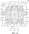
- Figure 1A is a cross-sectional view of a sealed electrical connector 100 (sometimes referred to herein simply as "connector 100") in accordance with one or more embodiments of the present disclosure.
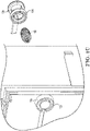
- Figure 1B is an isometric view of a sealed electrical connector in accordance with one or more embodiments of the present disclosure.
- Figure 1C is an exploded isometric view of a sealed electrical connector in accordance with one or more embodiments of the present disclosure.
- Figures 1A , 1B , and 1C may be cumulatively referred to herein as " Figure 1 .”
- the connector includes a spring 102 extending between a first spring contact point 140 (sometimes referred to herein simply as “first contact 140”) of a first PCB 136 and a second spring contact point 142 (sometimes referred to herein simply as “second contact 142”) of a second PCB 138.
- the spring is at least partially compressed, as shown in Figure 1A , to provide reliable contact with the first contact 140 and the second contact 142.
- the spring 102 can be a double conic spring, as shown in Figure 1 , though it is noted that embodiments herein are not so limited.
- the spring 102 includes a middle portion 108 and two opposing end portions: a first end portion 104 and a second end portion 106.
- the middle portion 108 includes a plurality of coils of a first diameter 112.
- each of the first end portion 104 and the second end portion 106 can include a plurality of coils that taper in diameter from the first diameter 112 to a second diameter 110 at their respective terminal ends.
- the first end portion 104 and the second end portion 106 taper to different diameters.
- the size of the second diameter 110 can be selected based on a size of the first contact 140 and/or the second contact 142. It should be appreciated that the first contact 140 and the second contact 142 can be a same size or different sizes. Additionally, it is noted that while the middle portion 108 is shown as having a substantially continuous diameter 112, embodiments herein are not so limited; the diameter 112 of the middle portion 108 may taper or otherwise vary along a length of the middle portion 108.
- the spring 102 is made of a tinned phosphorous bronze material. In some embodiments, a material comprising the spring 102 is selected based on a material comprising the first contact 140 and/or the second contact 142.
- the spring 102, the first contact 140, and the second contact 142 are made of a same material. Utilizing a same material (e.g., a same alloy) can reduce galvanic corrosion and can increase conductivity through the connector 100 by reducing capacitance and/or resistance.
- the first PCB 136 and the second PCB 138 can be substantially parallel, as shown in Figure 1A , though it is noted that embodiments herein are not so limited.
- the first PCB 136 and the second PCB 138 can be at a different angle and/or position with respect to one another.
- the term "PCB" refers to a device to mechanically support and electrically connect electrical components via conductive traces.
- the first PCB 136 and/or second PCB 138 can include electrical components utilized in detection of smoke via the aspirating smoke detector device.
- an aspirating smoke detector device can include a blower and sensor head housings.
- the first PCB 136 and/or second PCB 138 can be utilized to control the blower (e.g., the speed of the blower), receive signals from the sensor head housings, etc.
- the first PCB 136 and/or second PCB 138 can, accordingly, be utilized to control operation of the aspirating smoke detector device to detect smoke particles in a gas flowing through the aspirating smoke detector device and transmit a signal to a control panel in response to detection of smoke particles in the gas.
- the first PCB 136 and/or second PCB 138 can include buttons, light emitting diodes (LEDs), and/or other electrical components known to those of skill in the art.
- the middle portion 108 of the spring 102 is surrounded by a spacer 114.
- the spacer 114 is a portion of a manifold (e.g., integrated in the manifold 102, discussed below).
- the term "manifold" refers to a device including at least one inlet and at least one outlet.
- a manifold can make up a portion of the aspirating smoke detector device and can include various parts, including a flow path, a blower housing, a first sensor head housing, and a second sensor head housing, as are further described herein.
- the spacer 114 can be manufactured of a plastic material.
- the spacer 114 can be manufactured from acrylonitrile butadiene styrene (ABS) plastic, poly(methyl methacrylate) (PMMA) plastic, thermoplastic elastomers (TPE), among other types of plastic materials.
- ABS acrylonitrile butadiene styrene
- PMMA poly(methyl methacrylate)
- TPE thermoplastic elastomers
- the spacer 114 can be manufactured via multi-shot molding techniques, among other manufacturing techniques.
- the spacer 114 can define a cylindrical opening.
- the spacer 114 can include an inner surface defining a lumen having a diameter 116.
- the diameter 116 can exceed the diameter 112 of the middle portion 108 of the spring 102 such that the spring 102 can be inserted into the lumen.
- the diameter 116 may be selected to exceed the diameter 112 of the middle portion 108 by a relatively small amount (e.g., 1% to 10%) to prevent the spring 102 from overturning and/or moving within the spacer 114, which could cause contact with the first contact 140 and/or second contact 142 to be lost.
- the middle portion 108 of the spring 102 is surrounded by the spacer 114.
- portions of the first end portion 104 and/or second end portion 106 are also surrounded by the spacer 114.
- the first end portion 104 is surrounded by a first seal 124 and the second end portion 106 is surrounded by a second seal 126.
- the first seal 124 and the second seal 126 can be made of a thermoplastic rubber material. Some embodiments can include over-molding the first seal 124 and/or the second seal 126 to the spacer 114.
- the first seal 124 and the second seal 126 can be seated in grooves.
- the first seal 124 can include a first seating portion 128 configured to seat in a first groove 118.
- the second seal 126 can include a second seating portion 130 configured to seat in a second groove 120.
- Each of the first seal 124 and the second seal 126 can be compressed as the first PCB 136 is brought nearer to the second PCB 138. Accordingly, the spring 102 is hermetically sealed from outside air, smoke particles, and/or pollution by a combination of the spacer 114, the first seal 124, the second seal 126, the first PCB 136, and the second PCB 138.
- the second seal 126 includes a plurality of fins 134.
- the first seal 124 also includes a plurality of fins. Fins can be utilized to provide redundant and/or more reliable sealing from outside air. It is noted that some embodiments may not contain fins and that other features may be utilized to enhance sealing efficacy and may be dependent on the particular material used for the first seal 124 and/or the second seal 126.
- Embodiments herein can include components configured to retain the spring 102 within the lumen of the spacer 114. Such retention may be utilized during manufacture and/or assembly, for instance.
- the spacer 114 can include an annular projection 122.
- the annular projection 122 may be alternatively referred to as "ledge 122.”
- Ledge 122 can define a retaining diameter 123.
- the retaining diameter 123 is smaller than the diameter 112 of the middle portion of the spring 102 and larger than the diameter 110 of the first end portion 104. Accordingly, the spring 102 can be prevented from being removed from the lumen (e.g., from above) by the ledge 122.
- the second seal 126 can include a retaining lip 132.
- the retaining lip 132 can define a lip diameter 133.
- the lip diameter 133 is smaller than the diameter 112 of the middle portion of the spring 102 and larger than the diameter 110 of the second end portion 104. Accordingly, the spring 102 can be prevented from being removed from the lumen (e.g., from below) by the retaining lip 132.
- Such a configuration may be utilized in instances where the second PCB 138 is added (e.g., added last) to an assembly that includes the first PCB 136, the spacer 114, the first seal 124, and the second seal 126.
- the thermoplastic rubber material of the second seal 126 may allow the spring 102 to be inserted (e.g., pressed) into the lumen of the spacer 114 by temporarily deforming to a diameter sufficiently large to accept the middle portion 108 (e.g., a diameter temporarily larger than the lip diameter 133. Thereafter, the retaining lip returns to its normal shape and/or dimensions such that the lip diameter 133 is restored and the spring 102 is retained.
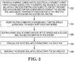
- Figure 2 is an example of a method of manufacturing a sealed electrical connector in accordance with one or more embodiments of the present disclosure.
- the method includes providing a spring configured to electrically connect a first printed circuit board (PCB) to a second PCB.
- the spring includes a first end portion configured to contact the first PCB, a second end portion configured to contact the second PCB, and a middle portion extending between the first end portion and the second end portion.
- the spring can be analogous to the spring 102, previously described in connection with Figure 1 .
- the method includes inserting the spring into a spacer such that the spacer surrounds the middle portion of the spring.
- Some embodiments can include inserting the spring into a lumen defined by an inner surface of the spacer.
- the spacer can include an annular projection defining a ledge that retains the spring in the lumen.
- at least one of the first and second seals includes a retaining lip that retains the spring in the lumen.
- the method includes seating a first seal in a first groove of the spacer and a second seal in a second groove of the spacer.
- the method can include over-molding the first and/or second seal to the spacer.
- the method includes force-fitting the first and/or second seals in the groove(s).
- the seals can be, for example, thermoplastic rubber seals.
- the method includes bringing the first seal into contact with the first PCB, and, at 260, bringing the second seal into contact with the second PCB.
- the PCBs can be brought into contact with the seals and with the spring 102 such that the seals are at least partially compressed around their entire circumference.
- the PCBs are between 10 and 12 millimeters apart.
- the PCBs are approximately 11 millimeters apart.
- the PCBs can be attached to larger components (e.g., manifolds, housings, etc.). In some embodiments, these components are secured together by one or more suitable fasteners.
- FIG 3 is an exploded view of an example of a portion of an aspirating smoke detector device 300, in accordance with one or more embodiments of the present disclosure.
- the aspirating smoke detector device 300 can include a manifold 302 and a PCB 312.
- the aspirating smoke detector device 300 can include a printed circuit board (PCB) 312.
- PCB printed circuit board
- the term "PCB” refers to a device to mechanically support and electrically connect electrical components via conductive traces.
- the PCB 312 can, therefore, include electrical components utilized in detection of smoke via the aspirating smoke detector device 300.
- the aspirating smoke detector device 300 can include a blower and sensor head housings.
- the PCB 312 can be utilized to control the blower (e.g., the speed of the blower), receive signals from the sensor head housings, etc.
- the PCB 312 can, accordingly, be utilized to control operation of the aspirating smoke detector device 300 to detect smoke particles in a gas flowing through the aspirating smoke detector device 300 and transmit a signal to a control panel in response to detection of smoke particles in the gas.
- the PCB 312 can include buttons (e.g., not illustrated in Figure 3 ), light emitting diodes (LEDs), among other electrical components.
- the aspirating smoke detector device 300 can further include a manifold 302.
- the term "manifold” refers to a device including at least one inlet and at least one outlet.
- the manifold 302 can make up a portion of the aspirating smoke detector device 300 and can include various parts, including a flow path 304, a blower housing 306, a first sensor head housing 308-1, and a second sensor head housing 308-2, as are further described herein.
- the manifold 302 can be manufactured of a plastic material.
- the manifold 302 can be manufactured from acrylonitrile butadiene styrene (ABS) plastic, poly(methyl methacrylate) (PMMA) plastic, thermoplastic elastomers (TPE), among other types of plastic materials.
- ABS acrylonitrile butadiene styrene
- PMMA poly(methyl methacrylate)
- TPE thermoplastic elastomers
- the manifold 302 can be made of any other type of material (e.g., metal, carbon fiber, etc.).
- the manifold 302 can be manufactured via multi-shot molding techniques, for instance.
- a flow path 304 can be included as part of the manifold 302.
- the flow path 304 can include a first flow channel 305-1 and a second flow channel 305-2 (referred to collectively herein as flow channels 305).
- the flow channels 305 can allow for the flow of gas through the aspirating smoke detector device 300. For instance, gas can flow into and out of different portions of the aspirating smoke detector device 300 through the flow channels 305 for smoke detection, as is further described herein.
- the manifold 302 can include light pipes 314-1 and 314-2.
- the term "light pipe” refers to a device to transmit light for the purpose of illumination.
- the light pipes 314 can be of a transparent material to allow light (e.g., from an LED of the PCB 312) to be transmitted.
- the light pipes 314-1 can be in a 2x2 array configuration and the light pipes 314-2 can be in a 1x1 array configuration.
- the manifold 302 can include a blower housing 306.
- the blower housing 306 can be configured to receive a blower (e.g., not illustrated in Figure 3 ).
- the blower can operate to draw gas into and cause gas to flow through the aspirating smoke detector device 300.
- the blower housing 306 can include a blower housing outlet 311. The gas flowing through the aspirating smoke detector device 300 can exit the aspirating smoke detector device through the blower housing outlet 311.
- the first flow channel 305-1 can connect the blower housing 306 to a first sensor head housing 308-1.
- the first sensor head housing 308-1 can be configured to receive a sensor head (e.g., not illustrated in Figure 3 ).
- the first sensor head housing 308-1 can include a first sensor head housing inlet 310-1.
- the blower can operate to draw gas into a sensor head located in the first sensor head housing 308-1 via the first sensor head housing inlet 310-1 and out of the first sensor head housing 308-1 via the first flow channel 305-1 for detection of smoke particles in the gas.
- the second flow channel 305-2 can connect the blower housing 306 to a second sensor head housing 308-2.
- the second sensor head housing 308-2 can also be configured to receive a sensor head (e.g., not illustrated in Figure 3 ).
- the second sensor head housing 308-2 can include a second sensor head housing inlet 310-2.
- the blower can operate to draw gas into another sensor head located in the second sensor head housing 308-2 via the second sensor head housing inlet 310-2 and out of the second sensor head housing 308-2 via the second flow channel 305-2 for detection of smoke particles in the gas.
- the manifold 302 can further include a gasket 316.
- gasket refers to a device located around an area of another device to make the area impervious to the transition of fluid through or around the device.
- the gasket 316 can be located on a "back" side of the manifold 302 which is to interface (e.g., rest against) the PCB 312.
- the gasket 316 can fluidically seal the manifold 302 to the PCB 312, as is further described in connection with Figure 4 .
- Figure 4 is an exploded view of an example of a manifold 402 and a printed circuit board (PCB) 412 of an aspirating smoke detector device 400, in accordance with one or more embodiments of the present disclosure.
- the manifold 402 can include a gasket 416.
- the manifold 402 can include a gasket 416.
- the gasket 416 can be utilized to fluidically seal the manifold 402 to the PCB 412.
- the manifold 402 can be positioned adjacent to (e.g., resting against) the PCB 412.
- the gasket 416 can be compressed against the PCB 412 to cause the gasket 416 to fluidically seal the manifold 402 to the PCB 412.
- the gasket 416 can be a thermo-plastic rubber gasket.
- the gasket 416 can be created on the manifold 402 via molding techniques, for instance.
- the gasket 416 is described as a thermo-plastic rubber gasket, embodiments of the present disclosure are not so limited.
- the gasket 416 can be any other material that can fluidically seal the manifold 402 to the PCB 412.
- Fluidically sealing the manifold 402 to the PCB 412 can prevent substances from transiting between the gasket 416 into a space between the manifold 402 and the PCB 412. Such a fluidically sealed space can prevent moisture from entering the space. Accordingly, the gasket 416 can guard against moisture interacting with the PCB 412, preventing shorting of the electrical components of the PCB 412, preventing corrosion of the PCB 412, etc.
- Figure 5 is an exploded view of an example of a manifold 502, a blower 507, and sensor heads 509 of an aspirating smoke detector device 500, in accordance with one or more embodiments of the present disclosure.
- the aspirating smoke detector device 500 can include a manifold 502.
- the aspirating smoke detector device 500 can include a manifold 502, the manifold including a flow path 504, a blower housing 506, a first sensor head housing 508-1, and a second sensor head housing 508-2.
- the manifold 502 can cover the PCB 512.
- the flow path 504 can include the first flow channel 505-1 and the second flow channel 505-2.
- the manifold 502 can include the blower housing 506.
- the blower housing 506 is configured to receive the blower 507.
- the term "blower” refers to a mechanical device for moving gas in a particular direction.
- the blower 507 can be utilized to move gas through the aspirating smoke detector device 500.
- the blower 507 can, in some instances, comprise a ducted housing having a fan that, when spinning, causes gas (e.g., such as air) to flow in a particular direction.
- the blower housing 506 is configured to receive the blower 507 when the blower 507 is oriented in a particular configuration.
- the blower housing 506 can be designed such that the blower 507 can fit into the blower housing 506 in a single orientation. This can prevent the blower 507 from being installed in the blower housing 506 in an incorrect orientation.
- the blower housing 506 can include a blower cover gasket 518.
- the blower cover gasket 518 can be formed on the blower housing 506 by, for instance, molding techniques.
- the blower cover gasket 518 can be, for example, a thermoplastic rubber gasket, among other examples.
- the manifold 502 can additionally include the first sensor head housing 508-1.
- the first sensor head housing 508-1 can be connected to the blower housing 506 via the first flow channel 505-1 and can receive a first sensor head 509-1.
- the term "sensor head” refers to a device to detect events and/or changes in its environment and transmit the detected events and/or changes for processing and/or analysis.
- the sensor heads 509 can be utilized to detect smoke particles in gas transiting through the aspirating smoke detector device 500.
- the first sensor head 509-1 can be a nephelometer (e.g., an aerosol photometer) to measure the concentration of smoke particles in a gas by utilizing light scattered by smoke particles.
- the first sensor head 509-1 can be any other type of smoke detection sensor that detects smoke utilizing gas transiting through the aspirating smoke detector device 500.
- the first sensor head housing 508-1 can be configured to receive a first sensor head 509-1. That is, the first sensor head housing 508-1 is configured to receive the first sensor head 509-1 when the first sensor head 509-1 is oriented in a particular configuration.
- the first sensor head housing 508-1 can be designed such that the first sensor head 509-1 can fit into the first sensor head housing 508-1 in a single orientation. This can prevent the first sensor head 509-1 from being installed in the first sensor head housing 508-1 in an incorrect orientation.
- the first sensor head housing 508-1 can include a first sensor head housing cover gasket 520-1.
- the first sensor head housing cover gasket 520-1 can be formed on the first sensor head housing 508-1 by, for instance, molding techniques.
- the first sensor head housing cover gasket 520-1 can be, for example, a thermoplastic rubber gasket, among other examples.
- the second sensor head housing 508-2 can be connected to the blower housing 506 via the second flow channel 505-2 and can receive a second sensor head 509-2.
- the second sensor head 509-2 can be a nephelometer or any other type of smoke detection sensor that detects smoke utilizing gas transiting through the aspirating smoke detector device 500.
- the second sensor head housing 508-2 can be configured to receive the second sensor head 509-2. That is, the second sensor head housing 508-2 is configured to receive the second sensor head 509-2 when the second sensor head 509-2 is oriented in a particular configuration.
- the second sensor head housing 508-2 can be designed such that the second sensor head 509-2 can fit into the second sensor head housing 508-2 in a single orientation. This can prevent the second sensor head 509-2 from being installed in the second sensor head housing 508-2 in an incorrect orientation.
- the second sensor head housing 508-2 can include a second sensor head housing cover gasket 520-2.
- the second sensor head housing cover gasket 520-2 can be formed on the second sensor head housing 508-2 by, for instance, molding techniques.
- the second sensor head housing cover gasket 520-2 can be, for example, a thermoplastic rubber gasket, among other examples.
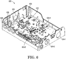
- FIG. 6 is perspective view of an example of a housing 622 and a PCB 612 of an aspirating smoke detector device 600, in accordance with one or more embodiments of the present disclosure.
- the housing 622 can house the PCB 612, as is further described herein.
- the aspirating smoke detector device 600 can include a housing 622.
- the term "housing” refers to an outer shell of a device.
- the housing 622 can be a "rear" housing of the aspirating smoke detector device 600 which can house the PCB 612.
- the housing 622 can retain the PCB 612 after assembly of the aspirating smoke detector device 600.
- the PCB 612 can include LEDs 628-1 and 628-2.
- the LEDs 628-1 can be in a 2x2 array configuration to correspond with the 2x2 array configuration of the light pipes (e.g., light pipes 314-1, previously described in connection with Figure 3 ) and the LEDs 628-2 can be in a 1x1 array configuration to correspond with the 1x1 array configuration of the light pipes (e.g., light pipes 314-2, previously described in connection with Figure 3 ).
- the housing 622 can include a fastening mechanism.
- the fastening mechanism can retain the PCB 612 in the housing 622.
- the fastening mechanism can be, for example, a clamp(s), a snap clip, a mechanical fastener (e.g., a bolt, screw, etc.), among other types of fastening mechanisms.
- the housing 622 can include mounting locations.
- the mounting locations can include, for instance, a hole through which a fastener can secure the aspirating smoke detector device 600 to a wall or other object.
- the fastener can be secured to the wall or other object and slipped through the hole of the mounting location such that the housing 622 can rest on the fastener to mount the aspirating smoke detector device 600 to the wall or other object.
- the housing 622 can include a first housing inlet 624-1, a second housing inlet 624-2, and a housing outlet 626.
- the first housing inlet 624-1, the second housing inlet 624-2, and the housing outlet 626 can be apertures in the structure of the housing 622.
- the first housing inlet 624-1 can receive a first sensor head housing inlet
- the second housing inlet 624-2 can receive a second sensor head housing inlet
- the housing outlet 626 can receive a blower housing outlet, as is further described in connection with Figure 7 .
- the housing 622 can further include snap clips 630.
- snap clip refers to a fastening mechanism including a protruding flange having an engagement tooth.
- the snap clips 630 can be deflected when an object to be secured is inserted adjacent to the snap clips 630 and an engagement tooth of each of the snap clips can engage with a surface of the object to secure the object, as is further described in connection with Figure 7 .
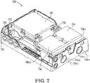
- Figure 7 is a perspective view of an example of a housing 722 and a manifold 702 of an aspirating smoke detector device 700 having a blower housing cover 732 and sensor head housing cover 734, in accordance with one or more embodiments of the present disclosure.
- the manifold 702 can include a blower housing 706 and sensor head housings 708.
- the aspirating smoke detector device 700 can be partially assembled.
- the manifold 702 can be connected to the housing 722 via a snap clip (e.g., snap clip 630, previously described in connection with Figure 6 ).
- the snap clip can be deflected when the manifold 702 is inserted into the housing 722 and an engagement tooth of the snap clip can engage with a surface of the manifold 702 to connect the manifold 702 to the housing 722.
- the first sensor head housing inlet 710-1 can be coaxially located with the first housing inlet 724-1.
- the second sensor head housing inlet 710-2 can be coaxially located with the second housing inlet 724-2.
- a blower housing outlet can be coaxially located with the housing outlet (e.g., housing outlet 626, previously described in connection with Figure 6 ).
- gas can flow into the aspirating smoke detector device 700 via the first sensor head housing inlet 710-1 and/or the second sensor head housing inlet 710-2, to the sensor heads located in the sensor head housings 708, through the flow channels, and out the blower housing outlet, during which time the sensor heads can determine whether the gas includes smoke particles.
- the various housings comprising the manifold 702 can be fluidically sealed.
- the blower housing 706 can receive a blower housing cover 732.
- the blower housing 706 can include a cover gasket (e.g., blower cover gasket 518, previously described in connection with Figure 5 ).
- cover gasket e.g., blower cover gasket 518, previously described in connection with Figure 5 .
- the first sensor head housing 708-1 and the second sensor head housing 708-2 can receive a sensor head housing cover 734 to cover the first sensor head and the second sensor head respectively located therein.
- the first sensor head housing 708-1 and the second sensor head housing 708-2 can include a cover gasket (e.g., first sensor head housing cover gasket 520-1, previously described in connection with Figure 5 ).
- the sensor head housing cover gasket can fluidically seal the first sensor head housing 708-1 and the second sensor head housing 708-2 to the sensor head housing cover 734.
Landscapes
- Chemical & Material Sciences (AREA)
- Analytical Chemistry (AREA)
- Business, Economics & Management (AREA)
- Emergency Management (AREA)
- Physics & Mathematics (AREA)
- General Physics & Mathematics (AREA)
- Fire-Detection Mechanisms (AREA)
Applications Claiming Priority (1)
| Application Number | Priority Date | Filing Date | Title |
|---|---|---|---|
| US17/335,507 US11605916B2 (en) | 2021-06-01 | 2021-06-01 | Sealed electrical connector |
Publications (2)
| Publication Number | Publication Date |
|---|---|
| EP4099511A1 true EP4099511A1 (de) | 2022-12-07 |
| EP4099511B1 EP4099511B1 (de) | 2025-04-16 |
Family
ID=81877839
Family Applications (1)
| Application Number | Title | Priority Date | Filing Date |
|---|---|---|---|
| EP22176835.1A Active EP4099511B1 (de) | 2021-06-01 | 2022-06-01 | Abgedichteter elektrischer verbinder |
Country Status (3)
| Country | Link |
|---|---|
| US (2) | US11605916B2 (de) |
| EP (1) | EP4099511B1 (de) |
| CN (1) | CN115441248B (de) |
Families Citing this family (2)
| Publication number | Priority date | Publication date | Assignee | Title |
|---|---|---|---|---|
| US11605916B2 (en) * | 2021-06-01 | 2023-03-14 | Honeywell International Inc. | Sealed electrical connector |
| CN117231067B (zh) * | 2022-12-12 | 2026-01-02 | 温州源飞宠物玩具制品股份有限公司 | 一种锁止组件 |
Citations (5)
| Publication number | Priority date | Publication date | Assignee | Title |
|---|---|---|---|---|
| US5427535A (en) * | 1993-09-24 | 1995-06-27 | Aries Electronics, Inc. | Resilient electrically conductive terminal assemblies |
| US6174172B1 (en) * | 1995-12-28 | 2001-01-16 | Nhk Spring Co., Ltd. | Electric contact unit |
| JP2004296301A (ja) * | 2003-03-27 | 2004-10-21 | Enplas Corp | コンタクトユニット |
| US20080143356A1 (en) * | 2006-10-18 | 2008-06-19 | William Louis Brodsky | Conductive Particle Filled Polymer Electrical Contact |
| US20110207343A1 (en) * | 2010-02-23 | 2011-08-25 | Yung-Chi Tsai | Contact-type electronic inspection module |
Family Cites Families (35)
| Publication number | Priority date | Publication date | Assignee | Title |
|---|---|---|---|---|
| GB2029651B (en) * | 1978-09-07 | 1982-11-10 | Standard Telephones Cables Ltd | Demountable connectors for submarine repeaters |
| DE3508111A1 (de) * | 1985-03-07 | 1986-09-11 | PTR-Meßtechnik GmbH, 4712 Werne | Vorrichtung zum pruefen von leiterplatten |
| US4914555A (en) * | 1989-07-20 | 1990-04-03 | Gammache Richard J | Rechargeable flashlight |
| EP0462706A1 (de) * | 1990-06-11 | 1991-12-27 | ITT INDUSTRIES, INC. (a Delaware corporation) | Kontaktanordnung |
| DE4428694C2 (de) | 1994-08-12 | 1996-06-20 | Wagner Alarm Sicherung | Luftdruckkompensierte Branderkennungsvorrichtung und Verfahren |
| CA2291203A1 (en) | 1998-12-04 | 2000-06-04 | George A. Schoenfelder | Aspirated detector with flow sensor |
| US6254435B1 (en) * | 1999-06-01 | 2001-07-03 | Molex Incorporated | Edge card connector for a printed circuit board |
| US6497582B1 (en) * | 2001-08-22 | 2002-12-24 | International Business Machines Corporation | LGA connector with integrated gasket |
| US6843658B2 (en) * | 2002-04-02 | 2005-01-18 | Citizen Electronics Co., Ltd. | Electric connector for connecting electronic instruments |
| US20040157476A1 (en) * | 2003-02-12 | 2004-08-12 | Ralph Maldonado | Perimeter sealed high density multi-pin connector |
| US7128592B2 (en) * | 2004-07-09 | 2006-10-31 | Che Yu Li & Company, Llc | Interconnection device and system |
| FR2880511A1 (fr) * | 2005-01-04 | 2006-07-07 | Jean Pierre Christian Choplet | Systeme d'entretoises specifiques permettant un empilage de circuits imprimes dans un volume minimum |
| JP2007258028A (ja) * | 2006-03-24 | 2007-10-04 | Morimatsu:Kk | コネクタ |
| JP5197754B2 (ja) * | 2009-11-13 | 2013-05-15 | テスト ツーリング ソリューションズ グループ ピイ ティ イー リミテッド | プローブピン |
| WO2011064628A1 (en) * | 2009-11-30 | 2011-06-03 | Fci Automotive Holding | Seal, system and connector assembly comprising such a seal, methods of assembly and of manufacture |
| FR2962601B1 (fr) * | 2010-07-06 | 2013-06-14 | Thales Sa | Connecteur d'ensembles electroniques blindant et sans soudure electrique |
| ES2394872T3 (es) | 2010-07-15 | 2013-02-06 | Siemens Schweiz Ag | Detección de obstrucciones e interrupciones de un detector de humo aspirado (ASD) |
| DE102011006867A1 (de) * | 2011-04-06 | 2012-10-11 | Robert Bosch Gmbh | Steckverbinder zur Direktkontaktierung auf einer Leiterplatte |
| US8779295B2 (en) * | 2012-03-27 | 2014-07-15 | Kang Yang Hardware Enterprises Co., Ltd. | Partition post used on printed circuit board |
| US8708726B2 (en) * | 2012-08-01 | 2014-04-29 | Itt Manufacturing Enterprises Llc | Electrical connector system with replaceable sealing element |
| CN102810782B (zh) * | 2012-08-22 | 2014-12-17 | 深圳市簧中簧电子有限公司 | 导电端子、安装有导电端子的电路板和板对板连接器 |
| US8956193B2 (en) * | 2012-12-12 | 2015-02-17 | Intel Corporation | Helicoil spring backing socket |
| US9039448B2 (en) * | 2013-02-18 | 2015-05-26 | Tyco Electronics Corporation | Electronic interconnect devices having conductive vias |
| US9391409B2 (en) * | 2014-05-22 | 2016-07-12 | Yazaki Corporation | Electronic device connector |
| US10115280B2 (en) | 2014-06-26 | 2018-10-30 | Life Safety Distribution Ag | Detector with optical block |
| JP6720187B2 (ja) * | 2014-09-16 | 2020-07-08 | アンフェノール・エフシーアイ・アジア・ピーティーイー.・リミテッドAmphenol FCI Asia Pte.Ltd. | 密閉してシールされた電気コネクタアセンブリ |
| US9824564B2 (en) | 2015-12-14 | 2017-11-21 | Honeywell International Inc. | Aspirated smoke detector with improved optical chamber |
| US9728865B1 (en) * | 2016-04-12 | 2017-08-08 | Symbol Technologies, Llc | Sealed, solderless, replaceable, electrical connector |
| CN205857282U (zh) * | 2016-06-13 | 2017-01-04 | 佛山市丁普乐电器有限公司 | 原水箱出水装置及移动式净水器 |
| US10877011B2 (en) | 2016-06-29 | 2020-12-29 | Nexceris, Llc | Systems and methods for monitoring for a gas analyte |
| CN206148669U (zh) * | 2016-11-07 | 2017-05-03 | 佛山市汇莱德电器有限公司 | 防水五极电连接器下座 |
| US10608354B2 (en) * | 2017-03-23 | 2020-03-31 | Verily Life Sciences Llc | Implantable connector with two electrical components |
| US11231403B2 (en) | 2018-10-16 | 2022-01-25 | Novinium, Inc. | Methods of using dilution of a second type to calibrate one or more sensors |
| CN210992079U (zh) * | 2019-08-28 | 2020-07-14 | 南京仙能医疗科技有限公司 | 一种自吸附拔罐温热电疗电极 |
| US11605916B2 (en) * | 2021-06-01 | 2023-03-14 | Honeywell International Inc. | Sealed electrical connector |
-
2021
- 2021-06-01 US US17/335,507 patent/US11605916B2/en active Active
-
2022
- 2022-06-01 CN CN202210618752.9A patent/CN115441248B/zh active Active
- 2022-06-01 EP EP22176835.1A patent/EP4099511B1/de active Active
-
2023
- 2023-03-14 US US18/121,105 patent/US11888258B2/en active Active
Patent Citations (5)
| Publication number | Priority date | Publication date | Assignee | Title |
|---|---|---|---|---|
| US5427535A (en) * | 1993-09-24 | 1995-06-27 | Aries Electronics, Inc. | Resilient electrically conductive terminal assemblies |
| US6174172B1 (en) * | 1995-12-28 | 2001-01-16 | Nhk Spring Co., Ltd. | Electric contact unit |
| JP2004296301A (ja) * | 2003-03-27 | 2004-10-21 | Enplas Corp | コンタクトユニット |
| US20080143356A1 (en) * | 2006-10-18 | 2008-06-19 | William Louis Brodsky | Conductive Particle Filled Polymer Electrical Contact |
| US20110207343A1 (en) * | 2010-02-23 | 2011-08-25 | Yung-Chi Tsai | Contact-type electronic inspection module |
Also Published As
| Publication number | Publication date |
|---|---|
| US20220384985A1 (en) | 2022-12-01 |
| US20230216235A1 (en) | 2023-07-06 |
| EP4099511B1 (de) | 2025-04-16 |
| CN115441248B (zh) | 2025-08-08 |
| US11888258B2 (en) | 2024-01-30 |
| US11605916B2 (en) | 2023-03-14 |
| CN115441248A (zh) | 2022-12-06 |
Similar Documents
| Publication | Publication Date | Title |
|---|---|---|
| US12165484B2 (en) | Aspirating smoke detector device | |
| US11888258B2 (en) | Sealed electrical connector | |
| US11435217B2 (en) | Visual liquid level indicator | |
| US11867532B2 (en) | Aspirating smoke detector packaging | |
| JP4131231B2 (ja) | 漏液検出器 | |
| US10197465B2 (en) | O-ring internal seal for pressure sensor | |
| US11900776B2 (en) | Lid of an aspirating smoke detector device | |
| AU2025283455A1 (en) | Alarm with Obstacle Detection Function | |
| CN116490908B (zh) | 防灾设备 | |
| JP7604276B2 (ja) | 導電性粒体検出装置、及び、減速機 | |
| JP3362324B2 (ja) | 火災検出装置 | |
| JP3747805B2 (ja) | 浴室内監視装置 | |
| US20110210854A1 (en) | Building safety detector assembly | |
| WO2025076388A1 (en) | Smoke chamber | |
| CN219475539U (zh) | 一种气体测量装置 | |
| JP2016192066A (ja) | 火災受信機 | |
| JP3407093B2 (ja) | 火災検出装置 | |
| JP3517590B2 (ja) | 感知器のled固定構造 | |
| JP3362323B2 (ja) | 火災検出装置 | |
| CN117760643A (zh) | 一种进水快速检测反应装置 | |
| CN121617195A (zh) | 火灾报警器和火灾报警系统 | |
| JPH08241474A (ja) | 火災検出装置 | |
| CN118648039A (zh) | 火灾侦测装置 | |
| WO2006078204A1 (en) | Fluid detector | |
| TW202029141A (zh) | 警報裝置 |
Legal Events
| Date | Code | Title | Description |
|---|---|---|---|
| PUAI | Public reference made under article 153(3) epc to a published international application that has entered the european phase |
Free format text: ORIGINAL CODE: 0009012 |
|
| STAA | Information on the status of an ep patent application or granted ep patent |
Free format text: STATUS: REQUEST FOR EXAMINATION WAS MADE |
|
| 17P | Request for examination filed |
Effective date: 20220601 |
|
| AK | Designated contracting states |
Kind code of ref document: A1 Designated state(s): AL AT BE BG CH CY CZ DE DK EE ES FI FR GB GR HR HU IE IS IT LI LT LU LV MC MK MT NL NO PL PT RO RS SE SI SK SM TR |
|
| P01 | Opt-out of the competence of the unified patent court (upc) registered |
Effective date: 20230523 |
|
| GRAP | Despatch of communication of intention to grant a patent |
Free format text: ORIGINAL CODE: EPIDOSNIGR1 |
|
| STAA | Information on the status of an ep patent application or granted ep patent |
Free format text: STATUS: GRANT OF PATENT IS INTENDED |
|
| RIC1 | Information provided on ipc code assigned before grant |
Ipc: G08B 17/107 20060101ALI20241028BHEP Ipc: H01R 13/73 20060101ALI20241028BHEP Ipc: H01R 13/52 20060101ALI20241028BHEP Ipc: H01R 13/33 20060101ALI20241028BHEP Ipc: H01R 13/24 20060101ALI20241028BHEP Ipc: H01R 12/71 20110101ALI20241028BHEP Ipc: H01R 12/70 20110101ALI20241028BHEP Ipc: H01R 12/91 20110101AFI20241028BHEP |
|
| INTG | Intention to grant announced |
Effective date: 20241112 |
|
| GRAS | Grant fee paid |
Free format text: ORIGINAL CODE: EPIDOSNIGR3 |
|
| GRAA | (expected) grant |
Free format text: ORIGINAL CODE: 0009210 |
|
| STAA | Information on the status of an ep patent application or granted ep patent |
Free format text: STATUS: THE PATENT HAS BEEN GRANTED |
|
| AK | Designated contracting states |
Kind code of ref document: B1 Designated state(s): AL AT BE BG CH CY CZ DE DK EE ES FI FR GB GR HR HU IE IS IT LI LT LU LV MC MK MT NL NO PL PT RO RS SE SI SK SM TR |
|
| REG | Reference to a national code |
Ref country code: GB Ref legal event code: FG4D |
|
| REG | Reference to a national code |
Ref country code: CH Ref legal event code: EP |
|
| REG | Reference to a national code |
Ref country code: IE Ref legal event code: FG4D |
|
| REG | Reference to a national code |
Ref country code: DE Ref legal event code: R096 Ref document number: 602022013122 Country of ref document: DE |
|
| PGFP | Annual fee paid to national office [announced via postgrant information from national office to epo] |
Ref country code: DE Payment date: 20250626 Year of fee payment: 4 |
|
| PGFP | Annual fee paid to national office [announced via postgrant information from national office to epo] |
Ref country code: FR Payment date: 20250624 Year of fee payment: 4 |
|
| PGFP | Annual fee paid to national office [announced via postgrant information from national office to epo] |
Ref country code: AT Payment date: 20250721 Year of fee payment: 4 |
|
| REG | Reference to a national code |
Ref country code: NL Ref legal event code: MP Effective date: 20250416 |
|
| PG25 | Lapsed in a contracting state [announced via postgrant information from national office to epo] |
Ref country code: NL Free format text: LAPSE BECAUSE OF FAILURE TO SUBMIT A TRANSLATION OF THE DESCRIPTION OR TO PAY THE FEE WITHIN THE PRESCRIBED TIME-LIMIT Effective date: 20250416 |
|
| REG | Reference to a national code |
Ref country code: AT Ref legal event code: MK05 Ref document number: 1786461 Country of ref document: AT Kind code of ref document: T Effective date: 20250416 |
|
| PG25 | Lapsed in a contracting state [announced via postgrant information from national office to epo] |
Ref country code: PT Free format text: LAPSE BECAUSE OF FAILURE TO SUBMIT A TRANSLATION OF THE DESCRIPTION OR TO PAY THE FEE WITHIN THE PRESCRIBED TIME-LIMIT Effective date: 20250818 Ref country code: FI Free format text: LAPSE BECAUSE OF FAILURE TO SUBMIT A TRANSLATION OF THE DESCRIPTION OR TO PAY THE FEE WITHIN THE PRESCRIBED TIME-LIMIT Effective date: 20250416 Ref country code: ES Free format text: LAPSE BECAUSE OF FAILURE TO SUBMIT A TRANSLATION OF THE DESCRIPTION OR TO PAY THE FEE WITHIN THE PRESCRIBED TIME-LIMIT Effective date: 20250416 |
|
| REG | Reference to a national code |
Ref country code: LT Ref legal event code: MG9D |
|
| PG25 | Lapsed in a contracting state [announced via postgrant information from national office to epo] |
Ref country code: NO Free format text: LAPSE BECAUSE OF FAILURE TO SUBMIT A TRANSLATION OF THE DESCRIPTION OR TO PAY THE FEE WITHIN THE PRESCRIBED TIME-LIMIT Effective date: 20250716 Ref country code: GR Free format text: LAPSE BECAUSE OF FAILURE TO SUBMIT A TRANSLATION OF THE DESCRIPTION OR TO PAY THE FEE WITHIN THE PRESCRIBED TIME-LIMIT Effective date: 20250717 |
|
| PG25 | Lapsed in a contracting state [announced via postgrant information from national office to epo] |
Ref country code: PL Free format text: LAPSE BECAUSE OF FAILURE TO SUBMIT A TRANSLATION OF THE DESCRIPTION OR TO PAY THE FEE WITHIN THE PRESCRIBED TIME-LIMIT Effective date: 20250416 |
|
| PG25 | Lapsed in a contracting state [announced via postgrant information from national office to epo] |
Ref country code: BG Free format text: LAPSE BECAUSE OF FAILURE TO SUBMIT A TRANSLATION OF THE DESCRIPTION OR TO PAY THE FEE WITHIN THE PRESCRIBED TIME-LIMIT Effective date: 20250416 |
|
| PG25 | Lapsed in a contracting state [announced via postgrant information from national office to epo] |
Ref country code: HR Free format text: LAPSE BECAUSE OF FAILURE TO SUBMIT A TRANSLATION OF THE DESCRIPTION OR TO PAY THE FEE WITHIN THE PRESCRIBED TIME-LIMIT Effective date: 20250416 Ref country code: AT Free format text: LAPSE BECAUSE OF FAILURE TO SUBMIT A TRANSLATION OF THE DESCRIPTION OR TO PAY THE FEE WITHIN THE PRESCRIBED TIME-LIMIT Effective date: 20250416 |
|
| PG25 | Lapsed in a contracting state [announced via postgrant information from national office to epo] |
Ref country code: RS Free format text: LAPSE BECAUSE OF FAILURE TO SUBMIT A TRANSLATION OF THE DESCRIPTION OR TO PAY THE FEE WITHIN THE PRESCRIBED TIME-LIMIT Effective date: 20250716 |
|
| PG25 | Lapsed in a contracting state [announced via postgrant information from national office to epo] |
Ref country code: IS Free format text: LAPSE BECAUSE OF FAILURE TO SUBMIT A TRANSLATION OF THE DESCRIPTION OR TO PAY THE FEE WITHIN THE PRESCRIBED TIME-LIMIT Effective date: 20250816 |
|
| PG25 | Lapsed in a contracting state [announced via postgrant information from national office to epo] |
Ref country code: LV Free format text: LAPSE BECAUSE OF FAILURE TO SUBMIT A TRANSLATION OF THE DESCRIPTION OR TO PAY THE FEE WITHIN THE PRESCRIBED TIME-LIMIT Effective date: 20250416 |
|
| PG25 | Lapsed in a contracting state [announced via postgrant information from national office to epo] |
Ref country code: SM Free format text: LAPSE BECAUSE OF FAILURE TO SUBMIT A TRANSLATION OF THE DESCRIPTION OR TO PAY THE FEE WITHIN THE PRESCRIBED TIME-LIMIT Effective date: 20250416 Ref country code: DK Free format text: LAPSE BECAUSE OF FAILURE TO SUBMIT A TRANSLATION OF THE DESCRIPTION OR TO PAY THE FEE WITHIN THE PRESCRIBED TIME-LIMIT Effective date: 20250416 |
|
| REG | Reference to a national code |
Ref country code: DE Ref legal event code: R097 Ref document number: 602022013122 Country of ref document: DE |
|
| PG25 | Lapsed in a contracting state [announced via postgrant information from national office to epo] |
Ref country code: CZ Free format text: LAPSE BECAUSE OF FAILURE TO SUBMIT A TRANSLATION OF THE DESCRIPTION OR TO PAY THE FEE WITHIN THE PRESCRIBED TIME-LIMIT Effective date: 20250416 |
|
| PG25 | Lapsed in a contracting state [announced via postgrant information from national office to epo] |
Ref country code: EE Free format text: LAPSE BECAUSE OF FAILURE TO SUBMIT A TRANSLATION OF THE DESCRIPTION OR TO PAY THE FEE WITHIN THE PRESCRIBED TIME-LIMIT Effective date: 20250416 |
|
| PG25 | Lapsed in a contracting state [announced via postgrant information from national office to epo] |
Ref country code: SK Free format text: LAPSE BECAUSE OF FAILURE TO SUBMIT A TRANSLATION OF THE DESCRIPTION OR TO PAY THE FEE WITHIN THE PRESCRIBED TIME-LIMIT Effective date: 20250416 |
|
| REG | Reference to a national code |
Ref country code: CH Ref legal event code: H13 Free format text: ST27 STATUS EVENT CODE: U-0-0-H10-H13 (AS PROVIDED BY THE NATIONAL OFFICE) Effective date: 20260127 |
|
| PG25 | Lapsed in a contracting state [announced via postgrant information from national office to epo] |
Ref country code: IT Free format text: LAPSE BECAUSE OF FAILURE TO SUBMIT A TRANSLATION OF THE DESCRIPTION OR TO PAY THE FEE WITHIN THE PRESCRIBED TIME-LIMIT Effective date: 20250416 |
|
| PG25 | Lapsed in a contracting state [announced via postgrant information from national office to epo] |
Ref country code: MC Free format text: LAPSE BECAUSE OF FAILURE TO SUBMIT A TRANSLATION OF THE DESCRIPTION OR TO PAY THE FEE WITHIN THE PRESCRIBED TIME-LIMIT Effective date: 20250416 |
|
| PG25 | Lapsed in a contracting state [announced via postgrant information from national office to epo] |
Ref country code: RO Free format text: LAPSE BECAUSE OF FAILURE TO SUBMIT A TRANSLATION OF THE DESCRIPTION OR TO PAY THE FEE WITHIN THE PRESCRIBED TIME-LIMIT Effective date: 20250416 |
|
| PG25 | Lapsed in a contracting state [announced via postgrant information from national office to epo] |
Ref country code: LU Free format text: LAPSE BECAUSE OF NON-PAYMENT OF DUE FEES Effective date: 20250601 |
|
| PLBE | No opposition filed within time limit |
Free format text: ORIGINAL CODE: 0009261 |
|
| STAA | Information on the status of an ep patent application or granted ep patent |
Free format text: STATUS: NO OPPOSITION FILED WITHIN TIME LIMIT |
|
| REG | Reference to a national code |
Ref country code: CH Ref legal event code: L10 Free format text: ST27 STATUS EVENT CODE: U-0-0-L10-L00 (AS PROVIDED BY THE NATIONAL OFFICE) Effective date: 20260225 |
|
| REG | Reference to a national code |
Ref country code: BE Ref legal event code: MM Effective date: 20250630 |
|
| 26N | No opposition filed |
Effective date: 20260119 |
|
| PG25 | Lapsed in a contracting state [announced via postgrant information from national office to epo] |
Ref country code: IE Free format text: LAPSE BECAUSE OF NON-PAYMENT OF DUE FEES Effective date: 20250601 |
|
| PG25 | Lapsed in a contracting state [announced via postgrant information from national office to epo] |
Ref country code: BE Free format text: LAPSE BECAUSE OF NON-PAYMENT OF DUE FEES Effective date: 20250630 |
|
| PG25 | Lapsed in a contracting state [announced via postgrant information from national office to epo] |
Ref country code: CH Free format text: LAPSE BECAUSE OF NON-PAYMENT OF DUE FEES Effective date: 20250630 |