EP4100277B1 - Module de stockage d'énergie de vehicule, bloc-batterie et véhicule - Google Patents
Module de stockage d'énergie de vehicule, bloc-batterie et véhicule Download PDFInfo
- Publication number
- EP4100277B1 EP4100277B1 EP20703968.6A EP20703968A EP4100277B1 EP 4100277 B1 EP4100277 B1 EP 4100277B1 EP 20703968 A EP20703968 A EP 20703968A EP 4100277 B1 EP4100277 B1 EP 4100277B1
- Authority
- EP
- European Patent Office
- Prior art keywords
- battery
- casing
- energy storage
- heat pipe
- heat
- Prior art date
- Legal status (The legal status is an assumption and is not a legal conclusion. Google has not performed a legal analysis and makes no representation as to the accuracy of the status listed.)
- Active
Links
Images
Classifications
-
- H—ELECTRICITY
- H01—ELECTRIC ELEMENTS
- H01M—PROCESSES OR MEANS, e.g. BATTERIES, FOR THE DIRECT CONVERSION OF CHEMICAL ENERGY INTO ELECTRICAL ENERGY
- H01M10/00—Secondary cells; Manufacture thereof
- H01M10/60—Heating or cooling; Temperature control
- H01M10/65—Means for temperature control structurally associated with the cells
- H01M10/655—Solid structures for heat exchange or heat conduction
- H01M10/6552—Closed pipes transferring heat by thermal conductivity or phase transition, e.g. heat pipes
-
- B—PERFORMING OPERATIONS; TRANSPORTING
- B60—VEHICLES IN GENERAL
- B60L—PROPULSION OF ELECTRICALLY-PROPELLED VEHICLES; SUPPLYING ELECTRIC POWER FOR AUXILIARY EQUIPMENT OF ELECTRICALLY-PROPELLED VEHICLES; ELECTRODYNAMIC BRAKE SYSTEMS FOR VEHICLES IN GENERAL; MAGNETIC SUSPENSION OR LEVITATION FOR VEHICLES; MONITORING OPERATING VARIABLES OF ELECTRICALLY-PROPELLED VEHICLES; ELECTRIC SAFETY DEVICES FOR ELECTRICALLY-PROPELLED VEHICLES
- B60L50/00—Electric propulsion with power supplied within the vehicle
- B60L50/50—Electric propulsion with power supplied within the vehicle using propulsion power supplied by batteries or fuel cells
- B60L50/60—Electric propulsion with power supplied within the vehicle using propulsion power supplied by batteries or fuel cells using power supplied by batteries
- B60L50/64—Constructional details of batteries specially adapted for electric vehicles
-
- B—PERFORMING OPERATIONS; TRANSPORTING
- B60—VEHICLES IN GENERAL
- B60L—PROPULSION OF ELECTRICALLY-PROPELLED VEHICLES; SUPPLYING ELECTRIC POWER FOR AUXILIARY EQUIPMENT OF ELECTRICALLY-PROPELLED VEHICLES; ELECTRODYNAMIC BRAKE SYSTEMS FOR VEHICLES IN GENERAL; MAGNETIC SUSPENSION OR LEVITATION FOR VEHICLES; MONITORING OPERATING VARIABLES OF ELECTRICALLY-PROPELLED VEHICLES; ELECTRIC SAFETY DEVICES FOR ELECTRICALLY-PROPELLED VEHICLES
- B60L50/00—Electric propulsion with power supplied within the vehicle
- B60L50/50—Electric propulsion with power supplied within the vehicle using propulsion power supplied by batteries or fuel cells
- B60L50/60—Electric propulsion with power supplied within the vehicle using propulsion power supplied by batteries or fuel cells using power supplied by batteries
- B60L50/66—Arrangements of batteries
-
- B—PERFORMING OPERATIONS; TRANSPORTING
- B60—VEHICLES IN GENERAL
- B60L—PROPULSION OF ELECTRICALLY-PROPELLED VEHICLES; SUPPLYING ELECTRIC POWER FOR AUXILIARY EQUIPMENT OF ELECTRICALLY-PROPELLED VEHICLES; ELECTRODYNAMIC BRAKE SYSTEMS FOR VEHICLES IN GENERAL; MAGNETIC SUSPENSION OR LEVITATION FOR VEHICLES; MONITORING OPERATING VARIABLES OF ELECTRICALLY-PROPELLED VEHICLES; ELECTRIC SAFETY DEVICES FOR ELECTRICALLY-PROPELLED VEHICLES
- B60L58/00—Methods or circuit arrangements for monitoring or controlling batteries or fuel cells, specially adapted for electric vehicles
- B60L58/10—Methods or circuit arrangements for monitoring or controlling batteries or fuel cells, specially adapted for electric vehicles for monitoring or controlling batteries
- B60L58/24—Methods or circuit arrangements for monitoring or controlling batteries or fuel cells, specially adapted for electric vehicles for monitoring or controlling batteries for controlling the temperature of batteries
-
- H—ELECTRICITY
- H01—ELECTRIC ELEMENTS
- H01M—PROCESSES OR MEANS, e.g. BATTERIES, FOR THE DIRECT CONVERSION OF CHEMICAL ENERGY INTO ELECTRICAL ENERGY
- H01M10/00—Secondary cells; Manufacture thereof
- H01M10/60—Heating or cooling; Temperature control
- H01M10/61—Types of temperature control
- H01M10/613—Cooling or keeping cold
-
- H—ELECTRICITY
- H01—ELECTRIC ELEMENTS
- H01M—PROCESSES OR MEANS, e.g. BATTERIES, FOR THE DIRECT CONVERSION OF CHEMICAL ENERGY INTO ELECTRICAL ENERGY
- H01M10/00—Secondary cells; Manufacture thereof
- H01M10/60—Heating or cooling; Temperature control
- H01M10/62—Heating or cooling; Temperature control specially adapted for specific applications
- H01M10/625—Vehicles
-
- H—ELECTRICITY
- H01—ELECTRIC ELEMENTS
- H01M—PROCESSES OR MEANS, e.g. BATTERIES, FOR THE DIRECT CONVERSION OF CHEMICAL ENERGY INTO ELECTRICAL ENERGY
- H01M10/00—Secondary cells; Manufacture thereof
- H01M10/60—Heating or cooling; Temperature control
- H01M10/64—Heating or cooling; Temperature control characterised by the shape of the cells
- H01M10/643—Cylindrical cells
-
- H—ELECTRICITY
- H01—ELECTRIC ELEMENTS
- H01M—PROCESSES OR MEANS, e.g. BATTERIES, FOR THE DIRECT CONVERSION OF CHEMICAL ENERGY INTO ELECTRICAL ENERGY
- H01M10/00—Secondary cells; Manufacture thereof
- H01M10/60—Heating or cooling; Temperature control
- H01M10/65—Means for temperature control structurally associated with the cells
- H01M10/655—Solid structures for heat exchange or heat conduction
- H01M10/6551—Surfaces specially adapted for heat dissipation or radiation, e.g. fins or coatings
-
- H—ELECTRICITY
- H01—ELECTRIC ELEMENTS
- H01M—PROCESSES OR MEANS, e.g. BATTERIES, FOR THE DIRECT CONVERSION OF CHEMICAL ENERGY INTO ELECTRICAL ENERGY
- H01M10/00—Secondary cells; Manufacture thereof
- H01M10/60—Heating or cooling; Temperature control
- H01M10/65—Means for temperature control structurally associated with the cells
- H01M10/655—Solid structures for heat exchange or heat conduction
- H01M10/6553—Terminals or leads
-
- H—ELECTRICITY
- H01—ELECTRIC ELEMENTS
- H01M—PROCESSES OR MEANS, e.g. BATTERIES, FOR THE DIRECT CONVERSION OF CHEMICAL ENERGY INTO ELECTRICAL ENERGY
- H01M10/00—Secondary cells; Manufacture thereof
- H01M10/60—Heating or cooling; Temperature control
- H01M10/65—Means for temperature control structurally associated with the cells
- H01M10/655—Solid structures for heat exchange or heat conduction
- H01M10/6554—Rods or plates
-
- H—ELECTRICITY
- H01—ELECTRIC ELEMENTS
- H01M—PROCESSES OR MEANS, e.g. BATTERIES, FOR THE DIRECT CONVERSION OF CHEMICAL ENERGY INTO ELECTRICAL ENERGY
- H01M50/00—Constructional details or processes of manufacture of the non-active parts of electrochemical cells other than fuel cells, e.g. hybrid cells
- H01M50/20—Mountings; Secondary casings or frames; Racks, modules or packs; Suspension devices; Shock absorbers; Transport or carrying devices; Holders
- H01M50/204—Racks, modules or packs for multiple batteries or multiple cells
- H01M50/207—Racks, modules or packs for multiple batteries or multiple cells characterised by their shape
- H01M50/213—Racks, modules or packs for multiple batteries or multiple cells characterised by their shape adapted for cells having curved cross-section, e.g. round or elliptic
-
- B—PERFORMING OPERATIONS; TRANSPORTING
- B60—VEHICLES IN GENERAL
- B60L—PROPULSION OF ELECTRICALLY-PROPELLED VEHICLES; SUPPLYING ELECTRIC POWER FOR AUXILIARY EQUIPMENT OF ELECTRICALLY-PROPELLED VEHICLES; ELECTRODYNAMIC BRAKE SYSTEMS FOR VEHICLES IN GENERAL; MAGNETIC SUSPENSION OR LEVITATION FOR VEHICLES; MONITORING OPERATING VARIABLES OF ELECTRICALLY-PROPELLED VEHICLES; ELECTRIC SAFETY DEVICES FOR ELECTRICALLY-PROPELLED VEHICLES
- B60L2240/00—Control parameters of input or output; Target parameters
- B60L2240/40—Drive Train control parameters
- B60L2240/54—Drive Train control parameters related to batteries
- B60L2240/545—Temperature
-
- H—ELECTRICITY
- H01—ELECTRIC ELEMENTS
- H01M—PROCESSES OR MEANS, e.g. BATTERIES, FOR THE DIRECT CONVERSION OF CHEMICAL ENERGY INTO ELECTRICAL ENERGY
- H01M2220/00—Batteries for particular applications
- H01M2220/20—Batteries in motive systems, e.g. vehicle, ship, plane
-
- Y—GENERAL TAGGING OF NEW TECHNOLOGICAL DEVELOPMENTS; GENERAL TAGGING OF CROSS-SECTIONAL TECHNOLOGIES SPANNING OVER SEVERAL SECTIONS OF THE IPC; TECHNICAL SUBJECTS COVERED BY FORMER USPC CROSS-REFERENCE ART COLLECTIONS [XRACs] AND DIGESTS
- Y02—TECHNOLOGIES OR APPLICATIONS FOR MITIGATION OR ADAPTATION AGAINST CLIMATE CHANGE
- Y02E—REDUCTION OF GREENHOUSE GAS [GHG] EMISSIONS, RELATED TO ENERGY GENERATION, TRANSMISSION OR DISTRIBUTION
- Y02E60/00—Enabling technologies; Technologies with a potential or indirect contribution to GHG emissions mitigation
- Y02E60/10—Energy storage using batteries
Definitions
- the disclosure relates to a battery module, a battery pack including multiple battery modules, and a vehicle including at least one such battery module.
- Secondary batteries are used as a power source both for auxiliary electrical systems and for traction batteries.
- the term "secondary battery” refers to a rechargeable battery, as opposed to a disposable primary battery.
- Types of secondary batteries currently used include, for instance, lithium ion polymer batteries, nickel cadmium batteries, nickel hydrogen batteries, nickel zinc batteries and the like.
- the operating voltage of such a unit secondary battery cell that is, a unit battery cell can vary from 1.5 V to 4.5 V depending on the type used. Therefore, when a higher output voltage is required, a battery module or a battery pack comprising several modules may be configured by connecting a plurality of battery cells in series.
- the battery pack may be configured by connecting a plurality of battery cells in parallel according to the charge and discharge capacity required for the battery pack. Therefore, the number of battery cells included in the battery module or battery pack may be variously set according to the required output voltage or charge/discharge capacity.
- a battery module including multiple battery cells is first configured, and other control circuit components are added to the at least one battery module. Multiple modules can be connected to configure a battery pack.
- a heat sink for cooling the battery module is generally mounted separately outside the battery module.
- a heat sink is separately mounted to the bottom surface of the battery module to indirectly cool the battery module in order to maintain a preferred, stable operating temperature.
- battery modules are maintained at a temperature of about 25°C (+/-5°C) to ensure optimum conditions for the battery module.
- WO2018/215725A1 discloses a battery assembly comprising at least two holding frames, reversibly held with respect to one another in a certain distance and in a closed condition by a fastening means.
- the holding frames hold a plurality of battery cells between them, which are in contact with a plurality of passive heat sinks.
- the object of the invention is to provide an improved battery module that can achieve an improved cooling performance without a significant increase in weight.
- the object is further to provide a battery pack including such a battery module, and a vehicle including such a battery pack.
- module or “battery module” are intended to describe an assembly of individual battery cells having a combined voltage up to about 100 V, suitable for powering auxiliary electric systems in a vehicle.
- energy storage module is intended to describe a battery module enclosed in an outer casing.
- pack or “battery pack” are intended to describe an assembly of battery modules or energy storage modules having a combined voltage of several hundred Volts, suitable for use as a vehicle traction battery.
- vehicle is intended to include both land vehicles and marine vessels.
- the disclosure relates to a vehicular energy storage module comprising an outer casing having two parallel first and second side walls, parallel upper and lower walls, and opposing first and second ends.
- a battery module is housed inside the casing, which battery module includes a plurality of battery cell groups, or submodules.
- Each battery cell group includes at least two battery cells which are electrically interconnected to each other and arranged side-by-side between the side walls.
- each battery cell group is connected in parallel and several battery cell groups are connected in series, wherein the number of battery cells in each battery cell group and the number of battery cell groups in each module is selected to supply a desired battery module voltage.
- the battery module comprises multiple heat pipes, wherein each heat pipe comprises parallel first and second heat pipe sections connected by intermediate sections at their respective ends.
- the at least one heat pipe has a first heat pipe section electrically connected to the positive poles of a first battery cell group and a second heat pipe section electrically connected to the negative poles of an adjacent battery cell group.
- heat pipes are arranged in contact with positive and negative poles of adjacent battery cell groups on opposite sides of the battery module; wherein the battery cell groups making up the battery module are connected in series.
- the at least one heat pipe provides both an electrical connection for parallel battery cells within a battery cell group as well as a series connection between adjacent battery cell groups.
- the heat pipes provide an improved temperature distribution between adjacent battery cells in a battery cell group as well as between adjacent battery cell groups. This is an advantage in case of local heating occurring within one or more battery cells.
- This arrangement eliminates the need for separate wiring for this purpose which provides an improved temperature distribution without a substantial increase in weight.
- the at least one heat pipe described above has an open substantially rectangular shape, made up of four individual sections. The provision of a rectangular heat pipe with a reduced cross-section allows for a further reduction in weight, as compared to a conventional heat pipe having a single, flat one-piece profile extending over all the positive and negative poles of two adjacent battery cell groups.
- each heat pipe comprises parallel first and second heat pipe sections connected by intermediate sections at their respective ends.
- the first and second heat pipe sections and the two intermediate sections form a heat pipe.
- each individual section can comprise a separate heat pipe section, or all sections can be connected to form a continuous heat pipe.
- the first and second heat pipe sections are connected by hollow or solid intermediate sections comprising a heat conductive material.
- the battery module is housed within a casing.
- the heat pipes located on opposite sides of the battery module are encased within the upper and lower walls of the casing to form an integral part of the casing.
- the casing consists of an electrically isolating material that prevents electrical contact between adjacent heat pipes.
- the material making up the casing can also be heat conductive, which provides a further improvement of the temperature distribution between adjacent heat pipes and improves the cooling properties of the casing by allowing heat to be radiated from the casing to the surroundings.
- the heat pipes and the opposing end portions of the battery cells throughout the module are encased within the upper and lower walls of the casing to form an integral part of the casing. This arrangement will not only improve the temperature distribution between adjacent heat pipes and the cooling properties of the casing but will also protect the heat pipes and the positive and negative poles from moisture and/or oxidation caused by corrosive chemicals or exposure to the ambient atmosphere.
- a battery management unit (BMU) for monitoring and controlling the operation of the cells in the battery module can be mounted separate from the casing or be integrated in one of the walls making up the casing. Electrical wiring for connecting the module to electrical consumers in the vehicle, or to adjacent modules are preferable integrated in the casing.
- the at least one heat pipe has at least one intermediate section thermally coupled to an active or a passive heat sink located in at least one side wall of the casing, wherein the heat pipe is arranged to channel heat from the battery cells to the casing via the heat pipe.
- thermally coupled implies that the components are placed sufficiently close together to allow heat transfer. In this example, the components are not in physical contact in order to avoid an electrical connection between two heat pipes via the heat sink.
- the at least one heat pipe has at least one intermediate section thermally coupled to at least one passive heat sink encased within a side wall in the casing. Heat sinks thermally coupled to heat pipes can be provided in both side walls on opposite sides of the casing.
- a heat sink can be thermally coupled to the intermediate sections of each heat pipe.
- a heat sink can be thermally coupled to the ends of a pair of intermediate sections on two adjacent heat pipes.
- the heat sink can be a passive heat sink in the form of a metal plate, made from copper or a similar suitable heat conducting metal. This arrangement will improve the temperature distribution between adjacent heat pipes and the cooling properties of the casing.
- the casing has two parallel first and second side walls, parallel upper and lower walls, and opposing first and second ends.
- the casing is open at the first and second ends, wherein the first and second side walls, and the upper and lower walls form a rectangular conduit with an open cavity through which a cooling fluid can be passed.
- the casing can be provided with end closures at the first and second ends, wherein the end closures are provided with couplings connectable to a source of cooling fluid.
- a non-exhaustive list of cooling fluids that can be used for this purpose includes ambient air or a suitable inert gas, e.g. nitrogen. In cases where the cells are electrically isolated from the cavity it is possible to use a liquid coolant.
- the casing can consist of a heat conductive and electrically isolating material.
- a suitable material for this purpose is a potting compound.
- a non-exhaustive list of compounds for use in a casing of this type includes epoxy, silicone, and urethane potting compounds.
- the disclosure further relates to a battery pack comprising a battery box containing multiple energy storage modules as described above.
- the disclosure further relates to a vehicle provided with a battery pack comprising multiple vehicular energy storage modules as described above.
- the heat pipes provide an improved temperature distribution between adjacent battery cells in a battery cell group as well as between adjacent battery cell groups. This provides for improved cooling and heat distribution in case of local heating occurring within one or more battery cells.
- the use of heat pipes for connecting battery cells and battery groups eliminates the need for separate wiring for this purpose and allows for an improved temperature distribution without a substantial increase in weight.
- the heat pipes described above have an open substantially rectangular shape, made up of four individual sections. The provision of a rectangular heat pipe with a corresponding reduced cross-section allows for a further reduction in weight, as compared to a conventional heat pipe having a single, flat one-piece profile extending over all the positive and negative poles of two adjacent battery cell groups.
- the material making up the casing is also heat conductive, which provides a further improvement of the temperature distribution between adjacent heat pipes and improves the cooling properties of the casing by allowing heat to be radiated from the casing to the surroundings.
- a further advantage is to arrange for the heat pipes and the opposing end portions of the battery cells throughout the module to be encased within the upper and lower walls of the casing to form an integral part of the casing. This arrangement will not only improve the temperature distribution between adjacent heat pipes and the cooling properties of the casing, but will also completely enclose and protect the heat pipes and the positive and negative poles from moisture and/or oxidation caused by corrosive chemicals or exposure to the ambient atmosphere.
- the heat pipes are arranged to channel heat from the battery cells to the casing via the heat pipe. This arrangement will further improve the temperature distribution between adjacent heat pipes and the cooling properties of the casing.
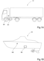
- FIG 1A shows a schematically indicated first vehicle V1 in the form of a truck provided with a battery pack B1.
- Figure 1B shows a schematically indicated second vehicle V2 in the form of a marine vessel provided with a battery pack B2.
- the battery packs B1 and B2 indicated in the figures are high voltage traction batteries comprising multiple energy storage modules, which will be described in detail below.
- the vehicles V1, V2 can also comprise a single energy storage module M1, M2 used for powering auxiliary electrical devices.
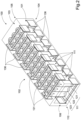
- FIG. 2 shows a schematic diagram of a vehicular energy storage module comprising an outer casing 100 having two parallel first and second side walls 101, 102, parallel upper and lower walls 103, 104, and opposing first and second ends 105, 106.
- the casing 100 is only schematically indicated in Figure 2 , in order to show the enclosed component parts.
- the casing 100 encloses a battery module 110 which battery module includes a plurality of battery cell submodules 111, or battery cell groups.
- each battery cell group 111 includes three battery cells 121, 122, 123 which are electrically interconnected to each other and arranged side-by-side between the side walls 101, 102.
- adjacent battery groups 111 are arranged with their positive poles in opposite directions.
- the battery module 110 comprises multiple heat pipes 131, wherein each heat pipe 131 comprises parallel first and second heat pipe sections 132, 133 connected by intermediate sections 134, 135 at their respective ends (see Fig. 3 ). In this way, the heat pipes form the outline of a rectangle.
- the heat pipes 131 shown in Figures 2 and 3 have a first heat pipe section 132 electrically connected to the positive poles 124 of a first battery cell group 111 and a second heat pipe section 133 electrically connected to the negative poles 125 of an adjacent battery cell group 111. This arrangement allows the first and second heat pipe sections 132, 133 to connect battery cells 121, 122, 123 in each battery cell group 111 in parallel throughout the battery module 110.
- heat pipes 131 are arranged in contact with positive and negative poles of adjacent battery cell groups 111 on opposite sides of the battery module 110, wherein the battery cell groups 111 making up the battery module 110 are connected in series throughout the battery module 110. As can be seen in Figures 2 and 3 , one heat pipe at either end of the lower wall 104 of the battery module 110 will only be in contact with a single battery cell group 111.
- Figure 2 further indicates that opposite intermediate sections 134, 135 of each heat pipe 131 are thermally coupled to a heat sink 136 in a respective side wall, wherein the heat pipe is arranged to channel heat from the battery cells to the casing. Heat is conducted directly into the upper and lower walls by the heat pipes 131 and indirectly into the side walls 101,102 via the heat sinks 136. According to an alternative example, the ends of opposite intermediate sections 134, 135 on two adjacent heat pipe 131 can be thermally coupled to a common heat sink 136.
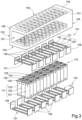
- FIG 3 shows an exploded view of the energy storage module in Figure 2 .
- the heat pipes 131 and opposing end portions of the battery cells 121, 122, 123 are encased within the upper and lower walls 103, 104 of the casing 100 to form an integral part thereof.
- the internal component parts normally integrated in the casing 100 have been removed for clarity reasons.
- the casing 100 comprises two parallel first and second side walls 101, 102, parallel upper and lower walls 103, 104, and opposing first and second ends 105, 106.
- the heat pipes and opposed ends of the battery cells are encased within the upper and lower walls 103, 104 to form an integral part of the casing 100.
- a battery management unit (not shown) for monitoring and controlling the operation of the cells in the battery module can be mounted integrated in one of the walls making up the casing.
- electrical wiring for connecting the module to electrical consumers in the vehicle, or to adjacent modules are preferable integrated in the casing.
- the electrical wiring is connected to external contacts or sockets (not shown) on the outer surface of the casing.
- each battery cell group 111 includes three battery cells 121, 122, 123 arranged side-by-side and where adjacent battery groups 111 are arranged with their positive poles 124 (+) and negative poles 125 (-) arranged alternately in opposite directions.
- the figure further shows an upper set 141 and a lower set 142 of heat pipes 131 arranged on opposite sides of the battery cell assembly in the battery module 110.
- Each heat pipe 131 comprises parallel first and second heat pipe sections 132, 133 connected by intermediate sections 134, 135 at their respective ends. In this way, the sections form a continuous heat pipe having the outline of a rectangle. This arrangement provides a relatively light heat pipe, as opposed to a single solid rectangular body.
- the heat pipes 131 shown in Figure 3 have a first heat pipe section 132 electrically connected to the positive poles 124 of a first battery cell group 111 and a second heat pipe section 133 electrically connected to the negative poles 125 of an adjacent battery cell group 111.
- the respective intermediate sections 134, 135 at opposite ends of each heat pipe 131 are thermally coupled to a heat sink 136, wherein the heat pipe is arranged to channel heat from the battery cells to the side walls of the casing 101, 102.
- each heat sink 136 is thermally connected to the intermediate sections 134, 135 of each heat pipe 131.
- each heat sink 136 can be thermally connected to the ends of intermediate sections 134, 135 of two adjacent heat pipes.
- one heat sink 136 at either end of the upper wall 103 of the battery module 110 will only be thermally coupled to the intermediate section of a single heat pipe 131.
- the heat pipes 131 with their intermediate sections 134, 135 are thermally coupled to passive heat sinks 136 encased within the side walls of the casing.
- the heat sinks 136 shown in these examples are metal plates made from e.g. copper.
- the casing consists of a heat conductive and electrically isolating material.
- a suitable material for this purpose is a potting compound.
- Figure 3 further shows that the casing 100 with its first and second side walls 101, 102, and upper and lower walls (103, 104) form an open conduit or cavity 107 through the first and second ends 105, 106 of the casing.
- This cavity 107 allows a flow of cooling fluid to pass through he casing 100 in order to cool the battery module 110 located therein.
- the casing 100 can be provided with end closures at the first and second ends 105, 106, wherein the end closures can be provided with couplings connected to a source of cooling fluid.
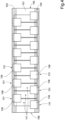
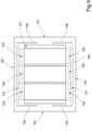
- Figure 4 shows a schematic side view of the energy storage module in Figure 2 .
- Figure 4 indicates how the heat pipes 131 and opposed ends of the battery cells 111 are encased within the upper and lower walls 103, 104 to form an integral part of the casing 100.
- the figure further indicates that the heat sinks 136 are thermally connected to the intermediate section 135 of each heat pipe 131.
- the heat sinks 136 can be thermally connected to the ends of the intermediate section 135 of two adjacent heat pipes 131.
- Figure 5 shows a schematic end view of the energy storage module in Figure 2 .
- Figure 5 Indicates how the heat pipes 131 and opposed positive poles 124 and negative poles 125 of the battery cells 111 in a battery cell group are electrically connected, as well as being encased within the upper and lower walls 103, 104 to form an integral part of the casing 100.
- the figure further indicates how the heat sinks 136 are thermally connected to the intermediate sections 134, 135 of each heat pipe 131.
Landscapes
- Engineering & Computer Science (AREA)
- Chemical & Material Sciences (AREA)
- Chemical Kinetics & Catalysis (AREA)
- Electrochemistry (AREA)
- General Chemical & Material Sciences (AREA)
- Manufacturing & Machinery (AREA)
- Life Sciences & Earth Sciences (AREA)
- Sustainable Development (AREA)
- Sustainable Energy (AREA)
- Power Engineering (AREA)
- Transportation (AREA)
- Mechanical Engineering (AREA)
- Secondary Cells (AREA)
- Battery Mounting, Suspending (AREA)
Claims (12)
- Module de stockage d'énergie pour véhicule, comprenant- un boîtier extérieur (100) ayant deux première et seconde parois latérales parallèles (101, 102), des parois supérieure et inférieure parallèles (103, 104) et de première et seconde extrémités opposées (105, 106) ;- un module de batterie (110) logé à l'intérieur du boîtier (100), le module de batterie comportant :- une pluralité de groupes d'éléments de batterie (111), où chaque groupe d'éléments de batterie comporte au moins deux éléments de batterie (121, 122, 123) qui sont reliés électriquement entre eux et agencés côte à côte entre les parois latérales (101, 102) ;caractérisé en ce que- le module de batterie (110) comprend de multiples caloducs (131), dans lequel chaque caloduc (131) comprend de première et seconde sections de caloduc parallèles (132, 133) reliées par des sections intermédiaires (134, 135) au niveau de leurs extrémités respectives ;- au moins un caloduc a une première section de caloduc (132) connectée électriquement aux pôles positifs (124) d'un premier groupe d'éléments de batterie (111) et une seconde section de caloduc (133) connectée électriquement aux pôles négatifs (125) d'un groupe d'éléments de batterie adjacent (111) ;- des caloducs (131) sont agencés en contact avec des pôles positif et négatif des groupes d'éléments de batterie adjacents (111) sur des côtés opposés du module de batterie (110) ; dans lequel les groupes d'éléments de batterie (111) composant le module de batterie (110) sont connectés en série,- les sections intermédiaires (134, 135) de chaque caloduc sont couplées thermiquement à au moins un dissipateur thermique passif (136) encastré dans une paroi latérale du boîtier, et- le boîtier (100) est ouvert au niveau des première et seconde extrémités (105, 106), dans lequel les première et seconde parois latérales (101, 102), et les parois supérieure et inférieure (103, 104) forment un conduit pour un fluide de refroidissement.
- Module de stockage d'énergie pour véhicule selon la revendication 1,
caractérisé en ce que
l'au moins un caloduc (131) a une forme rectangulaire. - Module de stockage d'énergie pour véhicule selon la revendication 1 ou 2, caractérisé en ce que les première et seconde sections de caloduc (132, 133) et les sections intermédiaires (134, 135) forment un seul caloduc.
- Module de stockage d'énergie pour véhicule selon la revendication 1 ou 2, caractérisé en ce que les première et seconde sections de caloduc (132, 133) sont reliées par des sections intermédiaires (134, 135) comprenant un matériau conducteur de chaleur.
- Module de stockage d'énergie pour véhicule selon l'une des revendications 1 à 4,
caractérisé en ce que des caloducs (131) sont encastrés dans les parois supérieure et inférieure (103, 104) pour former une partie intégrante du boîtier (100). - Module de stockage d'énergie pour véhicule selon l'une des revendications 1 à 4,
caractérisé en ce que des caloducs (131) et des parties d'extrémité opposées des éléments de batterie (121, 122, 123) sont encastrés dans les parois supérieure et inférieure (103, 104) pour former une partie intégrante du boîtier (100). - Module de stockage d'énergie pour véhicule selon l'une quelconque des revendications précédentes,
caractérisé en ce que le dissipateur thermique (136) est relié thermiquement aux sections intermédiaires (134, 135) au niveau d'extrémités opposées de chaque caloduc (131). - Module de stockage d'énergie pour véhicule selon l'une quelconque des revendications précédentes,
caractérisé en ce que le dissipateur thermique (136) est une plaque métallique. - Module de stockage d'énergie pour véhicule selon l'une quelconque des revendications précédentes,
caractérisé en ce que le boîtier (100) est constitué d'un matériau conducteur de chaleur et isolant électrique. - Module de stockage d'énergie pour véhicule selon l'une quelconque des revendications précédentes,
caractérisé en ce que le boîtier (100) est constitué d'un composé d'enrobage. - Bloc-batterie, caractérisé en ce que le bloc-batterie comprend de multiples modules de stockage d'énergie pour véhicule selon la revendication 1.
- Véhicule, caractérisé en ce que le véhicule est équipé d'un bloc-batterie comprenant de multiples modules de stockage d'énergie pour véhicule selon la revendication 1.
Priority Applications (1)
| Application Number | Priority Date | Filing Date | Title |
|---|---|---|---|
| EP24156458.2A EP4360945B1 (fr) | 2020-02-04 | 2020-02-04 | Module de stockage d'énergie de véhicule, bloc-batterie et véhicule |
Applications Claiming Priority (1)
| Application Number | Priority Date | Filing Date | Title |
|---|---|---|---|
| PCT/EP2020/052652 WO2021155906A1 (fr) | 2020-02-04 | 2020-02-04 | Module de stockage d'énergie de vehicule, bloc-batterie et véhicule |
Related Child Applications (2)
| Application Number | Title | Priority Date | Filing Date |
|---|---|---|---|
| EP24156458.2A Division-Into EP4360945B1 (fr) | 2020-02-04 | 2020-02-04 | Module de stockage d'énergie de véhicule, bloc-batterie et véhicule |
| EP24156458.2A Division EP4360945B1 (fr) | 2020-02-04 | 2020-02-04 | Module de stockage d'énergie de véhicule, bloc-batterie et véhicule |
Publications (3)
| Publication Number | Publication Date |
|---|---|
| EP4100277A1 EP4100277A1 (fr) | 2022-12-14 |
| EP4100277C0 EP4100277C0 (fr) | 2024-05-29 |
| EP4100277B1 true EP4100277B1 (fr) | 2024-05-29 |
Family
ID=69500725
Family Applications (2)
| Application Number | Title | Priority Date | Filing Date |
|---|---|---|---|
| EP20703968.6A Active EP4100277B1 (fr) | 2020-02-04 | 2020-02-04 | Module de stockage d'énergie de vehicule, bloc-batterie et véhicule |
| EP24156458.2A Active EP4360945B1 (fr) | 2020-02-04 | 2020-02-04 | Module de stockage d'énergie de véhicule, bloc-batterie et véhicule |
Family Applications After (1)
| Application Number | Title | Priority Date | Filing Date |
|---|---|---|---|
| EP24156458.2A Active EP4360945B1 (fr) | 2020-02-04 | 2020-02-04 | Module de stockage d'énergie de véhicule, bloc-batterie et véhicule |
Country Status (4)
| Country | Link |
|---|---|
| US (1) | US20230065285A1 (fr) |
| EP (2) | EP4100277B1 (fr) |
| CN (1) | CN115003545A (fr) |
| WO (1) | WO2021155906A1 (fr) |
Families Citing this family (4)
| Publication number | Priority date | Publication date | Assignee | Title |
|---|---|---|---|---|
| FR3147243A1 (fr) * | 2023-03-28 | 2024-10-04 | Finx | Engin nautique à propulsion électrique intégrant un châssis comprenant des batteries électriques et/ou au moins un moteur électrique |
| DE102023211123B4 (de) * | 2023-11-10 | 2025-09-11 | Schaeffler Technologies AG & Co. KG | Elektrisches Antriebssystem |
| EP4564531A1 (fr) * | 2023-11-29 | 2025-06-04 | Samsung SDI Co., Ltd. | Système de batterie et unité de transfert de chaleur pour système de batterie |
| GB2638480A (en) * | 2024-02-26 | 2025-08-27 | Mercedes Benz Group Ag | A battery cell arrangement for an electrical storage device |
Citations (2)
| Publication number | Priority date | Publication date | Assignee | Title |
|---|---|---|---|---|
| US20150349389A1 (en) * | 2013-02-18 | 2015-12-03 | Takashi Kobune | Battery Block and Secondary Battery Module |
| US20170279172A1 (en) * | 2016-03-25 | 2017-09-28 | Xing Mobility | Submerged cell modular battery system |
Family Cites Families (13)
| Publication number | Priority date | Publication date | Assignee | Title |
|---|---|---|---|---|
| US6653002B1 (en) * | 1997-05-09 | 2003-11-25 | Ronald J. Parise | Quick charge battery with thermal management |
| KR20110118807A (ko) * | 2010-01-29 | 2011-11-01 | 파나소닉 주식회사 | 전지 모듈 |
| WO2014106094A1 (fr) * | 2012-12-28 | 2014-07-03 | Johnson Controls Technology Company | Modules et éléments de batterie au lithium-ion polymérisés présentant des caractéristiques de gestion de la perméabilité |
| US9490465B2 (en) * | 2013-03-11 | 2016-11-08 | Atieva, Inc. | Z-shaped bus bar for a battery pack |
| US9735414B2 (en) * | 2015-08-11 | 2017-08-15 | Atieva, Inc. | Current distribution system for a battery assembly utilizing non-overlapping bus bars |
| WO2017218218A1 (fr) * | 2016-06-13 | 2017-12-21 | Pure Watercraft, Inc. | Batteries à gestion thermique |
| US10700335B2 (en) * | 2016-09-07 | 2020-06-30 | Thunder Power New Energy Vehicle Development Company Limited | Battery system housing with internal busbar |
| US10541403B2 (en) * | 2016-10-14 | 2020-01-21 | Tiveni Mergeco, Inc. | Cylindrical battery cell configured with insulation component, and battery module containing the same |
| US11611119B2 (en) * | 2017-04-10 | 2023-03-21 | Yun Energy Limited Company | Battery module, battery device, and battery system having thermal management design |
| US11469466B2 (en) * | 2017-05-23 | 2022-10-11 | Aceleron Limited | Battery pack assembly |
| DE102017213470A1 (de) * | 2017-08-03 | 2019-02-07 | Bayerische Motoren Werke Aktiengesellschaft | Batteriemodul und Batteriemodulstapel für ein Kraftfahrzeug |
| DE102017218248A1 (de) * | 2017-10-12 | 2019-04-18 | Volkswagen Aktiengesellschaft | Batteriezellen-Modul, Sekundär-Batterie und Kraftfahrzeug |
| CN110707257B (zh) * | 2019-10-25 | 2022-05-27 | 中铁轨道交通装备有限公司 | 一种具有加热功能的电池箱系统 |
-
2020
- 2020-02-04 EP EP20703968.6A patent/EP4100277B1/fr active Active
- 2020-02-04 WO PCT/EP2020/052652 patent/WO2021155906A1/fr not_active Ceased
- 2020-02-04 CN CN202080094198.8A patent/CN115003545A/zh active Pending
- 2020-02-04 US US17/760,053 patent/US20230065285A1/en active Pending
- 2020-02-04 EP EP24156458.2A patent/EP4360945B1/fr active Active
Patent Citations (2)
| Publication number | Priority date | Publication date | Assignee | Title |
|---|---|---|---|---|
| US20150349389A1 (en) * | 2013-02-18 | 2015-12-03 | Takashi Kobune | Battery Block and Secondary Battery Module |
| US20170279172A1 (en) * | 2016-03-25 | 2017-09-28 | Xing Mobility | Submerged cell modular battery system |
Also Published As
| Publication number | Publication date |
|---|---|
| EP4100277C0 (fr) | 2024-05-29 |
| WO2021155906A1 (fr) | 2021-08-12 |
| CN115003545A (zh) | 2022-09-02 |
| EP4360945B1 (fr) | 2025-09-03 |
| EP4100277A1 (fr) | 2022-12-14 |
| EP4360945A3 (fr) | 2024-08-07 |
| EP4360945A2 (fr) | 2024-05-01 |
| US20230065285A1 (en) | 2023-03-02 |
Similar Documents
| Publication | Publication Date | Title |
|---|---|---|
| US20240213579A1 (en) | Battery pack comprising frame profile having integral refrigerant circuit member | |
| EP3482429B1 (fr) | Système de batterie et véhicule | |
| EP4100277B1 (fr) | Module de stockage d'énergie de vehicule, bloc-batterie et véhicule | |
| EP3346517B1 (fr) | Système de batterie | |
| KR102029407B1 (ko) | 전지 시스템 | |
| EP2337112B1 (fr) | Bloc-batteries et véhicule l'intégrant | |
| EP1805843B1 (fr) | Systeme de refroidissement pour bloc batterie | |
| US11139521B2 (en) | Battery submodule carrier, battery submodule, battery system and vehicle | |
| US20220285755A1 (en) | Top Cooling Type Battery Pack | |
| US5385793A (en) | Thermal management of battery systems | |
| EP3506383B1 (fr) | Module de batterie | |
| EP3319146B1 (fr) | Système de batterie | |
| EP3316391B1 (fr) | Système de batterie, assise de système de batterie et véhicule électrique | |
| EP3309858B1 (fr) | Support de module de batterie, système de batterie et utilisation d'un profilé h modifié comme support de batterie | |
| US10062876B2 (en) | Battery module carrier, battery module, and vehicle with a battery system | |
| US11611120B2 (en) | Battery module, battery pack comprising battery module, and vehicle comprising battery pack | |
| JP2018006313A (ja) | 電池モジュールキャリア、電池モジュール、および電池システムを含む自動車 | |
| US12068467B2 (en) | Battery pack and device including the same | |
| KR102877728B1 (ko) | 배터리 모듈 및 이를 구비하는 배터리 팩 | |
| US20240186617A1 (en) | Battery Module Including Insulating Oil and Battery Pack Including the Same | |
| JPWO2014068922A1 (ja) | 車載用の電源装置及び電源装置を備える車両 | |
| JP2016012389A (ja) | 電源装置及び電源装置を備える車両 | |
| EP3540820B1 (fr) | Bloc-batterie | |
| EP3637536B1 (fr) | Élément de couplage pour un bloc-batterie d'un véhicule | |
| US20230122982A1 (en) | Battery module, a battery pack, an electric vehicle, a bmm carrier, a bmm arrangement and a method for assembling a battery module |
Legal Events
| Date | Code | Title | Description |
|---|---|---|---|
| STAA | Information on the status of an ep patent application or granted ep patent |
Free format text: STATUS: UNKNOWN |
|
| STAA | Information on the status of an ep patent application or granted ep patent |
Free format text: STATUS: THE INTERNATIONAL PUBLICATION HAS BEEN MADE |
|
| PUAI | Public reference made under article 153(3) epc to a published international application that has entered the european phase |
Free format text: ORIGINAL CODE: 0009012 |
|
| STAA | Information on the status of an ep patent application or granted ep patent |
Free format text: STATUS: REQUEST FOR EXAMINATION WAS MADE |
|
| 17P | Request for examination filed |
Effective date: 20220902 |
|
| AK | Designated contracting states |
Kind code of ref document: A1 Designated state(s): AL AT BE BG CH CY CZ DE DK EE ES FI FR GB GR HR HU IE IS IT LI LT LU LV MC MK MT NL NO PL PT RO RS SE SI SK SM TR |
|
| DAV | Request for validation of the european patent (deleted) | ||
| DAX | Request for extension of the european patent (deleted) | ||
| GRAP | Despatch of communication of intention to grant a patent |
Free format text: ORIGINAL CODE: EPIDOSNIGR1 |
|
| STAA | Information on the status of an ep patent application or granted ep patent |
Free format text: STATUS: GRANT OF PATENT IS INTENDED |
|
| INTG | Intention to grant announced |
Effective date: 20231218 |
|
| GRAS | Grant fee paid |
Free format text: ORIGINAL CODE: EPIDOSNIGR3 |
|
| GRAA | (expected) grant |
Free format text: ORIGINAL CODE: 0009210 |
|
| STAA | Information on the status of an ep patent application or granted ep patent |
Free format text: STATUS: THE PATENT HAS BEEN GRANTED |
|
| AK | Designated contracting states |
Kind code of ref document: B1 Designated state(s): AL AT BE BG CH CY CZ DE DK EE ES FI FR GB GR HR HU IE IS IT LI LT LU LV MC MK MT NL NO PL PT RO RS SE SI SK SM TR |
|
| REG | Reference to a national code |
Ref country code: CH Ref legal event code: EP |
|
| REG | Reference to a national code |
Ref country code: IE Ref legal event code: FG4D |
|
| REG | Reference to a national code |
Ref country code: DE Ref legal event code: R096 Ref document number: 602020031604 Country of ref document: DE |
|
| U01 | Request for unitary effect filed |
Effective date: 20240624 |
|
| U07 | Unitary effect registered |
Designated state(s): AT BE BG DE DK EE FI FR IT LT LU LV MT NL PT SE SI Effective date: 20240703 |
|
| PG25 | Lapsed in a contracting state [announced via postgrant information from national office to epo] |
Ref country code: IS Free format text: LAPSE BECAUSE OF FAILURE TO SUBMIT A TRANSLATION OF THE DESCRIPTION OR TO PAY THE FEE WITHIN THE PRESCRIBED TIME-LIMIT Effective date: 20240929 |
|
| PG25 | Lapsed in a contracting state [announced via postgrant information from national office to epo] |
Ref country code: HR Free format text: LAPSE BECAUSE OF FAILURE TO SUBMIT A TRANSLATION OF THE DESCRIPTION OR TO PAY THE FEE WITHIN THE PRESCRIBED TIME-LIMIT Effective date: 20240529 |
|
| PG25 | Lapsed in a contracting state [announced via postgrant information from national office to epo] |
Ref country code: GR Free format text: LAPSE BECAUSE OF FAILURE TO SUBMIT A TRANSLATION OF THE DESCRIPTION OR TO PAY THE FEE WITHIN THE PRESCRIBED TIME-LIMIT Effective date: 20240830 |
|
| PG25 | Lapsed in a contracting state [announced via postgrant information from national office to epo] |
Ref country code: ES Free format text: LAPSE BECAUSE OF FAILURE TO SUBMIT A TRANSLATION OF THE DESCRIPTION OR TO PAY THE FEE WITHIN THE PRESCRIBED TIME-LIMIT Effective date: 20240529 |
|
| PG25 | Lapsed in a contracting state [announced via postgrant information from national office to epo] |
Ref country code: PL Free format text: LAPSE BECAUSE OF FAILURE TO SUBMIT A TRANSLATION OF THE DESCRIPTION OR TO PAY THE FEE WITHIN THE PRESCRIBED TIME-LIMIT Effective date: 20240529 |
|
| PG25 | Lapsed in a contracting state [announced via postgrant information from national office to epo] |
Ref country code: PL Free format text: LAPSE BECAUSE OF FAILURE TO SUBMIT A TRANSLATION OF THE DESCRIPTION OR TO PAY THE FEE WITHIN THE PRESCRIBED TIME-LIMIT Effective date: 20240529 Ref country code: NO Free format text: LAPSE BECAUSE OF FAILURE TO SUBMIT A TRANSLATION OF THE DESCRIPTION OR TO PAY THE FEE WITHIN THE PRESCRIBED TIME-LIMIT Effective date: 20240829 Ref country code: IS Free format text: LAPSE BECAUSE OF FAILURE TO SUBMIT A TRANSLATION OF THE DESCRIPTION OR TO PAY THE FEE WITHIN THE PRESCRIBED TIME-LIMIT Effective date: 20240929 Ref country code: HR Free format text: LAPSE BECAUSE OF FAILURE TO SUBMIT A TRANSLATION OF THE DESCRIPTION OR TO PAY THE FEE WITHIN THE PRESCRIBED TIME-LIMIT Effective date: 20240529 Ref country code: GR Free format text: LAPSE BECAUSE OF FAILURE TO SUBMIT A TRANSLATION OF THE DESCRIPTION OR TO PAY THE FEE WITHIN THE PRESCRIBED TIME-LIMIT Effective date: 20240830 Ref country code: ES Free format text: LAPSE BECAUSE OF FAILURE TO SUBMIT A TRANSLATION OF THE DESCRIPTION OR TO PAY THE FEE WITHIN THE PRESCRIBED TIME-LIMIT Effective date: 20240529 Ref country code: RS Free format text: LAPSE BECAUSE OF FAILURE TO SUBMIT A TRANSLATION OF THE DESCRIPTION OR TO PAY THE FEE WITHIN THE PRESCRIBED TIME-LIMIT Effective date: 20240829 |
|
| PG25 | Lapsed in a contracting state [announced via postgrant information from national office to epo] |
Ref country code: CZ Free format text: LAPSE BECAUSE OF FAILURE TO SUBMIT A TRANSLATION OF THE DESCRIPTION OR TO PAY THE FEE WITHIN THE PRESCRIBED TIME-LIMIT Effective date: 20240529 |
|
| PG25 | Lapsed in a contracting state [announced via postgrant information from national office to epo] |
Ref country code: RO Free format text: LAPSE BECAUSE OF FAILURE TO SUBMIT A TRANSLATION OF THE DESCRIPTION OR TO PAY THE FEE WITHIN THE PRESCRIBED TIME-LIMIT Effective date: 20240529 Ref country code: SK Free format text: LAPSE BECAUSE OF FAILURE TO SUBMIT A TRANSLATION OF THE DESCRIPTION OR TO PAY THE FEE WITHIN THE PRESCRIBED TIME-LIMIT Effective date: 20240529 |
|
| PG25 | Lapsed in a contracting state [announced via postgrant information from national office to epo] |
Ref country code: SM Free format text: LAPSE BECAUSE OF FAILURE TO SUBMIT A TRANSLATION OF THE DESCRIPTION OR TO PAY THE FEE WITHIN THE PRESCRIBED TIME-LIMIT Effective date: 20240529 |
|
| PG25 | Lapsed in a contracting state [announced via postgrant information from national office to epo] |
Ref country code: SM Free format text: LAPSE BECAUSE OF FAILURE TO SUBMIT A TRANSLATION OF THE DESCRIPTION OR TO PAY THE FEE WITHIN THE PRESCRIBED TIME-LIMIT Effective date: 20240529 Ref country code: SK Free format text: LAPSE BECAUSE OF FAILURE TO SUBMIT A TRANSLATION OF THE DESCRIPTION OR TO PAY THE FEE WITHIN THE PRESCRIBED TIME-LIMIT Effective date: 20240529 Ref country code: RO Free format text: LAPSE BECAUSE OF FAILURE TO SUBMIT A TRANSLATION OF THE DESCRIPTION OR TO PAY THE FEE WITHIN THE PRESCRIBED TIME-LIMIT Effective date: 20240529 Ref country code: CZ Free format text: LAPSE BECAUSE OF FAILURE TO SUBMIT A TRANSLATION OF THE DESCRIPTION OR TO PAY THE FEE WITHIN THE PRESCRIBED TIME-LIMIT Effective date: 20240529 |
|
| U20 | Renewal fee for the european patent with unitary effect paid |
Year of fee payment: 6 Effective date: 20250224 |
|
| PLBE | No opposition filed within time limit |
Free format text: ORIGINAL CODE: 0009261 |
|
| STAA | Information on the status of an ep patent application or granted ep patent |
Free format text: STATUS: NO OPPOSITION FILED WITHIN TIME LIMIT |
|
| 26N | No opposition filed |
Effective date: 20250303 |
|
| PG25 | Lapsed in a contracting state [announced via postgrant information from national office to epo] |
Ref country code: MC Free format text: LAPSE BECAUSE OF FAILURE TO SUBMIT A TRANSLATION OF THE DESCRIPTION OR TO PAY THE FEE WITHIN THE PRESCRIBED TIME-LIMIT Effective date: 20240529 |
|
| REG | Reference to a national code |
Ref country code: CH Ref legal event code: PL |
|
| PG25 | Lapsed in a contracting state [announced via postgrant information from national office to epo] |
Ref country code: CH Free format text: LAPSE BECAUSE OF NON-PAYMENT OF DUE FEES Effective date: 20250228 |
|
| GBPC | Gb: european patent ceased through non-payment of renewal fee |
Effective date: 20250204 |
|
| PG25 | Lapsed in a contracting state [announced via postgrant information from national office to epo] |
Ref country code: GB Free format text: LAPSE BECAUSE OF NON-PAYMENT OF DUE FEES Effective date: 20250204 |
|
| PG25 | Lapsed in a contracting state [announced via postgrant information from national office to epo] |
Ref country code: IE Free format text: LAPSE BECAUSE OF NON-PAYMENT OF DUE FEES Effective date: 20250204 |
|
| U20 | Renewal fee for the european patent with unitary effect paid |
Year of fee payment: 7 Effective date: 20260224 |