EP4100357B1 - Vorrichtung zum öffnen einer weinflasche oder dergleichen mit einer heissklammer - Google Patents
Vorrichtung zum öffnen einer weinflasche oder dergleichen mit einer heissklammer Download PDFInfo
- Publication number
- EP4100357B1 EP4100357B1 EP21707350.1A EP21707350A EP4100357B1 EP 4100357 B1 EP4100357 B1 EP 4100357B1 EP 21707350 A EP21707350 A EP 21707350A EP 4100357 B1 EP4100357 B1 EP 4100357B1
- Authority
- EP
- European Patent Office
- Prior art keywords
- bracket
- casing
- clamp
- base
- heating means
- Prior art date
- Legal status (The legal status is an assumption and is not a legal conclusion. Google has not performed a legal analysis and makes no representation as to the accuracy of the status listed.)
- Active
Links
Images


Classifications
-
- B—PERFORMING OPERATIONS; TRANSPORTING
- B67—OPENING, CLOSING OR CLEANING BOTTLES, JARS OR SIMILAR CONTAINERS; LIQUID HANDLING
- B67B—APPLYING CLOSURE MEMBERS TO BOTTLES JARS, OR SIMILAR CONTAINERS; OPENING CLOSED CONTAINERS
- B67B7/00—Hand- or power-operated devices for opening closed containers
- B67B7/02—Hand- or power-operated devices for opening closed containers for removing stoppers
-
- B—PERFORMING OPERATIONS; TRANSPORTING
- B67—OPENING, CLOSING OR CLEANING BOTTLES, JARS OR SIMILAR CONTAINERS; LIQUID HANDLING
- B67B—APPLYING CLOSURE MEMBERS TO BOTTLES JARS, OR SIMILAR CONTAINERS; OPENING CLOSED CONTAINERS
- B67B7/00—Hand- or power-operated devices for opening closed containers
- B67B7/92—Hand- or power-operated devices for opening closed containers by breaking, e.g. for ampoules
Definitions
- the present invention relates to the field of wine and more particularly a device for opening bottles of natural sweet wines such as port for example.
- the cork stoppers closing port bottles disintegrate over time due to the alcohol level and the sugar content of the port in particular, the lower part of the cork stopper generally being the most degraded due to the fact that it is partly in direct contact with the port.
- the process consists of heating the jaws of the port tongs on the embers of a fireplace or the like then positioning the white-hot jaws around the neck of the port bottle under the lower end of the cork, then removing the jaws hot water from the neck and place a cloth soaked in cold water on the neck in the area heated by the jaws.
- the thermal shock causes the glass to break and the upper end of the neck of the bottle can be removed with the cork and the port can then be served after decanting if necessary.
- One of the aims of the invention is therefore to remedy these drawbacks by proposing a device for opening a bottle of wine with hot pliers of a simple and inexpensive design, easy to use and providing good security. for the user.
- a device for opening a bottle of wine comprising a clamp consisting of two arms articulated around an axis, each arm comprising at a first end a handle or a ring and at its opposite end a jaw of semi-annular or semi-cylindrical shape, the radius of curvature of each jaw being substantially equal to the radius of curvature of the wine bottle; said device is remarkable in that it comprises at least one base, heating means positioned on said base and a bracket secured to the base and comprising means for retaining the pliers such that the jaws of the latter extend to the right of the heating means.
- said bracket comprises a vertical lower part, i.e. extending substantially perpendicular to said base, and an inclined upper part.
- the upper part of the stem forms an angle of between 100° and 130° with the lower part of said stem and, preferably, the upper part of the stem forms an angle of 115° with the lower part of said stem .
- the distal end of the stem ie the upper end of the upper part of said stem, is folded upwards at an angle of approximately 90° to form a so-called retaining tab provided with at least one slot capable of receiving the arms of the pliers.
- the upper part of the stem includes at least one cradle in which the arms of the clamp are supported.
- the heating means consist of at least one electrical heating resistance coupled to a thermostat or a rheostat, said electrical heating resistance being in contact with the jaws of the pliers when the latter is supported by the bracket.
- the heating means consist of at least one gas bottle provided with a burner and a gas flow adjustment dial, said gas bottle extending into a casing whose lower end is open and rests on the base and the upper end of which is provided with an upper cover provided with an opening for the passage of the burner.
- the casing has a cylindrical shape.
- the upper cover is made up of two half-discs, each half-disc comprising a semi-circular recess in the central part of the rectilinear edge and a curved tab secured to the curvilinear edge and capable of bearing on the upper edge of the housing.
- the casing comprises, in its lower part, a crown secured to the interior wall of said casing on which a circular plate rests, said plate being able to receive the gas bottle .
- the device comprises a remote control means of the gas flow adjustment wheel, said remote control means consisting of a rod extending through a hole made in the casing and comprising at its free ends a wheel and a flat head respectively, said flat head being able to cooperate with a slot made in the gas flow adjustment wheel.
- the device according to the invention is particularly suitable for opening old port bottles whose cork is damaged; however, it is obvious that the device according to the invention could also be used not only for opening bottles of all types of natural sweet wines which encounters the same type of degradation of their cork stoppers but also for the opening of any type of wine bottle whether the cork is degraded or not without departing from the scope of the invention.
- Said base 6 consists of a substantially square horizontal metal plate provided with four feet 9 positioned at the four corners of the metal plate on its underside.
- Said feet 9 may advantageously consist of feet made of silicone or synthetic or natural elastomer in order to prevent said base 6 from sliding on the support, such as a table for example, on which it will be positioned.
- the pliers 1 could have a different shape such as a scissor shape, i.e. with rings in place of the handles 4 and/or with semi-cylindrical jaws 5 in place of the semi-cylindrical jaws 4 -annular for example without departing from the scope of the invention.
- said bracket 8 comprises a vertical lower part 8a, ie extending substantially perpendicular to said base 6, and an inclined upper part 8b.
- Said bracket 8 is, for example, obtained in a metal bar whose lower end is welded in the central part of one of the edges of the base 6 and whose middle part is folded to form the lower parts 8a and upper 8b.
- Said upper part 8b of the bracket 8 forms an angle of between 100° and 130° with the lower part 8a of said bracket 8, and, preferably, an angle of 115° with the lower part 8a of said bracket 8.
- the distal end of the bracket 8, ie the upper end of the upper part 8b of said bracket 8, is folded upwards at an angle of approximately 90° to form a so-called retaining tab 10 provided with at less a slot 11 capable of receiving the arms 2 of the clamp 1, the handles 4 of the clamp 4 bearing on the upper face of the tab 10.
- said upper part 8b of the bracket 8 comprises at least one cradle 12 in which the arms 2 of the clamp 1 are supported.
- the heating means 7 consist of at least one gas bottle 13 provided with a burner 14 and a wheel 15 for adjusting the gas flow, said gas bottle 13 extending into a casing 16 of which the the lower end is open and rests on the base 6 and the upper end of which is provided with an upper cover 17 provided with an opening 18 for the passage of the burner 14.
- the casing 16 has a cylindrical shape; however, it goes without saying that it can have any shape as long as it is capable of receiving a gas bottle, without departing from the scope of the invention.
- the casing 16 comprises, in its lower part, a crown 19 secured to the interior wall of said casing 16 on which rests a removable circular plate 20, said plate 20 being capable of receiving the gas bottle 13.
- the casing 16 allows two different sizes of gas bottle 13 to be received.
- the plate 20 is removed and the gas bottle rests directly on the base 6 and, for the smallest size of gas bottle 13, the plate 20 is positioned on the crown 19 and the gas bottle rests on said plate 20.
- the device according to the invention comprises a remote control means 21 of the wheel 15 for adjusting the gas flow, said remote control means 21 consisting of a rod 22 extending through a hole 23 made in the casing 16 and comprising at its free ends a wheel 24 and a flat head 25 respectively, said flat head 25 being able to cooperate with a slot 26 made in the wheel 15 for adjusting the gas flow.
- the device comprises in the same manner as previously a clamp 1 consisting of two arms 2 articulated around an axis 3, each arm 2 comprising at a first end a handle 4 and at its opposite end a jaw 5 of semi-annular shape , the radius of curvature of each jaw 5 being substantially equal to the radius of curvature of the wine bottle, not shown in the figures, a base 6, heating means 7 positioned on said base 6 and a bracket 8 integral with said base 6 and comprising means for retaining the clamp 1 such that the jaws 5 of said clamp 1 extend to the right of the heating means 7.
- Said base 6 consists of a substantially square horizontal metal plate provided with four feet 9 positioned at the four corners of the metal plate on its underside.
- said bracket 8 comprises a vertical lower part 8a and an inclined upper part 8b. Its lower end is welded in the central part of one of the edges of the base 6 and the middle part is folded to form the lower parts 8a and upper 8b. Said upper part 8b of the bracket 8 forms an angle of between 100° and 130° with the lower part 8a of said bracket 8, and, preferably, an angle of 115°.
- the distal end of the bracket 8, i.e. the upper end of the upper part 8b of said bracket 8 is folded upwards at an angle of approximately 90° to form a so-called retaining tab 10 provided with at least one bayonet slot 11 capable of receiving the arms 2 of the pliers 1, the handles 4 of the pliers 4 bearing on the upper face of the tab 10.
- said upper part 8b of the bracket 8 comprises at least one cradle 12 in which the arms 2 of the clamp 1 are supported.
- the heating means 7 consist of at least one gas bottle 13 provided with a burner 14 and a wheel 15 for adjusting the gas flow, said gas bottle 13 extending into a cylindrical casing 16 of which the lower end is open and rests on the base 6 and the upper end of which is provided with an upper cover 17 provided with an opening 18 for the passage of the burner 14.
- the casing 16 also comprises, in its lower part, a crown 19 secured to the interior wall of said casing 16 on which rests a removable circular plate 20, said plate 20 being capable of receiving the gas bottle 13.
- the casing 16 makes it possible to receive two different sizes of gas bottle 13.
- the device according to the invention also comprises a remote control means 21 of the wheel 15 for adjusting the gas flow, as shown on the figures 3 to 5 , said remote control means 21 consisting of a rod 22 extending through a hole 23 made in the casing 16 and comprising at its free ends a wheel 24 and a flat head 25 respectively, said flat head 25 being capable of cooperate with a slot 26 made in the wheel 15 for adjusting the gas flow.
- the device differs from that described previously by the fact that the upper cover 17 is made up of two half-discs 17a, 17ab, each half-disc 17a, 17b comprising a semicircular recess 18a and 18b respectively in the central part of the rectilinear edge and a curved tab 19a and 19b respectively secured to the curvilinear edge and capable of bearing on the upper edge of the casing 16.
- the device according to the invention comprises heating means consisting of at least one electrical heating resistance coupled to a thermostat or a rheostat, said electrical resistance heating being in contact, or extending close to, the jaws of the pliers when the latter is supported by the bracket.
- the electric heating resistance may be covered with a ceramic material and have a circular shape.
- the heating means may comprise two electrical heating resistors covered with ceramic and articulated around an axis so as to pivot from an open position where the electrical heating resistors extend on either side of the jaws of the pliers to a closed position where the electrical heating resistors cap the jaws of the pliers.
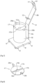
- the device according to the invention comprises a second clamp 27 consisting of two arms 28 articulated around an axis 29, each arm 28 comprising at a first end a ring 30 and at its opposite end a jaw 31 of semi-annular shape, the radius of curvature of each jaw 31 being substantially equal to the radius of curvature of the neck of the wine bottle.
- the concave face of each jaw 31 comprises one or more thermal accumulation elements 32. These thermal accumulation elements 32 can be obtained in stone such as sandstone or granite for example.
- these thermal storage elements are obtained in at least one solid material having a thermal conductivity greater than or equal to 5 Wm-1.K-1 and a density greater than or equal to 2000 kg/m3.
- the thermal accumulation elements 32 are obtained in a single-piece natural stone or in powder form, compacted or not.
- the thermal storage elements 32 are obtained in steatite and/or cordierite and/or feolite. Said clamp 1 is thus placed in a tray of ice or in a refrigerator or freezer before being used.
Landscapes
- Engineering & Computer Science (AREA)
- Mechanical Engineering (AREA)
- Devices For Opening Bottles Or Cans (AREA)
- Table Equipment (AREA)
Claims (12)
- Vorrichtung zum Öffnen einer Weinflasche, umfassend eine Zange (1) bestehend aus zwei um eine Achse (3) gelenkigen Armen (2), wobei jeder Arm (2) an einem ersten Ende einen Griff (4) oder einen Ring umfasst, und an seinem entgegengesetzten Ende eine Spannbacke (5) in einer halbringförmigen oder halbzylindrischen Form, wobei der Krümmungsradius einer jeden Spannbacke (5) im Wesentlichen gleich dem Krümmungsradius des Halses der Weinflasche ist, wobei die Vorrichtung mindestens einen Sockel (6) und Heizmittel (7) umfasst, dadurch gekennzeichnet, dass die Heizmittel (7) auf dem Sockel (6) positioniert sind, und dadurch, dass die Vorrichtung weiter eine Stütze (8) umfasst, die fest mit dem Sockel (6) verbunden ist, und Mittel zum Halten der Zange (1) umfasst, sodass sich die Spannbacken (5) dieser letzteren auf Höhe der Heizmittel (7) erstrecken.
- Vorrichtung nach Anspruch 1, dadurch gekennzeichnet, dass die Stütze (8) einen vertikalen unteren Teil (8a), der sich z.B. im Wesentlichen senkrecht zum Sockel (6) erstreckt, und einen geneigten oberen Teil (8b) beinhaltet.
- Vorrichtung nach Anspruch 2, dadurch gekennzeichnet, dass der obere Teil (8b) der Stütze (8) einen Winkel, der zwischen 100° und 130° liegt, mit dem unteren Teil (8a) der Stütze (8) bildet.
- Vorrichtung nach Anspruch 3, dadurch gekennzeichnet, dass der obere Teil (8b) der Stütze (8) einen Winkel von 115° mit dem unteren Teil (8a) der Stütze (8) bildet.
- Vorrichtung nach einem der Ansprüche 1 bis 4, dadurch gekennzeichnet, dass das distale Ende der Stütze (8), z.B. das obere Ede des oberen Teils (8b) der Stütze (8) entsprechend einem Winkel von etwa 90° nach oben geknickt ist, um eine sogenannte Haltelasche (10) zu bilden, die mit mindestens einem Schlitz (11) versehen ist, der imstande ist, den Arm (2) der Zange (1) aufzunehmen.
- Vorrichtung nach einem der Ansprüche 1 bis 5, dadurch gekennzeichnet, dass der obere Teil (8b) der Stütze (8) mindestens ein Traggestell (12) beinhaltet, in das sich die Arme (2) der Zange (1) anlegen.
- Vorrichtung nach einem der Ansprüche 1 bis 6, dadurch gekennzeichnet, dass die Heizmittel (7) aus mindestens einem elektrischen Heizwiderstand bestehen, der mit einem Thermostat oder einem Rheostat gekoppelt ist, wobei der elektrische Heizwiderstand in Kontakt mit den Spannbacken (5) der Zange (1) ist, wenn letztere von der Stütze (8) getragen wird.
- Vorrichtung nach einem der Ansprüche 1 bis 6, dadurch gekennzeichnet, dass die Heizmittel (7) aus mindestens einer Gasflasche (13) bestehen, die mit einem Brenner (14) und mit einem Rändelrad (15) zum Einstellen des Gasdurchsatzes versehen ist, wobei sich die Gasflasche (13) in einem Gehäuse (16) erstreckt, dessen unteres Ende offen ist, und sich an den Sockel (6) anlegt, und dessen oberes Ende mit einer oberen Abdeckung (17) versehen ist, die mit einer Öffnung (18) für den Durchlass des Brenners (14) versehen ist.
- Vorrichtung nach Anspruch 8, dadurch gekennzeichnet, dass das Gehäuse (16) eine zylindrische Form aufweist.
- Vorrichtung nach Anspruch 9, dadurch gekennzeichnet, dass die obere Abdeckung (17) aus zwei Halbscheiben (17a, 17b) besteht, wobei jede Halbscheibe eine halbringförmige Aussparung (18, 18b) in dem mittleren Teil des geradlinigen Randes, und eine umgebogene Lasche (26a, 26b) umfasst, die fest mit dem gekrümmten Rand verbunden ist, und imstande ist, sich an den oberen Rand des Gehäuses (16) anzulegen.
- Vorrichtung nach einem der Ansprüche 9 oder 10, dadurch gekennzeichnet, dass das Gehäuse (16) in seinem unteren Teil einen Kranz (19) beinhaltet, der fest mit der Innenwand des Gehäuses (16) verbunden ist, an den sich eine kreisförmige Platte (20) anlegt, wobei die Platte (20) imstande ist, die Gasflasche (13) aufzunehmen.
- Vorrichtung nach einem der Ansprüche 8 bis 11, dadurch gekennzeichnet, dass sie ein ausgelagertes Steuerungsmittel (21) für das Rändelrad (15) zum Einstellen des Gasdurchsatzes beinhaltet, wobei das ausgelagerte Steuerungsmittel (21) aus einem Stift (22) besteht, der sich durch ein Loch (23) hindurch erstreckt, das in das Gehäuse (16) eingearbeitet ist, und an seinen freien Enden jeweils ein Rändelrad (24) und einen flachen Kopf (25) umfasst, wobei der flache Kopf (25) imstande ist, mit einem Schlitz (26) zusammenzuwirken, der in das Rändelrad (15) zum Einstellen des Gasdurchsatzes eingearbeitet ist.
Applications Claiming Priority (2)
| Application Number | Priority Date | Filing Date | Title |
|---|---|---|---|
| FR2001217A FR3107049B1 (fr) | 2020-02-07 | 2020-02-07 | Dispositif pour l’ouverture d’une bouteille de vin ou similaire avec une pince chaude |
| PCT/FR2021/050206 WO2021156572A1 (fr) | 2020-02-07 | 2021-02-04 | Dispositif pour l'ouverture d'une bouteille de vin ou similaire avec une pince chaude |
Publications (3)
| Publication Number | Publication Date |
|---|---|
| EP4100357A1 EP4100357A1 (de) | 2022-12-14 |
| EP4100357C0 EP4100357C0 (de) | 2023-11-22 |
| EP4100357B1 true EP4100357B1 (de) | 2023-11-22 |
Family
ID=72178603
Family Applications (1)
| Application Number | Title | Priority Date | Filing Date |
|---|---|---|---|
| EP21707350.1A Active EP4100357B1 (de) | 2020-02-07 | 2021-02-04 | Vorrichtung zum öffnen einer weinflasche oder dergleichen mit einer heissklammer |
Country Status (3)
| Country | Link |
|---|---|
| EP (1) | EP4100357B1 (de) |
| FR (1) | FR3107049B1 (de) |
| WO (1) | WO2021156572A1 (de) |
-
2020
- 2020-02-07 FR FR2001217A patent/FR3107049B1/fr active Active
-
2021
- 2021-02-04 EP EP21707350.1A patent/EP4100357B1/de active Active
- 2021-02-04 WO PCT/FR2021/050206 patent/WO2021156572A1/fr not_active Ceased
Also Published As
| Publication number | Publication date |
|---|---|
| FR3107049B1 (fr) | 2022-02-25 |
| WO2021156572A1 (fr) | 2021-08-12 |
| FR3107049A1 (fr) | 2021-08-13 |
| EP4100357C0 (de) | 2023-11-22 |
| EP4100357A1 (de) | 2022-12-14 |
Similar Documents
| Publication | Publication Date | Title |
|---|---|---|
| EP0091634B1 (de) | Haushaltskaffeemaschine | |
| EP0926974B1 (de) | Brühgetränkevorrichtung | |
| EP1151707A1 (de) | Vorrichtung zum Extrahieren einer Substanz mit einem mobilen Teil | |
| FR2639032A1 (fr) | Recipient comportant un couvercle a liberation de pression | |
| BE1010040A5 (fr) | Dispositif de blocage pour bouteilles et son utilisation. | |
| EP1509735B1 (de) | Vorrichtung zum regeln der temperatur einer flüssigkeit, insbesondere wein | |
| EP4100357B1 (de) | Vorrichtung zum öffnen einer weinflasche oder dergleichen mit einer heissklammer | |
| EP1566124A1 (de) | Verschlussdeckel für ein Behältnis von einem Haushaltsgerät zur Nahrungszubereitung, insbesondere einem Mixer | |
| FR2630316A1 (fr) | Dispositif destine a l'ouverture des coquillages et plus particulierement des huitres | |
| EP1773161B1 (de) | Giessbehälter und brühvorrichtung hierfür | |
| EP3533361B1 (de) | Behälter, der mit einem deckel mit schüttabdichtung mit bistabiler steuerschaltung ausgestattet ist | |
| WO2012007649A1 (fr) | Tire-bouchon à double levier | |
| EP3708038B1 (de) | Maschine zur herstellung von aufgussgetränken, die mit einem drehbaren filterkorb ausgestattet ist | |
| EP0802759A1 (de) | Kochgeschirr mit einem griff und mitteln zum halten eines geräts | |
| FR2917730A1 (fr) | Robinet pour distribuer les aliments contenus dans un recipient et appareil electromenager de preparation culinaire muni d'un tel robinet | |
| FR3111344A1 (fr) | Dispositif pour l’ouverture d’une bouteille de vin ou similaire avec une pince chaude | |
| FR2660737A3 (fr) | Moyen de support d'une broche dans un four electrique combine micro-ondes et resistance chauffante. | |
| FR2817135A1 (fr) | Support de recipient pour la degustation de boissons | |
| EP2291506B1 (de) | Verfahren zur entfernung von ablagerungen aus schaumweinen | |
| EP3937738B1 (de) | Maschine zur herstellung von brühgetränken mit aufhebbarem filterkorb | |
| FR2770606A1 (fr) | Robinet de distribution de liquide | |
| WO1998012951A1 (fr) | Ensemble ouvre-huître securitaire | |
| FR3114806A1 (fr) | Dispositif de maintien d'un robinet de soutirage d'un conteneur | |
| FR2670755A1 (fr) | Recipient distributeur de matieres liquides ou cremeuses. | |
| FR2774977A1 (fr) | Appareil pour l'ouverture d'un recipient comportant un couvercle serti |
Legal Events
| Date | Code | Title | Description |
|---|---|---|---|
| STAA | Information on the status of an ep patent application or granted ep patent |
Free format text: STATUS: UNKNOWN |
|
| STAA | Information on the status of an ep patent application or granted ep patent |
Free format text: STATUS: THE INTERNATIONAL PUBLICATION HAS BEEN MADE |
|
| PUAI | Public reference made under article 153(3) epc to a published international application that has entered the european phase |
Free format text: ORIGINAL CODE: 0009012 |
|
| STAA | Information on the status of an ep patent application or granted ep patent |
Free format text: STATUS: REQUEST FOR EXAMINATION WAS MADE |
|
| 17P | Request for examination filed |
Effective date: 20220901 |
|
| AK | Designated contracting states |
Kind code of ref document: A1 Designated state(s): AL AT BE BG CH CY CZ DE DK EE ES FI FR GB GR HR HU IE IS IT LI LT LU LV MC MK MT NL NO PL PT RO RS SE SI SK SM TR |
|
| DAV | Request for validation of the european patent (deleted) | ||
| DAX | Request for extension of the european patent (deleted) | ||
| GRAP | Despatch of communication of intention to grant a patent |
Free format text: ORIGINAL CODE: EPIDOSNIGR1 |
|
| STAA | Information on the status of an ep patent application or granted ep patent |
Free format text: STATUS: GRANT OF PATENT IS INTENDED |
|
| INTG | Intention to grant announced |
Effective date: 20230614 |
|
| GRAS | Grant fee paid |
Free format text: ORIGINAL CODE: EPIDOSNIGR3 |
|
| GRAA | (expected) grant |
Free format text: ORIGINAL CODE: 0009210 |
|
| STAA | Information on the status of an ep patent application or granted ep patent |
Free format text: STATUS: THE PATENT HAS BEEN GRANTED |
|
| AK | Designated contracting states |
Kind code of ref document: B1 Designated state(s): AL AT BE BG CH CY CZ DE DK EE ES FI FR GB GR HR HU IE IS IT LI LT LU LV MC MK MT NL NO PL PT RO RS SE SI SK SM TR |
|
| REG | Reference to a national code |
Ref country code: GB Ref legal event code: FG4D Free format text: NOT ENGLISH |
|
| REG | Reference to a national code |
Ref country code: DE Ref legal event code: R081 Ref document number: 602021007072 Country of ref document: DE Owner name: HARO, GUILLAUME, FR Free format text: FORMER OWNER: HARO, GUILLAUME, PARIS, FR |
|
| REG | Reference to a national code |
Ref country code: CH Ref legal event code: PK Free format text: RECTIFICATIONS Ref country code: CH Ref legal event code: EP |
|
| REG | Reference to a national code |
Ref country code: DE Ref legal event code: R096 Ref document number: 602021007072 Country of ref document: DE |
|
| RAP4 | Party data changed (patent owner data changed or rights of a patent transferred) |
Owner name: HARO, GUILLAUME |
|
| REG | Reference to a national code |
Ref country code: IE Ref legal event code: FG4D Free format text: LANGUAGE OF EP DOCUMENT: FRENCH |
|
| RIN2 | Information on inventor provided after grant (corrected) |
Inventor name: HARO, GUILLAUME |
|
| U01 | Request for unitary effect filed |
Effective date: 20231215 |
|
| U07 | Unitary effect registered |
Designated state(s): AT BE BG DE DK EE FI FR IT LT LU LV MT NL PT SE SI Effective date: 20231221 |
|
| U20 | Renewal fee for the european patent with unitary effect paid |
Year of fee payment: 4 Effective date: 20240216 |
|
| PG25 | Lapsed in a contracting state [announced via postgrant information from national office to epo] |
Ref country code: GR Free format text: LAPSE BECAUSE OF FAILURE TO SUBMIT A TRANSLATION OF THE DESCRIPTION OR TO PAY THE FEE WITHIN THE PRESCRIBED TIME-LIMIT Effective date: 20240223 |
|
| PG25 | Lapsed in a contracting state [announced via postgrant information from national office to epo] |
Ref country code: IS Free format text: LAPSE BECAUSE OF FAILURE TO SUBMIT A TRANSLATION OF THE DESCRIPTION OR TO PAY THE FEE WITHIN THE PRESCRIBED TIME-LIMIT Effective date: 20240322 |
|
| PG25 | Lapsed in a contracting state [announced via postgrant information from national office to epo] |
Ref country code: ES Free format text: LAPSE BECAUSE OF FAILURE TO SUBMIT A TRANSLATION OF THE DESCRIPTION OR TO PAY THE FEE WITHIN THE PRESCRIBED TIME-LIMIT Effective date: 20231122 |
|
| PG25 | Lapsed in a contracting state [announced via postgrant information from national office to epo] |
Ref country code: IS Free format text: LAPSE BECAUSE OF FAILURE TO SUBMIT A TRANSLATION OF THE DESCRIPTION OR TO PAY THE FEE WITHIN THE PRESCRIBED TIME-LIMIT Effective date: 20240322 Ref country code: GR Free format text: LAPSE BECAUSE OF FAILURE TO SUBMIT A TRANSLATION OF THE DESCRIPTION OR TO PAY THE FEE WITHIN THE PRESCRIBED TIME-LIMIT Effective date: 20240223 Ref country code: ES Free format text: LAPSE BECAUSE OF FAILURE TO SUBMIT A TRANSLATION OF THE DESCRIPTION OR TO PAY THE FEE WITHIN THE PRESCRIBED TIME-LIMIT Effective date: 20231122 |
|
| PG25 | Lapsed in a contracting state [announced via postgrant information from national office to epo] |
Ref country code: RS Free format text: LAPSE BECAUSE OF FAILURE TO SUBMIT A TRANSLATION OF THE DESCRIPTION OR TO PAY THE FEE WITHIN THE PRESCRIBED TIME-LIMIT Effective date: 20231122 Ref country code: PL Free format text: LAPSE BECAUSE OF FAILURE TO SUBMIT A TRANSLATION OF THE DESCRIPTION OR TO PAY THE FEE WITHIN THE PRESCRIBED TIME-LIMIT Effective date: 20231122 Ref country code: NO Free format text: LAPSE BECAUSE OF FAILURE TO SUBMIT A TRANSLATION OF THE DESCRIPTION OR TO PAY THE FEE WITHIN THE PRESCRIBED TIME-LIMIT Effective date: 20240222 Ref country code: HR Free format text: LAPSE BECAUSE OF FAILURE TO SUBMIT A TRANSLATION OF THE DESCRIPTION OR TO PAY THE FEE WITHIN THE PRESCRIBED TIME-LIMIT Effective date: 20231122 |
|
| PG25 | Lapsed in a contracting state [announced via postgrant information from national office to epo] |
Ref country code: CZ Free format text: LAPSE BECAUSE OF FAILURE TO SUBMIT A TRANSLATION OF THE DESCRIPTION OR TO PAY THE FEE WITHIN THE PRESCRIBED TIME-LIMIT Effective date: 20231122 |
|
| PG25 | Lapsed in a contracting state [announced via postgrant information from national office to epo] |
Ref country code: SK Free format text: LAPSE BECAUSE OF FAILURE TO SUBMIT A TRANSLATION OF THE DESCRIPTION OR TO PAY THE FEE WITHIN THE PRESCRIBED TIME-LIMIT Effective date: 20231122 |
|
| PG25 | Lapsed in a contracting state [announced via postgrant information from national office to epo] |
Ref country code: SM Free format text: LAPSE BECAUSE OF FAILURE TO SUBMIT A TRANSLATION OF THE DESCRIPTION OR TO PAY THE FEE WITHIN THE PRESCRIBED TIME-LIMIT Effective date: 20231122 Ref country code: SK Free format text: LAPSE BECAUSE OF FAILURE TO SUBMIT A TRANSLATION OF THE DESCRIPTION OR TO PAY THE FEE WITHIN THE PRESCRIBED TIME-LIMIT Effective date: 20231122 Ref country code: RO Free format text: LAPSE BECAUSE OF FAILURE TO SUBMIT A TRANSLATION OF THE DESCRIPTION OR TO PAY THE FEE WITHIN THE PRESCRIBED TIME-LIMIT Effective date: 20231122 Ref country code: CZ Free format text: LAPSE BECAUSE OF FAILURE TO SUBMIT A TRANSLATION OF THE DESCRIPTION OR TO PAY THE FEE WITHIN THE PRESCRIBED TIME-LIMIT Effective date: 20231122 |
|
| REG | Reference to a national code |
Ref country code: DE Ref legal event code: R097 Ref document number: 602021007072 Country of ref document: DE |
|
| PLBE | No opposition filed within time limit |
Free format text: ORIGINAL CODE: 0009261 |
|
| STAA | Information on the status of an ep patent application or granted ep patent |
Free format text: STATUS: NO OPPOSITION FILED WITHIN TIME LIMIT |
|
| PG25 | Lapsed in a contracting state [announced via postgrant information from national office to epo] |
Ref country code: MC Free format text: LAPSE BECAUSE OF FAILURE TO SUBMIT A TRANSLATION OF THE DESCRIPTION OR TO PAY THE FEE WITHIN THE PRESCRIBED TIME-LIMIT Effective date: 20231122 |
|
| 26N | No opposition filed |
Effective date: 20240823 |
|
| PG25 | Lapsed in a contracting state [announced via postgrant information from national office to epo] |
Ref country code: IE Free format text: LAPSE BECAUSE OF NON-PAYMENT OF DUE FEES Effective date: 20240204 |
|
| PG25 | Lapsed in a contracting state [announced via postgrant information from national office to epo] |
Ref country code: IE Free format text: LAPSE BECAUSE OF NON-PAYMENT OF DUE FEES Effective date: 20240204 |
|
| U20 | Renewal fee for the european patent with unitary effect paid |
Year of fee payment: 5 Effective date: 20250131 |
|
| PG25 | Lapsed in a contracting state [announced via postgrant information from national office to epo] |
Ref country code: CY Free format text: LAPSE BECAUSE OF FAILURE TO SUBMIT A TRANSLATION OF THE DESCRIPTION OR TO PAY THE FEE WITHIN THE PRESCRIBED TIME-LIMIT; INVALID AB INITIO Effective date: 20210204 |
|
| PG25 | Lapsed in a contracting state [announced via postgrant information from national office to epo] |
Ref country code: HU Free format text: LAPSE BECAUSE OF FAILURE TO SUBMIT A TRANSLATION OF THE DESCRIPTION OR TO PAY THE FEE WITHIN THE PRESCRIBED TIME-LIMIT; INVALID AB INITIO Effective date: 20210204 |
|
| PG25 | Lapsed in a contracting state [announced via postgrant information from national office to epo] |
Ref country code: TR Free format text: LAPSE BECAUSE OF FAILURE TO SUBMIT A TRANSLATION OF THE DESCRIPTION OR TO PAY THE FEE WITHIN THE PRESCRIBED TIME-LIMIT Effective date: 20231122 |
|
| REG | Reference to a national code |
Ref country code: CH Ref legal event code: U11 Free format text: ST27 STATUS EVENT CODE: U-0-0-U10-U11 (AS PROVIDED BY THE NATIONAL OFFICE) Effective date: 20260301 |
|
| U20 | Renewal fee for the european patent with unitary effect paid |
Year of fee payment: 6 Effective date: 20260227 |
|
| PGFP | Annual fee paid to national office [announced via postgrant information from national office to epo] |
Ref country code: GB Payment date: 20260227 Year of fee payment: 6 |
|
| PGFP | Annual fee paid to national office [announced via postgrant information from national office to epo] |
Ref country code: CH Payment date: 20260301 Year of fee payment: 6 |