EP4100685B1 - Vorrichtung zur speicherung thermischer energie von solarursprung mit mehreren reflexionen - Google Patents
Vorrichtung zur speicherung thermischer energie von solarursprung mit mehreren reflexionen Download PDFInfo
- Publication number
- EP4100685B1 EP4100685B1 EP20713088.1A EP20713088A EP4100685B1 EP 4100685 B1 EP4100685 B1 EP 4100685B1 EP 20713088 A EP20713088 A EP 20713088A EP 4100685 B1 EP4100685 B1 EP 4100685B1
- Authority
- EP
- European Patent Office
- Prior art keywords
- particles
- bed
- thermal energy
- solar radiation
- casing
- Prior art date
- Legal status (The legal status is an assumption and is not a legal conclusion. Google has not performed a legal analysis and makes no representation as to the accuracy of the status listed.)
- Active
Links
Images


Classifications
-
- F—MECHANICAL ENGINEERING; LIGHTING; HEATING; WEAPONS; BLASTING
- F24—HEATING; RANGES; VENTILATING
- F24S—SOLAR HEAT COLLECTORS; SOLAR HEAT SYSTEMS
- F24S10/00—Solar heat collectors using working fluids
- F24S10/30—Solar heat collectors using working fluids with means for exchanging heat between two or more working fluids
-
- F—MECHANICAL ENGINEERING; LIGHTING; HEATING; WEAPONS; BLASTING
- F24—HEATING; RANGES; VENTILATING
- F24S—SOLAR HEAT COLLECTORS; SOLAR HEAT SYSTEMS
- F24S20/00—Solar heat collectors specially adapted for particular uses or environments
- F24S20/20—Solar heat collectors for receiving concentrated solar energy, e.g. receivers for solar power plants
- F24S20/25—Solar heat collectors for receiving concentrated solar energy, e.g. receivers for solar power plants using direct solar radiation in combination with concentrated radiation
-
- F—MECHANICAL ENGINEERING; LIGHTING; HEATING; WEAPONS; BLASTING
- F24—HEATING; RANGES; VENTILATING
- F24S—SOLAR HEAT COLLECTORS; SOLAR HEAT SYSTEMS
- F24S23/00—Arrangements for concentrating solar-rays for solar heat collectors
-
- F—MECHANICAL ENGINEERING; LIGHTING; HEATING; WEAPONS; BLASTING
- F24—HEATING; RANGES; VENTILATING
- F24S—SOLAR HEAT COLLECTORS; SOLAR HEAT SYSTEMS
- F24S23/00—Arrangements for concentrating solar-rays for solar heat collectors
- F24S23/70—Arrangements for concentrating solar-rays for solar heat collectors with reflectors
- F24S23/77—Arrangements for concentrating solar-rays for solar heat collectors with reflectors with flat reflective plates
-
- F—MECHANICAL ENGINEERING; LIGHTING; HEATING; WEAPONS; BLASTING
- F24—HEATING; RANGES; VENTILATING
- F24S—SOLAR HEAT COLLECTORS; SOLAR HEAT SYSTEMS
- F24S23/00—Arrangements for concentrating solar-rays for solar heat collectors
- F24S23/70—Arrangements for concentrating solar-rays for solar heat collectors with reflectors
- F24S23/79—Arrangements for concentrating solar-rays for solar heat collectors with reflectors with spaced and opposed interacting reflective surfaces
-
- F—MECHANICAL ENGINEERING; LIGHTING; HEATING; WEAPONS; BLASTING
- F24—HEATING; RANGES; VENTILATING
- F24S—SOLAR HEAT COLLECTORS; SOLAR HEAT SYSTEMS
- F24S40/00—Safety or protection arrangements of solar heat collectors; Preventing malfunction of solar heat collectors
- F24S40/10—Protective covers or shrouds; Closure members, e.g. lids
-
- F—MECHANICAL ENGINEERING; LIGHTING; HEATING; WEAPONS; BLASTING
- F24—HEATING; RANGES; VENTILATING
- F24S—SOLAR HEAT COLLECTORS; SOLAR HEAT SYSTEMS
- F24S60/00—Arrangements for storing heat collected by solar heat collectors
-
- F—MECHANICAL ENGINEERING; LIGHTING; HEATING; WEAPONS; BLASTING
- F24—HEATING; RANGES; VENTILATING
- F24S—SOLAR HEAT COLLECTORS; SOLAR HEAT SYSTEMS
- F24S80/00—Details, accessories or component parts of solar heat collectors not provided for in groups F24S10/00-F24S70/00
- F24S80/20—Working fluids specially adapted for solar heat collectors
-
- F—MECHANICAL ENGINEERING; LIGHTING; HEATING; WEAPONS; BLASTING
- F28—HEAT EXCHANGE IN GENERAL
- F28D—HEAT-EXCHANGE APPARATUS, NOT PROVIDED FOR IN ANOTHER SUBCLASS, IN WHICH THE HEAT-EXCHANGE MEDIA DO NOT COME INTO DIRECT CONTACT
- F28D13/00—Heat-exchange apparatus using a fluidised bed
-
- F—MECHANICAL ENGINEERING; LIGHTING; HEATING; WEAPONS; BLASTING
- F28—HEAT EXCHANGE IN GENERAL
- F28D—HEAT-EXCHANGE APPARATUS, NOT PROVIDED FOR IN ANOTHER SUBCLASS, IN WHICH THE HEAT-EXCHANGE MEDIA DO NOT COME INTO DIRECT CONTACT
- F28D20/00—Heat storage plants or apparatus in general; Regenerative heat-exchange apparatus not covered by groups F28D17/00 or F28D19/00
- F28D20/0056—Heat storage plants or apparatus in general; Regenerative heat-exchange apparatus not covered by groups F28D17/00 or F28D19/00 using solid heat storage material
-
- F—MECHANICAL ENGINEERING; LIGHTING; HEATING; WEAPONS; BLASTING
- F24—HEATING; RANGES; VENTILATING
- F24S—SOLAR HEAT COLLECTORS; SOLAR HEAT SYSTEMS
- F24S23/00—Arrangements for concentrating solar-rays for solar heat collectors
- F24S23/70—Arrangements for concentrating solar-rays for solar heat collectors with reflectors
- F24S2023/84—Reflective elements inside solar collector casings
-
- F—MECHANICAL ENGINEERING; LIGHTING; HEATING; WEAPONS; BLASTING
- F24—HEATING; RANGES; VENTILATING
- F24S—SOLAR HEAT COLLECTORS; SOLAR HEAT SYSTEMS
- F24S23/00—Arrangements for concentrating solar-rays for solar heat collectors
- F24S23/70—Arrangements for concentrating solar-rays for solar heat collectors with reflectors
- F24S2023/87—Reflectors layout
-
- F—MECHANICAL ENGINEERING; LIGHTING; HEATING; WEAPONS; BLASTING
- F24—HEATING; RANGES; VENTILATING
- F24S—SOLAR HEAT COLLECTORS; SOLAR HEAT SYSTEMS
- F24S80/00—Details, accessories or component parts of solar heat collectors not provided for in groups F24S10/00-F24S70/00
- F24S2080/03—Arrangements for heat transfer optimization
-
- F—MECHANICAL ENGINEERING; LIGHTING; HEATING; WEAPONS; BLASTING
- F28—HEAT EXCHANGE IN GENERAL
- F28D—HEAT-EXCHANGE APPARATUS, NOT PROVIDED FOR IN ANOTHER SUBCLASS, IN WHICH THE HEAT-EXCHANGE MEDIA DO NOT COME INTO DIRECT CONTACT
- F28D20/00—Heat storage plants or apparatus in general; Regenerative heat-exchange apparatus not covered by groups F28D17/00 or F28D19/00
- F28D2020/0065—Details, e.g. particular heat storage tanks, auxiliary members within tanks
- F28D2020/0078—Heat exchanger arrangements
-
- Y—GENERAL TAGGING OF NEW TECHNOLOGICAL DEVELOPMENTS; GENERAL TAGGING OF CROSS-SECTIONAL TECHNOLOGIES SPANNING OVER SEVERAL SECTIONS OF THE IPC; TECHNICAL SUBJECTS COVERED BY FORMER USPC CROSS-REFERENCE ART COLLECTIONS [XRACs] AND DIGESTS
- Y02—TECHNOLOGIES OR APPLICATIONS FOR MITIGATION OR ADAPTATION AGAINST CLIMATE CHANGE
- Y02E—REDUCTION OF GREENHOUSE GAS [GHG] EMISSIONS, RELATED TO ENERGY GENERATION, TRANSMISSION OR DISTRIBUTION
- Y02E10/00—Energy generation through renewable energy sources
- Y02E10/40—Solar thermal energy, e.g. solar towers
- Y02E10/44—Heat exchange systems
Definitions
- the present invention relates to a device, a plant and a method for the storage and transfer of thermal energy of solar origin.
- the above-mentioned optical system associated to this type of plants consists in one or more fields of heliostats arranged on the ground, conveying the solar radiation on a secondary mirror positioned at high altitude with respect to the fluidized-bed receiver and reflecting the concentrated radiation inside the receiver itself.
- the above-mentioned secondary mirror of known art can operate at limited maximum temperatures (typically up to about 200°C), which place a restrictive constraint to the solar flow which can be concentrated thereon and request, the flow being equal, quite extended reflecting surfaces.
- Such reflecting surfaces - and the relative structures for elevating and supporting at high altitude - have to be devised to resist to high wind pushes and, even for this reason, have a considerable impact on plant costs.
- the use of the "beam down" optical system results to be prevented.
- the secondary mirror has a reflection effectiveness assessable between 80% and 95%, depending upon the used material and the properties of the adopted reflecting surfaces.
- the secondary reflector of the "beam down" optical system of known art involves additional problems of practical character, affecting negatively the capability of concentrating the solar energy inside the receiver.
- the secondary reflector is subjected to: possible assembly inaccuracy; not perfect planarity of the reflecting surface, which can deform locally due to thermal distortions; fouling phenomena, with need for complex maintenance procedures, to be performed at high altitude; deformations due to wind pushes and/or to climatic variations.
- EP 3 332 177 A1 discloses a device for the storage and transfer of thermal energy of solar origin, which device comprises a containment casing, having an irradiation opening configured to allow the entrance of an incident solar radiation in an irradiation region defined within said casing and a bed of fluidizable particles received within said casing.
- the technical problem placed and solved by the present invention is then to provide a device, a plant and a method for the storage and transfer of thermal energy of solar origin allowing to overcome the drawbacks mentioned above with reference to the known art.
- the invention provides a device, a plant and a method based upon a bed of fluidizable particles which is exposed to a solar radiation after a reflection of the latter at one or more internal walls, or surfaces, belonging to, or which are housed in, a casing including the bed itself.
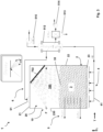
- the solar radiation is concentrated by a field of heliostats arranged on the ground and enters the receiver device through an opening, the latter preferably made on a side wall of the above-mentioned casing.
- the solar radiation entering through the opening hits one or more inner walls arranged in an empty region placed above the fluidized bed of particles, that is the freeboard thereof.
- Such inner walls have reflecting and/or re-radiating surfaces configured to receive the incident concentrated solar radiation and to reflect it towards the bed of particles both directly, and indirectly after multiple reflections on other inner surfaces.
- the energy fraction not reflected by the inner walls is absorbed by the same.
- the transmission of such absorbed energy to the external environment is prevented thanks to the use of materials or thermal insulating means associated to the walls themselves, in case as integrating portions thereof.
- the reflecting surfaces raise their own temperature and re-radiate the thermal energy towards the bed of particles, both directly and indirectly through re-radiations between the other internal surfaces.
- the vacant area, or irradiation region, delimited by the upper surface, or freeboard, of the bed of particles and by the inner walls of the device placed above said bed surface behaves as a radiating cavity, wherein the surfaces reflect and re-radiate the entering solar radiation according to their specific properties, directly or indirectly towards the bed of particles.
- the energy reflected - and in case re-radiated - by the walls is transmitted to the whole mass constituting the fluidized bed, which then can contain and store it until subsequent use.
- the fluidized bed is constituted by solid particles with preferably higher absorbance value than that of the above-mentioned reflecting walls, so as to favour the quick transfer of the energy reflected - and in case re-radiated - by the walls towards the fluidized bed itself.
- the fluidized bed can consist of particles made of sand or other granular material.
- the bed particles reach maximum temperatures preferably ⁇ 620°C.
- the reflecting surfaces have a high resistance to high temperatures, preferably over 1000°C, and/or a higher reflectivity than that of the bed of particles, preferably higher than 60% if calculated with reference to the standard regulations ASTM G173 and ISO7668.
- the type of preferred granular material for the bed of particles of the device 1 is of the type with thermal properties with high thermal capability and diffusivity.
- An example of preferred granular material is the river sand, which, apart from having said thermal properties, has a natural rounded shape of the particles minimizing the phenomenon of the mutual abrasion of the same.
- the inner walls of the casing 2 standing above the bed of particles 3, even when fluidized, are directly or indirectly involved by the solar radiation concentrated by the heliostats 501.
- Such walls of the irradiation region 350 have reflecting surfaces exposed within the compartment 20 made of materials and/or processing which can have reflectivity properties of different type, as described hereinafter.
- a tilted internal wall 701 which receives directly the concentrated solar radiation and has a reflecting and/or re-radiating surface, identified too with 701, operating in specular mode.
- the arrangement is so that the incident solar radiation is reflected almost wholly at the freeboard 35 of the bed 3, according to a reflection area corresponding to the cross section of the casing 2.
- the wall, schematized by the tilted shield 702 has a "glossy" optical behaviour.
- a "diffuse" behaviour is provided by means of a reflecting and/or re-radiating surface 703 belonging to a curved wall 24 joining between side skirt 22 and upper wall 21 of the casing 2.
- an additional tilted wall, or shield, 25 is also provided, having an auxiliary reflecting and/or re-radiating surface opposed to the surface 24.
- a schematization of a system 101 for closing the irradiation opening 10 is shown, in form of a hinged shield and in open position related to the phase for acquiring the concentrated radiation.
- the device 101 can be closed when it is not required to acquire energy, but rather to keep it.
- Said reflecting and/or re-radiating surfaces are constituted by materials resistant to high temperatures, induced by the high thermal flows thereto they are subjected, such as preferably ceramic tiles, refractory cements and/or analogous materials.
- the electromagnetic energy emitted as a whole by the inner surfaces 2, sum of the emitted radiations and the reflected ones, through the mutual view factors, by the surfaces 701-703 is absorbed by the bed of particles 3, advantageously selected with a higher absorption coefficient than all surfaces exposed to the concentrated solar radiation.
- the solar radiation reflected by the inner surfaces of the region 350 hits, directly or downwards of multiple reflections, according to the mutual view factors, the bed of particles 3.
- said inner surfaces absorb, according to their own absorption and reflectivity coefficients, a not reflected energy fraction, which causes the temperature raise of such surfaces which then re-radiate the solar energy towards the bed of particles, both directly and indirectly through re-radiations between the inner surfaces, according to the mutual view factors.
- Such configuration determines a device behaviour similar to that of a radiant cavity or black body, when said cavity is equipped with an opening towards outside with reduced sizes with respect to the average sizes of the cavity itself. Under such conditions, almost the whole concentrated solar radiation incident on the opening is repeatedly reflected, absorbed and re-radiated inside the cavity, so that only a minimum fraction thereof succeeds in outgoing and the so-captured solar energy remains accumulated in the fluidized bed of particles.
- the bed of particles 3 is put in motion by means of fluidization means 4 configured to supply and distribute a fluidization gas, in particular air, within the compartment 20.
- the means 4 comprises a plurality of elements supplying or inletting fluidization air 41, arranged at the lower base 23 of the casing 2 that is the base of the bed of particles 3.
- the route of the fluidization air within the bed of particles 3 is then from bottom upwards, in particular vertical or substantially vertical.
- the fluidization gas inlet takes place according to the longitudinal direction L.
- a uniform or substantially uniform fluidization of the bed of particles 3 is provided.
- the fluid dynamic regime of the bed 3 allows an effective heat exchange between the particles of its various portions. This is favoured by the fact that the bed particles are subjected to a continuous exchange and recirculation.
- the particles arranged on the freeboard 35 or near thereto absorb thermal energy by the reflected or re-radiated solar radiation and they cede it to the other bed particles.
- the thermal exchange between the particles is favoured by convective motions determined by the fluidization regime.
- Embodiment variants can provide a differentiated fluidization in different regions or portions of the bed 3.
- the fluidization of several bed regions or portions, or the fluidization regimes selectable therefor, can differentiate for speed, and in case rate, of the flow of fluidization air inletting the bed of particles 3.
- the fluidization elements can result to be arranged uniformly at the base of the bed of particles 3, such as in the present example, or to be positioned in differentiated way.
- Fluidization elements structurally analogous therebetween and in case controlled differently, for example in terms of speed and/or rate, can further be provided.
- the fluidization regime can even be of boiling type and/or, generally, a regime favouring convective motions of particles in the bed 3 or in regions or portions thereof.
- the fluidization regime selected for the whole bed or for a region or portion thereof can even be of so-called "spouted" type, for example like jet, fountain or impulse.
- the fluidized bed of spouted type generally has a hydro dynamic regime characterized by a jet of central fluidization gas at the base of same bed which, due to the strong speed difference between particles directly exposed to the jet and surrounding particles, creates a motion dragged by the bed column insisting on the jet itself and the overlooking (cylindrical) areas by creating, indeed, a fountain-like effect in the central portion fed by the solid dragged in the side portions of the jet.
- thermal exchange elements in particular tube bundles, are housed.
- Such exchangers with continuity or under selected operating conditions, can be crossed by an operating fluid, for example vapour or CO2.
- the operating fluid in a phase of thermal exchange, that is a phase of using the thermal energy accumulated in the bed of particles 3, the operating fluid can be made to flow in the tube bundles 5 and to receive heat from the bed particles.
- the tube bundles 5 can be at rest, that is in absence of circulation of operating fluid.
- the storage phase is activated in presence of sun.
- the phase of thermal exchange that is transfer of the thermal energy to the operating fluid, can be activated preferably even in absence of sun.
- the operating fluid outletting the device 1 under the conditions of design temperature and pressure can be made to expand in a turbine coupled to a generator for the production of electrical energy or can be used for other industrial purposes, for example for the production of fluid carriers to be used in industrial processes, in particular when thermal energy even at very high temperatures is required with continuity.
- the tube bundles 5 are connected to additional components of the plant, for example one or more turbines, condensers, heat exchangers, pumps and so on, each one known on itself.
- the device 1 further comprises means 6 for sucking fluidization air which has ended its own route within the bed of particles 3 and it comes out therefrom at the irradiation region 350. Such sucking means 6 is then configured to suck air within the casing 2 above the freeboard 35 of the bed of particles 3.
- the sucking means 6 comprises elements 61 for collecting air from the vacant space 350, for example in form of hood, arranged at the upper wall 21 of the casing 2.
- the sucking means 6 is configured even to avoid an emission, or a massive emission, of fluidization air and/or of the particles dragged thereby in the external environment through the opening 10.
- the sucking means 6 provides (not represented) control means, preferably rate sensors which, in synergy with additional (not illustrated) control means associated to the fluidization means 4, determine an air flow extracted from the device 1 equal or higher than the fluidization air flow entered the bed of particles 3.
- the device 1 provides a heat exchange between the (heated) fluidization air outletting the bed of particles 3 at the freeboard 35 of the latter and sucked by the means 6 and the fluidization air inletting the bed of particles 3 by means of the fluidization means 4.
- a heat regeneration is provided, obtained by means of thermal exchange means.
- This is represented schematically in the figures by means of thermal exchange components 512, components 513 for dedusting fluidization air, components 514 for sucking fluidization air from the external environment and components for inletting air 515 in the fluidization system belonging to the fluidization means 4.
- the device 1 has a calm chamber above the freeboard 35 of the bed of particles 3.
- Such calm chamber is meant as an area of low or null speed for the bed particles and it is defined, in the present example, by the vacant space 350.
- the calm chamber contributes to avoid a leak, or a massive leak, of air and/or particles through the opening 10.
- An exemplifying configuration of a plant like the one considered above, including a bed of particles of 350 tons, can be implemented with one or more of the following dimensional parameters:
- the device of the invention has modular nature, that fits well to be connected to one or more analogue devices in series or in parallel with respect to the thermal exchange.
- the types of devices according to the described different forms and embodiment variants can be favourably associated for a greater production and/or operating flexibility of the industrial plant.
- the plant based upon one or more of the devices of the invention can be advantageously associated to a photovoltaic system providing the daily production of electrical energy.
- the storage and transfer devices can be managed in regime of storing thermal energy of solar origin during the sunny hours and in regime of transferring thermal energy from twilight on.
- the plant can be associated to a plant for desalinating or other system for exploiting the thermal energy of solar origin.
- the devices can be managed in mixed regime: both for the storage, for the night production of electrical energy, and for contemporary daily transfer, by dedicating the related transfer of thermal energy to the continuous operation of the plant, for example desalinating operation.
- the device of the invention can be integrated with plants fed by other sources of renewable energy (for example photovoltaic, wind, geothermal) or not renewable to guarantee the energy production continuity with the purpose of reducing or eliminating the production of energy produced by not renewable sources.
- sources of renewable energy for example photovoltaic, wind, geothermal
- the invention further provides a method for the storage and exchange of thermal energy of solar origin, based upon the functionalities already described above in relation to the device and plant of the invention.
Landscapes
- Engineering & Computer Science (AREA)
- Thermal Sciences (AREA)
- General Engineering & Computer Science (AREA)
- Physics & Mathematics (AREA)
- Mechanical Engineering (AREA)
- Sustainable Development (AREA)
- Chemical & Material Sciences (AREA)
- Combustion & Propulsion (AREA)
- Sustainable Energy (AREA)
- Life Sciences & Earth Sciences (AREA)
- Engine Equipment That Uses Special Cycles (AREA)
- Photovoltaic Devices (AREA)
- Devices And Processes Conducted In The Presence Of Fluids And Solid Particles (AREA)
- Electromechanical Clocks (AREA)
- Telescopes (AREA)
Claims (22)
- Vorrichtung (1) zur Speicherung und Übertragung von Wärmeenergie solaren Ursprungs, wobei die Vorrichtung (1) umfasst:- ein Einschlussgehäuse (2) mit einer Bestrahlungsöffnung (10), die konfiguriert ist, um den Eintritt einer einfallenden Sonnenstrahlung in eine innerhalb des Gehäuses (2) definierte Bestrahlungsregion (350) zu ermöglichen, wobei die Bestrahlungsöffnung (10) an einer Seitenschürze (22) des Gehäuses (2) angeordnet ist;- ein Bett (3) aus fluidisierbaren Partikeln, das in dem Gehäuse (2) aufgenommen ist;- eine Vielzahl von reflektierenden Oberflächen (701; 702; 703), die innerhalb der Bestrahlungsregion (350) angeordnet sind, wobei jede der reflektierenden Oberflächen konfiguriert ist, um die durch die Bestrahlungsöffnung (10) eintretende Sonnenstrahlung direkt auf ein Freibord (35) des Betts von Partikeln (3) oder auf eine andere reflektierende Oberfläche der Bestrahlungsregion (350) zu reflektieren,wobei die Gesamtkonfiguration so beschaffen ist, dass die eintretende Strahlung auf das Freibord (35) des Betts von Partikeln (3) nach unten von Mehrfachreflexionen auf den reflektierenden Oberflächen (701; 702; 703) trifft,wobei die Partikel des Betts (3) ein höheres Absorptionsvermögen haben als die reflektierenden Oberflächen (701; 702; 703).
- Vorrichtung (1) nach Anspruch 1, ferner umfassend Wärmeaustauschmittel (5), die thermisch mit dem Bett von Partikeln (3) verbunden sind und die aktiviert werden können, um von dort Wärmeenergie zu empfangen, wobei die Gesamtkonfiguration so beschaffen ist, dass die Wärmeenergie von der eintretenden Sonnenstrahlung auf die Partikel des Betts (3) und zur gleichen oder späteren Zeit von den Partikeln auf die Wärmeaustauschmittel (5) übertragen wird, wobei die Wärmeaustauschmittel vorzugsweise eine oder mehrere der folgenden Komponenten umfassen: thermoelektrische Elemente; thermionische Elemente; thermophotovoltaische Elemente; Rohrbündel (5), die konfiguriert sind, um im Gebrauch von einem Betriebsfluid durchströmt zu werden.
- Vorrichtung (1) nach Anspruch 1 oder 2, umfassend Mittel zum Zuführen eines erhitzten Fluidisierungsgases, welches das Bett von Partikeln (3) an einen Benutzer abgibt.
- Vorrichtung (1) nach einem der vorstehenden Ansprüche, wobei die Bestrahlungsöffnung (10) die Bestrahlungsregion (350) des Gehäuses (2) in direkte Verbindung mit der äußeren Umgebung bringt, der im Gebrauch Verschluss- oder Abschirmmittel entzogen werden.
- Vorrichtung (1) nach einem der vorstehenden Ansprüche, wobei die Bestrahlungsöffnung (10) in der Nähe einer oberen Wand (21) des Gehäuses angeordnet ist.
- Vorrichtung (1) nach einem der vorstehenden Ansprüche, wobei das Freibord (35) des Betts von Partikeln (3) auch unter Fluidisierungsbedingungen unter einem unteren Rand (230) der Bestrahlungsöffnung (10) angeordnet ist.
- Vorrichtung (1) nach einem der vorstehenden Ansprüche, wobei die reflektierenden Oberflächen (701; 702; 703) konfiguriert sind, um in der Bestrahlungsregion (350) die von der Sonnenstrahlung absorbierte Wärmeenergie wieder abzustrahlen, vorteilhafterweise nach einer Strahlungshohlraumkonfiguration.
- Vorrichtung (1) nach einem der vorstehenden Ansprüche, wobei eine reflektierende Oberfläche (701; 702; 703) auf einer geneigten Wand implementiert ist, die innerhalb der Bestrahlungsregion (350) untergebracht ist, oder sie ist mit einer Wand (21, 22) verknüpft, die das Gehäuse (2) definiert, vorteilhafterweise mit gegenseitigen Sichtfaktoren, die geeignet sind, die aus der Öffnung (10) abgegebene Strahlungsenergie zu reduzieren.
- Vorrichtung (1) nach einem der vorstehenden Ansprüche, wobei die reflektierenden Oberflächen (701; 702; 703) ein Reflexionsvermögen haben, das zu einer der folgenden Schematisierungen gehört: spiegelndes Reflexionsvermögen, wobei der Strahlungsreflexionswinkel gleich dem Einfallswinkel ist; diffuses Reflexionsvermögen, mit Reflexion in alle Richtungen, unabhängig von der Strahlungseinfallsebene; glänzendes Reflexionsvermögen, mit einem Mischverhalten zwischen spiegelndem und diffusem Reflexionsvermögen.
- Vorrichtung (1) nach einem der vorstehenden Ansprüche, wobei das Gehäuse (2) mit Ausnahme der Bestrahlungsöffnung (10) aus wärmeisolierenden Materialien hergestellt ist.
- Vorrichtung (1) nach einem der vorstehenden Ansprüche, umfassend ein Fluidisierungsmittel (4), das konfiguriert ist, um ein Fluidisierungsgas, vorzugsweise Luft, in das Bett (3) aus fluidisierbaren festen Partikeln einzuleiten.
- Vorrichtung (1) nach dem vorstehenden Anspruch, umfassend Mittel zum selektiven Variieren der Strömungsgeschwindigkeit und/oder -rate des Fluidisierungsgases.
- Vorrichtung (1) nach einem der vorstehenden Ansprüche, umfassend ein Saugmittel (6), insbesondere mit einer im Wesentlichen haubenartigen Konfiguration (61), das konfiguriert ist, um ein Fluidisierungsgas oberhalb des Freibords (35) des Betts von Partikeln (3) anzusaugen.
- Vorrichtung (1) nach den Ansprüchen 11 und 13, umfassend Wärmeaustauschmittel (512) zwischen einem Fluidisierungsgas, welches das Bett von Partikeln (3) abgibt, und einem Fluidisierungsgas, das in das Bett von Partikeln (3) eintritt.
- Vorrichtung (1) nach einem der vorstehenden Ansprüche, umfassend Heizmittel, die thermisch mit dem Bett von Partikeln (3) verbunden sind, wobei die Heizmittel so konfiguriert sind, dass sie Wärmeenergie auf die Partikel übertragen.
- Vorrichtung (1) nach einem der vorstehenden Ansprüche, umfassend eine Stützstruktur (800), die konfiguriert ist, um das Gehäuse (2) in einer Erhöhung über dem Boden zu halten.
- Anlage zur Erzeugung von elektrischer und/oder Wärmeenergie, umfassend:▪ eine oder mehrere Vorrichtungen (1) nach einem der vorstehenden Ansprüche, die in großer Höhe angeordnet sind; und▪ Mittel zum Sammeln der Sonnenstrahlung (500), die auf dem Boden angeordnet sind und vorzugsweise eine Vielzahl von Heliostaten (501) umfassen,wobei die Konfiguration so beschaffen ist, dass die Sonnenstrahlung durch das Sammelmittel (500) gesammelt und auf die Bestrahlungsöffnung (10) der einen oder mehreren Vorrichtungen (1) konzentriert wird, wobei vorzugsweise das Sammelmittel (500) oder eine Untergruppe davon die Sonnenstrahlung in einem gemeinsamen Fokus (F) konzentriert, der an oder nahe der Bestrahlungsöffnung (10) einer Vorrichtung (1) angeordnet ist,wobei das Sammelmittel (500) eine Strahlungskonfiguration definiert, welche die Sonnenstrahlung von unten auf die eine oder mehrere Vorrichtungen (1) konvergieren lässt.
- Verfahren zum Erzeugen von elektrischer Energie und/oder Wärmeenergie, ausgehend von der Wärmeenergie einer Sonnenstrahlung, wobei das Verfahren bereitstellt:- eine Konzentration der Sonnenstrahlung an einer Bestrahlungsöffnung (10) einer Empfangsvorrichtung (1), die ein Bett zur Speicherung von Wärmeenergie vom Typ mit fluidisierbaren Partikeln (3) umfasst, und- Mehrfachreflexionen der Sonnenstrahlung auf dem Bett von Partikeln durch eine Vielzahl von reflektierenden Oberflächen (701 bis 703), die unterhalb der Einstrahlungsöffnung (10) angeordnet sind, wobei das Verfahren eine Vorrichtung oder eine Anlage nach einem der Ansprüche 1 bis 17 verwendet.
- Verfahren nach dem vorstehenden Anspruch, umfassend eine Phase der Übertragung von Wärmeenergie durch die Partikel des Betts (3), die selektiv zur gleichen oder späteren Zeit in Bezug auf eine Phase der Speicherung von Wärmeenergie aktiviert werden kann.
- Verfahren nach Anspruch 18 oder 19, das eine Phase des Verwendens eines erhitzten Fluidisierungsgases umfasst, welches das Bett von Partikeln (3) abgibt.
- Verfahren nach einem der Ansprüche 18 bis 20, umfassend eine Phase der Fluidisierung der Partikel des Betts (3), die unter ausgewählten Betriebsbedingungen aktiviert wird.
- Verfahren nach dem vorstehenden Anspruch, das ein selektives Einstellen der Strömungsgeschwindigkeit und/oder -rate eines Fluidisierungsgases bereitstellt.
Applications Claiming Priority (1)
| Application Number | Priority Date | Filing Date | Title |
|---|---|---|---|
| PCT/IB2020/050828 WO2021156649A1 (en) | 2020-02-03 | 2020-02-03 | Device for the storage of thermal energy of solar origin based upon multiple reflections |
Publications (2)
| Publication Number | Publication Date |
|---|---|
| EP4100685A1 EP4100685A1 (de) | 2022-12-14 |
| EP4100685B1 true EP4100685B1 (de) | 2025-01-29 |
Family
ID=69903714
Family Applications (1)
| Application Number | Title | Priority Date | Filing Date |
|---|---|---|---|
| EP20713088.1A Active EP4100685B1 (de) | 2020-02-03 | 2020-02-03 | Vorrichtung zur speicherung thermischer energie von solarursprung mit mehreren reflexionen |
Country Status (13)
| Country | Link |
|---|---|
| US (1) | US12345448B2 (de) |
| EP (1) | EP4100685B1 (de) |
| JP (1) | JP7604504B2 (de) |
| KR (1) | KR102759635B1 (de) |
| CN (1) | CN115038913B (de) |
| AU (1) | AU2020427248B2 (de) |
| CL (1) | CL2022002082A1 (de) |
| ES (1) | ES3010473T3 (de) |
| IL (1) | IL295315B2 (de) |
| MX (1) | MX2022009456A (de) |
| PT (1) | PT4100685T (de) |
| WO (1) | WO2021156649A1 (de) |
| ZA (1) | ZA202209787B (de) |
Families Citing this family (1)
| Publication number | Priority date | Publication date | Assignee | Title |
|---|---|---|---|---|
| GB2620356B (en) * | 2022-03-01 | 2025-07-09 | Hamdan Mustapha | Apparatus and system for generating thermal energy using concentrated solar power |
Family Cites Families (16)
| Publication number | Priority date | Publication date | Assignee | Title |
|---|---|---|---|---|
| US3908632A (en) * | 1974-06-24 | 1975-09-30 | Universal Oil Prod Co | Solar heat absorbing system |
| US4455153A (en) | 1978-05-05 | 1984-06-19 | Jakahi Douglas Y | Apparatus for storing solar energy in synthetic fuels |
| US4727930A (en) | 1981-08-17 | 1988-03-01 | The Board Of Regents Of The University Of Washington | Heat transfer and storage system |
| ITLE20090011A1 (it) | 2009-09-04 | 2009-12-04 | Riccardis Andrea De | Sistema di accumulo dell'energia termica da radiazione solare. |
| IT1399952B1 (it) | 2010-04-29 | 2013-05-09 | Magaldi Ind Srl | Dispositivo e sistema di stoccaggio e trasporto ad alto livello di efficienza energetica |
| AU2011264424B2 (en) * | 2010-06-11 | 2015-05-28 | Penworth Pty Ltd | Apparatus and method for solar energy collection and conversion |
| IT1402159B1 (it) | 2010-10-15 | 2013-08-28 | Enel Ingegneria E Innovazione S P A | Dispositivo, impianto e metodo ad alto livello di efficienza energetica per l'accumulo e l'impiego di energia termica di origine solare. |
| EP2669514A4 (de) | 2011-01-30 | 2015-05-20 | Yuqi Chen | Sonnenwärmespeicherung und hochtemperatur-gaserzeugungssystem mit fliessendem sand als arbeitsmittel |
| ITRM20110234A1 (it) * | 2011-05-10 | 2012-11-11 | Magaldi Ind Srl | Ricevitore/scambiatore e metodo di connessione ad alto livello di efficienza energetica. |
| US20130255667A1 (en) | 2012-04-02 | 2013-10-03 | Colorado School Of Mines | Solid particle thermal energy storage design for a fluidized-bed concentrating solar power plant |
| ITRM20120135A1 (it) | 2012-04-03 | 2013-10-04 | Magaldi Ind Srl | Dispositivo, impianto e metodo ad alto livello di efficienza energetica per l'accumulo e l'impiego di energia termica di origine solare. |
| JP6165743B2 (ja) | 2012-09-05 | 2017-07-19 | 国立大学法人 新潟大学 | 太陽光を利用した集熱蓄熱装置 |
| JP6440267B2 (ja) * | 2014-05-13 | 2018-12-19 | 国立大学法人 新潟大学 | 集光太陽光の受熱装置、反応装置及び加熱装置 |
| ITUB20152907A1 (it) | 2015-08-05 | 2017-02-05 | Magaldi Ind Srl | Dispositivo, impianto e metodo ad alto livello di efficienza energetica per l?impiego di energia termica di origine solare |
| DE102016216733B4 (de) * | 2016-06-23 | 2018-03-22 | Deutsches Zentrum für Luft- und Raumfahrt e.V. | Solarstrahlungsreceiver zur solaren Bestrahlung von Feststoffpartikeln, eine Industrieanlage mit einem Solarstrahlungsreceiver, sowie ein Verfahren zur solaren Bestrahlung von Feststoffpartikeln |
| TW201839259A (zh) | 2017-02-01 | 2018-11-01 | 義大利商馬加帝電力公司 | 使用源自太陽之熱能之高能效率裝置、系統及方法 |
-
2020
- 2020-02-03 KR KR1020227029801A patent/KR102759635B1/ko active Active
- 2020-02-03 IL IL295315A patent/IL295315B2/en unknown
- 2020-02-03 EP EP20713088.1A patent/EP4100685B1/de active Active
- 2020-02-03 WO PCT/IB2020/050828 patent/WO2021156649A1/en not_active Ceased
- 2020-02-03 ES ES20713088T patent/ES3010473T3/es active Active
- 2020-02-03 US US17/759,157 patent/US12345448B2/en active Active
- 2020-02-03 MX MX2022009456A patent/MX2022009456A/es unknown
- 2020-02-03 AU AU2020427248A patent/AU2020427248B2/en active Active
- 2020-02-03 CN CN202080095558.6A patent/CN115038913B/zh active Active
- 2020-02-03 JP JP2022545779A patent/JP7604504B2/ja active Active
- 2020-02-03 PT PT207130881T patent/PT4100685T/pt unknown
-
2022
- 2022-08-02 CL CL2022002082A patent/CL2022002082A1/es unknown
- 2022-09-01 ZA ZA2022/09787A patent/ZA202209787B/en unknown
Also Published As
| Publication number | Publication date |
|---|---|
| CL2022002082A1 (es) | 2023-03-03 |
| IL295315A (en) | 2022-10-01 |
| WO2021156649A1 (en) | 2021-08-12 |
| BR112022014736A2 (pt) | 2022-10-04 |
| AU2020427248B2 (en) | 2024-03-07 |
| AU2020427248A1 (en) | 2022-08-25 |
| KR102759635B1 (ko) | 2025-01-23 |
| EP4100685A1 (de) | 2022-12-14 |
| US20230064799A1 (en) | 2023-03-02 |
| CN115038913A (zh) | 2022-09-09 |
| JP2023522531A (ja) | 2023-05-31 |
| JP7604504B2 (ja) | 2024-12-23 |
| MX2022009456A (es) | 2022-08-25 |
| US12345448B2 (en) | 2025-07-01 |
| CN115038913B (zh) | 2025-08-22 |
| KR20220130224A (ko) | 2022-09-26 |
| IL295315B2 (en) | 2026-04-01 |
| IL295315B1 (en) | 2025-12-01 |
| ES3010473T3 (en) | 2025-04-03 |
| ZA202209787B (en) | 2024-01-31 |
| PT4100685T (pt) | 2025-03-14 |
Similar Documents
| Publication | Publication Date | Title |
|---|---|---|
| AU2008351048B2 (en) | Hybrid solar heat power generation device | |
| US7975685B2 (en) | Solar collecting and utilizing device | |
| EP3221649B1 (de) | Festkörpersolarwärmekollektor | |
| US8413442B2 (en) | System for sustaining and storing green solar energy | |
| WO2012153264A2 (en) | Exchanger/collector and connection method with a high level of energy efficiency | |
| WO2020079189A1 (en) | Heat transfer and thermal storage apparatus | |
| Mills | Solar thermal electricity | |
| AU2009334310A1 (en) | A solar energy collecting system | |
| EP4100685B1 (de) | Vorrichtung zur speicherung thermischer energie von solarursprung mit mehreren reflexionen | |
| US9939178B2 (en) | Solids-based concentrated solar power receiver | |
| WO2012120016A1 (en) | Receiver for a beam down power plant, system with the receiver and use of the system | |
| GB1578996A (en) | Assembly for collecting solar energy | |
| KR100861567B1 (ko) | 타워형 태양열 발전기 | |
| BR112022014736B1 (pt) | Dispositivo para armazenamento e transferência de energia térmica de origem solar, instalação para produção de energia elétrica e/ou térmica, método de produção de energia elétrica e/ou térmica | |
| GB2473328A (en) | Apparatus for generating electricity and heat from solar energy | |
| WO2018207106A2 (en) | Device, plant and method for storing and transferring thermal energy of solar origin | |
| EP2730855A1 (de) | Empfänger für eine thermosolaranlage und thermosolaranlage mit solchen empfänger | |
| RU2007108898A (ru) | Гелиоаэробарическая теплоэлектростанция | |
| Vasylyev et al. | High Performance Concentrating Photovoltaic Module Designs Employing Reflective Lens Optics |
Legal Events
| Date | Code | Title | Description |
|---|---|---|---|
| STAA | Information on the status of an ep patent application or granted ep patent |
Free format text: STATUS: UNKNOWN |
|
| STAA | Information on the status of an ep patent application or granted ep patent |
Free format text: STATUS: THE INTERNATIONAL PUBLICATION HAS BEEN MADE |
|
| PUAI | Public reference made under article 153(3) epc to a published international application that has entered the european phase |
Free format text: ORIGINAL CODE: 0009012 |
|
| STAA | Information on the status of an ep patent application or granted ep patent |
Free format text: STATUS: REQUEST FOR EXAMINATION WAS MADE |
|
| 17P | Request for examination filed |
Effective date: 20220811 |
|
| AK | Designated contracting states |
Kind code of ref document: A1 Designated state(s): AL AT BE BG CH CY CZ DE DK EE ES FI FR GB GR HR HU IE IS IT LI LT LU LV MC MK MT NL NO PL PT RO RS SE SI SK SM TR |
|
| REG | Reference to a national code |
Ref country code: HK Ref legal event code: DE Ref document number: 40080591 Country of ref document: HK |
|
| DAV | Request for validation of the european patent (deleted) | ||
| DAX | Request for extension of the european patent (deleted) | ||
| GRAP | Despatch of communication of intention to grant a patent |
Free format text: ORIGINAL CODE: EPIDOSNIGR1 |
|
| STAA | Information on the status of an ep patent application or granted ep patent |
Free format text: STATUS: GRANT OF PATENT IS INTENDED |
|
| INTG | Intention to grant announced |
Effective date: 20241029 |
|
| GRAS | Grant fee paid |
Free format text: ORIGINAL CODE: EPIDOSNIGR3 |
|
| GRAA | (expected) grant |
Free format text: ORIGINAL CODE: 0009210 |
|
| STAA | Information on the status of an ep patent application or granted ep patent |
Free format text: STATUS: THE PATENT HAS BEEN GRANTED |
|
| AK | Designated contracting states |
Kind code of ref document: B1 Designated state(s): AL AT BE BG CH CY CZ DE DK EE ES FI FR GB GR HR HU IE IS IT LI LT LU LV MC MK MT NL NO PL PT RO RS SE SI SK SM TR |
|
| REG | Reference to a national code |
Ref country code: GB Ref legal event code: FG4D |
|
| REG | Reference to a national code |
Ref country code: CH Ref legal event code: EP |
|
| REG | Reference to a national code |
Ref country code: DE Ref legal event code: R096 Ref document number: 602020045486 Country of ref document: DE |
|
| REG | Reference to a national code |
Ref country code: IE Ref legal event code: FG4D |
|
| REG | Reference to a national code |
Ref country code: PT Ref legal event code: SC4A Ref document number: 4100685 Country of ref document: PT Date of ref document: 20250314 Kind code of ref document: T Free format text: AVAILABILITY OF NATIONAL TRANSLATION Effective date: 20250310 |
|
| RAP4 | Party data changed (patent owner data changed or rights of a patent transferred) |
Owner name: MAGALDI POWER S.P.A. |
|
| REG | Reference to a national code |
Ref country code: GR Ref legal event code: EP Ref document number: 20250400461 Country of ref document: GR Effective date: 20250409 |
|
| REG | Reference to a national code |
Ref country code: NL Ref legal event code: MP Effective date: 20250129 |
|
| PG25 | Lapsed in a contracting state [announced via postgrant information from national office to epo] |
Ref country code: NL Free format text: LAPSE BECAUSE OF FAILURE TO SUBMIT A TRANSLATION OF THE DESCRIPTION OR TO PAY THE FEE WITHIN THE PRESCRIBED TIME-LIMIT Effective date: 20250129 |
|
| PG25 | Lapsed in a contracting state [announced via postgrant information from national office to epo] |
Ref country code: RS Free format text: LAPSE BECAUSE OF FAILURE TO SUBMIT A TRANSLATION OF THE DESCRIPTION OR TO PAY THE FEE WITHIN THE PRESCRIBED TIME-LIMIT Effective date: 20250429 |
|
| PG25 | Lapsed in a contracting state [announced via postgrant information from national office to epo] |
Ref country code: FI Free format text: LAPSE BECAUSE OF FAILURE TO SUBMIT A TRANSLATION OF THE DESCRIPTION OR TO PAY THE FEE WITHIN THE PRESCRIBED TIME-LIMIT Effective date: 20250129 |
|
| PG25 | Lapsed in a contracting state [announced via postgrant information from national office to epo] |
Ref country code: PL Free format text: LAPSE BECAUSE OF FAILURE TO SUBMIT A TRANSLATION OF THE DESCRIPTION OR TO PAY THE FEE WITHIN THE PRESCRIBED TIME-LIMIT Effective date: 20250129 |
|
| PGFP | Annual fee paid to national office [announced via postgrant information from national office to epo] |
Ref country code: ES Payment date: 20250331 Year of fee payment: 6 |
|
| REG | Reference to a national code |
Ref country code: LT Ref legal event code: MG9D |
|
| PG25 | Lapsed in a contracting state [announced via postgrant information from national office to epo] |
Ref country code: IS Free format text: LAPSE BECAUSE OF FAILURE TO SUBMIT A TRANSLATION OF THE DESCRIPTION OR TO PAY THE FEE WITHIN THE PRESCRIBED TIME-LIMIT Effective date: 20250529 Ref country code: NO Free format text: LAPSE BECAUSE OF FAILURE TO SUBMIT A TRANSLATION OF THE DESCRIPTION OR TO PAY THE FEE WITHIN THE PRESCRIBED TIME-LIMIT Effective date: 20250429 |
|
| REG | Reference to a national code |
Ref country code: AT Ref legal event code: MK05 Ref document number: 1763799 Country of ref document: AT Kind code of ref document: T Effective date: 20250129 |
|
| PG25 | Lapsed in a contracting state [announced via postgrant information from national office to epo] |
Ref country code: HR Free format text: LAPSE BECAUSE OF FAILURE TO SUBMIT A TRANSLATION OF THE DESCRIPTION OR TO PAY THE FEE WITHIN THE PRESCRIBED TIME-LIMIT Effective date: 20250129 |
|
| PG25 | Lapsed in a contracting state [announced via postgrant information from national office to epo] |
Ref country code: LV Free format text: LAPSE BECAUSE OF FAILURE TO SUBMIT A TRANSLATION OF THE DESCRIPTION OR TO PAY THE FEE WITHIN THE PRESCRIBED TIME-LIMIT Effective date: 20250129 |
|
| PG25 | Lapsed in a contracting state [announced via postgrant information from national office to epo] |
Ref country code: BG Free format text: LAPSE BECAUSE OF FAILURE TO SUBMIT A TRANSLATION OF THE DESCRIPTION OR TO PAY THE FEE WITHIN THE PRESCRIBED TIME-LIMIT Effective date: 20250129 |
|
| PG25 | Lapsed in a contracting state [announced via postgrant information from national office to epo] |
Ref country code: AT Free format text: LAPSE BECAUSE OF FAILURE TO SUBMIT A TRANSLATION OF THE DESCRIPTION OR TO PAY THE FEE WITHIN THE PRESCRIBED TIME-LIMIT Effective date: 20250129 |
|
| PG25 | Lapsed in a contracting state [announced via postgrant information from national office to epo] |
Ref country code: SE Free format text: LAPSE BECAUSE OF FAILURE TO SUBMIT A TRANSLATION OF THE DESCRIPTION OR TO PAY THE FEE WITHIN THE PRESCRIBED TIME-LIMIT Effective date: 20250129 |
|
| REG | Reference to a national code |
Ref country code: CH Ref legal event code: PL |
|
| PG25 | Lapsed in a contracting state [announced via postgrant information from national office to epo] |
Ref country code: SM Free format text: LAPSE BECAUSE OF FAILURE TO SUBMIT A TRANSLATION OF THE DESCRIPTION OR TO PAY THE FEE WITHIN THE PRESCRIBED TIME-LIMIT Effective date: 20250129 |
|
| PG25 | Lapsed in a contracting state [announced via postgrant information from national office to epo] |
Ref country code: DK Free format text: LAPSE BECAUSE OF FAILURE TO SUBMIT A TRANSLATION OF THE DESCRIPTION OR TO PAY THE FEE WITHIN THE PRESCRIBED TIME-LIMIT Effective date: 20250129 |
|
| PG25 | Lapsed in a contracting state [announced via postgrant information from national office to epo] |
Ref country code: MC Free format text: LAPSE BECAUSE OF FAILURE TO SUBMIT A TRANSLATION OF THE DESCRIPTION OR TO PAY THE FEE WITHIN THE PRESCRIBED TIME-LIMIT Effective date: 20250129 |
|
| PG25 | Lapsed in a contracting state [announced via postgrant information from national office to epo] |
Ref country code: LU Free format text: LAPSE BECAUSE OF NON-PAYMENT OF DUE FEES Effective date: 20250203 |
|
| PG25 | Lapsed in a contracting state [announced via postgrant information from national office to epo] |
Ref country code: CH Free format text: LAPSE BECAUSE OF NON-PAYMENT OF DUE FEES Effective date: 20250228 |
|
| PG25 | Lapsed in a contracting state [announced via postgrant information from national office to epo] |
Ref country code: CZ Free format text: LAPSE BECAUSE OF FAILURE TO SUBMIT A TRANSLATION OF THE DESCRIPTION OR TO PAY THE FEE WITHIN THE PRESCRIBED TIME-LIMIT Effective date: 20250129 Ref country code: EE Free format text: LAPSE BECAUSE OF FAILURE TO SUBMIT A TRANSLATION OF THE DESCRIPTION OR TO PAY THE FEE WITHIN THE PRESCRIBED TIME-LIMIT Effective date: 20250129 |
|
| PG25 | Lapsed in a contracting state [announced via postgrant information from national office to epo] |
Ref country code: RO Free format text: LAPSE BECAUSE OF FAILURE TO SUBMIT A TRANSLATION OF THE DESCRIPTION OR TO PAY THE FEE WITHIN THE PRESCRIBED TIME-LIMIT Effective date: 20250129 |
|
| PG25 | Lapsed in a contracting state [announced via postgrant information from national office to epo] |
Ref country code: SK Free format text: LAPSE BECAUSE OF FAILURE TO SUBMIT A TRANSLATION OF THE DESCRIPTION OR TO PAY THE FEE WITHIN THE PRESCRIBED TIME-LIMIT Effective date: 20250129 |
|
| REG | Reference to a national code |
Ref country code: DE Ref legal event code: R097 Ref document number: 602020045486 Country of ref document: DE |
|
| PLBE | No opposition filed within time limit |
Free format text: ORIGINAL CODE: 0009261 |
|
| STAA | Information on the status of an ep patent application or granted ep patent |
Free format text: STATUS: NO OPPOSITION FILED WITHIN TIME LIMIT |
|
| REG | Reference to a national code |
Ref country code: BE Ref legal event code: MM Effective date: 20250228 |
|
| GBPC | Gb: european patent ceased through non-payment of renewal fee |
Effective date: 20250429 |
|
| 26N | No opposition filed |
Effective date: 20251030 |
|
| PG25 | Lapsed in a contracting state [announced via postgrant information from national office to epo] |
Ref country code: GB Free format text: LAPSE BECAUSE OF NON-PAYMENT OF DUE FEES Effective date: 20250429 |
|
| PG25 | Lapsed in a contracting state [announced via postgrant information from national office to epo] |
Ref country code: BE Free format text: LAPSE BECAUSE OF NON-PAYMENT OF DUE FEES Effective date: 20250228 |
|
| PG25 | Lapsed in a contracting state [announced via postgrant information from national office to epo] |
Ref country code: IE Free format text: LAPSE BECAUSE OF NON-PAYMENT OF DUE FEES Effective date: 20250203 |
|
| PGFP | Annual fee paid to national office [announced via postgrant information from national office to epo] |
Ref country code: DE Payment date: 20260218 Year of fee payment: 7 |
|
| PGFP | Annual fee paid to national office [announced via postgrant information from national office to epo] |
Ref country code: IT Payment date: 20260127 Year of fee payment: 7 |
|
| PGFP | Annual fee paid to national office [announced via postgrant information from national office to epo] |
Ref country code: FR Payment date: 20260219 Year of fee payment: 7 |
|
| PGFP | Annual fee paid to national office [announced via postgrant information from national office to epo] |
Ref country code: TR Payment date: 20260128 Year of fee payment: 7 |
|
| PGFP | Annual fee paid to national office [announced via postgrant information from national office to epo] |
Ref country code: PT Payment date: 20260122 Year of fee payment: 7 |
|
| PGFP | Annual fee paid to national office [announced via postgrant information from national office to epo] |
Ref country code: GR Payment date: 20260218 Year of fee payment: 7 |