EP4100694B1 - Procédé et scanner intrabuccaux pour détection de topographie de surface d'un objet translucide, en particulier un objet dentaire - Google Patents
Procédé et scanner intrabuccaux pour détection de topographie de surface d'un objet translucide, en particulier un objet dentaire Download PDFInfo
- Publication number
- EP4100694B1 EP4100694B1 EP21836376.0A EP21836376A EP4100694B1 EP 4100694 B1 EP4100694 B1 EP 4100694B1 EP 21836376 A EP21836376 A EP 21836376A EP 4100694 B1 EP4100694 B1 EP 4100694B1
- Authority
- EP
- European Patent Office
- Prior art keywords
- light
- measuring
- projection
- topography
- image
- Prior art date
- Legal status (The legal status is an assumption and is not a legal conclusion. Google has not performed a legal analysis and makes no representation as to the accuracy of the status listed.)
- Active
Links
Images




Classifications
-
- G—PHYSICS
- G01—MEASURING; TESTING
- G01B—MEASURING LENGTH, THICKNESS OR SIMILAR LINEAR DIMENSIONS; MEASURING ANGLES; MEASURING AREAS; MEASURING IRREGULARITIES OF SURFACES OR CONTOURS
- G01B11/00—Measuring arrangements characterised by the use of optical techniques
- G01B11/24—Measuring arrangements characterised by the use of optical techniques for measuring contours or curvatures
- G01B11/25—Measuring arrangements characterised by the use of optical techniques for measuring contours or curvatures by projecting a pattern, e.g. one or more lines, moiré fringes on the object
-
- A—HUMAN NECESSITIES
- A61—MEDICAL OR VETERINARY SCIENCE; HYGIENE
- A61C—DENTISTRY; APPARATUS OR METHODS FOR ORAL OR DENTAL HYGIENE
- A61C9/00—Impression cups, i.e. impression trays; Impression methods
- A61C9/004—Means or methods for taking digitized impressions
- A61C9/0046—Data acquisition means or methods
- A61C9/0053—Optical means or methods, e.g. scanning the teeth by a laser or light beam
- A61C9/006—Optical means or methods, e.g. scanning the teeth by a laser or light beam projecting one or more stripes or patterns on the teeth
-
- A—HUMAN NECESSITIES
- A61—MEDICAL OR VETERINARY SCIENCE; HYGIENE
- A61C—DENTISTRY; APPARATUS OR METHODS FOR ORAL OR DENTAL HYGIENE
- A61C9/00—Impression cups, i.e. impression trays; Impression methods
- A61C9/004—Means or methods for taking digitized impressions
- A61C9/0046—Data acquisition means or methods
- A61C9/0053—Optical means or methods, e.g. scanning the teeth by a laser or light beam
-
- A—HUMAN NECESSITIES
- A61—MEDICAL OR VETERINARY SCIENCE; HYGIENE
- A61C—DENTISTRY; APPARATUS OR METHODS FOR ORAL OR DENTAL HYGIENE
- A61C9/00—Impression cups, i.e. impression trays; Impression methods
- A61C9/004—Means or methods for taking digitized impressions
- A61C9/0046—Data acquisition means or methods
- A61C9/0053—Optical means or methods, e.g. scanning the teeth by a laser or light beam
- A61C9/0066—Depth determination through adaptive focusing
-
- G—PHYSICS
- G01—MEASURING; TESTING
- G01B—MEASURING LENGTH, THICKNESS OR SIMILAR LINEAR DIMENSIONS; MEASURING ANGLES; MEASURING AREAS; MEASURING IRREGULARITIES OF SURFACES OR CONTOURS
- G01B11/00—Measuring arrangements characterised by the use of optical techniques
- G01B11/24—Measuring arrangements characterised by the use of optical techniques for measuring contours or curvatures
- G01B11/25—Measuring arrangements characterised by the use of optical techniques for measuring contours or curvatures by projecting a pattern, e.g. one or more lines, moiré fringes on the object
- G01B11/2513—Measuring arrangements characterised by the use of optical techniques for measuring contours or curvatures by projecting a pattern, e.g. one or more lines, moiré fringes on the object with several lines being projected in more than one direction, e.g. grids, patterns
-
- G—PHYSICS
- G02—OPTICS
- G02B—OPTICAL ELEMENTS, SYSTEMS OR APPARATUS
- G02B27/00—Optical systems or apparatus not provided for by any of the groups G02B1/00 - G02B26/00, G02B30/00
- G02B27/42—Diffraction optics, i.e. systems including a diffractive element being designed for providing a diffractive effect
- G02B27/4205—Diffraction optics, i.e. systems including a diffractive element being designed for providing a diffractive effect having a diffractive optical element [DOE] contributing to image formation, e.g. whereby modulation transfer function MTF or optical aberrations are relevant
- G02B27/4227—Diffraction optics, i.e. systems including a diffractive element being designed for providing a diffractive effect having a diffractive optical element [DOE] contributing to image formation, e.g. whereby modulation transfer function MTF or optical aberrations are relevant in image scanning systems
Definitions
- the invention relates to a method and an intraoral scanner for detecting the topography of the surface of a translucent, in particular dental, object.
- intraoral scanners for detecting the topography of the surface of translucent, especially dental, objects are known from the prior art and are used in particular in the field of dentistry in order to capture the dental situation of a patient three-dimensionally (3D capture) and digitally.
- the detection is typically carried out using an intraoral scanner (also called a 3D intraoral camera or 3D intraoral scanner), which includes a so-called hand piece with a detection device.
- an intraoral scanner also called a 3D intraoral camera or 3D intraoral scanner
- an operator guides a so-called scanning tip of the handpiece in the patient's oral cavity over the dental region to be captured Surface.
- the dental surface is usually formed by dental objects such as teeth, gums, tooth restorations or dental aids such as so-called “scan bodies” or “abutments”.
- the result of the scanning process is a captured topography of the captured object (also in the area of intraoral scanning called a “digital (dental) impression”).
- topography refers to the description of the (geometric) shape of an object.
- a topography recorded by measurement can, for example, be represented by a plurality of three-dimensional measuring points (also called a point cloud), by a three-dimensional triangular network (or "triangle mesh”), or by one or more depth maps . "depth map”).
- a depth map is a digital image consisting of image elements (pixels), where the pixels represent “depth values”.
- the depth values of a depth map correspond to respective distances from a local one Coordinate system of the intraoral scanner (or generally a 3D/depth camera) to the surface of the captured object, from the respective capture position or viewing direction.
- Intraoral scanners can also be used outside of oral cavities to capture the topography of the surface of dental or other objects (e.g. a tooth model or a component not related to dentistry).
- partial topographies of the currently detectable (or viewable) partial surfaces are recorded in the form of three-dimensional data.
- This partial surface usually corresponds to a small section of the entire surface to be recorded.
- To capture the (overall) topography of the entire surface a large number of captured partial topographies of partial surfaces are put together during the movement of the scanning tip (over the surface to be captured), which is also known as "registration”, “alignment”, “stitching”, or " SLAM” (“Simultaneous Localization and Mapping”) is called.
- the large number of partial topographies of the partial surfaces are thus combined to form the (overall) topography of the surface to be detected, whereby a three-dimensional detection of the entire surface (region) to be detected is achieved.
- the topography is thus captured while the scanning tip is moved (continuously) over the surface to be captured at a certain movement speed (along a movement path). It is beneficial for practical use if the topography can be captured reliably with a high overall capture accuracy, even at relatively high movement speeds.
- the topography of the surface is recorded with an accuracy of at least 50 ⁇ m (overall recording accuracy).
- the present invention relates to the known method of “structured lighting” in conjunction with the known method of triangulation, also collectively referred to as “active triangulation”.
- one or more measurement patterns which typically each include several measurement elements (e.g. measurement lines, point-shaped measurement elements), are projected onto a surface of an object in the direction of a projection axis using a light source.
- the surface of the object is illuminated by the measuring pattern (or by the measuring elements), so that only the sections of the surface assigned to the measuring elements are illuminated by the light source with high light intensity, while the areas of the surface lying between the illuminated sections are not (directly) illuminated. are illuminated by the light source and therefore have a lower light intensity.
- the light intensity therefore varies locally along the surface, which is why this type of surface illumination is also referred to as structured lighting.
- a detection device eg a camera
- an image of the measurement elements of the measurement pattern projected onto the surface is recorded along a detection axis that deviates from the projection axis.
- the topography of the object surface causes a spatial distortion of the measurement patterns from the perspective of the detection device. This distortion is used as part of triangulation to record the topography of the object surface using geometric calculations by determining three-dimensional coordinates for a large number of measuring points located on the measuring elements.
- the correct determination of the three-dimensional coordinates of the measuring points requires the solution of the so-called correspondence problem, according to which each individual measuring element must be individually identified in the image captured by the detection device.
- (the individual) measurement elements are coded or indexed and thus enable the correspondence problem to be solved.
- the measuring elements are coded, for example, by means of different colors (color-coded measuring elements) and/or by a characteristic presence or absence of measuring elements in captured images (presence-coded measuring elements).
- color-coded measuring elements for example, by means of different colors (color-coded measuring elements) and/or by a characteristic presence or absence of measuring elements in captured images (presence-coded measuring elements).
- temporal sequences temporary coding
- spatial sequences spatial coding
- hybrid forms of both approaches are known (hybrid coding).
- temporal coding With temporal coding, a measuring element is encoded via an image content that changes characteristically across multiple projections/captures, for example a measurement line that is characteristically present or absent in the captured images in a sequence of multiple projections/captures.
- image content that changes characteristically across multiple projections/captures, for example a measurement line that is characteristically present or absent in the captured images in a sequence of multiple projections/captures.
- each measuring element is coded individually, i.e. no environment of measuring elements is required to solve the correspondence problem. In contrast, there is a comparatively high number of projections/recordings.
- a measuring element is encoded via a characteristic image content located in the area surrounding the measuring element, for example the presence or absence of further (measuring) lines in the area surrounding the measuring element. Accordingly, solving the correspondence problem requires the detection of an environment of measurement elements; a single measurement element cannot be resolved immediately. In this context, one also speaks of a minimally resolvable sequence or environment of measuring elements; for example, a detection of n neighboring measuring elements could be necessary to solve the correspondence problem for these measuring elements. This disadvantage is offset by the advantage compared to a comparatively small number of projections/captures.
- Hybrid coding corresponds to a combination of spatial and temporal coding.
- the choice of a coding approach depends crucially on the framework conditions and objectives of the respective application.
- hybrid coding can represent a compromise, consisting of a number of projections/acquisitions that is lower than with purely temporal coding, and a minimally resolvable sequence or environment of measurement elements that is lower than with purely spatial coding.
- the measuring patterns can include one or more measuring lines (as measuring elements) or can be designed completely differently, e.g. in the form of dot patterns or color-coded stripe patterns.
- the document WO 2018073824 A1 discloses a device and a method for capturing intraoral scenes using structured lighting and triangulation.
- the capture is carried out by means of a color-coded, imaging measurement pattern projection onto the object to be captured and the recording of the projected measurement pattern using a camera.
- a 3D capture is realized using the well-known active triangulation method.
- the image-projected, color-coded measurement pattern can be generated using methods known in the prior art with a white light source and corresponding color filters, which are present, for example, in the form of a slide. This slide is imaged onto the object surface by a projection lens.
- the document DE 102007054907 A1 also describes a method and an associated device for the optical measurement of dental objects using a triangulation method, whereby (at least) two different measurement patterns are projected and recorded at the same time.
- the measurement patterns are generated by shading in which light sources shine through aperture means designed as grids (see paragraph [0091]).
- the document WO 2020102658 A2 discloses a laser projection system for an intraoral scanner.
- the beam of a laser diode is expanded using optical elements and homogenized in terms of light intensity in order to illuminate a spatial light modulator.
- a spatial light modulator creates a measurement pattern using spatially discrete and optional reflection or absorption, which is projected onto the object surface using a projection lens.
- 3D detection is realized using the known active triangulation method.
- the document WO 2019032923 A2 describes an intraoral scanner system in which an illumination unit (“light engine”), which consists, for example, of one or more lasers, illuminates a reflective spatial light modulator, with a double prism being designed in such a way that the beam path is folded in a small space, and in particular can be separated into light to be projected and light not to be projected. The separation takes place at the internal interface of the double prism depending on the angle at which the light modulator reflects the light. This corresponds to the function of a micromirror array, with a mirror position for each displayable pixel causing light to either be projected through the subsequent lens or to be absorbed within the projector in a so-called “light trap”.
- illumination unit which consists, for example, of one or more lasers, illuminates a reflective spatial light modulator, with a double prism being designed in such a way that the beam path is folded in a small space, and in particular can be separated into light to be projected and light not to be projected. The separation takes place at the
- the document US 2019388193 A1 describes an intraoral scanner and an associated method for detecting intraoral objects.
- one or more light projectors and two or more cameras are arranged in the intraoral scanner.
- the light projectors each have a pattern-generating optical element that can generate a light pattern through diffraction or refraction.
- the document DE 102014212231 A1 discloses a coordinate measuring machine for non-contact measurement of surfaces of dental impressions.
- the device comprises an optical projection unit, an object recording unit arranged in the beam path of the projection unit for recording the object, at least one camera, and an image processing unit for determining the coordinates from the image data recorded by the camera.
- an image processing unit for determining the coordinates from the image data recorded by the camera.
- the document DE 102015205187 A1 describes a method and a corresponding device for projecting line pattern sequences to detect an object surface using triangulation. An overall measurement pattern is projected, which acts as measurement elements
- the document JP 2019164325 A describes a light source system for use in a surface sensing device.
- the light source system has a diffractive optical element with a diffraction grating section, by means of which a pattern can be projected. Further, the diffractive optical element has a zero-order light correction section on another surface to reduce the zero-order light generated in the diffraction grating section.
- the present invention is based on the object of providing a method (as well as an intraoral scanner) for detecting the topography of the surface of a translucent, in particular dental, object, which is characterized by improved practical suitability, in particular with regard to high detection accuracy, a high permissible movement speed during the scanning process, a high depth of field, miniaturization of the handpiece and cost-effective feasibility.
- the invention is intended to solve in a special way the problem that arises from the (intra-oral) detection of the topography of surfaces of translucent, in particular dental, objects.
- Dental objects are typically partially transparent to light (translucent) and therefore have a comparatively high degree of translucency and volume scattering.
- incident light does not just come from the to not only by the detecting surface of the translucent object, but also by matter that is located beneath the surface.
- This object is achieved by a method for detecting the topography of the surface of a translucent, in particular dental, object according to claim 1 and by means of an intraoral scanner according to claim 8.
- the present invention is based on the surprising finding that the use of diffractive optical elements to generate the measurement lines (or the measurement patterns) in synergistic interaction with the other method features according to the invention enables a method for recording the topography of the surface of a translucent, in particular dental, Object can be made possible, which is characterized by a significantly increased practical suitability, in particular realized by a high detection accuracy, a large depth of field, a high permissible movement speed of the handpiece during the scanning process, a high degree of miniaturization of the handpiece and a very cost-effective feasibility.
- diffractive optical elements DOE
- light diffraction for measuring pattern projection also called “diffraction” pattern projection
- DOE diffractive optical elements
- a diffractive optical element provides a cost-effective and compact variant of a light-diffractive pattern projection, with each measurement pattern being assigned its own (individual) diffractive optical element according to the present invention. Using individually assigned diffractive optical elements, several different measurement patterns can be projected in a space- and cost-efficient manner.
- the resulting shading of individual measurement patterns is surprisingly so low that even the high requirements of an intraoral scanner in this regard can be met.
- This is due in particular to the miniaturization of the projection device (made possible by the synergistic interaction of all features according to the invention), as a result of which the distances between the projection axes can be unexpectedly close to one another.
- the high requirements of an intraoral scanner in terms of low shading arise from the fact that the dental objects to be captured often have areas with overhangs or narrow gaps (e.g. between teeth and cavities), which must also be detectable.
- Diffractive optical elements each have a diffraction structure (diffraction-active region), which is designed to generate a defined measurement pattern by means of light refraction for light of a defined wavelength irradiating at a defined angle.
- a measurement pattern is stored in a DOE.
- the Diffraction structure is typically arranged in a plane of the diffractive optical element and is therefore also referred to as a flat diffraction structure or diffraction-active plane/surface.
- An intraoral scanner requires a comparatively high spatial resolution or data density (measuring points per unit area of the surface) and thus a comparatively high number of measuring elements to be projected. It is quite surprising that diffractive optical elements in the wavelength range of 400-480 nm (blue), which is advantageous for dental surfaces, have a projection quality that meets the high requirements of an intraoral scanner, even with a comparatively high number of measurement lines to be projected. The lower the wavelength and the more measurement lines to be projected, the more challenging it is to develop and manufacture a DOE with sufficiently high projection quality.
- a high projection quality is characterized by a high resolution (here corresponding to a small measuring line width), a high contrast between light and dark areas, a high diffraction efficiency and a low proportion of light in the 0th order of diffraction.
- the present invention is also based on the finding that features according to the invention can be used to provide a method for detecting the topography of the surface of a translucent, in particular dental, object in conjunction with the advantages of diffractive pattern projection, which is capable of projecting several different measurement patterns , which can only be generated in the wavelength range of 400-480nm (blue), which is particularly advantageous for dental objects, and in particular monochromatic (single color).
- a method and an intraoral scanner according to the method are completely unknown in the prior art;
- the ability to project several different measurement patterns in the prior art has so far been realized exclusively using imaging methods (ie using light refraction ).
- so-called spatial light modulators e.g.
- An essential finding underlying the invention lies in the surprising finding that an intraoral scanner according to the invention (with the ability to project several different measurement patterns) is significantly more cost-effective and easier to miniaturize than the teaching known in the prior art allows.
- the ability to project several different measurement patterns, which is realized according to the invention by assigning a respective diffractive optical element, is particularly advantageous in the context of an intraoral scanner, since this allows temporal coding of the measuring elements to be implemented to solve the correspondence problem.
- spatial coding a characteristic environment in the image of a measurement element is used to solve the correspondence problem. Since the temporal component of the coding is missing here, the environment used must be correspondingly larger so that the correspondence problem can be clearly solved. However, this in turn limits the minimum resolvable sequence or environment of measuring elements and also reduces the robustness against interference. In practice, attempts are made to reduce this effect by introducing color coding.
- Imaging optics projects the contents of a static slide or a dynamic image generator, also called a spatial light modulator (e.g. a micromirror array or an LCD element), onto the object surface.
- a spatial light modulator e.g. a micromirror array or an LCD element
- the local reduction of light intensity compared to incident light on a static slide or a dynamic image generator is achieved either by absorption or reflection of light, depending on the functional principle. This absorbed or reflected light was generated by the light source but does not reach the object surface and is therefore detrimental to light efficiency.
- the pattern projection is realized using light diffraction , neither absorption nor reflection have an effect in generating the structured lighting. Instead, the local variation of the light intensity on the surface is directed to those sections of the surface (assigned to the measurement lines) that should appear brighter and deflected away from areas that should appear darker by specifically deflecting the incident light beam. As a result, the creation of structured lighting through light diffraction is significantly more light efficient.
- the stripe pattern is generated by a spatial light modulator, which can be, for example, a static slide, or in the dynamic case a micromirror array or an LCD.
- the spatial light modulator is flattened by a light source illuminates and creates the light and dark areas of the pattern using absorption/transmission or reflection.
- the maximum achievable light efficiency is 50%, since only half of the area of the light modulator corresponds to strips of maximum brightness, and light incident on the remaining area is absorbed within the projection device.
- the stripe pattern can be created using a diffractive optical element (DOE).
- DOE diffractive optical element
- An incident light beam hits the DOE, which redirects it into the corresponding areas to be illuminated according to the measurement pattern definition.
- the resulting internal losses of the DOE for example the so-called diffraction efficiency, are typically in the single-digit percentage range. If the slight internal losses are neglected, the measurement pattern is generated without absorption of the light introduced. With the same light input, this results in twice the brightness or (light) intensity of the stripe patterns compared to the imaging projection.
- the disclosed teaching according to the invention thus enables a significant reduction in size (miniaturization) of the projection device or handpiece and intraoral scanner (compared to the prior art).
- An intraoral scanner should have a handpiece that is as compact as possible in order to be able to reach the areas of the oral cavity to be captured as easily as possible. Furthermore, a handpiece that is as compact as possible is advantageous because it makes it easier for the operator to handle and, in particular, guide the handpiece during the scanning process. A particularly attractive design can also be achieved using a compact handpiece, which can be advantageous for marketability.
- the projection device Due to the miniaturization of the projection device (made possible by the inventive teaching), it can be used together with of the detection device can be arranged in the scanning tip of the handheld device (the intraoral scanner), whereby an advantageously slim housing design can be achieved.
- the path length to be covered by the light can be reduced, which can be beneficial to the projection and detection accuracy, since, for example, the influence of structural-mechanical distortion that occurs during operation is detrimental to accuracy of the handheld device can be reduced in this way.
- a pattern projection using light diffraction by DOE is therefore advantageous in the context of the intra-oral detection of a topography, i.e. in the context of an intraoral scanner, since this can provide a compact, light-, energy- and cost-efficient intraoral scanner.
- the intraoral scanner according to the invention (or the handpiece) can be implemented in a more compact manner due to its principle, since a pattern projection by means of diffraction does not require a (relatively large-volume) imaging projection lens or a spatial light modulator.
- the present invention is based on the knowledge that the higher light intensity (made possible by the use of diffractive optical elements to generate the measuring lines). Illuminated sections of the surface (or the measuring elements/measuring lines) can be used to increase the detection accuracy of the topography of the surface of the translucent, especially dental, objects.
- dental objects have a comparatively high degree of translucency and volume scattering, which means that incident light is reflected (backscattered) not only from the external surface of the object to be detected, but also from matter located beneath the surface located.
- This effect has the disadvantage that a measurement line projected onto the surface of a translucent object loses contrast and the measurement line therefore appears darker, low-contrast and blurry (similar to defocusing).
- the position of the dark, low-contrast or blurred measurement line can only be localized with reduced accuracy in the images provided by the detection device, which has a disadvantageous effect on the detection accuracy of the topography of the surface.
- This effect can be counteracted, whereby a comparatively high detection accuracy can be achieved despite the translucency of the object.
- Increasing the light intensity can also enable an increase in the depth of field, which increases the usable working area of the 3D capture.
- the 3D capture workspace is the area within which a surface must be located so that its topography can be captured.
- the increase in the depth of field is made possible by a higher light intensity in the measuring lines, which allows a smaller aperture (higher f-number) of the detection device with the same intensity of detection.
- the permissible movement speed is the maximum speed at which the detection device can detect the topography over the surface to be captured can be guided without violating the accuracy requirements of topography capture (for example due to motion blur).
- diffractive optical elements to generate several different measurement patterns (comprising measuring elements, in particular measuring lines) represents a departure from the methods previously pursued in the prior art for detecting topographies of surfaces of translucent, in particular dental, objects, which are common is that light refraction methods are used to generate several different (measuring elements, especially measuring lines, comprehensive) measuring patterns.
- Diffractive optical elements are each defined and manufactured with respect to light of a specific design wavelength in order to project a (backed) design measurement pattern.
- the stored design measurement pattern is only projected when exactly this design wavelength is used, since the generation of measurement lines with diffractive optical elements is based on the wavelength-dependent phenomenon of light diffraction .
- the diffractive optical element is used with light that does not exactly correspond to its design wavelength, the resulting measurement pattern is distorted compared to the design measurement pattern, with such (measurement pattern) distortions occurring e.g. B. can result from a change in the distance between adjacent measuring lines and/or a curvature of the individual measuring lines.
- wavelength deviations lead to the use of a diffractive optical element of this (at least partially) is used outside its design wavelength and thus the resulting measurement pattern has the above-mentioned distortions compared to the design measurement pattern (measurement pattern distortion), which has a disadvantageous effect on the achievable accuracy of the projection onto the surface (wavelength-dependent projection inaccuracy).
- imaging measurement pattern projection methods known from the prior art are based on the phenomenon of light refraction . Measuring pattern distortions caused by deviations in the wavelength of the emitted light (e.g. through so-called chromatic aberration) can be practically eliminated by appropriately designing the imaging optics (e.g. through achromatic lenses).
- the use of diffractive optical elements (for generating measuring lines) - especially when recording the topography of the surface of a translucent object (in which, as described above, the volume scattering can cause a contrast attenuation of the measuring line) - can achieve an unexpectedly high overall level of accuracy can be achieved when recording the topography.
- the first adjustment device can, for example, be set up in such a way that the translational and/or rotational alignment (mounting) of each light source in relation to the assigned diffractive optical element can be changed individually (to a certain extent) by means of a screwing device.
- the detection accuracy is increased even further in that, according to the invention, the at least one light source illuminates the diffractive optical elements with light linearly polarized in a polarization direction, and a linear polarization filter is arranged between the surface (to be detected) and the detection device, the transmission direction of which corresponds to the polarization direction .
- the natural polarization of laser light can be used to achieve a light-efficient suppression of volume scattering of (translucent) dental surfaces in combination with a polarization filter between the object surface and the detection device.
- the measurement pattern projected onto the surface is partially backscattered from the surface of the dental object.
- a significant portion of the incident light is also backscattered by underlying (subsurface) matter that was illuminated by volume scattering.
- the portion of the light backscattered by subsurface matter leads to a loss of contrast and distortion of the structured illumination detected by the detection device.
- the detected location of the pattern projection (measuring elements) changes due to a slight shift of the center of gravity of the backscattering below the surface. Both the reduced contrast and the shift lead to errors in the acquisition of the dental surface, which can be detrimental to the signal-to-noise ratio and the accuracy of the 3D acquisition.
- a polarization filter is set up between the object and the detection device. This uses the property of the surfaces of dental objects to predominantly maintain the polarization state of incident light during direct backscattering on the surface .
- the polarization state of the light component backscattered by matter beneath the surface is randomized, i.e. it does not retain the polarization state of the incident light, but rather assumes a mixed state.
- the portion of light backscattered directly from the surface predominantly maintains the polarization direction of the illumination, whereas the portion backscattered beneath the object surface has a mixed, almost uniformly distributed state of polarization.
- the relative proportion of the light backscattered by the surface can be advantageously increased. This can improve the signal-to-noise ratio of 3D capture and its capture accuracy.
- Numerous projection devices known in the prior art use light sources with a predominantly mixed polarization state, for example LEDs, or lasers whose polarization state has been mixed, for example by optical elements to produce a flat and homogeneous intensity illumination, for light mixing or for speckle reduction. Since in these cases the light radiated onto the surface to be detected would be unpolarized, a polarization filter is required between the light source and the (object) surface to produce a polarized projection. With unpolarized light, such a polarization filter typically leads to a reduction of usable light by at least 50%.
- the present invention allows the natural polarization that usually occurs with laser diodes to be used directly and thus a polarization filter between the light source and the object and the associated losses to be avoided. This advantageously results in a higher light efficiency and a higher achievable light intensity on the object surface.
- the polarization filter arranged between the light source and the (object) surface can be omitted as an optical component.
- the present invention thus enables a particularly light-efficient and cost-effective use of the advantages that can come with the use of polarized light, simply through the use of a polarization filter between the (object) surface and the detection device and a corresponding alignment of the light sources based on their natural polarization direction.
- the polarization filter can basically be designed as a transmissive or reflective polarization filter.
- the polarization direction of a transmissive polarization filter is the polarization direction that the polarization filter predominantly transmits; in the case of a reflective polarization filter, it is the polarization direction that the polarization filter predominantly reflects.
- the advantages mentioned can be achieved using both linear polarization and can be achieved using circular polarization (provided the light sources used have the appropriate polarization).
- the polarization filter only has a polarizing effect in the emission spectrum of the at least one (laser) light source and is neutral in the remaining spectrum.
- the suppression of the volume scattering of dental surfaces can therefore be carried out in a spectrally selective manner. This is advantageous, for example, if a 3D capture (three-dimensional capture of the topography of a surface) takes place in a different spectral range than a (simultaneous) color image capture (in which not the topography of a surface but its color is captured).
- the suppression of volume scattering of translucent dental surfaces can be less relevant with color image capture than with 3D capture, since a measurement pattern is usually not projected here, but rather illumination of homogeneously distributed intensity.
- illumination of the object surface for color image capture can be generated cost-effectively and with little technical complexity using LEDs, which often do not have a significant natural polarization by which they could be aligned in the transmission direction to the polarization filter.
- a significant portion of the unpolarized light generated would therefore be lost (through a non-spectral-selective polarization filter) to capture a color image.
- a spectral-selective polarization filter can therefore, for example, advantageously increase the light efficiency of a color image recording, while retaining the advantages of suppressing the volume scattering of dental surfaces for 3D capture.
- the detection accuracy of a measurement pattern projected onto the surface can be increased in that, according to a further advantageous embodiment of the invention, projecting the overall measurement pattern onto the respective partial area of the surface of the translucent object includes reducing speckle by means of a device for reducing speckle, optionally by a , especially translational, moving at least one of the diffractive optical elements while projecting the overall measurement pattern (onto one of the partial areas of the surface of the translucent object using a projection device).
- the projection device can comprise a device for reducing speckle, wherein optionally at least one of the diffractive optical elements can be movable, in particular translationally, (while projecting the overall measurement pattern).
- speckle also known in optics as light granulation or laser granulation, is created when optically rough surfaces are captured using coherent illumination, which is provided by laser light, for example.
- Methods for reducing speckle are known in the prior art; For example, a reduction in speckle can be achieved by averaging over time different speckle patterns (or speckle states) within the exposure time of the detection device (also called integration time).
- moving a diffractive optical element refers to a machine-actuated movement of the diffractive optical element or a change in the position or position of the diffractive optical element.
- This method for reducing speckle can also be used independently of the method according to the invention for detecting the topography of the surface of a translucent, in particular dental, object (and independently of the intraoral scanner according to the invention).
- the diffractive optical element can be movable in the plane of its diffraction structure (diffraction-active surface).
- the measuring pattern deposited in the diffractive optical element can comprise measuring elements which are designed as measuring lines parallel to one another, and the diffractive optical element can be moved in the plane of its diffraction structure (diffraction-active surface), and in particular linearly translationally in the direction of the measuring lines.
- This configuration leads to a reproduction of the measurement lines that is particularly unadulterated due to the movement, since they are only moved in the direction of the measurement lines and not across them.
- the movement can take place in a linear oscillating manner (linear oscillation).
- the linear oscillation can be achieved by a linear drive (e.g. linear motor or Linear actuator) or a linear resonator can be generated.
- a linear resonator can be realized, for example, using a vibration source (eg rotary or linear unbalance or vibration motor) in conjunction with a spring or a spring system.
- a linear resonator can be realized by electromagnetic or other controllable excitation of a spring-mass system.
- the period of the oscillation corresponds at most to the exposure time (for capturing an image) and/or the amplitude of the oscillation is at least half the beam diameter (in relation to FWHM - full-width). Half-Maximum" of the incident light beam.
- a force introduced into the handpiece of an intraoral scanner by the oscillation can be compensated for by a compensating force.
- the balancing force can be achieved, for example, by oscillating a second mass at the same frequency and with a 180° phase offset.
- the projection device can comprise at least one light source designed as a laser light source, which is single-mode in one dimension (direction) and multi-mode in a second dimension (direction), whereby the second (multimode) dimension is aligned parallel or perpendicular to the direction of the measurement lines.
- a structure can effectively reduce the speckle contrast through a shorter coherence length of the laser light source.
- the projection device can comprise at least one light source designed as a laser light source, the supply current of which is modulated with a frequency in the range of 1-1000 MHz.
- Such high-frequency modulation can eliminate laser mode hopping and shorten the coherence length of the emitted light.
- the elimination of Laser mode hopping results in a more stable spectral emission from the laser. Since a pattern projection by means of light diffraction is wavelength-dependent, the temporal stability of the projection and ultimately (in the present application according to the invention) the detection accuracy of the surface topography can be improved.
- the shortening of the coherence length of the emitted light, which is also associated with the modulation can also lead to a reduction in speckle, which is also advantageous for the accuracy of the topography detection.
- the accuracy of the detection of the topography of the surface can be increased in that, according to a further advantageous embodiment of the invention, the measuring lines are calibrated using algebraic surfaces and optionally the triangulation takes place using these algebraic surfaces.
- Algebraic surfaces can be three-dimensional planes or surfaces that can be represented by higher degree polynomials, for example square or cubic surfaces.
- conical surfaces can also be used to calibrate the measuring lines.
- the triangulation can then optionally be carried out by forming intersections between lines of sight of the detection device and the calibrated algebraic surfaces.
- a diffractive optical element or the (design) measurement pattern stored therein is defined and produced based on a so-called design wavelength. If the incident light corresponds exactly to the design wavelength, the measurement pattern is reproduced exactly as defined.
- an illumination spectrum that corresponds exactly to the design wavelength can hardly be achieved or only with great effort.
- Common light sources have a production-related spectral variation, and the emission spectrum also depends on other parameters, such as the operating temperature.
- other factors play a role in the measurement pattern reproduction, for example the direction of the light incident on the DOE (projection axis), since deviations in the direction of illumination also lead to a deviation in the pattern generated by light diffraction.
- the present invention describes a method (and an intraoral scanner) for detecting the topography of the surface of a translucent, in particular dental, object, which has a higher light efficiency and thus a higher achievable light intensity of the structured lighting.
- the higher light efficiency is achieved directly by the absence of absorption or reflection when producing structured lighting using light diffraction.
- the detection accuracy can also be further increased while maintaining high light efficiency by achieving polarization of the structured illumination using the natural polarization properties of laser diodes, instead of using an unpolarized light source in conjunction with a polarization filter between the light source and the object.
- maximizing the light intensity of structured lighting is particularly important advantageous.
- an intraoral scanner is guided manually over the surfaces to be measured. Compared to 3D scanners for other applications, this results in particularly high speeds (speed of movement) in relation to the size of the image content to be resolved and the required capture accuracy.
- the integration time of the structured lighting must be minimized, which can be achieved in the case of several temporally sequential projections by shortening the projection duration or in the case of a permanent projection by shortening the exposure time of the detection device.
- the minimum usable integration time depends directly on the light intensity generated by the projection device on the object surface.
- An intraoral scanner according to the present invention therefore inherently has a lower minimum integration time and is therefore more robust against motion blur.
- the frequency of 3D acquisition (capture of topography) can be increased due to the lower minimum integration time.
- a high frequency of 3D acquisition is particularly advantageous in the context of an intraoral scanner, since there is a larger overlap between two partial topographies at a given movement speed of the handpiece. The larger overlap in turn requires a better and more robust alignment of the partial topographies to one another.
- Another advantage of a higher light intensity of structured lighting is the feasibility of a higher depth of field for image capture.
- the greatest possible depth of field is advantageous because, due to the topography of the oral cavity and the hand-held movement of the intraoral scanner, large changes in the distance to the object surface are to be expected compared to the size of the image content to be resolved.
- a high depth of field of the image capture can be achieved up to the diffraction limitation by a high f-number, ie a small aperture of the image capture. The higher the The smaller the light intensity, the smaller the aperture can be selected while ensuring the required signal-to-noise ratio for image capture.
- a further advantage of the light efficiency achieved with the present invention lies in the increased energy efficiency that can be derived from it. Due to the energy efficiency of the intraoral scanner described here, active cooling can be dispensed with compared to other intraoral scanners known in the prior art. This saves hardware costs and manufacturing complexity, and the device is quieter and requires less maintenance. In addition, the handpiece becomes less warm, which can be more comfortable for the user (e.g. operator or patient). An energy-efficient intraoral scanner is also advantageous for wireless operation using a power source integrated into the handpiece.
- a further advantage of the invention described here lies in a projection unit that can be implemented in a more compact manner compared to the prior art, and thus a handpiece that can be implemented in a more compact manner (miniaturization of the handpiece).
- an intraoral scanner according to the invention has significantly lower hardware costs.
- the dynamic spatial light modulator e.g. a micromirror array
- the control electronics required for it are very cost-intensive compared to the hardware required for the present invention.
- the present invention thus meets the need for an intraoral scanner that is extremely practical and at the same time cost-efficient to produce (for detecting the topography of the surface of translucent, especially dental, objects).
- the detection accuracy of the topography can be increased - detection inaccuracies (in the overlapping area of the two sub-areas) that occur in the first sub-topography (e.g. caused by an unfavorable lighting situation and/or reflections) can be partially compensated for by the second sub-topography if the corresponding area is recorded there more accurately became. Since such detection inaccuracies typically occur more frequently, particularly when detecting translucent (in particular dental) surfaces, due to the translucency of the objects belonging to the surfaces, the method described is particularly suitable for detecting such surfaces.
- the superimposition of the partial topographies can be carried out using methods known in the art, for example the Iterative Closest Point (ICP) algorithm.
- ICP Iterative Closest Point
- the measuring line period describes the distance between two neighboring possible measuring line positions.
- the assignment of the shown and non-shown measurement lines to the possible measurement line positions is carried out by designing the diffraction-active regions of the DOEs assigned to the measurement patterns. It can be beneficial to the resolution or data density and the accuracy of the detection of the surface if one of the measurement patterns only assigns displayed measurement lines (and no non-displayed measurement lines) to the possible measurement line positions. In this context, one also speaks of a fully occupied or dense measurement pattern.
- measuring lines which are assigned to a common possible measuring line position, form a group of measuring lines (associated with the possible measuring line position), and a combination of shown and not shown measuring lines within of the group correspond to a symbol (assigned to the possible measuring line position).
- n denotes the word length of the symbol sequence. For example, a word occurs twice in the symbol sequence if the sequence of adjacent symbols characteristic of the word occurs at two places in the symbol sequence.
- the solution to the correspondence problem consists in assigning indices of possible measurement line positions to recognized measurement lines in images provided by the detection device.
- the indices of possible measuring line positions are natural numbers, with, for example, the first possible measuring line position having the index 1, the second possible measuring line position having the index 2, and the possible measuring line position k having the index k. In the given example, the assignment of the indices is more possible
- the symbol sequence can be designed as a De Bruijn sequence.
- Executing the at least one light source as a laser light source can be particularly advantageous, since this makes it possible to realize a particularly cost-efficient and compact intraoral scanner.
- a laser light source is able to generate coherent and spectrally narrow-band light, which is particularly suitable for generating a high-resolution (measurement) pattern projection using light diffraction, since the effect of light diffraction is wavelength-dependent.
- each diffractive optical element can be assigned an individual light source.
- a (laser) light source that is individually assigned to each measurement pattern represents an efficient way to project multiple measurement patterns sequentially or simultaneously.
- the light output to be provided by the projection device can be distributed over several (laser) light sources, whereby the (power) requirements for a single light source are reduced and thus the total light output (often limited by local thermal conditions) can also be multiplied.
- unstructured illumination can be generated on the surface of the object with uniformly distributed intensity by means of a lighting device, the unstructured illumination optionally comprising red, green, blue, white, ultraviolet, near-infrared or infrared light or a combination thereof .
- the unstructured illumination is advantageous for capturing locally resolved color information on the object surface (color image capture).
- the Illumination can be spectrally broadband (e.g. white), or spectrally narrowband (e.g. red, green, blue, ultraviolet, near infrared or infrared). Several spectrums or colors can be activated and deactivated.
- the unstructured lighting can be provided, for example, using LED lighting, or by combining multi-colored lasers.
- the lighting device can advantageously comprise an annular light source or an annular arrangement of light sources.
- the annular illumination device can then be arranged concentrically around the detection axis of the detection device, so that uniform illumination is achieved from the perspective of the detection device, but the detection device's view of the object is not obscured.
- the first measurement pattern can be projected in a first wavelength spectrum and the second measurement pattern in a second wavelength spectrum, in particular simultaneously, and the detection device can be set up to be spectrally selective in such a way that the first image is generated by predominantly detecting light of the first wavelength spectrum and the second image is provided by predominantly detecting light of the second wavelength spectrum.
- the term predominant detection of light of a certain wavelength spectrum is to be understood in this context against the background that, for technical reasons, light outside the defined wavelength spectrum is typically also detected to a small extent in spectrally-selective detection devices during the spectrally-selective detection of light of a defined wavelength spectrum - the However, the vast majority of the detected light can be assigned to the defined wavelength spectrum.
- a spectrally-selective detection device can be designed, for example, as an RGB color camera (where RGB corresponds to "red”, “green”, “blue"), and the projection of the measurement patterns can at the same time using red, green and blue light as well as subsets or combinations thereof.
- the detection device can be selective in other spectral ranges, for example in two or more wavelength intervals of blue light.
- the projection device can then advantageously project several measurement patterns at the same time in different (wavelength) spectra.
- Spectrally selective means here that the detection device can distinguish between different (wavelength) spectra, or can assign the different spectra to different image channels and thus to different images.
- Such a spectral-selective detection device can also consist of several cameras and spectral-selective components that are arranged between the cameras and the object surface.
- Such spectrally selective components can be designed, for example, as dichroic beam splitters, bandpass filters or notch filters.
- the first measurement pattern can be projected in a first polarization state or in a first polarization direction and the second measurement pattern can be projected in a second polarization state or in a second polarization direction, in particular simultaneously, and the detection device can be set up to be polarization-selective or polarization-sensitive that the first image is provided by predominantly detecting light of the first polarization direction or the first polarization state and the second image is provided by predominantly detecting light of the second polarization direction or the second polarization state.
- the polarization states can be linear polarization states of different directions, or circular polarization states different directions such as RHCP (Right Hand Circular Polarization) or LHCP (Left Hand Circular Polarization), or combinations thereof.
- a polarization-selective detection device corresponds to a detection device that is able to distinguish polarization states or to capture image information depending on the polarization state in different image channels (and thus in different images).
- a polarization-sensitive detection device corresponds to a detection device that provides at least one image channel that corresponds to a defined polarization state.
- two measurement patterns can be projected at the same time with different linear polarization directions, the two linear polarization directions being orthogonal to one another.
- both light sources are designed as laser light sources, which each emit linearly polarized light
- the linear polarization directions can correspond to the natural polarization of the respective light source, whereby the orthogonality can be achieved by installing the laser light sources with a rotational offset of 90° with respect to the emission direction (or projection axis).
- two measurement patterns can be projected at the same time with different circular polarization directions, one of the measurement patterns having the polarization state RHCP and the other measurement pattern having the polarization state LHCP.
- At least one of the measurement patterns can be designed point-symmetrically to a measurement pattern center and the associated diffractive optical element can optionally be designed as a binary diffractive optical element. It is particularly advantageous that all measurement patterns are point-symmetrical to their respective ones Measuring pattern center is formed and all diffractive optical elements are designed as binary diffractive optical elements.
- Binary diffractive optical elements have a higher diffraction efficiency and thus achieve a higher light efficiency. Furthermore, they are simpler and therefore more cost-effective to produce than non-binary DOEs, and the maximum projectable opening angle is larger for a given light wavelength and quality of pattern projection.
- the measurement pattern projections of binary DOEs are designed symmetrically to a measurement pattern center, with the measurement pattern center lying on the projection axis P (which corresponds to the axis of the incident laser beam). Center-symmetrical patterns are therefore preferably used as measurement patterns to be projected, since these can be represented with binary DOEs.
- Binary diffractive optical elements therefore represent a particularly light-efficient and cost-effective embodiment of pattern projection using light diffraction, although only point-symmetrical measurement patterns can be generated.
- measuring lines are particularly suitable as measuring elements because they can generate a particularly high number of reconstructable measuring points (or image points).
- the measurement patterns can each be projectable onto the surface in the direction of a projection axis and the projection axes can be arranged in a common projection axis plane which is parallel to the direction of the measurement lines, and optionally at least one measurement pattern center point of a measurement pattern can be arranged in the projection axis plane .
- a projection axis is to be understood as a geometric straight line that runs through the center of the beam incident on the diffractive optical element.
- the direction of the measuring lines is defined by the longitudinal extent of the measuring lines. This arrangement advantageously results in spatial constancy of the overall measurement pattern.
- the overall measurement pattern is created by superimposing the majority of the projected measurement patterns.
- a spatial constancy of the overall measurement pattern here indicates that the overall measurement pattern only changes in scale or size depending on the projection distance, but not in the scale-relative distances of the measurement lines from one another (perpendicular to the direction of the measurement lines).
- a spatial constancy of the overall measurement pattern is advantageous for topography detection using structured lighting, as it enables a reproducible, distance-independent assignment of measurement lines from several measurement patterns to one another.
- several measurement patterns consisting of measurement lines can be brought into exact overlap, which is advantageous for a 3D reconstruction method that requires a local assignment of measurement lines of different measurement patterns.
- the projection of the measurement patterns can take place at different opening angles.
- the measurement patterns in the working plane cover a desired surface area together, with the respective opening angle of the measurement pattern projection being selected so that the desired surface area is completely covered together in the working plane and the coverage of remaining areas (areas outside the desired surface area) is minimized.
- the working plane is the plane on which the optical components required for topography capture are designed to function optimally.
- a jointly covered surface area of the projected patterns (pattern projection) is advantageous in the sense of joint processing of the measurement patterns using the structured lighting method.
- the projection device can comprise at least one astigmatic lens (or optics).
- At least one of the diffractive optical elements can have a light-focusing effect.
- the projection device can comprise at least one beam splitter and at least one spatial light modulator, the light modulator being arranged in particular between the beam splitter and the surface of the object to be detected (the light modulator, therefore, in relation to the propagation direction of the light after the beam splitter).
- a spatial light modulator can be implemented using a liquid crystal display (e.g. LCD or LCoS) or other methods of spatial light modulation.
- modulable here refers to the ability to control transmission, reflection, absorption or phase position of the outgoing light beam relative to the incident light beam.
- the projection device can comprise a lighting device for generating unstructured illumination on the surface of the object with uniformly distributed intensity and can optionally contain the unstructured illumination red, green, blue, white, ultraviolet, near-infrared or infrared light or a combination of which include.
- At least one operating parameter can be designed as a laser light source (at least one) light source can be regulated and/or the at least one operating parameter can be modulated with a frequency in the range of 1-1000 MHz.
- the regulation can, for example, affect the parameters of temperature or current, as well as combinations thereof. Both optional features (control and high-frequency modulation) can reduce fluctuations in light emission, both in terms of the emitted spectrum and the emitted light power.
- the projection device can generate the measurement patterns in particular in the wavelength range of 400nm - 480nm. This can be achieved in particular by the at least one light source emitting light in the wavelength range of 400 - 480 nm.
- This wavelength range is advantageous for the 3D detection of translucent and especially dental surfaces, as these have a particularly low effect of volume scattering and penetration depth of the light. This leads to an improvement in the signal-to-noise ratio and therefore the accuracy of the 3D capture.
- the intraoral scanner can include a deflection mirror.
- the deflection mirror is an optional component that can offer advantages with an intraoral scanner in terms of the accessibility of relevant regions within the oral cavity.
- the deflection mirror can be heated to prevent fogging caused by breathing air with high humidity. Heating to a temperature between approx. 37 and approx. 42°C means that moisture in the exhaled air does not condense on the mirror surface and the mirror optimally reflects incident light; Other temperature ranges can also have the desired effect.
- Figure 1 The method of structured illumination in conjunction with triangulation (collectively also referred to as the method of active triangulation), which is known in the prior art and is part of general specialist knowledge, is described in more detail (see also the specialist books “Multiple View Geometry in Computer Vision” by Richard Hartley et al . or “Handbook of 3D Machine Vision” by Song Zhang).
- the active triangulation method can be used to record the topography of the surface 1 of an object.
- Figure 1 shows this by way of example using a device consisting of a projection device 11 and a detection device 12.
- the projection device 11 projects a measurement pattern 6, here consisting only of a measuring element designed as a measuring line 9, onto the surface 1 (whose topography is to be recorded).
- the detection device 12 captures an image 3 of the projected measurement pattern on the object surface. In this image 3, a large number of pixels can be detected which represent the projected line, of which only one pixel 4 is marked for a better overview.
- the centers of the measurement lines are determined as local (light) intensity maxima and used to construct the line of sight S.
- an intersection point 2 of the line of sight S and the projection plane E can be calculated using geometric calculations, which corresponds to a detected three-dimensional coordinate of the object surface in the coordinate system x, y, z.
- the three-dimensional projection plane E represents the “light plane” projected by the projection device 11 (assigned to the measuring line 9) and results also consists of calibrated parameters of the system.
- the calibrated parameters include, for example, so-called intrinsic parameters of the projection and detection device such as focal length, image/projection center and so-called distortion parameters, as well as extrinsic parameters such as the relative position of the projection origin 7 and image origin 5 to one another and thus also the so-called triangulation basis 8.
- the measurement patterns can contain one or more measurement lines or can be designed completely differently, for example in the form of dot patterns or color-coded stripe patterns.
- the measurement pattern 6 only consists of one measurement line 9. Since only one "light plane" is projected here, there is only one projection plane E, which is also referred to as a "trivial" solution to the correspondence problem.
- the correspondence problem consists in the assignment of an image point to a projected measuring element, for example a measuring line. If the measurement pattern 6 includes more than one measurement line 9, an approach to solving the correspondence problem is required.
- the measuring elements are coded, for example, by means of different colors (color-coded measuring elements) and/or by a characteristic presence or absence of measuring elements (presence-coded measuring elements).
- color-coded measuring elements coded, for example, by means of different colors
- pre-coded measuring elements pre-coded measuring elements
- Both temporal and spatial coding as well as mixed forms of both methods are known.
- Figure 2.1 shows a schematic representation of an exemplary embodiment of an intraoral scanner 100 according to the invention in a side view, comprising a handpiece 110 and an evaluation device 120 which is operatively connected to the handpiece 110 via an interface unit 124.
- the handpiece 110 has a handpiece housing 10, a projection device 11, a detection device 12, a Control unit 13, a scanning tip 14, a deflection mirror 15, a user interface 16, an energy storage 17, a polarization filter 70 and an illumination device B.
- the control unit 13 is operatively connected to the projection device 11, the detection device 12, the lighting device B, the deflection mirror 15, the user interface 16 and the interface unit 124.
- the deflection mirror 15 In order to avoid fogging up of the deflection mirror 15, it can be heated.
- the heating of the deflection mirror 15 can be regulated by the control unit 13 based on a measured temperature of the deflection mirror (in particular on its surface).
- the user interface 16 in operative connection with the control unit 13, displays an operating state of the intraoral scanner by means of various light signals, and allows a change between operating states by pressing a button.
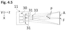
- the projection device 11 includes three light sources 30 designed as laser light sources with focusing optics (e.g. converging lenses), not shown, as well as three diffractive optical elements 31 and is set up to project an overall measurement pattern comprising three measurement patterns onto the surface 1 (and thus to illuminate the surface 1 in a structured manner).
- Each laser light source 30 illuminates the diffractive optical element 31 assigned to it with laser light in the direction of a projection axis P.
- the measurement patterns 6 generated by the irradiation of the diffractive optical elements 31 by means of light diffraction are projected in the direction of the projection axes P or, after deflection by means of the deflection mirror 15, in the direction of the projection axes P* onto partial areas of a translucent, in particular dental, surface 1 of an object to be detected.
- the lighting device B is designed as LED lighting and emits spectrally broadband light for unstructured illumination of the surface 1. It is also concentric in the shape of a ring formed around the detection axis of the detection device 12 and in particular designed so that it does not obscure the view of the detection device 12 onto the surface 1.
- the detection device 12 which can be designed, for example, as a monochrome or color camera, images of the partial areas of the surface 1 to be detected can be provided along the detection axis R or R*.
- the detection is carried out by the polarization filter 70.
- the images provided by the detection device 12 can be transmitted by means of wireless or wired data transmission via the evaluation device 120 comprising the interface unit 124 to the computer device 121 and a visual output device 122.
- the power supply is also wired via the interface unit 124;
- the energy storage 17 is required for power supply.
- Direct data transmission between the handpiece 110 and the evaluation device 120 is also possible.
- the evaluation device 120 can be designed, for example, as a PC or laptop.
- the topography of the surface can be recorded using the images of the partial areas of the surface 1 to be recorded and provided, for example, as a three-dimensional data model.
- the visual output device 122 can be designed as a screen and enables the topography of the surface to be displayed.
- the interface unit 124 includes a power supply with a mains connection; it can be designed so that it is suitable as a storage location for the handpiece.
- the power supply of the interface unit 124 can be used to charge the energy storage 17 in the handpiece 110.
- the interface unit 124 can contain a USB distributor (hub) through which the handpiece is connected to the evaluation device 120, and the power supply in the interface unit 124 can also be used to directly power the handpiece 110.
- the scanning tip 14 In order to facilitate the intraoral detection of the topography of the surface of a translucent dental object, it is expedient to design the front part of the handpiece 110, the so-called scanning tip 14, so compact that it can be inserted into the oral cavity of a patient. For this purpose, it is expedient if the scanning tip 14 does not exceed a maximum diameter D within an insertion length L. For example, within the insertion length L of 7 cm, the maximum diameter D of the scanning tip 14 should not exceed 4 cm.
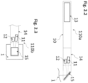
- Figure 2.2 shows a schematic representation of a further exemplary embodiment of a (compared to Figure 1 ) slim handpiece 110a of an intraoral scanner 100 according to the invention in side view, the (miniaturized) projection device 11 being arranged together with the detection device 12 in the scanning tip 14.
- Figure 2.3 shows a schematic representation of a further exemplary embodiment (compared to Figure 1 ) slim handpiece 110b of an intraoral scanner 100 according to the invention in a top view.
- the projection device 11 and the detection device 12 are arranged next to each other in the top view. In this way, a scanning tip 14 with the lowest possible (flat) cross-section can be made possible, which can improve the accessibility of regions located deep in the oral cavity.
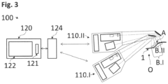
- Figure 3 The following explains how the intraoral scanner 100 according to Figure 2.1 can be used to record the topography of the surface 1 of a translucent dental object O. To increase clarity, there are: Figure 3 not alone Figure 2.1 The details of the handpiece shown are shown graphically.
- the scanning tip 14 of the handpiece 110 moves through this at a first point in time, a first position I (see handpiece 110.I), which enables the overall measurement pattern comprising the three measurement patterns to be projected onto a first partial area BI of the surface 1 (positioning the handpiece in the first position).
- the detection device 12 is set up to provide a first image, a second image and a third image of the first partial area BI, with the first measurement pattern being projected onto the surface 1 in the first image, the second measurement pattern being projected onto the surface 1 in the second image and the third measurement pattern being projected onto the surface 1 is.
- the three images can be provided (recorded) either simultaneously or sequentially.
- the exposure duration (integration time) should expediently be chosen to be as short as possible (in particular less than 20 ms) in order to minimize motion blur effects (caused by the continuous movement of the scanning tip during the recording/provision of the images).
- the three images provided in the first position I are transmitted to the evaluation device 120 by means of wireless or wired data transmission.
- the computer device 121 is set up to provide a first partial topography of the first partial area B.I by means of triangulation using the three images provided (recorded) in the first position I.
- the handpiece 110 passes through a second position II (see handpiece 110.II), which enables the overall measurement pattern comprising the three measurement patterns to be projected onto a second partial area B.II of the surface 1 ( Positioning the handpiece in the second position), the second sub-area B.II partially or completely overlapping the first sub-area BI.
- the detection device 12 provides a first image, a second image and a third image of the second sub-area B.II of the surface 1 ( record), whereby the first measurement pattern is projected onto surface 1 in the first image, the second measurement pattern in the second image and the third measurement pattern in the third image.
- the Computer device 121 provides a second partial topography of the second partial area by means of triangulation using the three images provided (recorded) in the second position II.
- the computer device 121 is set up to create an (overall) topography of (the first and second sub-regions) by partially superimposing the first sub-topography (of the first sub-area B.I of the surface) and the second sub-topography (of the second sub-area B.II of the surface). to provide part of the surface (comprising the surface).
- the working plane A is the plane on which the optical components of the projection device 11, detection device 12 and lighting device B are designed for optimal function.
- the design concerns, for example, the focus distances of the projection device and detection device, the spatial position of the projection axis and detection axis relative to one another or the beam shaping of the lighting device.
- a surface 1 can be recorded in the best possible quality if it lies in the working plane A. If, as is unavoidable in practice, it lies outside the working plane A, but within the permissible working area, it can still be recorded with a quality suitable for the application, since the optical components are designed to maintain the function within the working area (for example with regard to the depth of field of projection images). and detection optics).
- An application-appropriate position of the working plane A would, for example, be at a distance of approx. 5 mm from the surface of the scanning tip (outside the scanning tip).
- the working area can, for example, extend from the working plane in the direction of the scanning tip to the surface of the scanning tip, and in the opposite direction up to a distance of approximately 20 mm.
- the Figures 4.1 and 4.2 show a schematic representation of a projection device 11 of an exemplary embodiment of an intraoral scanner according to the invention in a side view ( Figure 4.1 ) or in plan view ( Figure 4.2 ).
- the projection device 11 includes three light sources 30 designed as laser light sources and three diffractive optical elements (DOEs) 31.
- DOEs diffractive optical elements
- the light sources 30 emit light beams focused in the direction of the projection axes P onto the working plane A, which are selectively divided and redirected into a large number of beams by the diffractive optical elements 31 in accordance with the pattern definitions by means of light diffraction, whereby three focused measurement patterns (each in the direction of the respective projection axis P) can be projected.
- One of the three diffractive optical elements 31 is assigned to the light sources 30, each of which generates an assigned measurement pattern (stored therein).
- the light-diffractive effect of the diffractive optical elements 31, i.e. the generation of the measurement pattern under incident light, is brought about by diffraction structures 36 arranged on or in the diffractive optical element, the diffraction structures 36 in the present exemplary embodiment being designed as flat diffraction structures (diffraction-active surfaces).
- the three planar diffraction structures 36 of the diffractive optical elements 31 are arranged in a common plane on a common one-piece (DOE) substrate 31S. The three diffractive optical elements 31 are therefore made in one piece.
- the measurement patterns are projected at respective opening angles 33, which correspond to the minimum opening angles at which an area on the working plane A defined by the projection width W is just covered by all measurement patterns.
- Fig. 4.3 shows three diffractive optical elements 31 designed in one piece on a common substrate 31S, each with a diffraction structure 36 (diffraction-active surface) that is individual for the respective measurement pattern in a frontal view.
- the projection device 11 further comprises a first device V1 and a second device V2 for adjustment and a device for reducing speckle V3.
- the diffractive optical elements 31, 31S can be moved linearly in translation (moveable by machine operation).
- light emitted by the light source 30 is not focused on the working plane A.
- the focusing on the working plane A is instead produced by the DOEs 31, 31S, which means that corresponding optics (focusing optical component) can be saved.
- Figure 4.4 shows schematically the through one of the three diffractive optical elements 31 (according to the Figures 4.1 to 4.3 ) on a surface 1 (arranged in the working plane A) (undistorted) measurement pattern 6, which has measurement lines 9 parallel to one another as measuring elements and is arranged symmetrically around the measurement pattern center 37.
- the measurement pattern projected onto the surface 1 is also referred to as measurement pattern projection, or projection of the measurement pattern onto the surface.
- Figure 4.5 shows a schematic representation of a projection device of a further exemplary embodiment of an intraoral scanner according to the invention in a top view, comprising three light sources 30, each designed as laser light sources with collimation optics, and three diffractive optical elements 31 (DOEs).
- the light sources 30 are aligned (oriented) in such a way that their projection axes P converge on a common point F the working plane A.
- the foci of the light sources 30 are adjusted to this common point F on the working plane A by means of the collimation optics.
- the focusing can also advantageously be carried out by the DOEs 31, which means that the collimation optics can be saved.
- the diffraction structures 36 (diffraction-active surfaces) of the DOEs are in the exemplary embodiment according to Figure 4.5 each oriented perpendicular to the projection axes of the light sources and designed as separate, individual DOEs, but can alternatively also have a common orientation and be arranged on a common, one-piece DOE substrate (corresponding to 31S).
- the latter arrangement requires an appropriate interpretation (design) of the diffraction-active surfaces 36 for laser beams incident obliquely (ie not perpendicular to the DOE surface).
- An advantage of the in Figure 4.5 The illustrated embodiment is that a jointly covered area of the measurement pattern projections can be achieved with smaller opening angles 33 of the individual pattern projections than would be the case with parallel projection axes P, which leads to higher light efficiency.
- Figures 5.1 and 5.2 show schematic sections of a projection device 11 of intraoral scanners 100 according to the invention. For reasons of clarity, the illustration is limited to a single light source 30, a single diffractive optical element 31 and a single pattern projection.
- Figure 5.1a shows a light source 30 with converging lens optics 40 (eg a spherical or aspherical lens, optionally having astigmatism), which is set up to focus light emitted by the light source 30 onto a working plane A.
- a diffractive optical element 31 generates a measurement pattern projection (or a measurement pattern) by means of light diffraction.
- the representation of Figure 5.1a is in top view; Figure 5.1b shows the same embodiment in side view.
- a diffractive pattern projection there is usually a portion of the incident light that is not diffracted - the so-called "zero order", "0th order” or "0th diffraction order".
- the zeroth order can typically be reduced to a proportion of approximately 0.1-1% of the incident light. Such a proportion usually results in the zeroth order still producing the highest (light) intensity in the projected measurement pattern.
- the zeroth order is usually found in the form of a bright spot in the center of the projected measurement pattern. Since it is typically not part of the desired measurement pattern projection, it is also usually a source of interference, for example when interpreting the projected measurement pattern using image processing.
- the light beam formed by the converging lens optics and not focused on the working plane A strikes a light beam in comparison to the exemplary embodiment of Figure 5.1 added astigmatic optics (lens) 41, which focuses light predominantly in one dimension onto the working plane.
- the astigmatic optics 41 is designed here as a cylindrical lens optics, with the cylinder axis parallel to the in Figure 5.2 X axis shown.
- the light focused in one dimension hits a DOE 31, which generates a (measuring) pattern projection, in particular a measuring pattern comprising measuring lines, by means of light diffraction.
- the measuring lines are parallel to the cylinder axis Cylindrical lens optics (as well as the X axis).
- the pattern projection on the working plane A (which is perpendicular to the Z-axis) is focused in the direction of the Y-axis and unfocused in the direction of the X-axis.
- the zeroth order (light) intensity is effectively reduced by this embodiment because the incident light is focused in only one direction (dimension) and is collimated or defocused in the other direction. As a result, the zeroth order does not produce a focused point of high light intensity in the measurement pattern center of the pattern projection, but rather a line of reduced light intensity.
- the (light) intensity of the line is inversely proportional to its length, which in turn is proportional to the defocusing of the incident light in the X-axis. Since the line lies along the measurement lines of measurement patterns according to the invention, it itself does not cause any defocusing of the measurement pattern.
- a single lens or a lens system with defined astigmatism can also advantageously be used for each light source.
- a projection device 11 can effectively reduce the intensity of the zeroth order by generating a focal line instead of a focal point on the working plane A, which runs along the direction of the measurement lines of the measurement pattern.
- Figure 6.1 shows a schematic representation of a projection device 11 of a further exemplary embodiment of an intraoral scanner according to the invention in a top view, which advantageously allows the projection of several measurement patterns by means of light diffraction in a cost-efficient and compact manner.
- a light source 30 emits a light beam which is split and redirected by a combination of beam splitters 50 and mirrors 52.
- all three outgoing beams have the same photometric performance.
- this can be achieved by a first beam splitter 50 with approximately 33.3% transmission and approximately 66.7% reflection, a second beam splitter 50 with approximately 50.0% transmission and reflection, and a mirror 52.
- the photometric performance can be particularly advantageously varied by means of the division ratios of the beam splitters so that the measurement lines in all measurement patterns have the same intensity .
- Other methods known in the prior art such as prisms or diffractive beam splitting methods, can also be used for division and deflection.
- the incident beam is divided into three outgoing beams; Smaller or higher divisions can also be achieved using appropriate means known in the prior art.
- FIG. 6.2 shows a schematic representation of an advantageous spatial light modulator 53, which contains several optically modulated segments 54, the number of which corresponds at least to the number of incident light rays. As in Figure 6.2 shown, these optically modulable segments 54 can be arranged on a single (one-piece) component, or can be formed from several separate components.
- a projection control device 51 switches (controls) the light emission of the light source 30 and the state of the spatial light modulator 53 for the respective beam path, and thus the illumination of a respectively assigned DOE 31.
- the three DOEs 31 are advantageous here as a one-piece, common DOE substrate 31S with multiple separate diffraction structures 36, whereby several individual DOEs or substrates can also be used.
- the light beam emitted by the light source 30 can be essentially collimated (for example by means of a converging lens optics, not shown), that is, the emitted light beams have a minimized divergence.
- the collimated light beams each strike a focusing optic arranged between the beam splitter 50 or mirror 52 and DOE 31, which focuses incident light beams onto the working plane A.
- a focusing optic that has an astigmatism that focuses incident steel in the direction of the Y-axis onto the working plane A, and does not focus on the working plane A in the direction of the X-axis.
- the focusing optics can be as in Fig. 6.1 shown can advantageously be listed as a one-piece astigmatic optics 41 (for example a cylindrical lens whose cylinder axis runs parallel to the X-axis), but individual astigmatic optics or individual non-astigmatic optics are also possible.
- Light-focusing DOEs can also be used instead of the focusing optics.
- Figure 7 shows representations of measurement patterns of an exemplary embodiment of an intraoral scanner according to the invention, as well as their spatial orientation and symmetry.
- the three measurement patterns 6 shown form an overall measurement pattern and each include a plurality of measurement lines 9, which run parallel to the X-axis.
- Figure 7a represents a first measurement pattern
- Figure 7b a second measurement pattern
- Figure 7c represents a third measurement pattern (of the three measurement patterns 9).
- the measurement patterns 6 projected onto a surface 1 would theoretically appear undistorted in this way, if they were each viewed from a detection axis R coinciding with the respective projection axis P (which is not the case in the present invention).
- the coordinate system shown here corresponds to the coordinate system of previous figures.
- the measuring lines 9 are arranged at possible measuring line positions 9P.
- the possible measuring line positions 9P correspond to a grid with a constant measuring line period MP.
- a measuring line 9 shown on a possible measuring line position 9P is also referred to as a shown measuring line 9P_D.
- a possible measuring line position 9P on which no measuring line is arranged is referred to as a non-illustrated measuring line 9P_ND.
- the combination of shown measuring lines 9P_D and non-shown measuring lines 9P_ND within a group G corresponds to a symbol assigned (to the possible measuring line position 9P).
- Figure 7 not all shown, but only selected measuring lines 9, possible measuring line positions 9P, shown measuring lines 9P_D, not shown measuring lines 9P_ND or groups G are provided with a corresponding reference number.
- the measurement patterns 6 are point-symmetrical about a respective measurement pattern center 37 and can therefore be generated using binary DOEs. To illustrate the symmetry, a horizontal axis of symmetry 62 and vertical axes of symmetry 63 in Figure 7 drawn.
- the measurement patterns 6 are preferably designed in such a way that the measurement pattern center 37 and thus the zeroth diffraction order lies on a measurement line 9. If it were not on a measuring line, depending on the exemplary embodiment, it would create a point or a line in the middle of the measuring pattern, which would not be part of the desired pattern projection.
- Figure 8 shows a schematic representation of an exemplary embodiment of an intraoral scanner according to the invention, comprising a projection device 11 and a Detection device 12, a deflection mirror 15, and a transmissive linear polarization filter 70 with a polarization direction of detection according to arrow 72.
- the projection device 11 has three light sources 30 designed as laser light sources with a natural linear polarization direction of light emission according to arrows 71 of the emitted light, and three Diffractive optical elements (DOE) 31 designed as a one-piece DOE substrate 31S, each with a diffraction structure (or diffraction-active surface) 36.
- DOE Diffractive optical elements
- the light sources 30 sequentially or simultaneously illuminate the diffractive optical elements 31 or diffraction structures 36 assigned to them and, by means of light diffraction, generate respective measurement patterns 6 of structured lighting (stored there).
- the measurement patterns 6 are reflected by the deflection mirror 15 onto a surface 1 of an object to be detected.
- the detection device 12 detects the measurement patterns 6 projected onto the surface 1 via the deflection mirror 15.
- the light sources 30 and the transmissive polarization filter 70 are aligned with one another so that they have a common polarization direction.
- the light sources 30 are aligned rotationally about the respective projection axes P;
- the polarization filter 70 is aligned rotationally about the detection axis R.
- the polarization direction is usually correlated with housing features. Accordingly, the mounting device for the light sources can be designed so that it can only be fitted in the correct polarization direction. The thus ensured common polarization direction of the light sources is retained during the projection of the structured lighting by means of light diffraction, as well as during the two-fold deflection (projection and detection) by the deflection mirror 15.
- the illustrated common polarization direction of the light sources 30 and the polarization filter 70 is given as an example. What is crucial for an effective design is that the components have a common polarization direction.
- the polarization filter 70 shown is designed as a transmissive polarization filter.
Landscapes
- Health & Medical Sciences (AREA)
- Physics & Mathematics (AREA)
- Optics & Photonics (AREA)
- General Physics & Mathematics (AREA)
- Public Health (AREA)
- Oral & Maxillofacial Surgery (AREA)
- Dentistry (AREA)
- Epidemiology (AREA)
- Life Sciences & Earth Sciences (AREA)
- Animal Behavior & Ethology (AREA)
- General Health & Medical Sciences (AREA)
- Veterinary Medicine (AREA)
- Computer Vision & Pattern Recognition (AREA)
- Engineering & Computer Science (AREA)
- Dental Tools And Instruments Or Auxiliary Dental Instruments (AREA)
- Length Measuring Devices By Optical Means (AREA)
Claims (19)
- Procédé de détection de la topographie de la surface (1) d'un objet (O) translucide, notamment dentaire, comportant les étapes consistant à :- détecter une première topographie partielle d'une première zone partielle (B.I) de la surface (1) et d'une deuxième topographie partielle d'une première zone partielle (B.I) chevauchant au moins partiellement la deuxième zone partielle (B. II) de la surface (1), dans lequel la détection des topographies partielles des sous-zones (B.I, B.II) de la surface (1) a lieu respectivement- en projetant un motif de mesure global sur la zone partielle respective (B.I, B.II) de la surface (1) de l'objet translucide (0) au moyen d'un dispositif de projection (11), dans lequel- le dispositif de projection (11) comporte au moins une source lumineuse (30) et au moins deux éléments optiques diffractifs (31),- le motif de mesure total comprend au moins deux motifs de mesure différents (6),- le motif de mesure (6) peut être projeté sur la surface (1) et présentent respectivement une pluralité de lignes de mesure mutuellement parallèles (9),- l'un des éléments optiques diffractifs (31) est associé au motif de mesure (6), au moyen duquel les lignes de mesure (9) peuvent être générées par diffraction de la lumière,- la au moins une source lumineuse (30) illumine les éléments optiques diffractifs (31) avec une lumière polarisée linéairement dans une direction de polarisation (71), et entre la surface (1) et le dispositif de détection (12) est agencé un filtre de polarisation linéaire (70), dont la direction de transmission (72) correspond à la direction de polarisation (71), et- fournissant une première image et une deuxième image de la sous-zone respective (B.I, B.II) de la surface (1) au moyen d'un dispositif de détection (12), dans lequel dans la première image un premier des au moins deux motifs de mesure (6) est projeté sur la zone partielle respective (B.I, B.II) de la surface (1) et dans la deuxième image un deuxième des au moins deux modèles de mesure (6) est projeté sur la zone partielle respective (B.I, B.II) de la surface (1), et- détectant la topographie partielle respective de la surface partielle (B.I, B.II) de la surface (1) respectivement au moyen d'une triangulation à l'aide de la première image respective et/ou de la deuxième image respective,- détecter la topographie de la surface (1) par superposition au moins partielle de la première topographie partielle et de la deuxième topographie partielle de la surface (1).
- Procédé selon la revendication 1, caractérisé en ce que le filtre de polarisation (70) polarisant agit uniquement dans le spectre d'émission de la au moins une source lumineuse (30) et le spectre d'émission restant est neutre.
- Procédé selon une quelconque des revendications précédentes, caractérisé en ce que la projection du motif de mesure global sur la zone partielle respective (BI, B.II) de la surface (1) de l'objet translucide (O) comprend de :
réduire du chatoiement au moyen d'un dispositif de réduction du chatoiement (V3), éventuellement en déplaçant, notamment en translation, au moins un des éléments optiques diffractifs (31) lors de la projection du motif de mesure global. - Procédé selon une quelconque des revendications précédentes, caractérisé en ce que les lignes de mesure (9) sont calibrées à l'aide de surfaces algébriques et éventuellement la triangulation s'effectue à l'aide de ces surfaces algébriques.
- Procédé selon une quelconque des revendications précédentes, caractérisé en ce que le procédé comprend en outre de :
créer un éclairage déstructuré en surface (1) de l'objet (O) avec une intensité uniformément répartie en utilisant un dispositif d'éclairage (B), dans lequel éventuellement l'éclairage non structuré comprend une lumière rouge, verte, bleue, blanche, ultraviolette, proche infrarouge ou infrarouge ou une combinaison de celles-ci. - Procédé selon une quelconque des revendications précédentes, caractérisé en ce que le premier motif de mesure (6) est projeté dans un premier spectre de longueurs d'onde et le deuxième motif de mesure (6) est projeté dans un deuxième spectre de longueurs d'onde, en particulier simultanément, et
le dispositif de détection (12) est agencé d'une manière spectralement sélective telle que la première image au moyen d'une superposition capturant la lumière du premier spectre de longueur d'onde et la deuxième image soit fournie en capturant principalement la lumière du deuxième spectre de longueur d'onde. - Procédé selon une des revendications précédentes, caractérisé en ce que, le premier motif de mesure (6) est projeté dans un premier état de polarisation ou dans une première direction de polarisation et le deuxième motif de mesure (6) est projeté dans un deuxième état de polarisation ou dans une deuxième direction de polarisation, en particulier simultanément, et
le dispositif de détection (12) est configuré pour être sélectif en polarisation ou sensible à la polarisation de telle manière que la première image soit capturée en capturant principalement la lumière de la première direction de polarisation ou du premier état de polarisation et la deuxième image est fournie par détection prédominante de la lumière de la deuxième direction de polarisation ou du deuxième état de polarisation. - Scanner intra-oral (100) pour détecter la topographie de la surface (1) d'un objet translucide, notamment dentaire (O) dans un procédé selon une quelconque des revendications précédentes, comprenant un dispositif de projection (11), un dispositif de détection (12) et un avec le dispositif de projection (11) et le dispositif de détection (12) fonctionnellement connecté au dispositif informatique (121),- dans lequel le dispositif de projection (11) comporte au moins une source lumineuse (30) et au moins deux éléments optiques diffractifs (31) inclut et est conçu pour projeter un schéma de mesure global sur des zones partielles (B.I, B.II) de la surface (1) de l'objet translucide (O),le motif de mesure global comprend au moins deux motifs de mesure différents (6),les motifs de mesure (6) peuvent être projetés chacun sur la surface (1) et présentent chacun plusieurs lignes de mesure (9) parallèles entre elles,aux motifs de mesure (6) est associé un des éléments optiques diffractifs (31) au moyen duquel les lignes de mesure (9) peuvent être générées par diffraction de la lumière, etla au moins une source lumineuse (30) illumine les éléments optiques diffractifs (31) avec une lumière polarisée linéairement dans une direction de polarisation (71), et entre la surface (1) et le dispositif de détection (12) un filtre de polarisation linéaire (70) est disposé, dont la direction de transmission (72) correspond à la direction de polarisation (71),- dans lequel le dispositif de détection (12) est configuré pour fournir une première image et une deuxième image de la sous-zone respective (B.I, B.II) pour fournir la surface (1), et dans la première image un premier des au moins deux motifs de mesure (6) est projeté sur la zone partielle respective (B.I, B.II) de la surface (1) et dans la deuxième image un deuxième des au moins deux motifs de mesure (6) est projeté sur la zone partielle respective (B.I, B.II) de la surface (1),- dans lequel le dispositif informatique (121) est configuré pourdétecter une première topographie partielle de la première zone partielle (B.I) de la surface (1) et une deuxième topographie partielle de la deuxième zone partielle (B.II) de la surface (1), respectivement au moyen de la triangulation en utilisant la première image respective et/ou la deuxième image respective, etdétecter la topographie de la surface (1) en superposant au moins partiellement la première topographie partielle et la deuxième topographie partielle de la surface (1).
- Scanner intra-oral (100) selon la revendication 8, caractérisé en ce que les éléments optiques diffractifs (31) sont disposés sur un substrat commun (31S), notamment les structures de diffraction (36) des éléments optiques diffractifs (31) sont agencées dans un plan commun.
- Scanner intra-oral (100) selon une quelconque des revendications 8 ou 9, caractérisé en ce qu'au moins un des motifs de mesure (6) est à symétrie ponctuelle par rapport à un centre de motif de mesure (37) et éventuellement l'élément optique diffractif associé (31) est conçu comme un élément optique diffractif binaire.
- Scanner intra-oral (100) selon une des revendications 8 à 10, caractérisé en ce que les motifs de mesure (6) peuvent chacun être projetés sur la surface (1) en direction d'un axe de projection (P) et des axes de projection (P) sont disposés dans un plan d'axe de projection commun, qui est parallèle à la direction de lignes de mesure (9) et qu'optionnellement au moins un point central (37) du motif de mesure d'un motif de mesure (6) est disposé dans le plan d'axe de projection commun.
- Scanner intra-oral (100) selon une quelconque des revendications 8 à 11, caractérisé en ce que le dispositif de projection (11) comprend un premier dispositif de réglage (V1) d'une position d'au moins un axe de projection (P) et/ou un deuxième dispositif de réglage (V2), dans lequel au moyen du deuxième dispositif de réglage (V2)- une distance entre un des éléments optiques diffractifs (31) et la au moins une source lumineuse (30) peut être changée ou- une distance entre une lentille et la au moins une source lumineuse (30) peut être changée.
- Scanner intra-oral (100) selon une quelconque des revendications 8 à 12, caractérisé en ce que la projection du motif de mesure (6) s'effectue à différents angles d'ouverture (33).
- Scanner intra-oral (100) selon une quelconque des revendications 8 à 13, caractérisé en ce que le dispositif de projection (11) comprend un dispositif de réduction du chatoiement (V3) et éventuellement au moins un des éléments optiques diffractifs (31), notamment en translation, peut être déplacé lors de la projection du motif de mesure global.
- Scanner intra-oral (100) selon une quelconque des revendications 8 à 14, caractérisé en ce que le dispositif de projection (11) comprend au moins une lentille astigmate.
- Scanner intra-oral (100) selon une des revendications 8 à 15, caractérisé en ce qu'au moins un des éléments optiques diffractifs (31) a un effet de focalisation de la lumière.
- Scanner intra-oral (100) selon une quelconque des revendications 8 à 16, caractérisé en ce que le dispositif de projection (11) comprend au moins un séparateur de faisceau (50) et au moins un modulateur spatial de lumière (53).
- Scanner intra-oral (100) selon une des revendications 8 à 17, caractérisé en ce que le dispositif de projection (11) comprend un dispositif d'éclairage (B) pour générer un éclairage non structuré sur la surface (1) de l'objet (0) avec une intensité uniformément répartie et éventuellement l'éclairage rouge, vert, bleu, blanc, ultraviolet, proche lumière infrarouge ou infrarouge ou une combinaison de celles-ci.
- Scanner intra-oral (100) selon une quelconque des revendications 8 à 18, caractérisé en ce que la au moins une source lumineuse (30) est réalisée sous forme de source lumineuse laser,et la source de lumière laser est monomode dans une première dimension et multimode dans une deuxième dimension, dans lequel la deuxième dimension est alignée parallèlement ou perpendiculairement à la direction des lignes de mesure (9),et/ou au moins un paramètre de fonctionnement de la source de lumière laser est régulé et/ou le au moins un paramètre de fonctionnement peut être modulé avec une fréquence dans la plage de 1 à 1000 MHz.
Applications Claiming Priority (2)
| Application Number | Priority Date | Filing Date | Title |
|---|---|---|---|
| DE102020133627.6A DE102020133627A1 (de) | 2020-12-15 | 2020-12-15 | Verfahren und Intraoralscanner zum Erfassen der Topographie der Oberfläche eines transluzenten, insbesondere dentalen, Objektes |
| PCT/EP2021/084571 WO2022128621A1 (fr) | 2020-12-15 | 2021-12-07 | Procédé et scanner intrabuccaux pour détection de topographie de surface d'un objet translucide, en particulier un objet dentaire |
Publications (2)
| Publication Number | Publication Date |
|---|---|
| EP4100694A1 EP4100694A1 (fr) | 2022-12-14 |
| EP4100694B1 true EP4100694B1 (fr) | 2023-09-27 |
Family
ID=79259401
Family Applications (1)
| Application Number | Title | Priority Date | Filing Date |
|---|---|---|---|
| EP21836376.0A Active EP4100694B1 (fr) | 2020-12-15 | 2021-12-07 | Procédé et scanner intrabuccaux pour détection de topographie de surface d'un objet translucide, en particulier un objet dentaire |
Country Status (5)
| Country | Link |
|---|---|
| US (1) | US12433724B2 (fr) |
| EP (1) | EP4100694B1 (fr) |
| CN (1) | CN116783452A (fr) |
| DE (1) | DE102020133627A1 (fr) |
| WO (1) | WO2022128621A1 (fr) |
Families Citing this family (5)
| Publication number | Priority date | Publication date | Assignee | Title |
|---|---|---|---|---|
| KR102752944B1 (ko) * | 2021-12-28 | 2025-01-14 | 주식회사 메디트 | 3차원 스캐너용 단일 패턴 쉬프트 투사 광학계 |
| WO2024200351A1 (fr) * | 2023-03-24 | 2024-10-03 | 3Shape A/S | Système de scanner extrabuccal |
| CN116880118A (zh) * | 2023-06-25 | 2023-10-13 | 中国科学院半导体研究所 | 条形结构光投影装置 |
| TWI880395B (zh) * | 2023-10-13 | 2025-04-11 | 佳世達科技股份有限公司 | 照明裝置 |
| DE102024200967B4 (de) * | 2024-02-02 | 2026-02-19 | Carl Zeiss Meditec Ag | Verfahren und System zur Erzeugung eines dreidimensionalen Abbilds zumindest eines Teilabschnitts einer Zahnreihe und Computerprogramm |
Family Cites Families (23)
| Publication number | Priority date | Publication date | Assignee | Title |
|---|---|---|---|---|
| DE19636354A1 (de) | 1996-09-02 | 1998-03-05 | Ruedger Dipl Ing Rubbert | Verfahren und Vorrichtung zur Durchführung von optischen Aufnahmen |
| DE102007054906B4 (de) | 2007-11-15 | 2011-07-28 | Sirona Dental Systems GmbH, 64625 | Verfahren zur optischen Vermessung der dreidimensionalen Geometrie von Objekten |
| DE102007054907A1 (de) | 2007-11-15 | 2009-05-28 | Sirona Dental Systems Gmbh | Verfahren zur optischen Vermessung von Objekten unter Verwendung eines Triangulationsverfahrens |
| DE102008047816B4 (de) | 2008-09-18 | 2011-08-25 | Steinbichler Optotechnik GmbH, 83115 | Vorrichtung zur Ermittlung der 3D-Koordinaten eines Objekts, insbesondere eines Zahns |
| CA2763826C (fr) * | 2009-06-17 | 2020-04-07 | 3Shape A/S | Appareil d'exploration a focalisation |
| DE102011077564B4 (de) | 2011-06-15 | 2016-08-25 | Sirona Dental Systems Gmbh | Verfahren zur optischen dreidimensionalen Vermessung eines dentalen Objekts |
| DE102011082349B3 (de) | 2011-09-08 | 2013-01-10 | Sirona Dental Systems Gmbh | Verfahren und Vorrichtung zur dreidimensionalen konfokalen Vermessung |
| DE102012102580A1 (de) | 2012-03-26 | 2013-09-26 | Degudent Gmbh | Verfahren zum Messen eines Objektes sowie Intraoral-Scanner |
| JP6430934B2 (ja) * | 2012-06-27 | 2018-11-28 | 3シェイプ アー/エス | 蛍光を測定する口腔内3dスキャナ |
| DE102012214473B4 (de) | 2012-08-14 | 2022-01-13 | Sirona Dental Systems Gmbh | Verfahren zur Vermessung eines dentalen Objekts mittels einer dentalen Kamera |
| DE102012220048B4 (de) | 2012-11-02 | 2018-09-20 | Sirona Dental Systems Gmbh | Kalibrierungsvorrichtung und Verfahren zur Kalibrierung einer dentalen Kamera |
| AU2014211981A1 (en) | 2013-02-04 | 2015-08-20 | D4D Technologies, Llc | Intra-oral scanning device with illumination frames interspersed with image frames |
| DE102014212231A1 (de) * | 2014-06-25 | 2015-12-31 | Dental Direkt GmbH | Koordinatenmessgerät |
| US9660418B2 (en) * | 2014-08-27 | 2017-05-23 | Align Technology, Inc. | VCSEL based low coherence emitter for confocal 3D scanner |
| DE102015205187A1 (de) * | 2015-03-23 | 2016-09-29 | Siemens Aktiengesellschaft | Verfahren und Vorrichtung zur Projektion von Linienmustersequenzen |
| US10507087B2 (en) * | 2016-07-27 | 2019-12-17 | Align Technology, Inc. | Methods and apparatuses for forming a three-dimensional volumetric model of a subject's teeth |
| JP6319395B2 (ja) * | 2016-10-14 | 2018-05-09 | オムロン株式会社 | 3次元測定装置および3次元測定方法 |
| EP3529553A4 (fr) | 2016-10-18 | 2020-06-17 | Dentlytec G.P.L. Ltd. | Motifs de balayage intra-oral |
| WO2019032923A2 (fr) | 2017-08-10 | 2019-02-14 | D4D Technologies, Llc | Dispositif de balayage intraoral |
| JP7427595B2 (ja) * | 2018-01-26 | 2024-02-05 | アライン テクノロジー, インコーポレイテッド | 診断の為の口腔内のスキャン及び追跡 |
| JP7193304B2 (ja) * | 2018-03-19 | 2022-12-20 | ソニーセミコンダクタソリューションズ株式会社 | 光源システム、光学回折素子製造方法、および測距システム、ならびに光学回折素子 |
| US11096765B2 (en) * | 2018-06-22 | 2021-08-24 | Align Technology, Inc. | Light field intraoral 3D scanner with structured light illumination |
| WO2020102658A2 (fr) | 2018-11-16 | 2020-05-22 | Carestream Dental Llc | Système de projection laser |
-
2020
- 2020-12-15 DE DE102020133627.6A patent/DE102020133627A1/de not_active Withdrawn
-
2021
- 2021-12-07 WO PCT/EP2021/084571 patent/WO2022128621A1/fr not_active Ceased
- 2021-12-07 EP EP21836376.0A patent/EP4100694B1/fr active Active
- 2021-12-07 CN CN202180092626.8A patent/CN116783452A/zh active Pending
-
2023
- 2023-06-13 US US18/209,199 patent/US12433724B2/en active Active
Also Published As
| Publication number | Publication date |
|---|---|
| US20230320825A1 (en) | 2023-10-12 |
| WO2022128621A1 (fr) | 2022-06-23 |
| DE102020133627A1 (de) | 2022-06-15 |
| EP4100694A1 (fr) | 2022-12-14 |
| US12433724B2 (en) | 2025-10-07 |
| CN116783452A (zh) | 2023-09-19 |
Similar Documents
| Publication | Publication Date | Title |
|---|---|---|
| EP4100694B1 (fr) | Procédé et scanner intrabuccaux pour détection de topographie de surface d'un objet translucide, en particulier un objet dentaire | |
| EP3298344B1 (fr) | Procédé et caméra pour la mesure tridimensionnelle d'un objet dentaire | |
| EP2398379B1 (fr) | Caméra dentaire tenue manuellement et procédé de relevé optique tridimensionnel | |
| DE102006007170B4 (de) | Verfahren und Anordnung zur schnellen und robusten chromatisch konfokalen 3D-Messtechnik | |
| DE102008017481B4 (de) | Vorrichtung und Verfahren zur optischen 3D-Vermessung und zur Farbmessung | |
| DE102008040947B4 (de) | 3D-Dentalkamera zur Erfassung von Oberflächenstrukturen eines Messobjekts mittels Triangulation | |
| EP3298345B1 (fr) | Caméra et procédé pour réaliser une mesure en 3d et une mesure de couleur d'un objet dentaire | |
| DE102011082349B3 (de) | Verfahren und Vorrichtung zur dreidimensionalen konfokalen Vermessung | |
| DE102007019267A1 (de) | Messanordnung sowie Verfahren zum dreidimensionalen Messen eines Objekts | |
| WO2016066374A1 (fr) | Dispositif d'éclairage avec un agencement de conversion de longueurs d'onde | |
| EP1757902B1 (fr) | Procédé et dispositif pour mesurer la forme d'un objet dentaire | |
| EP3298346A1 (fr) | Dispositif pour réaliser une mesure en 3d d'un objet | |
| EP1971820A1 (fr) | Etablissement d'une image de distance | |
| DE102008002730A1 (de) | Verfahren und Vorrichtung zur 3D-Rekonstruktion | |
| EP2095184A2 (fr) | Dispositif de projection ayant une propriété de projection améliorée | |
| DE10118463A1 (de) | Verfahren und Anordnung zur tiefenaufgelösten optischen Erfassung einer Probe | |
| DE102012001307A1 (de) | Verfahren und Vorrichtung zur 3D-Messung von Objekten, insbesondere unter hinderlichen Lichtverhältnissen | |
| WO2024047253A1 (fr) | Dispositif et procédé pour réaliser un balayage intrabuccal | |
| DE102012011202A1 (de) | Projektor und Verfahren zum Erzeugen eines Bildes | |
| DE102016109131B4 (de) | Verfahren zur dreidimensionalen Erfassung eines Objekts | |
| AT526735B1 (de) | Messsystem zur Erzeugung von 3D-Bildern | |
| DE102020127894B4 (de) | Verfahren und Vorrichtung zur optischen dreidimensionalen Vermessung von Objekten | |
| DE102023120240B4 (de) | Aufnahmevorrichtung zum Erzeugen einer 3D-Aufnahme eines dreidimensionalen Objekts und Verfahren | |
| WO2025181023A1 (fr) | Appareil d'éclairage pour un dispositif d'imagerie médicale, en particulier un endoscope, un exoscope et/ou un microscope | |
| WO2017178528A1 (fr) | Microscope comportant des groupes d'émetteurs de lumière pour l'éclairage et procédé de microscopie |
Legal Events
| Date | Code | Title | Description |
|---|---|---|---|
| STAA | Information on the status of an ep patent application or granted ep patent |
Free format text: STATUS: UNKNOWN |
|
| STAA | Information on the status of an ep patent application or granted ep patent |
Free format text: STATUS: THE INTERNATIONAL PUBLICATION HAS BEEN MADE |
|
| PUAI | Public reference made under article 153(3) epc to a published international application that has entered the european phase |
Free format text: ORIGINAL CODE: 0009012 |
|
| STAA | Information on the status of an ep patent application or granted ep patent |
Free format text: STATUS: REQUEST FOR EXAMINATION WAS MADE |
|
| 17P | Request for examination filed |
Effective date: 20220908 |
|
| AK | Designated contracting states |
Kind code of ref document: A1 Designated state(s): AL AT BE BG CH CY CZ DE DK EE ES FI FR GB GR HR HU IE IS IT LI LT LU LV MC MK MT NL NO PL PT RO RS SE SI SK SM TR |
|
| GRAP | Despatch of communication of intention to grant a patent |
Free format text: ORIGINAL CODE: EPIDOSNIGR1 |
|
| STAA | Information on the status of an ep patent application or granted ep patent |
Free format text: STATUS: GRANT OF PATENT IS INTENDED |
|
| INTG | Intention to grant announced |
Effective date: 20230208 |
|
| GRAS | Grant fee paid |
Free format text: ORIGINAL CODE: EPIDOSNIGR3 |
|
| GRAA | (expected) grant |
Free format text: ORIGINAL CODE: 0009210 |
|
| STAA | Information on the status of an ep patent application or granted ep patent |
Free format text: STATUS: THE PATENT HAS BEEN GRANTED |
|
| DAV | Request for validation of the european patent (deleted) | ||
| DAX | Request for extension of the european patent (deleted) | ||
| AK | Designated contracting states |
Kind code of ref document: B1 Designated state(s): AL AT BE BG CH CY CZ DE DK EE ES FI FR GB GR HR HU IE IS IT LI LT LU LV MC MK MT NL NO PL PT RO RS SE SI SK SM TR |
|
| REG | Reference to a national code |
Ref country code: CH Ref legal event code: EP |
|
| REG | Reference to a national code |
Ref country code: DE Ref legal event code: R096 Ref document number: 502021001104 Country of ref document: DE |
|
| REG | Reference to a national code |
Ref country code: IE Ref legal event code: FG4D Free format text: LANGUAGE OF EP DOCUMENT: GERMAN |
|
| PUAC | Information related to the publication of a b1 document modified or deleted |
Free format text: ORIGINAL CODE: 0009299EPPU |
|
| STAA | Information on the status of an ep patent application or granted ep patent |
Free format text: STATUS: GRANT OF PATENT IS INTENDED |
|
| GRAA | (expected) grant |
Free format text: ORIGINAL CODE: 0009210 |
|
| STAA | Information on the status of an ep patent application or granted ep patent |
Free format text: STATUS: THE PATENT HAS BEEN GRANTED |
|
| REG | Reference to a national code |
Ref country code: CH Ref legal event code: PK Free format text: DIE ERTEILUNG WURDE VOM EPA WIDERRUFEN. |
|
| DB1 | Publication of patent cancelled |
Effective date: 20230818 |
|
| AK | Designated contracting states |
Kind code of ref document: B1 Designated state(s): AL AT BE BG CH CY CZ DE DK EE ES FI FR GB GR HR HU IE IS IT LI LT LU LV MC MK MT NL NO PL PT RO RS SE SI SK SM TR |
|
| REG | Reference to a national code |
Ref country code: CH Ref legal event code: EP |
|
| REG | Reference to a national code |
Ref country code: DE Ref legal event code: R107 Ref document number: 502021001104 Country of ref document: DE |
|
| REG | Reference to a national code |
Ref country code: AT Ref legal event code: REZ Ref document number: 1592382 Country of ref document: AT Kind code of ref document: T Effective date: 20230726 |
|
| REG | Reference to a national code |
Ref country code: DE Ref legal event code: R096 Ref document number: 502021001104 Country of ref document: DE |
|
| P01 | Opt-out of the competence of the unified patent court (upc) registered |
Effective date: 20230926 |
|
| REG | Reference to a national code |
Ref country code: LT Ref legal event code: MG9D |
|
| PG25 | Lapsed in a contracting state [announced via postgrant information from national office to epo] |
Ref country code: GR Free format text: LAPSE BECAUSE OF FAILURE TO SUBMIT A TRANSLATION OF THE DESCRIPTION OR TO PAY THE FEE WITHIN THE PRESCRIBED TIME-LIMIT Effective date: 20231027 |
|
| PG25 | Lapsed in a contracting state [announced via postgrant information from national office to epo] |
Ref country code: IS Free format text: LAPSE BECAUSE OF FAILURE TO SUBMIT A TRANSLATION OF THE DESCRIPTION OR TO PAY THE FEE WITHIN THE PRESCRIBED TIME-LIMIT Effective date: 20231126 |
|
| PG25 | Lapsed in a contracting state [announced via postgrant information from national office to epo] |
Ref country code: RS Free format text: LAPSE BECAUSE OF FAILURE TO SUBMIT A TRANSLATION OF THE DESCRIPTION OR TO PAY THE FEE WITHIN THE PRESCRIBED TIME-LIMIT Effective date: 20230927 Ref country code: NO Free format text: LAPSE BECAUSE OF FAILURE TO SUBMIT A TRANSLATION OF THE DESCRIPTION OR TO PAY THE FEE WITHIN THE PRESCRIBED TIME-LIMIT Effective date: 20231227 Ref country code: LT Free format text: LAPSE BECAUSE OF FAILURE TO SUBMIT A TRANSLATION OF THE DESCRIPTION OR TO PAY THE FEE WITHIN THE PRESCRIBED TIME-LIMIT Effective date: 20230927 Ref country code: IS Free format text: LAPSE BECAUSE OF FAILURE TO SUBMIT A TRANSLATION OF THE DESCRIPTION OR TO PAY THE FEE WITHIN THE PRESCRIBED TIME-LIMIT Effective date: 20231126 Ref country code: HR Free format text: LAPSE BECAUSE OF FAILURE TO SUBMIT A TRANSLATION OF THE DESCRIPTION OR TO PAY THE FEE WITHIN THE PRESCRIBED TIME-LIMIT Effective date: 20230927 Ref country code: GR Free format text: LAPSE BECAUSE OF FAILURE TO SUBMIT A TRANSLATION OF THE DESCRIPTION OR TO PAY THE FEE WITHIN THE PRESCRIBED TIME-LIMIT Effective date: 20231027 Ref country code: FI Free format text: LAPSE BECAUSE OF FAILURE TO SUBMIT A TRANSLATION OF THE DESCRIPTION OR TO PAY THE FEE WITHIN THE PRESCRIBED TIME-LIMIT Effective date: 20230927 |
|
| REG | Reference to a national code |
Ref country code: NL Ref legal event code: MP Effective date: 20230927 |
|
| PG25 | Lapsed in a contracting state [announced via postgrant information from national office to epo] |
Ref country code: NL Free format text: LAPSE BECAUSE OF FAILURE TO SUBMIT A TRANSLATION OF THE DESCRIPTION OR TO PAY THE FEE WITHIN THE PRESCRIBED TIME-LIMIT Effective date: 20230927 |
|
| PG25 | Lapsed in a contracting state [announced via postgrant information from national office to epo] |
Ref country code: ES Free format text: LAPSE BECAUSE OF FAILURE TO SUBMIT A TRANSLATION OF THE DESCRIPTION OR TO PAY THE FEE WITHIN THE PRESCRIBED TIME-LIMIT Effective date: 20230927 |
|
| PG25 | Lapsed in a contracting state [announced via postgrant information from national office to epo] |
Ref country code: SM Free format text: LAPSE BECAUSE OF FAILURE TO SUBMIT A TRANSLATION OF THE DESCRIPTION OR TO PAY THE FEE WITHIN THE PRESCRIBED TIME-LIMIT Effective date: 20230927 Ref country code: RO Free format text: LAPSE BECAUSE OF FAILURE TO SUBMIT A TRANSLATION OF THE DESCRIPTION OR TO PAY THE FEE WITHIN THE PRESCRIBED TIME-LIMIT Effective date: 20230927 Ref country code: ES Free format text: LAPSE BECAUSE OF FAILURE TO SUBMIT A TRANSLATION OF THE DESCRIPTION OR TO PAY THE FEE WITHIN THE PRESCRIBED TIME-LIMIT Effective date: 20230927 Ref country code: EE Free format text: LAPSE BECAUSE OF FAILURE TO SUBMIT A TRANSLATION OF THE DESCRIPTION OR TO PAY THE FEE WITHIN THE PRESCRIBED TIME-LIMIT Effective date: 20230927 Ref country code: CZ Free format text: LAPSE BECAUSE OF FAILURE TO SUBMIT A TRANSLATION OF THE DESCRIPTION OR TO PAY THE FEE WITHIN THE PRESCRIBED TIME-LIMIT Effective date: 20230927 Ref country code: PT Free format text: LAPSE BECAUSE OF FAILURE TO SUBMIT A TRANSLATION OF THE DESCRIPTION OR TO PAY THE FEE WITHIN THE PRESCRIBED TIME-LIMIT Effective date: 20240129 |
|
| PG25 | Lapsed in a contracting state [announced via postgrant information from national office to epo] |
Ref country code: IT Free format text: LAPSE BECAUSE OF FAILURE TO SUBMIT A TRANSLATION OF THE DESCRIPTION OR TO PAY THE FEE WITHIN THE PRESCRIBED TIME-LIMIT Effective date: 20230927 |
|
| REG | Reference to a national code |
Ref country code: DE Ref legal event code: R097 Ref document number: 502021001104 Country of ref document: DE |
|
| PG25 | Lapsed in a contracting state [announced via postgrant information from national office to epo] |
Ref country code: DK Free format text: LAPSE BECAUSE OF FAILURE TO SUBMIT A TRANSLATION OF THE DESCRIPTION OR TO PAY THE FEE WITHIN THE PRESCRIBED TIME-LIMIT Effective date: 20230927 |
|
| PG25 | Lapsed in a contracting state [announced via postgrant information from national office to epo] |
Ref country code: DK Free format text: LAPSE BECAUSE OF FAILURE TO SUBMIT A TRANSLATION OF THE DESCRIPTION OR TO PAY THE FEE WITHIN THE PRESCRIBED TIME-LIMIT Effective date: 20230927 |
|
| PLBE | No opposition filed within time limit |
Free format text: ORIGINAL CODE: 0009261 |
|
| STAA | Information on the status of an ep patent application or granted ep patent |
Free format text: STATUS: NO OPPOSITION FILED WITHIN TIME LIMIT |
|
| PG25 | Lapsed in a contracting state [announced via postgrant information from national office to epo] |
Ref country code: LU Free format text: LAPSE BECAUSE OF NON-PAYMENT OF DUE FEES Effective date: 20231207 |
|
| PG25 | Lapsed in a contracting state [announced via postgrant information from national office to epo] |
Ref country code: MC Free format text: LAPSE BECAUSE OF FAILURE TO SUBMIT A TRANSLATION OF THE DESCRIPTION OR TO PAY THE FEE WITHIN THE PRESCRIBED TIME-LIMIT Effective date: 20230927 |
|
| REG | Reference to a national code |
Ref country code: BE Ref legal event code: MM Effective date: 20231231 |
|
| PG25 | Lapsed in a contracting state [announced via postgrant information from national office to epo] |
Ref country code: MC Free format text: LAPSE BECAUSE OF FAILURE TO SUBMIT A TRANSLATION OF THE DESCRIPTION OR TO PAY THE FEE WITHIN THE PRESCRIBED TIME-LIMIT Effective date: 20230927 Ref country code: LU Free format text: LAPSE BECAUSE OF NON-PAYMENT OF DUE FEES Effective date: 20231207 |
|
| 26N | No opposition filed |
Effective date: 20240628 |
|
| REG | Reference to a national code |
Ref country code: IE Ref legal event code: MM4A |
|
| PG25 | Lapsed in a contracting state [announced via postgrant information from national office to epo] |
Ref country code: IE Free format text: LAPSE BECAUSE OF NON-PAYMENT OF DUE FEES Effective date: 20231207 |
|
| PG25 | Lapsed in a contracting state [announced via postgrant information from national office to epo] |
Ref country code: BE Free format text: LAPSE BECAUSE OF NON-PAYMENT OF DUE FEES Effective date: 20231231 |
|
| PG25 | Lapsed in a contracting state [announced via postgrant information from national office to epo] |
Ref country code: SI Free format text: LAPSE BECAUSE OF FAILURE TO SUBMIT A TRANSLATION OF THE DESCRIPTION OR TO PAY THE FEE WITHIN THE PRESCRIBED TIME-LIMIT Effective date: 20230927 |
|
| PG25 | Lapsed in a contracting state [announced via postgrant information from national office to epo] |
Ref country code: SI Free format text: LAPSE BECAUSE OF FAILURE TO SUBMIT A TRANSLATION OF THE DESCRIPTION OR TO PAY THE FEE WITHIN THE PRESCRIBED TIME-LIMIT Effective date: 20230927 Ref country code: IE Free format text: LAPSE BECAUSE OF NON-PAYMENT OF DUE FEES Effective date: 20231207 Ref country code: BE Free format text: LAPSE BECAUSE OF NON-PAYMENT OF DUE FEES Effective date: 20231231 |
|
| PG25 | Lapsed in a contracting state [announced via postgrant information from national office to epo] |
Ref country code: BG Free format text: LAPSE BECAUSE OF FAILURE TO SUBMIT A TRANSLATION OF THE DESCRIPTION OR TO PAY THE FEE WITHIN THE PRESCRIBED TIME-LIMIT Effective date: 20230927 |
|
| PG25 | Lapsed in a contracting state [announced via postgrant information from national office to epo] |
Ref country code: BG Free format text: LAPSE BECAUSE OF FAILURE TO SUBMIT A TRANSLATION OF THE DESCRIPTION OR TO PAY THE FEE WITHIN THE PRESCRIBED TIME-LIMIT Effective date: 20230927 |
|
| PGFP | Annual fee paid to national office [announced via postgrant information from national office to epo] |
Ref country code: FR Payment date: 20241024 Year of fee payment: 4 |
|
| PG25 | Lapsed in a contracting state [announced via postgrant information from national office to epo] |
Ref country code: SK Free format text: LAPSE BECAUSE OF FAILURE TO SUBMIT A TRANSLATION OF THE DESCRIPTION OR TO PAY THE FEE WITHIN THE PRESCRIBED TIME-LIMIT Effective date: 20230927 |
|
| PG25 | Lapsed in a contracting state [announced via postgrant information from national office to epo] |
Ref country code: PL Free format text: LAPSE BECAUSE OF FAILURE TO SUBMIT A TRANSLATION OF THE DESCRIPTION OR TO PAY THE FEE WITHIN THE PRESCRIBED TIME-LIMIT Effective date: 20231207 |
|
| PG25 | Lapsed in a contracting state [announced via postgrant information from national office to epo] |
Ref country code: LV Free format text: LAPSE BECAUSE OF FAILURE TO SUBMIT A TRANSLATION OF THE DESCRIPTION OR TO PAY THE FEE WITHIN THE PRESCRIBED TIME-LIMIT Effective date: 20230927 |
|
| PG25 | Lapsed in a contracting state [announced via postgrant information from national office to epo] |
Ref country code: CY Free format text: LAPSE BECAUSE OF FAILURE TO SUBMIT A TRANSLATION OF THE DESCRIPTION OR TO PAY THE FEE WITHIN THE PRESCRIBED TIME-LIMIT; INVALID AB INITIO Effective date: 20211207 |
|
| REG | Reference to a national code |
Ref country code: CH Ref legal event code: PL |
|
| PG25 | Lapsed in a contracting state [announced via postgrant information from national office to epo] |
Ref country code: CH Free format text: LAPSE BECAUSE OF NON-PAYMENT OF DUE FEES Effective date: 20241231 |
|
| PG25 | Lapsed in a contracting state [announced via postgrant information from national office to epo] |
Ref country code: TR Free format text: LAPSE BECAUSE OF FAILURE TO SUBMIT A TRANSLATION OF THE DESCRIPTION OR TO PAY THE FEE WITHIN THE PRESCRIBED TIME-LIMIT Effective date: 20230927 |
|
| PG25 | Lapsed in a contracting state [announced via postgrant information from national office to epo] |
Ref country code: SE Free format text: LAPSE BECAUSE OF FAILURE TO SUBMIT A TRANSLATION OF THE DESCRIPTION OR TO PAY THE FEE WITHIN THE PRESCRIBED TIME-LIMIT Effective date: 20230927 |
|
| PGFP | Annual fee paid to national office [announced via postgrant information from national office to epo] |
Ref country code: AT Payment date: 20260113 Year of fee payment: 5 |
|
| PGFP | Annual fee paid to national office [announced via postgrant information from national office to epo] |
Ref country code: DE Payment date: 20251231 Year of fee payment: 5 |