EP4101361B1 - Épurateur de distribution de fluide - Google Patents
Épurateur de distribution de fluide Download PDFInfo
- Publication number
- EP4101361B1 EP4101361B1 EP22173963.4A EP22173963A EP4101361B1 EP 4101361 B1 EP4101361 B1 EP 4101361B1 EP 22173963 A EP22173963 A EP 22173963A EP 4101361 B1 EP4101361 B1 EP 4101361B1
- Authority
- EP
- European Patent Office
- Prior art keywords
- fluid
- scrubber
- mode
- nozzle
- scrubbing
- Prior art date
- Legal status (The legal status is an assumption and is not a legal conclusion. Google has not performed a legal analysis and makes no representation as to the accuracy of the status listed.)
- Active
Links
Images






Classifications
-
- A—HUMAN NECESSITIES
- A46—BRUSHWARE
- A46B—BRUSHES
- A46B13/00—Brushes with driven brush bodies or carriers
- A46B13/02—Brushes with driven brush bodies or carriers power-driven carriers
- A46B13/04—Brushes with driven brush bodies or carriers power-driven carriers with reservoir or other means for supplying substances
-
- A—HUMAN NECESSITIES
- A47—FURNITURE; DOMESTIC ARTICLES OR APPLIANCES; COFFEE MILLS; SPICE MILLS; SUCTION CLEANERS IN GENERAL
- A47L—DOMESTIC WASHING OR CLEANING; SUCTION CLEANERS IN GENERAL
- A47L11/00—Machines for cleaning floors, carpets, furniture, walls, or wall coverings
- A47L11/26—Floor-scrubbing machines, hand-driven
-
- A—HUMAN NECESSITIES
- A46—BRUSHWARE
- A46B—BRUSHES
- A46B11/00—Brushes with reservoir or other means for applying substances, e.g. paints, pastes, water
- A46B11/001—Brushes with reservoir or other means for applying substances, e.g. paints, pastes, water with integral reservoirs
- A46B11/002—Brushes with reservoir or other means for applying substances, e.g. paints, pastes, water with integral reservoirs pressurised at moment of use manually or by powered means
-
- A—HUMAN NECESSITIES
- A46—BRUSHWARE
- A46B—BRUSHES
- A46B11/00—Brushes with reservoir or other means for applying substances, e.g. paints, pastes, water
- A46B11/0072—Details
-
- A—HUMAN NECESSITIES
- A46—BRUSHWARE
- A46B—BRUSHES
- A46B11/00—Brushes with reservoir or other means for applying substances, e.g. paints, pastes, water
- A46B11/0072—Details
- A46B11/0096—Indication of the level of the remaining fluid, e.g. through transparent walls
-
- A—HUMAN NECESSITIES
- A46—BRUSHWARE
- A46B—BRUSHES
- A46B13/00—Brushes with driven brush bodies or carriers
- A46B13/008—Disc-shaped brush bodies
-
- A—HUMAN NECESSITIES
- A46—BRUSHWARE
- A46B—BRUSHES
- A46B13/00—Brushes with driven brush bodies or carriers
- A46B13/02—Brushes with driven brush bodies or carriers power-driven carriers
-
- A—HUMAN NECESSITIES
- A46—BRUSHWARE
- A46B—BRUSHES
- A46B5/00—Brush bodies; Handles integral with brushware
- A46B5/002—Brush bodies; Handles integral with brushware having articulations, joints or flexible portions
- A46B5/0054—Brush bodies; Handles integral with brushware having articulations, joints or flexible portions designed to allow relative positioning of the head to body
- A46B5/0058—Mechanical joint or hinge made up of several components
-
- A—HUMAN NECESSITIES
- A47—FURNITURE; DOMESTIC ARTICLES OR APPLIANCES; COFFEE MILLS; SPICE MILLS; SUCTION CLEANERS IN GENERAL
- A47L—DOMESTIC WASHING OR CLEANING; SUCTION CLEANERS IN GENERAL
- A47L11/00—Machines for cleaning floors, carpets, furniture, walls, or wall coverings
- A47L11/02—Floor surfacing or polishing machines
- A47L11/10—Floor surfacing or polishing machines motor-driven
- A47L11/14—Floor surfacing or polishing machines motor-driven with rotating tools
- A47L11/145—Floor surfacing or polishing machines motor-driven with rotating tools with supply of cleaning agents
-
- A—HUMAN NECESSITIES
- A47—FURNITURE; DOMESTIC ARTICLES OR APPLIANCES; COFFEE MILLS; SPICE MILLS; SUCTION CLEANERS IN GENERAL
- A47L—DOMESTIC WASHING OR CLEANING; SUCTION CLEANERS IN GENERAL
- A47L11/00—Machines for cleaning floors, carpets, furniture, walls, or wall coverings
- A47L11/02—Floor surfacing or polishing machines
- A47L11/10—Floor surfacing or polishing machines motor-driven
- A47L11/14—Floor surfacing or polishing machines motor-driven with rotating tools
- A47L11/16—Floor surfacing or polishing machines motor-driven with rotating tools the tools being disc brushes
-
- A—HUMAN NECESSITIES
- A47—FURNITURE; DOMESTIC ARTICLES OR APPLIANCES; COFFEE MILLS; SPICE MILLS; SUCTION CLEANERS IN GENERAL
- A47L—DOMESTIC WASHING OR CLEANING; SUCTION CLEANERS IN GENERAL
- A47L11/00—Machines for cleaning floors, carpets, furniture, walls, or wall coverings
- A47L11/28—Floor-scrubbing machines, motor-driven
- A47L11/282—Floor-scrubbing machines, motor-driven having rotary tools
- A47L11/283—Floor-scrubbing machines, motor-driven having rotary tools the tools being disc brushes
-
- A—HUMAN NECESSITIES
- A47—FURNITURE; DOMESTIC ARTICLES OR APPLIANCES; COFFEE MILLS; SPICE MILLS; SUCTION CLEANERS IN GENERAL
- A47L—DOMESTIC WASHING OR CLEANING; SUCTION CLEANERS IN GENERAL
- A47L11/00—Machines for cleaning floors, carpets, furniture, walls, or wall coverings
- A47L11/40—Parts or details of machines not provided for in groups A47L11/02 - A47L11/38, or not restricted to one of these groups, e.g. handles, arrangements of switches, skirts, buffers, levers
- A47L11/408—Means for supplying cleaning or surface treating agents
- A47L11/4083—Liquid supply reservoirs; Preparation of the agents, e.g. mixing devices
-
- B—PERFORMING OPERATIONS; TRANSPORTING
- B05—SPRAYING OR ATOMISING IN GENERAL; APPLYING FLUENT MATERIALS TO SURFACES, IN GENERAL
- B05B—SPRAYING APPARATUS; ATOMISING APPARATUS; NOZZLES
- B05B15/00—Details of spraying plant or spraying apparatus not otherwise provided for; Accessories
- B05B15/60—Arrangements for mounting, supporting or holding spraying apparatus
- B05B15/65—Mounting arrangements for fluid connection of the spraying apparatus or its outlets to flow conduits
- B05B15/652—Mounting arrangements for fluid connection of the spraying apparatus or its outlets to flow conduits whereby the jet can be oriented
-
- B—PERFORMING OPERATIONS; TRANSPORTING
- B05—SPRAYING OR ATOMISING IN GENERAL; APPLYING FLUENT MATERIALS TO SURFACES, IN GENERAL
- B05B—SPRAYING APPARATUS; ATOMISING APPARATUS; NOZZLES
- B05B15/00—Details of spraying plant or spraying apparatus not otherwise provided for; Accessories
- B05B15/60—Arrangements for mounting, supporting or holding spraying apparatus
- B05B15/65—Mounting arrangements for fluid connection of the spraying apparatus or its outlets to flow conduits
- B05B15/652—Mounting arrangements for fluid connection of the spraying apparatus or its outlets to flow conduits whereby the jet can be oriented
- B05B15/654—Mounting arrangements for fluid connection of the spraying apparatus or its outlets to flow conduits whereby the jet can be oriented using universal joints
-
- B—PERFORMING OPERATIONS; TRANSPORTING
- B05—SPRAYING OR ATOMISING IN GENERAL; APPLYING FLUENT MATERIALS TO SURFACES, IN GENERAL
- B05B—SPRAYING APPARATUS; ATOMISING APPARATUS; NOZZLES
- B05B15/00—Details of spraying plant or spraying apparatus not otherwise provided for; Accessories
- B05B15/60—Arrangements for mounting, supporting or holding spraying apparatus
- B05B15/65—Mounting arrangements for fluid connection of the spraying apparatus or its outlets to flow conduits
- B05B15/656—Mounting arrangements for fluid connection of the spraying apparatus or its outlets to flow conduits whereby the flow conduit length is changeable
-
- B—PERFORMING OPERATIONS; TRANSPORTING
- B05—SPRAYING OR ATOMISING IN GENERAL; APPLYING FLUENT MATERIALS TO SURFACES, IN GENERAL
- B05B—SPRAYING APPARATUS; ATOMISING APPARATUS; NOZZLES
- B05B7/00—Spraying apparatus for discharge of liquids or other fluent materials from two or more sources, e.g. of liquid and air, of powder and gas
- B05B7/24—Spraying apparatus for discharge of liquids or other fluent materials from two or more sources, e.g. of liquid and air, of powder and gas with means, e.g. a container, for supplying liquid or other fluent material to a discharge device
- B05B7/2402—Apparatus to be carried on or by a person, e.g. by hand; Apparatus comprising containers fixed to the discharge device
- B05B7/244—Apparatus to be carried on or by a person, e.g. by hand; Apparatus comprising containers fixed to the discharge device using carrying liquid for feeding, e.g. by suction, pressure or dissolution, a carried liquid from the container to the nozzle
- B05B7/2443—Apparatus to be carried on or by a person, e.g. by hand; Apparatus comprising containers fixed to the discharge device using carrying liquid for feeding, e.g. by suction, pressure or dissolution, a carried liquid from the container to the nozzle the carried liquid and the main stream of carrying liquid being brought together downstream of the container before discharge
-
- A—HUMAN NECESSITIES
- A46—BRUSHWARE
- A46B—BRUSHES
- A46B2200/00—Brushes characterized by their functions, uses or applications
- A46B2200/30—Brushes for cleaning or polishing
-
- A—HUMAN NECESSITIES
- A46—BRUSHWARE
- A46B—BRUSHES
- A46B2200/00—Brushes characterized by their functions, uses or applications
- A46B2200/30—Brushes for cleaning or polishing
- A46B2200/302—Broom
-
- B—PERFORMING OPERATIONS; TRANSPORTING
- B05—SPRAYING OR ATOMISING IN GENERAL; APPLYING FLUENT MATERIALS TO SURFACES, IN GENERAL
- B05B—SPRAYING APPARATUS; ATOMISING APPARATUS; NOZZLES
- B05B15/00—Details of spraying plant or spraying apparatus not otherwise provided for; Accessories
- B05B15/60—Arrangements for mounting, supporting or holding spraying apparatus
- B05B15/63—Handgrips
Definitions
- the present disclosure relates to scrubbing devices, and more particularly to fluid dispensing scrubbers or the like.
- water and soap dispensing scrubbers include a scrubbing brush and one or more fluid spray nozzles.
- the fluid spray nozzle may project through a brush head.
- US2008201877A1 relates to a hand-held cleaning/polishing machine, comprising a holding device for holding the cleaning/polishing machine, a drive motor, a tool head for one or more cleaning tools and/or polishing tools, which has a tool drive shaft driven by the drive motor, and a transmission device for transmitting torque from the drive motor to the tool drive shaft.
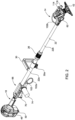
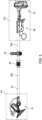
- FIGS. 1 and 2 illustrate a fluid dispensing scrubber 10 (e.g., a power scrubber 10) including a first end or scrubbing end 14 and a second end or base end 18.
- a shaft 22 connects the scrubbing end 14 to the base end 18.
- the shaft 22 may be a telescoping shaft including one or more telescoping portions (e.g., a first portion 22a and a second portion 22b that slide/telescope relative to each other), and a coupler 26 connecting the first portion 22a and the second portion 22b.
- a handle 30 surrounds the first portion 22a and is secured by a fastener 30a to the first portion 22a at a position between the base end 18 and the coupler 26.
- a scrubber head 34 is positioned adjacent the scrubbing end 14.
- the scrubber head 34 supports a motor 38.
- the motor 38 is operably coupled to a brush 42 and is in electrical communication with a battery pack 46.
- the brush 42 is adjacent the scrubbing end 14 and is operable to scrub a surface upon operation of the motor 38.
- the battery pack 46 engages a battery receptacle 50 adjacent the base end 18.
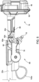
- One or more wires 54 ( FIGS. 7-9 ) pass through the telescopic shaft 22 to provide electrical communication between the battery pack 46 and the motor 38.
- a button 58 is provided on the exterior of the base end 18 to permit a user to control flow of power from the battery pack 46 to the motor 38 and to adjust operation of the motor 38.
- the scrubber head 34 is supported for pivoting movement by a pivot joint 62.
- the pivot joint 62 is positioned proximate the scrubbing end 14, at an end of the second portion 22b opposite the coupler 26.
- the telescopic shaft 22 extends along a longitudinal axis LA.
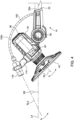
- a reference line RL1 extends through the scrubber head 34 and is substantially parallel to an axis of rotation of the brush 42.
- the reference line RL1 in the illustrated embodiment is oriented at an angle O1 relative to the longitudinal axis LA.
- the pivot joint 62 permits pivoting movement of the scrubber head 34, changing the orientation of the reference line RL1 relative to the longitudinal axis LA.
- the pivot joint 62 is lockable in a desired position to releasably secure the angle O1.
- the pivot joint 62 may be operable to permit the scrubber head 34 to be oriented parallel to the telescopic shaft 22.
- the reference line RL1 of the scrubber head 34 may extend parallel to the longitudinal axis LA.
- the fluid dispensing scrubber 10 further includes a mode selector assembly 66 operable to change an operating mode of the fluid dispensing feature of the scrubber 10.
- the scrubber 10 includes a fluid inlet nozzle 70 receiving fluid from an inlet fluid source.
- the fluid inlet nozzle 70 receives water.
- the fluid dispensing scrubber 10 also includes an on-board reservoir 74 ( FIG. 2 ) for holding a cleaning agent (e.g., soap or a detergent).
- the reservoir 74 is transparent such that a user may observe the fill level of the reservoir 74 without detachment of the reservoir 74 from the scrubber 10.
- a cover plate 78 is provided to shield internal components of the mode selector assembly 66 from the environment.
- An actuator 82 is provided on the exterior of the mode selector assembly 66 to permit a user to adjust the mode selector assembly 66 between operation modes, as discussed below.
- the actuator 82 is connected to a first end 86a of a bar linkage 86. Movement of the actuator 82 causes movement of the bar linkage 86.
- the second end 86b of the bar linkage 86 is connected to a valve plate 90.
- the valve plate 90 has a center portion 90a and a peripheral portion 90b spaced apart radially from the center portion 90a.
- the second end 86b of the bar linkage 86 is connected to the peripheral portion 90b.
- the actuator 82 is rotated, the bar linkage 86 causes rotation of the valve plate 90 and the center portion 90a.
- the center portion 90a of the valve plate 90 is secured to a valve 94 for co-rotation therewith.
- FIG. 7 illustrates the mode selector assembly 66 with the valve plate 90 hidden.
- a chamber 98 is provided between the fluid inlet nozzle 70 and a tube 102.
- the chamber 98 is also provided adjacent the reservoir 74 ( FIG. 2 ).
- the chamber 98 includes soap holes 106 which are aligned with the passageway 104.
- the soap holes 106 are configured to align with valve holes 110 when the actuator 82 is in a soap position 82a. As the actuator 82 moves the valve 94 out of the soap position 82a, the soap holes 106 become misaligned with the valve holes 110, and soap from the reservoir 74 is restricted from entry into the passageway 104.
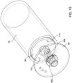
- the valve holes 110 are best illustrated in FIGS. 9 and 10 .
- the tube 102 has a base end portion 102a that is exterior to the valve housing and passes into the telescopic shaft 22. The tube 102 passes to the scrubbing end 14.
- the mode selector assembly 66 is configured to allow a combination of soap (or any cleaning agent) from the reservoir 74 and water (or any inlet fluid) from the fluid inlet nozzle 70 to pass to the tube 102.
- the fluid dispensing scrubber 10 dispenses a mixture of soap and water.
- the mode selector assembly 66 is configured to restrict soap from the reservoir 74 from entry to the tube 102 but permit water from the fluid inlet nozzle 70 to enter the tube 102. In the rinsing mode, water flushes residual soap from within the scrubber 10.
- the motor 38 receives power from the battery pack 46 to rotate the brush 42.
- the brush 42 may be operated in the scrub mode without dispensing soap from the reservoir 74 or water from the inlet nozzle 70.
- the motor 38 and the brush 42 may also be rotated in the soap mode and/or the rinse mode.
- the actuator 82 is moved to a rinse position 82b.
- the valve plate 90 is rotated such that the soap entry holes 106 and the valve holes 110 are misaligned.
- soap is restricted from entry to the passageway 104.
- the actuator 82 is moved to a scrub position 82c.
- the valve plate 90 is rotated such that the valve 94 restricts fluid from entering the tube 102 from the passageway 104.
- a scrubbing end portion 102b of the tube 102 opposes the base end portion 102a of the tube 102.
- the scrubbing end portion 102b is placed in fluid communication with a dispensing nozzle 118 configured to outlet fluid from the tube 102 adjacent the brush 42.
- the dispensing nozzle 118 is external to (i.e., spaced apart from) both the scrubber head 34 and the telescopic shaft 22.
- the scrubbing end portion 102b projects from the telescopic shaft 22 to the exterior of the scrubber 10.
- the dispensing nozzle 118 is secured to the scrubber head 34 by a yoke mechanism 114.
- the yoke mechanism 114 is pivotable relative to the scrubber head 34.
- a reference line RL2 extends through the dispensing nozzle 118.
- An angle ⁇ 2 is disposed between the longitudinal axis LA and the reference line RL2.
- the yoke mechanism 114 permits the dispensing nozzle 118 to be adjustable relative to the scrubber head 34. Additionally, the yoke mechanism 114 permits the dispensing nozzle 118 to be adjustable relative to the longitudinal axis LA. In some constructions, the yoke mechanism 114 is lockable in a desired position to secure the angle ⁇ 2 during operation of the scrubber 10.
- the yoke mechanism 114 is operable to permit the dispensing nozzle 118 to extend in a direction parallel with the scrubber head 34.
- the angle ⁇ 2 between the longitudinal axis LA and the reference line RL2 of the dispensing nozzle 118 may be made equal to the angle ⁇ 1 between the longitudinal axis LA and the reference line RL1 of the scrubber head 34.
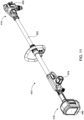
- FIGS. 11-15 illustrate a power scrubber 410 according to another embodiment.
- the scrubber 410 is similar in some aspects to the scrubber 10 described with respect to FIGS. 1-10 , and similar features are identified with similar reference numbers, plus 400. Some similarities and differences of the scrubber 410 are described herein.
- the scrubber 410 includes a first end or scrubbing end 414 and a second end or base end 418.
- a shaft 422 connects the scrubbing end 414 to the base end 418.
- a scrubber head 434 is positioned adjacent the scrubbing end 414 and supports a motor and brush (not shown).
- a battery pack 446 is positioned adjacent the base end 418.
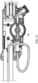
- an actuator 482 can be formed as a knob 482 that is aligned with the valve 494 ( FIG. 13 ) such that rotation of the knob 482 moves the valve 494 between a soap mode, a rinse mode, and a scrub mode.
- the scrubber head 434 is supported on a pivot joint 462, and a dispensing nozzle 518 is supported on the scrubber head 434 by a yoke 514.
- the yoke 514 is secured in a predetermined orientation relative to the scrubber head 434 to maintain the spray from the nozzle 518 at a desired orientation relative to the brush.
- the nozzle 518 is coupled to the yoke 514 by a quick coupling (e.g., a ball-in-socket coupling) that permits the nozzle to be disconnected easily without breaking and to be reinstalled. In some embodiments, this facilitates compact packaging and shipping.
- a quick coupling e.g., a ball-in-socket coupling
Landscapes
- Engineering & Computer Science (AREA)
- Mechanical Engineering (AREA)
- Brushes (AREA)
- Containers And Packaging Bodies Having A Special Means To Remove Contents (AREA)
- Cleaning In General (AREA)
- Nozzles (AREA)
Claims (11)
- Laveur à distribution de fluide comprenant :un arbre (22) comportant une première extrémité et une seconde extrémité ;une entrée de fluide (70) pour recevoir un fluide de rinçage provenant d'une source externe ;un réservoir (74) stockant un agent de nettoyage ;un ensemble vanne pour mélanger sélectivement le fluide de rinçage et l'agent de nettoyage ;une tête de lavage (34) supportée à côté de la première extrémité de l'arbre (22), la tête de lavage (34) comportant une brosse (42) et un moteur (38) exploitable pour faire tourner la brosse (42) ;un bloc-batterie (46) supporté à côté de la seconde extrémité, le bloc-batterie (46) étant exploitable pour fournir de le puissance au moteur (38) ; etune buse de distribution (118) pour distribuer sélectivement au moins l'un du fluide de rinçage et du fluide de nettoyage, la buse (118) étant supportée sur une surface extérieure de la tête de lavage (34).
- Laveur à distribution de fluide selon la revendication 1, dans lequel la buse de distribution de fluide (118) est supportée sur la surface extérieure de la tête de lavage (34) par un étrier (514), l'étrier (514) étant accouplé de manière pivotante à la tête de lavage (34) pour permettre le réglage de l'orientation de la buse de distribution par rapport à la tête de lavage (34).
- Laveur à distribution de fluide selon la revendication 1, dans lequel la buse de distribution de fluide (118) est bloquée contre tout mouvement par rapport à la tête de lavage (34).
- Laveur à distribution de fluide selon la revendication 1, dans lequel la buse de distribution de fluide (118) est accouplée à la tête de lavage (34) par un accouplement à rotule pour faciliter une connexion et une déconnexion rapides.
- Laveur à distribution de fluide selon la revendication 1, dans lequel l'ensemble vanne est mobile entre un mode de nettoyage, un mode de rinçage, et un mode de lavage, dans lequel, en mode de nettoyage, l'ensemble vanne permet à un mélange de l'agent de nettoyage et de l'agent de rinçage d'être distribué par la buse (118), dans lequel, en mode de rinçage, l'ensemble vanne permet uniquement au fluide de rinçage d'être distribué par la buse (118), dans lequel, en mode de lavage, l'ensemble vanne empêche le fluide de rinçage d'être distribué par la buse (118).
- Laveur à distribution de fluide selon la revendication 5, dans lequel le moteur (38) fait tourner la brosse (42) au moins en mode de lavage.
- Laveur à distribution de fluide selon la revendication 5, dans lequel le moteur (38) fait tourner la brosse (42) au moins en mode de nettoyage et en mode de lavage.
- Laveur à distribution de fluide selon la revendication 1, dans lequel l'ensemble vanne comporte un actionneur pour déplacer un élément de vanne, alors que l'ensemble vanne est dans un mode de nettoyage, l'élément de vanne fournit une communication de fluide entre au moins une ouverture et une voie de passage pour permettre l'entrée de l'agent de nettoyage du réservoir (74) dans la voie de passage pour se mélanger avec le fluide de rinçage.
- Laveur à distribution de fluide selon la revendication 1 :dans lequel l'arbre (22) comporte une première partie (22a) et une seconde partie (22b) accouplée de manière coulissante à la première partie (22a) ;le laveur à distribution de fluide comprenant en outre :une partie de préhension (30) accouplée à l'arbre (22) ; etune articulation pivotante (62) positionnée à côté de la première extrémité de l'arbre (22) ;dans lequel la tête de lavage (34) est accouplée à l'articulation pivotante (62), la tête de lavage (34) pouvant pivoter par rapport à l'arbre (22), la tête de lavage (34) comprenant en outre un mandrin exploitable pour être mis en rotation par le moteur (38), le mandrin étant accouplé à la brosse (42) et transmettant un couple du moteur (38) à la brosse (42).
- Laveur à distribution de fluide selon la revendication 9, dans lequel la buse de distribution de fluide (118) est supportée sur la surface extérieure de la tête de lavage (34) par un étrier (114), l'étrier (114) étant accouplé de manière pivotante à la tête de lavage (34) pour permettre le réglage de l'orientation de la buse de distribution par rapport à la tête de lavage (34).
- Laveur à distribution de fluide selon la revendication 10, dans lequel l'ensemble vanne est mobile entre un mode de nettoyage, un mode de rinçage, et un mode de lavage, dans lequel, en mode de nettoyage, l'ensemble vanne permet à un mélange de l'agent de nettoyage et de l'agent de rinçage d'être distribué par la buse (118), dans lequel, en mode de rinçage, l'ensemble vanne permet uniquement au fluide de rinçage d'être distribué par la buse (118), dans lequel, en mode de lavage, l'ensemble vanne empêche le fluide de rinçage d'être distribué par la buse (118).
Applications Claiming Priority (1)
| Application Number | Priority Date | Filing Date | Title |
|---|---|---|---|
| US202163190559P | 2021-05-19 | 2021-05-19 |
Publications (4)
| Publication Number | Publication Date |
|---|---|
| EP4101361A2 EP4101361A2 (fr) | 2022-12-14 |
| EP4101361A3 EP4101361A3 (fr) | 2023-02-22 |
| EP4101361B1 true EP4101361B1 (fr) | 2024-10-23 |
| EP4101361C0 EP4101361C0 (fr) | 2024-10-23 |
Family
ID=81748512
Family Applications (1)
| Application Number | Title | Priority Date | Filing Date |
|---|---|---|---|
| EP22173963.4A Active EP4101361B1 (fr) | 2021-05-19 | 2022-05-18 | Épurateur de distribution de fluide |
Country Status (4)
| Country | Link |
|---|---|
| US (1) | US12274353B2 (fr) |
| EP (1) | EP4101361B1 (fr) |
| CN (1) | CN218165153U (fr) |
| CA (1) | CA3158876A1 (fr) |
Families Citing this family (2)
| Publication number | Priority date | Publication date | Assignee | Title |
|---|---|---|---|---|
| HK1256429A2 (zh) * | 2018-08-16 | 2019-09-20 | Tti (Macao Commercial Offshore) Limited | 具有喷嘴和针作为组件的液体分配装置 |
| USD1033911S1 (en) * | 2023-06-19 | 2024-07-09 | Jiezhen Zhou | Cleaning brush |
Family Cites Families (57)
| Publication number | Priority date | Publication date | Assignee | Title |
|---|---|---|---|---|
| US1994085A (en) | 1933-07-27 | 1935-03-12 | Albert C Jackson | Fountain brush or mop |
| US2801431A (en) * | 1955-04-08 | 1957-08-06 | Truman D Eastis | Power driven brush having a swingable nozzle |
| US2986764A (en) | 1958-08-08 | 1961-06-06 | Hoover Co | Suction cleaner |
| US3024487A (en) | 1960-04-25 | 1962-03-13 | Reginald H Jones | Multipurpose scrubber |
| US3101505A (en) | 1961-07-18 | 1963-08-27 | Electrolux Corp | Surface treating machine |
| US3731334A (en) | 1971-06-11 | 1973-05-08 | M Carbonell | Bathtub scrubber |
| US4720883A (en) | 1986-08-21 | 1988-01-26 | Clyde Industries Limited | Interchangeable rotary scrub brush nozzle with swivel |
| CN2131448Y (zh) | 1992-05-08 | 1993-05-05 | 南京塑料五厂 | 多功能旋转式洗刷器 |
| US5356076A (en) * | 1993-03-29 | 1994-10-18 | Bishop Robert A | Shower soap dispenser for liquid soaps |
| US5649334A (en) | 1996-03-07 | 1997-07-22 | Henriquez; Jorge De Jesus Matias | Water and soap dispensing scrubber apparatus |
| CN2278425Y (zh) | 1996-08-27 | 1998-04-15 | 王均 | 多用途刷洗同步器 |
| CN2326175Y (zh) | 1998-03-24 | 1999-06-30 | 李英一 | 多用途喷淋洗刷器 |
| AT406633B (de) | 1998-04-14 | 2000-07-25 | Rotowash Reinigungsmasch Gmbh | Bodenreinigungsmaschine |
| EP1343409A2 (fr) | 2000-12-21 | 2003-09-17 | The Procter & Gamble Company | Dispositif portatif motorise de nettoyage et de distribution, et procede d'utilisation |
| WO2002049496A1 (fr) | 2000-12-21 | 2002-06-27 | The Procter & Gamble Company | Nettoyeur à moteur se tenant à la main, surface nettoyante jetable, et procédé d'utilisation correspondant |
| US20050278880A1 (en) | 2001-03-14 | 2005-12-22 | Lucio Pieroni | Motorized hand-held scrubbing device, a disposable scrubbing surface, and a method of use therefor |
| US6748619B2 (en) * | 2002-03-22 | 2004-06-15 | Trung Thieu Quach | Hand held, electric cleaning device |
| CA2515848A1 (fr) | 2003-02-13 | 2004-09-02 | Black & Decker Inc. | Outil a recurer a tenue manuelle |
| DE20302630U1 (de) | 2003-02-18 | 2003-04-30 | Hsu, Bill, Shinjuang, Taipeh | Dampfschrubbmaschine |
| US20040237228A1 (en) | 2003-05-29 | 2004-12-02 | Wade King | Power scrubber |
| US7040830B2 (en) | 2003-09-26 | 2006-05-09 | Helen Of Troy Limited | Soap dispensing apparatus |
| EP1529478B1 (fr) | 2003-11-07 | 2007-04-25 | BLACK & DECKER INC. | Brosseuse de sols électrique |
| US7481594B2 (en) | 2004-03-22 | 2009-01-27 | Mb Manufacturing | Weighted scrub brush |
| US20070020030A1 (en) | 2005-03-30 | 2007-01-25 | Goulet Matthew G | Liquid dispensing devices including an attached cleaning element |
| US20060218752A1 (en) | 2005-03-30 | 2006-10-05 | Potempa Michael M | Collet locks and extension pole assemblies comprising same |
| US7008130B1 (en) | 2005-06-17 | 2006-03-07 | Hill Samuel M | Window washing tool |
| EP1937106A1 (fr) | 2005-10-20 | 2008-07-02 | Larry C. Wilkins | Brosseuse portative a cartouche de distribution de liquide |
| US7703165B2 (en) | 2005-10-20 | 2010-04-27 | Wilkins Larry C | Portable scrubbing apparatus |
| US7979940B1 (en) | 2006-05-11 | 2011-07-19 | Wilkins Larry C | Fluid-powered liquid-dispenser apparatus |
| EP2359731B1 (fr) | 2006-02-13 | 2016-09-07 | Black & Decker Inc. | Balai-éponge à moteur doté d'une brosse de récurage escamotable |
| US7913345B2 (en) | 2006-08-15 | 2011-03-29 | Umagination Labs, L.P. | Systems and methods of a power tool system with interchangeable functional attachments |
| US7743683B2 (en) | 2006-08-15 | 2010-06-29 | Umagination Labs, L.P. | Systems and methods of a power tool system with interchangeable functional attachments powered by a direct rotational drive |
| US20080173138A1 (en) | 2006-08-15 | 2008-07-24 | Dayton Douglas C | Systems and methods of a vacuum cup bulb changer power tool system with interchangeable functional attachments |
| US7926141B2 (en) | 2006-08-15 | 2011-04-19 | Umagination Labs, L.P. | Systems and methods of a gutter cleaning system |
| US20080060149A1 (en) * | 2006-09-11 | 2008-03-13 | Xingyu Wu | Combination automobile detailing machine |
| US7775736B2 (en) | 2007-02-15 | 2010-08-17 | James In Song | Portable conversion washing device |
| DE102007010303A1 (de) | 2007-02-22 | 2008-08-28 | Flex-Elektrowerkzeuge Gmbh | Handgehaltene Reinigungs-/Schleifmaschine |
| WO2008109638A1 (fr) | 2007-03-06 | 2008-09-12 | Wagner Spray Tech Corporation | Brosse de nettoyage avec eau par impulsion |
| CN201019220Y (zh) | 2007-04-07 | 2008-02-13 | 王文高 | 一种多功能电动清洁刷 |
| CN201042279Y (zh) | 2007-05-11 | 2008-04-02 | 齐大卫 | 一种可组合式的清洗器刷板构件及刷柄构件 |
| CN201064424Y (zh) | 2007-06-14 | 2008-05-28 | 李全义 | 电动地面擦洗机 |
| US20100067972A1 (en) | 2008-09-18 | 2010-03-18 | Ashworth Robert Scott | Grill cleaning utensil |
| CN102452379A (zh) | 2010-10-25 | 2012-05-16 | 王德生 | 一种多功能清洁器 |
| USD658384S1 (en) | 2011-11-07 | 2012-05-01 | Pender David D | Power brush |
| CN102697433B (zh) | 2012-04-01 | 2015-09-09 | 张良 | 一种电动清洗器及其清洗方法 |
| CN203153642U (zh) | 2013-04-11 | 2013-08-28 | 赵山 | 小型多功能清理机 |
| US9332831B2 (en) | 2013-04-22 | 2016-05-10 | David Pender | Cleaning apparatus |
| US9380859B2 (en) | 2013-04-22 | 2016-07-05 | David Pender | Cleaning apparatus |
| CN206462954U (zh) | 2016-08-28 | 2017-09-05 | 胡未东 | 具有加液功能的手持式电动清洁器 |
| DE102016217098A1 (de) | 2016-09-08 | 2018-03-08 | Robert Bosch Gmbh | Handgehaltenes Fugenreinigungsgerät |
| CN107125913A (zh) | 2017-06-26 | 2017-09-05 | 苏州迈晧电器有限公司 | 一种多功能电动旋转刷 |
| CN207734116U (zh) | 2017-07-07 | 2018-08-17 | 张丹峰 | 家用清洗器 |
| CN109199267B (zh) | 2018-09-29 | 2020-12-25 | 孙宇博 | 一种水洗清洁装置 |
| CN109567689A (zh) | 2018-12-29 | 2019-04-05 | 象山谢海家具有限公司 | 手持式地毯去污机 |
| DE202019102533U1 (de) | 2019-05-06 | 2019-05-14 | Einhell Germany Ag | Elektrisches Reinigungsgerät zum motorisch unterstützten Reinigen von Oberflächen |
| US11793383B2 (en) | 2019-07-03 | 2023-10-24 | Daniel L. Pampel | Awning cleaning tool |
| CN111528724B (zh) | 2020-06-12 | 2025-03-28 | 苏州市职业大学 | 一种便携式电动擦洗一体装置 |
-
2022
- 2022-05-12 CA CA3158876A patent/CA3158876A1/fr active Pending
- 2022-05-16 US US17/745,245 patent/US12274353B2/en active Active
- 2022-05-18 EP EP22173963.4A patent/EP4101361B1/fr active Active
- 2022-05-19 CN CN202221246359.3U patent/CN218165153U/zh active Active
Also Published As
| Publication number | Publication date |
|---|---|
| US12274353B2 (en) | 2025-04-15 |
| EP4101361A3 (fr) | 2023-02-22 |
| EP4101361A2 (fr) | 2022-12-14 |
| CA3158876A1 (fr) | 2022-11-19 |
| US20220369801A1 (en) | 2022-11-24 |
| CN218165153U (zh) | 2022-12-30 |
| EP4101361C0 (fr) | 2024-10-23 |
Similar Documents
| Publication | Publication Date | Title |
|---|---|---|
| EP4101361B1 (fr) | Épurateur de distribution de fluide | |
| US20080201877A1 (en) | Hand-held cleaning/polishing machine | |
| US7708485B2 (en) | Cleaning implement | |
| US20040237228A1 (en) | Power scrubber | |
| US8122554B2 (en) | Scrubbing device | |
| JP7606901B2 (ja) | 送風機及び噴霧器アタッチメント | |
| WO2019192482A1 (fr) | Brosse à entraînement hydraulique et machine de nettoyage l'utilisant | |
| US20130228355A1 (en) | Power tool | |
| US12370564B2 (en) | Outdoor surface cleaning apparatus with spray mechanism | |
| US7708484B2 (en) | Cleaning implement | |
| US20090045271A1 (en) | Handheld electric pressure washer | |
| EP1529478B1 (fr) | Brosseuse de sols électrique | |
| US20220409002A1 (en) | Floor cleaning machine | |
| CN114468867B (zh) | 清洁工具 | |
| US20080060149A1 (en) | Combination automobile detailing machine | |
| CN217601549U (zh) | 电动工具 | |
| JP2022161015A (ja) | 洗浄器具 | |
| CN118556981A (zh) | 便携式手持清洁工具 | |
| JP2018062022A (ja) | 手持ち式電動研磨装置 | |
| MXPA98003965A (en) | Hand vacuum with switching capacity between the suction path corresponding to the place to be clean |
Legal Events
| Date | Code | Title | Description |
|---|---|---|---|
| PUAI | Public reference made under article 153(3) epc to a published international application that has entered the european phase |
Free format text: ORIGINAL CODE: 0009012 |
|
| STAA | Information on the status of an ep patent application or granted ep patent |
Free format text: STATUS: THE APPLICATION HAS BEEN PUBLISHED |
|
| AK | Designated contracting states |
Kind code of ref document: A2 Designated state(s): AL AT BE BG CH CY CZ DE DK EE ES FI FR GB GR HR HU IE IS IT LI LT LU LV MC MK MT NL NO PL PT RO RS SE SI SK SM TR |
|
| PUAL | Search report despatched |
Free format text: ORIGINAL CODE: 0009013 |
|
| AK | Designated contracting states |
Kind code of ref document: A3 Designated state(s): AL AT BE BG CH CY CZ DE DK EE ES FI FR GB GR HR HU IE IS IT LI LT LU LV MC MK MT NL NO PL PT RO RS SE SI SK SM TR |
|
| RIC1 | Information provided on ipc code assigned before grant |
Ipc: A47L 11/283 20060101ALI20230117BHEP Ipc: A47L 11/26 20060101ALI20230117BHEP Ipc: A47L 11/16 20060101ALI20230117BHEP Ipc: A47L 11/14 20060101AFI20230117BHEP |
|
| STAA | Information on the status of an ep patent application or granted ep patent |
Free format text: STATUS: REQUEST FOR EXAMINATION WAS MADE |
|
| 17P | Request for examination filed |
Effective date: 20230822 |
|
| RBV | Designated contracting states (corrected) |
Designated state(s): AL AT BE BG CH CY CZ DE DK EE ES FI FR GB GR HR HU IE IS IT LI LT LU LV MC MK MT NL NO PL PT RO RS SE SI SK SM TR |
|
| GRAP | Despatch of communication of intention to grant a patent |
Free format text: ORIGINAL CODE: EPIDOSNIGR1 |
|
| STAA | Information on the status of an ep patent application or granted ep patent |
Free format text: STATUS: GRANT OF PATENT IS INTENDED |
|
| INTG | Intention to grant announced |
Effective date: 20240503 |
|
| GRAS | Grant fee paid |
Free format text: ORIGINAL CODE: EPIDOSNIGR3 |
|
| GRAA | (expected) grant |
Free format text: ORIGINAL CODE: 0009210 |
|
| STAA | Information on the status of an ep patent application or granted ep patent |
Free format text: STATUS: THE PATENT HAS BEEN GRANTED |
|
| AK | Designated contracting states |
Kind code of ref document: B1 Designated state(s): AL AT BE BG CH CY CZ DE DK EE ES FI FR GB GR HR HU IE IS IT LI LT LU LV MC MK MT NL NO PL PT RO RS SE SI SK SM TR |
|
| REG | Reference to a national code |
Ref country code: GB Ref legal event code: FG4D |
|
| REG | Reference to a national code |
Ref country code: CH Ref legal event code: EP |
|
| REG | Reference to a national code |
Ref country code: DE Ref legal event code: R096 Ref document number: 602022006985 Country of ref document: DE |
|
| REG | Reference to a national code |
Ref country code: IE Ref legal event code: FG4D |
|
| U01 | Request for unitary effect filed |
Effective date: 20241101 |
|
| U07 | Unitary effect registered |
Designated state(s): AT BE BG DE DK EE FI FR IT LT LU LV MT NL PT RO SE SI Effective date: 20241113 |
|
| PG25 | Lapsed in a contracting state [announced via postgrant information from national office to epo] |
Ref country code: HR Free format text: LAPSE BECAUSE OF FAILURE TO SUBMIT A TRANSLATION OF THE DESCRIPTION OR TO PAY THE FEE WITHIN THE PRESCRIBED TIME-LIMIT Effective date: 20241023 Ref country code: IS Free format text: LAPSE BECAUSE OF FAILURE TO SUBMIT A TRANSLATION OF THE DESCRIPTION OR TO PAY THE FEE WITHIN THE PRESCRIBED TIME-LIMIT Effective date: 20250223 |
|
| PG25 | Lapsed in a contracting state [announced via postgrant information from national office to epo] |
Ref country code: ES Free format text: LAPSE BECAUSE OF FAILURE TO SUBMIT A TRANSLATION OF THE DESCRIPTION OR TO PAY THE FEE WITHIN THE PRESCRIBED TIME-LIMIT Effective date: 20241023 |
|
| PG25 | Lapsed in a contracting state [announced via postgrant information from national office to epo] |
Ref country code: NO Free format text: LAPSE BECAUSE OF FAILURE TO SUBMIT A TRANSLATION OF THE DESCRIPTION OR TO PAY THE FEE WITHIN THE PRESCRIBED TIME-LIMIT Effective date: 20250123 |
|
| PG25 | Lapsed in a contracting state [announced via postgrant information from national office to epo] |
Ref country code: GR Free format text: LAPSE BECAUSE OF FAILURE TO SUBMIT A TRANSLATION OF THE DESCRIPTION OR TO PAY THE FEE WITHIN THE PRESCRIBED TIME-LIMIT Effective date: 20250124 |
|
| PG25 | Lapsed in a contracting state [announced via postgrant information from national office to epo] |
Ref country code: PL Free format text: LAPSE BECAUSE OF FAILURE TO SUBMIT A TRANSLATION OF THE DESCRIPTION OR TO PAY THE FEE WITHIN THE PRESCRIBED TIME-LIMIT Effective date: 20241023 |
|
| PG25 | Lapsed in a contracting state [announced via postgrant information from national office to epo] |
Ref country code: RS Free format text: LAPSE BECAUSE OF FAILURE TO SUBMIT A TRANSLATION OF THE DESCRIPTION OR TO PAY THE FEE WITHIN THE PRESCRIBED TIME-LIMIT Effective date: 20250123 |
|
| U20 | Renewal fee for the european patent with unitary effect paid |
Year of fee payment: 4 Effective date: 20250527 |
|
| PG25 | Lapsed in a contracting state [announced via postgrant information from national office to epo] |
Ref country code: SM Free format text: LAPSE BECAUSE OF FAILURE TO SUBMIT A TRANSLATION OF THE DESCRIPTION OR TO PAY THE FEE WITHIN THE PRESCRIBED TIME-LIMIT Effective date: 20241023 |
|
| PG25 | Lapsed in a contracting state [announced via postgrant information from national office to epo] |
Ref country code: SK Free format text: LAPSE BECAUSE OF FAILURE TO SUBMIT A TRANSLATION OF THE DESCRIPTION OR TO PAY THE FEE WITHIN THE PRESCRIBED TIME-LIMIT Effective date: 20241023 |
|
| PG25 | Lapsed in a contracting state [announced via postgrant information from national office to epo] |
Ref country code: CZ Free format text: LAPSE BECAUSE OF FAILURE TO SUBMIT A TRANSLATION OF THE DESCRIPTION OR TO PAY THE FEE WITHIN THE PRESCRIBED TIME-LIMIT Effective date: 20241023 |
|
| PLBE | No opposition filed within time limit |
Free format text: ORIGINAL CODE: 0009261 |
|
| STAA | Information on the status of an ep patent application or granted ep patent |
Free format text: STATUS: NO OPPOSITION FILED WITHIN TIME LIMIT |
|
| 26N | No opposition filed |
Effective date: 20250724 |
|
| REG | Reference to a national code |
Ref country code: CH Ref legal event code: H13 Free format text: ST27 STATUS EVENT CODE: U-0-0-H10-H13 (AS PROVIDED BY THE NATIONAL OFFICE) Effective date: 20251223 |
|
| PG25 | Lapsed in a contracting state [announced via postgrant information from national office to epo] |
Ref country code: CH Free format text: LAPSE BECAUSE OF NON-PAYMENT OF DUE FEES Effective date: 20250531 |
|
| PG25 | Lapsed in a contracting state [announced via postgrant information from national office to epo] |
Ref country code: MC Free format text: LAPSE BECAUSE OF FAILURE TO SUBMIT A TRANSLATION OF THE DESCRIPTION OR TO PAY THE FEE WITHIN THE PRESCRIBED TIME-LIMIT Effective date: 20241023 |
|
| PG25 | Lapsed in a contracting state [announced via postgrant information from national office to epo] |
Ref country code: IE Free format text: LAPSE BECAUSE OF NON-PAYMENT OF DUE FEES Effective date: 20250518 |