EP4101409A1 - Robot chirurgical - Google Patents
Robot chirurgical Download PDFInfo
- Publication number
- EP4101409A1 EP4101409A1 EP21753547.5A EP21753547A EP4101409A1 EP 4101409 A1 EP4101409 A1 EP 4101409A1 EP 21753547 A EP21753547 A EP 21753547A EP 4101409 A1 EP4101409 A1 EP 4101409A1
- Authority
- EP
- European Patent Office
- Prior art keywords
- distal end
- endoscope
- display
- treatment instrument
- surgical robot
- Prior art date
- Legal status (The legal status is an assumption and is not a legal conclusion. Google has not performed a legal analysis and makes no representation as to the accuracy of the status listed.)
- Granted
Links
Images


Classifications
-
- A—HUMAN NECESSITIES
- A61—MEDICAL OR VETERINARY SCIENCE; HYGIENE
- A61B—DIAGNOSIS; SURGERY; IDENTIFICATION
- A61B34/00—Computer-aided surgery; Manipulators or robots specially adapted for use in surgery
- A61B34/30—Surgical robots
-
- A—HUMAN NECESSITIES
- A61—MEDICAL OR VETERINARY SCIENCE; HYGIENE
- A61B—DIAGNOSIS; SURGERY; IDENTIFICATION
- A61B1/00—Instruments for performing medical examinations of the interior of cavities or tubes of the body by visual or photographical inspection, e.g. endoscopes; Illuminating arrangements therefor
- A61B1/00002—Operational features of endoscopes
- A61B1/00004—Operational features of endoscopes characterised by electronic signal processing
- A61B1/00006—Operational features of endoscopes characterised by electronic signal processing of control signals
-
- A—HUMAN NECESSITIES
- A61—MEDICAL OR VETERINARY SCIENCE; HYGIENE
- A61B—DIAGNOSIS; SURGERY; IDENTIFICATION
- A61B1/00—Instruments for performing medical examinations of the interior of cavities or tubes of the body by visual or photographical inspection, e.g. endoscopes; Illuminating arrangements therefor
- A61B1/00002—Operational features of endoscopes
- A61B1/00043—Operational features of endoscopes provided with output arrangements
- A61B1/00045—Display arrangement
- A61B1/0005—Display arrangement combining images e.g. side-by-side, superimposed or tiled
-
- A—HUMAN NECESSITIES
- A61—MEDICAL OR VETERINARY SCIENCE; HYGIENE
- A61B—DIAGNOSIS; SURGERY; IDENTIFICATION
- A61B1/00—Instruments for performing medical examinations of the interior of cavities or tubes of the body by visual or photographical inspection, e.g. endoscopes; Illuminating arrangements therefor
- A61B1/00147—Holding or positioning arrangements
- A61B1/00149—Holding or positioning arrangements using articulated arms
-
- A—HUMAN NECESSITIES
- A61—MEDICAL OR VETERINARY SCIENCE; HYGIENE
- A61B—DIAGNOSIS; SURGERY; IDENTIFICATION
- A61B34/00—Computer-aided surgery; Manipulators or robots specially adapted for use in surgery
- A61B34/30—Surgical robots
- A61B34/37—Leader-follower robots
-
- A—HUMAN NECESSITIES
- A61—MEDICAL OR VETERINARY SCIENCE; HYGIENE
- A61B—DIAGNOSIS; SURGERY; IDENTIFICATION
- A61B34/00—Computer-aided surgery; Manipulators or robots specially adapted for use in surgery
- A61B34/30—Surgical robots
- A61B2034/301—Surgical robots for introducing or steering flexible instruments inserted into the body, e.g. catheters or endoscopes
-
- A—HUMAN NECESSITIES
- A61—MEDICAL OR VETERINARY SCIENCE; HYGIENE
- A61B—DIAGNOSIS; SURGERY; IDENTIFICATION
- A61B34/00—Computer-aided surgery; Manipulators or robots specially adapted for use in surgery
- A61B34/30—Surgical robots
- A61B2034/302—Surgical robots specifically adapted for manipulations within body cavities, e.g. within abdominal or thoracic cavities
-
- A—HUMAN NECESSITIES
- A61—MEDICAL OR VETERINARY SCIENCE; HYGIENE
- A61B—DIAGNOSIS; SURGERY; IDENTIFICATION
- A61B90/00—Instruments, implements or accessories specially adapted for surgery or diagnosis and not covered by any of the groups A61B1/00 - A61B50/00, e.g. for luxation treatment or for protecting wound edges
- A61B90/36—Image-producing devices or illumination devices not otherwise provided for
- A61B90/37—Surgical systems with images on a monitor during operation
- A61B2090/371—Surgical systems with images on a monitor during operation with simultaneous use of two cameras
-
- A—HUMAN NECESSITIES
- A61—MEDICAL OR VETERINARY SCIENCE; HYGIENE
- A61B—DIAGNOSIS; SURGERY; IDENTIFICATION
- A61B90/00—Instruments, implements or accessories specially adapted for surgery or diagnosis and not covered by any of the groups A61B1/00 - A61B50/00, e.g. for luxation treatment or for protecting wound edges
- A61B90/36—Image-producing devices or illumination devices not otherwise provided for
- A61B90/361—Image-producing devices, e.g. surgical cameras
Definitions
- the present disclosure relates to a surgical robot for use in endoscopic surgery.
- Endoscopic surgery such as laparoscopic surgery is performed by the following procedure.
- Trocar is also called trocar.
- an endoscope inserts an endoscope, forceps, an electric scalpel or the like to each trocar, and performs surgery while looking at an image captured by the endoscope.
- Forceps are an instrument for gripping and pulling an internal organ or the like, and can be remotely controlled.
- an instrument such as forceps and an electric scalpel, for use in treatments performed during surgery is referred to as a treatment instrument.
- Patent Document 1 Japanese Patent No. 4999012
- the operator such as a doctor performs surgery while looking at the image captured by the endoscope.
- the operator will lose sight of the treatment instrument and the surgery will be delayed.
- the present disclosure discloses an example of a surgical robot that allows the operator to easily deal even with the case where the distal end position of the treatment instrument deviates from the imaging region.
- a surgical robot for use in endoscopic surgery comprises at least one of the following components, for example.
- the components are: a position information calculator that calculates information relating to a distal end position of a treatment instrument used in endoscopic surgery, and information relating to a distal end position of an endoscope; a first display section that displays a relative positional relationship between the distal end of the treatment instrument and the distal end of the endoscope by using a calculation result obtained from the position information calculator; and a second display section that displays an image captured by the endoscope.
- the surgical robot may be configured as follows, for example.
- a circular protractor based on the distal end position of the endoscope is displayed on the first display section, together with the aforementioned positional relationship.
- the operator can easily grasp the distal end position of the treatment instrument.
- a figure representing the distal end of the endoscope is displayed in the center of the display screen, and further, in accordance with changes in the positional relationship, a display mode of a figure representing the treatment instrument or a display position of the figure changes.
- the operator can easily grasp the distal end position of the treatment instrument.
- an up-down direction of the display screen coincides with a vertical direction.
- the operator can easily grasp the distal end position of the treatment instrument.
- a display angle of the camera icon relative to the display screen changes in accordance with an angle of rotation of the endoscope.
- the member or portion described with a reference numeral affixed thereto there is at least one in number unless specified as “one” or the like. In other words, the member or portion may be two or more in number unless specified as “one”.
- the surgical robot shown in the present disclosure comprises at least components such as members or portions described with reference numerals affixed thereto, and structural portions shown in the drawings.
- the present embodiment is an example of a surgical robot for use in endoscopic surgery.
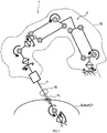
- a surgical robot 1 comprises a control device 5, an arm drive device 9, a first display section 19 and a second display section 25, in addition to a robot arm 3 (see FIG. 1 ).
- the robot arm 3 is an example of an arm device holding a treatment instrument 7, as shown in FIG. 1 .
- the robot arm 3 is configured by a link mechanism that has two or more joints and that can change a position of pivot.
- the pivot is a position which is an immovable point when the robot arm 3 operates, regardless of a state of the robot arm 3.
- the treatment instrument 7 is an instrument, such as forceps and an electric scalpel, used in treatments performed during surgery.
- the treatment instrument 7 shown in FIG. 1 is forceps. At a distal end of the forceps, a hand part for gripping and pulling an internal organ or the like is provided.
- the robot arm 3 is covered by a tubular drape 20.
- the drape 20 is a flexible, non-woven fabric covering member.
- An endoscope 27 (see FIG. 2 ) is gripped by a second robot arm.
- the treatment instrument 7 and the endoscope 27 are collectively called surgical instrument.
- the surgical instrument is an instrument used for endoscopic surgery, such as an endoscope, forceps and an electric scalpel.
- the arm drive device 9 is an example of a drive device that drives the robot arm 3.
- the arm drive device 9 according to the present embodiment comprises two or more electric motors, an air pressure cylinder, and a pressure generator.
- Each electric motor drives the corresponding joint.
- the air pressure cylinder applies tension to a wire that drives the treatment instrument 7 (for example, hand part of the forceps).
- the pressure generator supplies a compressed air to the air pressure cylinder.
- the second robot arm is driven by a second arm drive device.
- the second arm drive device has the same configuration as that of the arm drive device 9. Operation of the second arm drive device is controlled in the same manner as that of the arm drive device 9.
- the control device 5 comprises at least an immovable point setter 11, a drive controller 13, a first display processor 21A, a second display processor 21B, a third display processor 29 and an image processor 25A, as shown in FIG. 2 .
- the immovable point setter 11 recognizes a position of a site where a trocar 15 (see FIG. 1 ) is inserted during surgery (hereinafter, also referred to as an incision position), and stores the recognized position as a pivot P 1 .
- immovable point setting a series of operations from recognition of the incision position to storage of the position, etc. by the immovable point setter 11 is referred to as immovable point setting.
- a state in which the immovable point setting can be performed is referred to as an immovable point setting mode.
- the trocar 15 is a cylindrical member to be inserted into a hole incised in a subject.
- a surgical instrument like the treatment instrument 7, such as forceps, and the endoscope 27 is inserted into a body of the subject through the trocar 15 inserted to an incision site.
- the drive controller 13 uses the position of the pivot P 1 to control operation of the arm drive device 9. Specifically, the drive controller 13 receives a command signal outputted from a master-side input operation device, and activates the arm drive device 9 according to the command signal.
- the drive controller 13 activates the arm drive device 9 so that a portion of the treatment instrument 7 corresponding to the pivot P 1 is immovable.
- the mater-side input operation device is an example of an input device which is directly operated by an operator such as a doctor.
- Operation of the second arm drive device is controlled by a second drive controller.
- the second drive controller activates the second robot arm with the incision site where the endoscope 27 is to be inserted as the pivot P 1 .
- the pivot is an immovable point set by a second immovable point setter.
- the second immovable point setter is identical to the immovable point setter 11, and thus a detailed description of the second immovable point setter is omitted herein.
- the surgical robot uses the input operation device for the robot arm 3 (in other words, arm drive device 9) to transmit the command signal to the second arm drive device.
- the surgical robot is provided with a selector switch.
- the selector switch can switch an output destination of the aforementioned command signal between the arm drive device 9 and the second arm drive device.
- the operator operates the selector switch to switch between activation of the robot arm 3 and activation of the second robot arm.
- the immovable point setter 11 can execute a position recognition function and a memory function.
- the immovable point setter 11 uses the position recognition function and the memory function to store the position of the pivot P 1 as an immovable point.
- the position recognition function is a function to recognize a distal end position of the treatment instrument 7 held by the robot arm 3.
- the memory function stores the distal end position recognized by the position recognition function as the pivot P 1 .
- the pivot P 1 stored by the memory function may be, for example, a position recognized by the position recognition function.
- the position recognized by the position recognition function is not limited to the distal end position of the treatment instrument 7.
- the position recognized by the position recognition function may be, for example, the incision position which is the position of a site where the trocar 15 is to be inserted during surgery.
- the position recognition function recognizes the distal end position of the treatment instrument 7 by obtaining or calculating a coordinate or the like which indicates the distal end position of the treatment instrument 7 from an attitude of the robot arm 3.
- the memory function stores the coordinate as the pivot P 1 .
- a surgical instrument equivalent may be used instead of the treatment instrument 7.
- the surgical instrument equivalent is a member having a shape similar to that of the treatment instrument 7. Specifically, for example, a rod-shaped or pipe-shaped member corresponds to the surgical instrument equivalent.
- the endoscope 27 corresponds to the surgical instrument equivalent.
- the position recognition function and memory function according to the present embodiment are implemented by a software, programs that make up the software, and a microcomputer.
- the microcomputer at least comprises a CPU, a ROM and a RAM to run the software.
- the software is stored in a non-volatile storage section in advance.
- the surgical robot 1 has a setting button 17A, a free displacement enabling button 17B and the like, as shown in FIG. 2 .
- the setting button 17A and the free displacement enabling button 17B are provided in at least one of the robot arm 3 and the control device 5.
- the robot arm 3 corresponds to an example of a slave device
- the control device 5 corresponds to an example of a master-side device.
- the setting button 17A is an example of a setting operating section operated by a user.
- the user is the one who performs an immovable point setting work. Specifically, the user is an operator or those who assist surgery.
- an immovable point setting mode starts or ends.
- the immovable point setting mode is started. If the setting button 17A is operated in the immovable point setting mode, the immovable point setting mode ends.
- the immovable point setting mode is started.
- the position recognition function is enabled.
- the setting button 17A When the setting button 17A is depressed less than the specified time (for example, two seconds), the position recognition function is executed and then the memory function is executed. Thereafter, the pivot P 1 is stored as the immovable point, and the immovable point setting mode ends.
- the specified time for example, two seconds
- the free displacement enabling button 17B is an example of the operating section operated by the user.
- the arm drive device 9 is brought into a free displacement mode.
- the free displacement mode is a mode in which the robot arm 3 is freely displaceable in accordance with an external force acting on the robot arm 3.
- the user can freely displace the robot arm 3 by pushing and pulling the robot arm 3.
- the user can align the distal end of the treatment instrument 7 with the incision position by pushing and pulling the robot arm 3 without operating the master-side input operation device.
- the free displacement mode ends "if the free displacement enabling button 17B is operated in the free displacement mode", or "when the immovable point setting mode ends". In a state in which the free displacement mode is not started, the robot arm 3 is not displaced even if an external force acts on the robot arm 3.
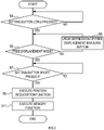
- FIG. 3 shows an example control of the control device 5 executed in the immovable point setting mode.
- the control device 5 determines whether the setting button 17A is depressed for more than a specified time (for example, three seconds) (S1).
- S1 a specified time
- “(S1)" and the like indicate control step numbers illustrated in FIG. 3 .
- the control device 5 when determining that the setting button 17A is depressed for more than the specified time (S1: YES), determines whether the arm drive device 9 is in the free displacement mode (S3).
- the control device 5 when determining that the arm drive device 9 is not in the free displacement mode (S3: NO), urges the user to operate the free displacement enabling button 17B by sound (for example, buzzer) or by a notification device such as a warning light (S5).
- the control device 5 determines whether the setting button 17A is depressed for less than the specified time (for example, two seconds) (S7).
- the control device 5 when determining that the setting button 17A is depressed for less than the specified time (S7: YES), executes the position recognition function (S9), and then executes the memory function (S11).
- the control device 5 after storing the pivot P 1 as the immovable point, ends the immovable point setting mode and the free displacement mode, and notifies the user that the pivot P 1 is stored as the immovable point.
- the first display section 19 and the second display section 25 shown in FIG. 2 are monitors that transmit information such as text information and image information to the user.
- information relating to the surgical robot 1 hereinafter, referred to as state information), etc. are displayed.
- state information information relating to the surgical robot 1
- an image captured by the endoscope 27 is displayed.
- the endoscope 27 is configured by a camera such as a stereo camera that can image an object three-dimensionally.
- the image processor 25A is a processor for displaying a three-dimensional image on the second display section 25.
- the first display processor 21A and the second display processor 21B display information on the first display section 19.
- the first display processor 21A displays a relative positional relationship between the incision position, that is, the pivot P 1 and the distal end position of the treatment instrument 7 on the first display section 19.
- the first display processor 21A uses image information such as figures (for example, icons) to display the relative positional relationship on the display section 19.
- Each icon has a figure which represents the pivot P 1 or the distal end position of the treatment instrument 7.
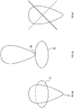
- FIG. 4A shows a case where the distal end position St of the treatment instrument 7 is located inside a body relative to the pivot P 1 .
- FIG. 4B shows a case where the distal end position St of the treatment instrument 7 is located outside the body relative to the pivot P 1 .
- FIG. 4C shows a state in which the immovable point setting is not yet performed.
- the second display processor 21B displays a detection result of the drape detector 23 (see FIG. 2 ) on the first display section 19.
- the drape detector 23 detects whether the drape 20 is attached to the robot arm 3.
- the drape detector 23 is provided in the robot arm 3.
- the second display processor 21B displays that information (for example, see FIG. 5A ) on the display section 19. If the drape 20 is not attached, the second display processor 21B displays that information (for example, see FIG. 5B ) on the display section 19.
- the third display processor 29 displays a relative positional relationship between the distal end position of the treatment instrument 7 and the distal end position of the endoscope 27 on the first display section 19. In other words, the third display processor 29 can perform at least three functions.
- the first function is a function to obtain information relating to the distal end position of the treatment instrument 7.
- the second function is a position information calculation function to calculate information relating to the distal end position of the endoscope 27.
- the third function is a function to display the information relating to the distal end position of the treatment instrument 7 and the information relating to the distal end position of the endoscope 27 on the first display section 19.
- the third display processor 29 uses the aforementioned position recognition function to achieve the first function and the second function.
- the third display processor 29 uses a calculation result by the position information calculation function to display the relative positional relationship between the distal end of the treatment instrument 7 and the distal end of the endoscope 27. Specifically, as shown in FIG. 6 , a figure (for example, icon) 29B representing the distal end of the treatment instrument 7 and a figure (for example, icon) 29A representing the distal end of the endoscope 27 are at least displayed on the first display section 19.
- a circular protractor 29C based on the position of the distal end of the endoscope 27 is displayed.
- the circular protractor 29C is displayed in a state in which a center of the circular protractor 29C coincides with a center of the display screen of the first display section 19.
- the center of the display screen of the first display section 19 means the center of the physical display screen when only the second state information is displayed on the first display section 19, and means a center of a display area of the second state information when other information (for example, first state information), in addition to the second state information, is also displayed on the first display section 19.
- the center of the display area of the second state information coincides with the center of the physical display screen. Therefore, even if two or more types of state information are displayed, the center of the circular protractor 29C coincides with the center of the physical display screen.
- the icon (hereinafter, also referred to as a camera icon) 29A representing the distal end of the endoscope 27 is displayed in the center of the display screen.
- a display mode of the icon 29B representing the treatment instrument 7 or a display position of the icon 29B changes in accordance with changes in the relative positional relationship between the distal end position of the treatment instrument 7 and the distal end position of the endoscope 27.
- the display mode of the icon 29B means, for example, specific designs of the icon 29B, that is, the shape, pattern, and color of the icon 29B or combinations thereof, or how to display those specific designs (for example, blinking display and always-on display ), etc.
- An up-down direction of the display screen or the display area coincides with a vertical direction.
- the display angle of the camera icon 29A relative to the display screen changes in accordance with an angle of rotation of the endoscope 27.
- the camera icon 29A also rotates in conjunction with the rotation of the endoscope 27.
- a center position of the camera icon 29A always coincides with the center of the display screen (in other words, center of the circular protractor 29C) regardless of the physical position of the endoscope 27.
- the relative positional relationship between the distal end of the treatment instrument 7 and the distal end of the endoscope 27 is displayed on the first display section 19.
- the operator can easily deal even with the case where the distal end position of the treatment instrument 7 deviates from the imaging region.
- the monitor to display the state information and the monitor to display the image captured by the endoscope 27 is separately provided. This facilitates surgery by the operator.
- the monitor to display the state information corresponds to an example of the configuration as the first display section 19
- the monitor to display the image captured by the endoscope 27 corresponds to an example of the configuration as the second display section 25.
- the state information is also displayed on the second display section 25, it becomes difficult for the operator to perform surgery since the display of the state information partially hides the captured image.
- the circular protractor 29C based on the position of the distal end of the endoscope 27 is displayed on the first display section 19. This allows the operator to easily grasp the distal end position of the treatment instrument 7.
- the icon 29A representing the distal end of the endoscope 27 is displayed in the center of the display screen, and, in accordance with changes in the positional relationship, the display mode of the icon 29B representing the treatment instrument 7 or the display position of the icon 29B changes. This allows the operator to easily grasp the distal end position of the treatment instrument 7.
- the up-down direction of the display screen coincides with the vertical direction. This allows the operator to easily grasp the distal end position of the treatment instrument 7.
- the relative positional relationship between the site where the trocar 15 is to be inserted during surgery and the distal end position of the treatment instrument 7 is displayed on the first display section 19. This allows the operator to confirm "whether the treatment instrument 7 is moving so that the portion of the treatment instrument 7 corresponding to the incision site is immovable".
- the first display processor 21A uses the position stored by the immovable point setter 11 as the site where the trocar 15 is to be inserted. This allows the operator to easily and reliably recognize whether the immovable point setter 11 stores the incision position as the immovable point.
- the detection result of the drape detector 23 is displayed on the first display section 19. This allows the operator to easily and reliably recognize whether surgery by the surgical robot 1 is ready to be performed.
- the surgical robot 1 recognizes the position of the site where the trocar 15 is to be inserted during surgery, that is, the incision position, and stores the recognized position as the pivot P 1 . Thus, in the surgical robot 1, alignment work between the position of the pivot P 1 and the incision site can be easily performed.
- the arm drive device 9 can execute the free displacement mode.
- the user can execute the position recognition function and the memory function after aligning the distal end of the treatment instrument 7 with the incision site. Accordingly, alignment work between the position of the pivot P 1 and the incision site can be easily performed.
- the robot arm 3 for holding the treatment instrument 7 and the second robot arm for holding the endoscope 27 are provided.
- the present disclosure is not limited to the configuration provided with the second robot arm.
- the present disclosure may be configured so that there is no second robot arm and the endoscope 27 is held by an assistant or that there are two or more robot arms 3 which hold two or more treatment instruments 7.
- the circular protractor 29C based on the position of the distal end of the endoscope 27 is displayed on the first display section 19.
- the present disclosure is not limited to the configuration in which the circular protractor 29C is displayed on the first display section 19.
- the present disclosure may be configured so that the circular protractor 29C is not displayed.
- the up-down direction of the display screen coincides with the vertical direction, and, in accordance with changes in the positional relationship, the display mode of the icon 29B representing the treatment instrument 7 or the display position of the icon 29B changes.
- the present disclosure is not limited to the configuration in which the up-down direction of the display screen coincides with the vertical direction, and, in accordance with changes in the positional relationship, the display mode of the icon 29B representing the treatment instrument 7 or the display position of the icon 29B changes.
- the robot arm 3 is configured by a link mechanism that can change the position of pivot.
- the present disclosure is not limited to the configuration in which the robot arm 3 is configured by a link mechanism that can change the position of pivot.
- the present disclosure may be configured so that the pivot (also referred to as an immovable point) is immovable relative to the robot body, in other words, unchangeable.
- the second display processor 21B is provided.
- the present disclosure is not limited to the configuration in which the second display processor 21B is provided.
- the present disclosure may be configured so that the second display processor 21B is omitted, etc.
- the control device 5 disables the position recognition function and the memory function.
- the present disclosure is not limited to the control device 5 which disables the recognition function and the memory function if the arm drive device 9 is not in the free displacement mode.
- the present disclosure may be configured so that, even in a mode other than the free displacement mode, the position recognition function and the memory function are enabled.
- the master-side input operation device may be used to align the distal end of the treatment instrument 7 with the incision position.
- the immovable point setter 11 obtains the coordinate representing the distal end position of the treatment instrument 7 from the attitude of the robot arm 3 to recognize the distal end position.
- the present disclosure is not limited to the configuration in which the immovable point setter 11 obtains the coordinate representing the distal end position of the treatment instrument 7 from the attitude of the robot arm 3 to recognize the distal end position.
- the present disclosure may be configured so that the distal end position is recognized with an image analysis technique that uses a 3D camera such as a stereo camera and a depth camera.
- the user recognizes the distal end of the treatment instrument 7 or a surgical instrument equivalent, in a state in which the distal end is aligned with the incision position, to recognize the incision position.
- the present disclosure is not limited to the configuration in which the user recognizes the distal end of the treatment instrument 7 or a surgical instrument equivalent, in a state in which the distal end is aligned with the incision position, to recognize the incision position.
- the present disclosure may be configured so that a laser light is applied to the incision position, and the applied position is recognized by an image analysis technique.
- the free displacement mode when the free displacement enabling button 17B is operated, the free displacement mode is started.
- the present disclosure is not limited to the configuration in which, when the free displacement enabling button 17B is operated, the free displacement mode is started.
- the present disclosure may be configured so that, at the same time as the immovable point setting mode is started, the free displacement mode is automatically started.
- the present disclosure is only required to be consistent with the gist of the disclosure described in the aforementioned embodiments, and thus is not limited to the aforementioned embodiments. Accordingly, the present disclosure may be configured in combination of at least two of the aforementioned embodiments, or may be configured without some of the components illustrated in the drawings or described with reference numerals in the aforementioned embodiments.
Landscapes
- Health & Medical Sciences (AREA)
- Life Sciences & Earth Sciences (AREA)
- Surgery (AREA)
- Engineering & Computer Science (AREA)
- Animal Behavior & Ethology (AREA)
- Veterinary Medicine (AREA)
- Biomedical Technology (AREA)
- Heart & Thoracic Surgery (AREA)
- Medical Informatics (AREA)
- Molecular Biology (AREA)
- Nuclear Medicine, Radiotherapy & Molecular Imaging (AREA)
- General Health & Medical Sciences (AREA)
- Public Health (AREA)
- Robotics (AREA)
- Physics & Mathematics (AREA)
- Biophysics (AREA)
- Optics & Photonics (AREA)
- Pathology (AREA)
- Radiology & Medical Imaging (AREA)
- Signal Processing (AREA)
- Manipulator (AREA)
- Endoscopes (AREA)
- Surgical Instruments (AREA)
Applications Claiming Priority (2)
| Application Number | Priority Date | Filing Date | Title |
|---|---|---|---|
| JP2020021630A JP6754150B1 (ja) | 2020-02-12 | 2020-02-12 | 手術用ロボット |
| PCT/JP2021/000899 WO2021161708A1 (fr) | 2020-02-12 | 2021-01-13 | Robot chirurgical |
Publications (3)
| Publication Number | Publication Date |
|---|---|
| EP4101409A1 true EP4101409A1 (fr) | 2022-12-14 |
| EP4101409A4 EP4101409A4 (fr) | 2023-08-02 |
| EP4101409B1 EP4101409B1 (fr) | 2024-09-04 |
Family
ID=72333571
Family Applications (1)
| Application Number | Title | Priority Date | Filing Date |
|---|---|---|---|
| EP21753547.5A Active EP4101409B1 (fr) | 2020-02-12 | 2021-01-13 | Robot chirurgical |
Country Status (5)
| Country | Link |
|---|---|
| US (1) | US12336776B2 (fr) |
| EP (1) | EP4101409B1 (fr) |
| JP (1) | JP6754150B1 (fr) |
| CN (1) | CN115087412B (fr) |
| WO (1) | WO2021161708A1 (fr) |
Families Citing this family (2)
| Publication number | Priority date | Publication date | Assignee | Title |
|---|---|---|---|---|
| JP6754150B1 (ja) * | 2020-02-12 | 2020-09-09 | リバーフィールド株式会社 | 手術用ロボット |
| JP2022142902A (ja) * | 2021-03-17 | 2022-10-03 | ソニーグループ株式会社 | 力計測装置及び力計測方法、手術装置、及び手術システム |
Family Cites Families (37)
| Publication number | Priority date | Publication date | Assignee | Title |
|---|---|---|---|---|
| US6364888B1 (en) * | 1996-09-09 | 2002-04-02 | Intuitive Surgical, Inc. | Alignment of master and slave in a minimally invasive surgical apparatus |
| JP2002253574A (ja) * | 2001-03-01 | 2002-09-10 | Hitachi Ltd | 手術支援装置 |
| JP2002306509A (ja) * | 2001-04-10 | 2002-10-22 | Olympus Optical Co Ltd | 遠隔手術支援システム |
| JP2005224528A (ja) * | 2004-02-16 | 2005-08-25 | Olympus Corp | 内視鏡 |
| US9615772B2 (en) * | 2004-02-20 | 2017-04-11 | Karl Storz Imaging, Inc. | Global endoscopic viewing indicator |
| CN101193603B (zh) | 2005-06-06 | 2010-11-03 | 直观外科手术公司 | 腹腔镜的超声机器人外科手术系统 |
| US7453227B2 (en) * | 2005-12-20 | 2008-11-18 | Intuitive Surgical, Inc. | Medical robotic system with sliding mode control |
| US10258425B2 (en) * | 2008-06-27 | 2019-04-16 | Intuitive Surgical Operations, Inc. | Medical robotic system providing an auxiliary view of articulatable instruments extending out of a distal end of an entry guide |
| JP2008018257A (ja) * | 2007-08-27 | 2008-01-31 | Olympus Corp | 医療装置 |
| US8473031B2 (en) * | 2007-12-26 | 2013-06-25 | Intuitive Surgical Operations, Inc. | Medical robotic system with functionality to determine and display a distance indicated by movement of a tool robotically manipulated by an operator |
| US8423182B2 (en) * | 2009-03-09 | 2013-04-16 | Intuitive Surgical Operations, Inc. | Adaptable integrated energy control system for electrosurgical tools in robotic surgical systems |
| WO2011100110A1 (fr) * | 2010-02-11 | 2011-08-18 | Intuitive Surgical Operations, Inc. | Procédé et système pour le maintien automatique d'une orientation de roulis sélectionnée par un opérateur au niveau d'une pointe distale d'un endoscope robotique |
| US8591401B2 (en) * | 2010-08-18 | 2013-11-26 | Olympus Corporation | Endoscope apparatus displaying information indicating gravity direction on screen |
| CN105078580B (zh) * | 2010-11-02 | 2017-09-12 | 伊顿株式会社 | 手术机器人系统及其腹腔镜操作方法以及体感式手术用图像处理装置及其方法 |
| JP5904750B2 (ja) * | 2011-10-14 | 2016-04-20 | オリンパス株式会社 | 立体内視鏡装置 |
| CN104125795B (zh) * | 2012-05-23 | 2016-08-24 | 奥林巴斯株式会社 | 电子内窥镜系统 |
| US9642606B2 (en) * | 2012-06-27 | 2017-05-09 | Camplex, Inc. | Surgical visualization system |
| CN104661612B (zh) * | 2012-11-30 | 2017-04-05 | 奥林巴斯株式会社 | 手术支持系统和手术支持系统的控制方法 |
| WO2015042120A1 (fr) * | 2013-09-18 | 2015-03-26 | Richard Awdeh | Système et procédé de navigation chirurgicale |
| US10945796B2 (en) * | 2014-02-12 | 2021-03-16 | Koninklijke Philips N.V. | Robotic control of surgical instrument visibility |
| JP6257371B2 (ja) * | 2014-02-21 | 2018-01-10 | オリンパス株式会社 | 内視鏡システム及び内視鏡システムの作動方法 |
| WO2015198981A1 (fr) * | 2014-06-27 | 2015-12-30 | オリンパス株式会社 | Système d'endoscopie |
| CN107072727B (zh) * | 2014-10-27 | 2020-01-24 | 直观外科手术操作公司 | 具有主动制动器释放控制装置的医疗装置 |
| WO2017062393A2 (fr) * | 2015-10-09 | 2017-04-13 | Covidien Lp | Procédés d'utilisation d'un dispositif endoscopique coudé pour la visualisation d'une cavité corporelle avec des systèmes chirurgicaux robotiques |
| KR20180068336A (ko) * | 2015-11-12 | 2018-06-21 | 인튜어티브 서지컬 오퍼레이션즈 인코포레이티드 | 훈련 또는 보조 기능들을 갖는 수술 시스템 |
| DE102017103198A1 (de) * | 2017-02-16 | 2018-08-16 | avateramedical GmBH | Vorrichtung zum Festlegen und Wiederauffinden eines Bezugspunkts während eines chirurgischen Eingriffs |
| CN110418596B (zh) * | 2017-03-28 | 2021-12-24 | 富士胶片株式会社 | 测量辅助装置、内窥镜系统及处理器 |
| CN107049492B (zh) * | 2017-05-26 | 2020-02-21 | 微创(上海)医疗机器人有限公司 | 手术机器人系统及手术器械位置的显示方法 |
| WO2020070883A1 (fr) * | 2018-10-05 | 2020-04-09 | オリンパス株式会社 | Système endoscopique |
| JP6867654B2 (ja) * | 2019-03-15 | 2021-05-12 | リバーフィールド株式会社 | 医用ロボットシステムの力覚表示装置および力覚表示方法 |
| JP6801897B2 (ja) * | 2019-03-15 | 2020-12-16 | リバーフィールド株式会社 | 力覚表示装置および力覚表示方法 |
| JP7080861B2 (ja) * | 2019-07-29 | 2022-06-06 | 株式会社メディカロイド | 手術システム |
| JP6754150B1 (ja) * | 2020-02-12 | 2020-09-09 | リバーフィールド株式会社 | 手術用ロボット |
| JP7171647B2 (ja) * | 2020-04-28 | 2022-11-15 | 川崎重工業株式会社 | 手術支援ロボット、ピボット位置設定方法および外科手術システム |
| CN115697178B (zh) * | 2020-10-27 | 2024-05-10 | 瑞德医疗机器股份有限公司 | 手术支援装置 |
| US12469108B2 (en) * | 2021-10-22 | 2025-11-11 | Olympus Medical Systems Corp. | Endoscope system and processor unit performing direction-based image processing |
| JP2023180371A (ja) * | 2022-06-09 | 2023-12-21 | 株式会社メディカロイド | 手術システム |
-
2020
- 2020-02-12 JP JP2020021630A patent/JP6754150B1/ja active Active
-
2021
- 2021-01-13 WO PCT/JP2021/000899 patent/WO2021161708A1/fr not_active Ceased
- 2021-01-13 EP EP21753547.5A patent/EP4101409B1/fr active Active
- 2021-01-13 CN CN202180014028.9A patent/CN115087412B/zh active Active
-
2022
- 2022-08-10 US US17/884,993 patent/US12336776B2/en active Active
Also Published As
| Publication number | Publication date |
|---|---|
| US20220378530A1 (en) | 2022-12-01 |
| US12336776B2 (en) | 2025-06-24 |
| EP4101409A4 (fr) | 2023-08-02 |
| JP6754150B1 (ja) | 2020-09-09 |
| CN115087412B (zh) | 2025-07-18 |
| WO2021161708A1 (fr) | 2021-08-19 |
| CN115087412A (zh) | 2022-09-20 |
| JP2021126231A (ja) | 2021-09-02 |
| EP4101409B1 (fr) | 2024-09-04 |
Similar Documents
| Publication | Publication Date | Title |
|---|---|---|
| US12114947B2 (en) | Systems and methods for controlling a surgical instrument | |
| US20220378518A1 (en) | Surgical robot | |
| CN105792724B (zh) | 内窥镜的控制方法及内窥镜系统 | |
| EP2471472B1 (fr) | Forceps pour assister des opérations intrapéritonéales et techniques d'utilisation associées | |
| CN108433809B (zh) | 用于在手术过程期间设置并检索参考点的设备 | |
| CN105407817B (zh) | 医疗系统和医疗用器具控制方法 | |
| US10245111B2 (en) | Operation support device | |
| WO2019206340A1 (fr) | Système de robot chirurgical | |
| US12336776B2 (en) | Surgical robot | |
| KR100997194B1 (ko) | 간접적으로 수술감을 제공하는 원격 수술 로봇 시스템 및 그 제어 방법 | |
| JP2015016181A (ja) | 手術支援ロボット | |
| JP2020031773A (ja) | ロボット手術器具およびその組み立て方法 | |
| US12357402B2 (en) | Surgical robot | |
| JP2010082188A (ja) | 手術マニピュレータシステム | |
| CN121177022A (zh) | 器械通道位置检测装置及手术机器人装置 |
Legal Events
| Date | Code | Title | Description |
|---|---|---|---|
| STAA | Information on the status of an ep patent application or granted ep patent |
Free format text: STATUS: THE INTERNATIONAL PUBLICATION HAS BEEN MADE |
|
| PUAI | Public reference made under article 153(3) epc to a published international application that has entered the european phase |
Free format text: ORIGINAL CODE: 0009012 |
|
| STAA | Information on the status of an ep patent application or granted ep patent |
Free format text: STATUS: REQUEST FOR EXAMINATION WAS MADE |
|
| 17P | Request for examination filed |
Effective date: 20220909 |
|
| AK | Designated contracting states |
Kind code of ref document: A1 Designated state(s): AL AT BE BG CH CY CZ DE DK EE ES FI FR GB GR HR HU IE IS IT LI LT LU LV MC MK MT NL NO PL PT RO RS SE SI SK SM TR |
|
| DAV | Request for validation of the european patent (deleted) | ||
| DAX | Request for extension of the european patent (deleted) | ||
| RAP3 | Party data changed (applicant data changed or rights of an application transferred) |
Owner name: RIVERFIELD INC. |
|
| RAP3 | Party data changed (applicant data changed or rights of an application transferred) |
Owner name: RIVERFIELD INC. |
|
| A4 | Supplementary search report drawn up and despatched |
Effective date: 20230630 |
|
| RIC1 | Information provided on ipc code assigned before grant |
Ipc: A61B 90/00 20160101ALN20230626BHEP Ipc: A61B 34/37 20160101ALI20230626BHEP Ipc: A61B 34/00 20160101ALI20230626BHEP Ipc: A61B 1/00 20060101ALI20230626BHEP Ipc: A61B 34/30 20160101AFI20230626BHEP |
|
| GRAP | Despatch of communication of intention to grant a patent |
Free format text: ORIGINAL CODE: EPIDOSNIGR1 |
|
| STAA | Information on the status of an ep patent application or granted ep patent |
Free format text: STATUS: GRANT OF PATENT IS INTENDED |
|
| RIC1 | Information provided on ipc code assigned before grant |
Ipc: A61B 90/00 20160101ALN20240306BHEP Ipc: A61B 34/37 20160101ALI20240306BHEP Ipc: A61B 34/00 20160101ALI20240306BHEP Ipc: A61B 1/00 20060101ALI20240306BHEP Ipc: A61B 34/30 20160101AFI20240306BHEP |
|
| INTG | Intention to grant announced |
Effective date: 20240405 |
|
| GRAS | Grant fee paid |
Free format text: ORIGINAL CODE: EPIDOSNIGR3 |
|
| GRAA | (expected) grant |
Free format text: ORIGINAL CODE: 0009210 |
|
| STAA | Information on the status of an ep patent application or granted ep patent |
Free format text: STATUS: THE PATENT HAS BEEN GRANTED |
|
| AK | Designated contracting states |
Kind code of ref document: B1 Designated state(s): AL AT BE BG CH CY CZ DE DK EE ES FI FR GB GR HR HU IE IS IT LI LT LU LV MC MK MT NL NO PL PT RO RS SE SI SK SM TR |
|
| REG | Reference to a national code |
Ref country code: GB Ref legal event code: FG4D |
|
| REG | Reference to a national code |
Ref country code: CH Ref legal event code: EP |
|
| P01 | Opt-out of the competence of the unified patent court (upc) registered |
Free format text: CASE NUMBER: APP_47798/2024 Effective date: 20240820 |
|
| REG | Reference to a national code |
Ref country code: IE Ref legal event code: FG4D |
|
| REG | Reference to a national code |
Ref country code: DE Ref legal event code: R096 Ref document number: 602021018387 Country of ref document: DE |
|
| REG | Reference to a national code |
Ref country code: LT Ref legal event code: MG9D |
|
| REG | Reference to a national code |
Ref country code: NL Ref legal event code: MP Effective date: 20240904 |
|
| PG25 | Lapsed in a contracting state [announced via postgrant information from national office to epo] |
Ref country code: NO Free format text: LAPSE BECAUSE OF FAILURE TO SUBMIT A TRANSLATION OF THE DESCRIPTION OR TO PAY THE FEE WITHIN THE PRESCRIBED TIME-LIMIT Effective date: 20241204 |
|
| PG25 | Lapsed in a contracting state [announced via postgrant information from national office to epo] |
Ref country code: PL Free format text: LAPSE BECAUSE OF FAILURE TO SUBMIT A TRANSLATION OF THE DESCRIPTION OR TO PAY THE FEE WITHIN THE PRESCRIBED TIME-LIMIT Effective date: 20240904 Ref country code: GR Free format text: LAPSE BECAUSE OF FAILURE TO SUBMIT A TRANSLATION OF THE DESCRIPTION OR TO PAY THE FEE WITHIN THE PRESCRIBED TIME-LIMIT Effective date: 20241205 Ref country code: FI Free format text: LAPSE BECAUSE OF FAILURE TO SUBMIT A TRANSLATION OF THE DESCRIPTION OR TO PAY THE FEE WITHIN THE PRESCRIBED TIME-LIMIT Effective date: 20240904 |
|
| PG25 | Lapsed in a contracting state [announced via postgrant information from national office to epo] |
Ref country code: BG Free format text: LAPSE BECAUSE OF FAILURE TO SUBMIT A TRANSLATION OF THE DESCRIPTION OR TO PAY THE FEE WITHIN THE PRESCRIBED TIME-LIMIT Effective date: 20240904 |
|
| PG25 | Lapsed in a contracting state [announced via postgrant information from national office to epo] |
Ref country code: LV Free format text: LAPSE BECAUSE OF FAILURE TO SUBMIT A TRANSLATION OF THE DESCRIPTION OR TO PAY THE FEE WITHIN THE PRESCRIBED TIME-LIMIT Effective date: 20240904 |
|
| PG25 | Lapsed in a contracting state [announced via postgrant information from national office to epo] |
Ref country code: HR Free format text: LAPSE BECAUSE OF FAILURE TO SUBMIT A TRANSLATION OF THE DESCRIPTION OR TO PAY THE FEE WITHIN THE PRESCRIBED TIME-LIMIT Effective date: 20240904 |
|
| PG25 | Lapsed in a contracting state [announced via postgrant information from national office to epo] |
Ref country code: RS Free format text: LAPSE BECAUSE OF FAILURE TO SUBMIT A TRANSLATION OF THE DESCRIPTION OR TO PAY THE FEE WITHIN THE PRESCRIBED TIME-LIMIT Effective date: 20241204 Ref country code: ES Free format text: LAPSE BECAUSE OF FAILURE TO SUBMIT A TRANSLATION OF THE DESCRIPTION OR TO PAY THE FEE WITHIN THE PRESCRIBED TIME-LIMIT Effective date: 20240904 |
|
| PG25 | Lapsed in a contracting state [announced via postgrant information from national office to epo] |
Ref country code: RS Free format text: LAPSE BECAUSE OF FAILURE TO SUBMIT A TRANSLATION OF THE DESCRIPTION OR TO PAY THE FEE WITHIN THE PRESCRIBED TIME-LIMIT Effective date: 20241204 Ref country code: PL Free format text: LAPSE BECAUSE OF FAILURE TO SUBMIT A TRANSLATION OF THE DESCRIPTION OR TO PAY THE FEE WITHIN THE PRESCRIBED TIME-LIMIT Effective date: 20240904 Ref country code: NO Free format text: LAPSE BECAUSE OF FAILURE TO SUBMIT A TRANSLATION OF THE DESCRIPTION OR TO PAY THE FEE WITHIN THE PRESCRIBED TIME-LIMIT Effective date: 20241204 Ref country code: LV Free format text: LAPSE BECAUSE OF FAILURE TO SUBMIT A TRANSLATION OF THE DESCRIPTION OR TO PAY THE FEE WITHIN THE PRESCRIBED TIME-LIMIT Effective date: 20240904 Ref country code: HR Free format text: LAPSE BECAUSE OF FAILURE TO SUBMIT A TRANSLATION OF THE DESCRIPTION OR TO PAY THE FEE WITHIN THE PRESCRIBED TIME-LIMIT Effective date: 20240904 Ref country code: GR Free format text: LAPSE BECAUSE OF FAILURE TO SUBMIT A TRANSLATION OF THE DESCRIPTION OR TO PAY THE FEE WITHIN THE PRESCRIBED TIME-LIMIT Effective date: 20241205 Ref country code: FI Free format text: LAPSE BECAUSE OF FAILURE TO SUBMIT A TRANSLATION OF THE DESCRIPTION OR TO PAY THE FEE WITHIN THE PRESCRIBED TIME-LIMIT Effective date: 20240904 Ref country code: ES Free format text: LAPSE BECAUSE OF FAILURE TO SUBMIT A TRANSLATION OF THE DESCRIPTION OR TO PAY THE FEE WITHIN THE PRESCRIBED TIME-LIMIT Effective date: 20240904 Ref country code: BG Free format text: LAPSE BECAUSE OF FAILURE TO SUBMIT A TRANSLATION OF THE DESCRIPTION OR TO PAY THE FEE WITHIN THE PRESCRIBED TIME-LIMIT Effective date: 20240904 |
|
| REG | Reference to a national code |
Ref country code: AT Ref legal event code: MK05 Ref document number: 1719570 Country of ref document: AT Kind code of ref document: T Effective date: 20240904 |
|
| PG25 | Lapsed in a contracting state [announced via postgrant information from national office to epo] |
Ref country code: NL Free format text: LAPSE BECAUSE OF FAILURE TO SUBMIT A TRANSLATION OF THE DESCRIPTION OR TO PAY THE FEE WITHIN THE PRESCRIBED TIME-LIMIT Effective date: 20240904 |
|
| PG25 | Lapsed in a contracting state [announced via postgrant information from national office to epo] |
Ref country code: IS Free format text: LAPSE BECAUSE OF FAILURE TO SUBMIT A TRANSLATION OF THE DESCRIPTION OR TO PAY THE FEE WITHIN THE PRESCRIBED TIME-LIMIT Effective date: 20250104 Ref country code: PT Free format text: LAPSE BECAUSE OF FAILURE TO SUBMIT A TRANSLATION OF THE DESCRIPTION OR TO PAY THE FEE WITHIN THE PRESCRIBED TIME-LIMIT Effective date: 20250106 |
|
| PGFP | Annual fee paid to national office [announced via postgrant information from national office to epo] |
Ref country code: DE Payment date: 20250117 Year of fee payment: 5 |
|
| PG25 | Lapsed in a contracting state [announced via postgrant information from national office to epo] |
Ref country code: SM Free format text: LAPSE BECAUSE OF FAILURE TO SUBMIT A TRANSLATION OF THE DESCRIPTION OR TO PAY THE FEE WITHIN THE PRESCRIBED TIME-LIMIT Effective date: 20240904 Ref country code: RO Free format text: LAPSE BECAUSE OF FAILURE TO SUBMIT A TRANSLATION OF THE DESCRIPTION OR TO PAY THE FEE WITHIN THE PRESCRIBED TIME-LIMIT Effective date: 20240904 |
|
| PG25 | Lapsed in a contracting state [announced via postgrant information from national office to epo] |
Ref country code: EE Free format text: LAPSE BECAUSE OF FAILURE TO SUBMIT A TRANSLATION OF THE DESCRIPTION OR TO PAY THE FEE WITHIN THE PRESCRIBED TIME-LIMIT Effective date: 20240904 Ref country code: AT Free format text: LAPSE BECAUSE OF FAILURE TO SUBMIT A TRANSLATION OF THE DESCRIPTION OR TO PAY THE FEE WITHIN THE PRESCRIBED TIME-LIMIT Effective date: 20240904 |
|
| PG25 | Lapsed in a contracting state [announced via postgrant information from national office to epo] |
Ref country code: CZ Free format text: LAPSE BECAUSE OF FAILURE TO SUBMIT A TRANSLATION OF THE DESCRIPTION OR TO PAY THE FEE WITHIN THE PRESCRIBED TIME-LIMIT Effective date: 20240904 |
|
| PGFP | Annual fee paid to national office [announced via postgrant information from national office to epo] |
Ref country code: FR Payment date: 20250122 Year of fee payment: 5 |
|
| PG25 | Lapsed in a contracting state [announced via postgrant information from national office to epo] |
Ref country code: SK Free format text: LAPSE BECAUSE OF FAILURE TO SUBMIT A TRANSLATION OF THE DESCRIPTION OR TO PAY THE FEE WITHIN THE PRESCRIBED TIME-LIMIT Effective date: 20240904 Ref country code: IT Free format text: LAPSE BECAUSE OF FAILURE TO SUBMIT A TRANSLATION OF THE DESCRIPTION OR TO PAY THE FEE WITHIN THE PRESCRIBED TIME-LIMIT Effective date: 20240904 |
|
| PGFP | Annual fee paid to national office [announced via postgrant information from national office to epo] |
Ref country code: GB Payment date: 20250123 Year of fee payment: 5 |
|
| REG | Reference to a national code |
Ref country code: DE Ref legal event code: R097 Ref document number: 602021018387 Country of ref document: DE |
|
| PG25 | Lapsed in a contracting state [announced via postgrant information from national office to epo] |
Ref country code: DK Free format text: LAPSE BECAUSE OF FAILURE TO SUBMIT A TRANSLATION OF THE DESCRIPTION OR TO PAY THE FEE WITHIN THE PRESCRIBED TIME-LIMIT Effective date: 20240904 |
|
| PLBE | No opposition filed within time limit |
Free format text: ORIGINAL CODE: 0009261 |
|
| STAA | Information on the status of an ep patent application or granted ep patent |
Free format text: STATUS: NO OPPOSITION FILED WITHIN TIME LIMIT |
|
| 26N | No opposition filed |
Effective date: 20250605 |
|
| REG | Reference to a national code |
Ref country code: CH Ref legal event code: PL |
|
| PG25 | Lapsed in a contracting state [announced via postgrant information from national office to epo] |
Ref country code: SE Free format text: LAPSE BECAUSE OF FAILURE TO SUBMIT A TRANSLATION OF THE DESCRIPTION OR TO PAY THE FEE WITHIN THE PRESCRIBED TIME-LIMIT Effective date: 20240904 |
|
| PG25 | Lapsed in a contracting state [announced via postgrant information from national office to epo] |
Ref country code: LU Free format text: LAPSE BECAUSE OF NON-PAYMENT OF DUE FEES Effective date: 20250113 Ref country code: MC Free format text: LAPSE BECAUSE OF FAILURE TO SUBMIT A TRANSLATION OF THE DESCRIPTION OR TO PAY THE FEE WITHIN THE PRESCRIBED TIME-LIMIT Effective date: 20240904 |
|
| PG25 | Lapsed in a contracting state [announced via postgrant information from national office to epo] |
Ref country code: BE Free format text: LAPSE BECAUSE OF NON-PAYMENT OF DUE FEES Effective date: 20250131 |
|
| PG25 | Lapsed in a contracting state [announced via postgrant information from national office to epo] |
Ref country code: CH Free format text: LAPSE BECAUSE OF NON-PAYMENT OF DUE FEES Effective date: 20250131 |
|
| REG | Reference to a national code |
Ref country code: BE Ref legal event code: MM Effective date: 20250131 |
|
| PG25 | Lapsed in a contracting state [announced via postgrant information from national office to epo] |
Ref country code: IE Free format text: LAPSE BECAUSE OF NON-PAYMENT OF DUE FEES Effective date: 20250113 |