EP4101559A1 - Kapsel zum transport von verbindungselementen und anlage zum platzieren derselben - Google Patents
Kapsel zum transport von verbindungselementen und anlage zum platzieren derselben Download PDFInfo
- Publication number
- EP4101559A1 EP4101559A1 EP21750186.5A EP21750186A EP4101559A1 EP 4101559 A1 EP4101559 A1 EP 4101559A1 EP 21750186 A EP21750186 A EP 21750186A EP 4101559 A1 EP4101559 A1 EP 4101559A1
- Authority
- EP
- European Patent Office
- Prior art keywords
- capsule
- connecting element
- clamping
- guiding direction
- elements
- Prior art date
- Legal status (The legal status is an assumption and is not a legal conclusion. Google has not performed a legal analysis and makes no representation as to the accuracy of the status listed.)
- Withdrawn
Links
- 239000002775 capsule Substances 0.000 title claims abstract description 144
- 238000009434 installation Methods 0.000 title claims abstract description 15
- 238000003825 pressing Methods 0.000 claims abstract description 6
- 238000003780 insertion Methods 0.000 claims description 15
- 230000037431 insertion Effects 0.000 claims description 15
- 238000000605 extraction Methods 0.000 claims description 8
- 238000003860 storage Methods 0.000 claims description 8
- 230000000295 complement effect Effects 0.000 claims description 3
- 239000000565 sealant Substances 0.000 description 17
- 238000000034 method Methods 0.000 description 13
- 230000008569 process Effects 0.000 description 12
- 239000000356 contaminant Substances 0.000 description 4
- 238000004519 manufacturing process Methods 0.000 description 4
- 238000010521 absorption reaction Methods 0.000 description 2
- 230000009471 action Effects 0.000 description 2
- 238000007664 blowing Methods 0.000 description 2
- 239000000284 extract Substances 0.000 description 2
- 230000014759 maintenance of location Effects 0.000 description 2
- 230000008859 change Effects 0.000 description 1
- 230000006835 compression Effects 0.000 description 1
- 238000007906 compression Methods 0.000 description 1
- 238000011109 contamination Methods 0.000 description 1
- 230000000694 effects Effects 0.000 description 1
- 230000007246 mechanism Effects 0.000 description 1
- 239000003921 oil Substances 0.000 description 1
- 230000001681 protective effect Effects 0.000 description 1
- 238000000926 separation method Methods 0.000 description 1
Images


Classifications
-
- B—PERFORMING OPERATIONS; TRANSPORTING
- B21—MECHANICAL METAL-WORKING WITHOUT ESSENTIALLY REMOVING MATERIAL; PUNCHING METAL
- B21J—FORGING; HAMMERING; PRESSING METAL; RIVETING; FORGE FURNACES
- B21J15/00—Riveting
- B21J15/10—Riveting machines
- B21J15/30—Particular elements, e.g. supports; Suspension equipment specially adapted for portable riveters
- B21J15/32—Devices for inserting or holding rivets in position with or without feeding arrangements
-
- B—PERFORMING OPERATIONS; TRANSPORTING
- B23—MACHINE TOOLS; METAL-WORKING NOT OTHERWISE PROVIDED FOR
- B23P—METAL-WORKING NOT OTHERWISE PROVIDED FOR; COMBINED OPERATIONS; UNIVERSAL MACHINE TOOLS
- B23P19/00—Machines for simply fitting together or separating metal parts or objects, or metal and non-metal parts, whether or not involving some deformation; Tools or devices therefor so far as not provided for in other classes
- B23P19/001—Article feeders for assembling machines
- B23P19/004—Feeding the articles from hoppers to machines or dispensers
- B23P19/005—Feeding the articles from hoppers to machines or dispensers by using flowing gases
-
- B—PERFORMING OPERATIONS; TRANSPORTING
- B23—MACHINE TOOLS; METAL-WORKING NOT OTHERWISE PROVIDED FOR
- B23P—METAL-WORKING NOT OTHERWISE PROVIDED FOR; COMBINED OPERATIONS; UNIVERSAL MACHINE TOOLS
- B23P19/00—Machines for simply fitting together or separating metal parts or objects, or metal and non-metal parts, whether or not involving some deformation; Tools or devices therefor so far as not provided for in other classes
- B23P19/001—Article feeders for assembling machines
-
- B—PERFORMING OPERATIONS; TRANSPORTING
- B65—CONVEYING; PACKING; STORING; HANDLING THIN OR FILAMENTARY MATERIAL
- B65G—TRANSPORT OR STORAGE DEVICES, e.g. CONVEYORS FOR LOADING OR TIPPING, SHOP CONVEYOR SYSTEMS OR PNEUMATIC TUBE CONVEYORS
- B65G51/00—Conveying articles through pipes or tubes by fluid flow or pressure; Conveying articles over a flat surface, e.g. the base of a trough, by jets located in the surface
- B65G51/04—Conveying the articles in carriers having a cross-section approximating that of the pipe or tube; Tube mail systems
- B65G51/06—Despatch carriers for tube mail
Definitions
- the present invention relates to the industry dedicated to the supply of connecting elements through guide ducts by blowing or absorption, and more specifically with protection devices for the connecting elements during the transport thereof through said guide ducts, for supplying them from a storage unit to an application machine.
- a protective capsule is used to transfer the rivet until the final application.
- An example is JP04437588 , which uses a protection capsule especially suitable for short rivets the axis of which is less than or close to the diameter of the head thereof.
- it uses a capsule with a lateral opening along the entire length thereof that enables the lateral insertion of the rivet.
- the rivet When inserting the rivet into the capsule, the rivet must be pressed against a retaining element which, once its force has expired, retains the rivet against the inner wall of the capsule.
- the rivet is axially supported on a flat surface with the rivet head and is centred inside the capsule by the action of the retaining element.
- said capsule comprises an upper tab that prevents the rivet from coming out if it is axially moved.
- this embodiment limits the use of different rivets since the lateral opening of the capsule must have different dimensions depending on the diameter of the rivet axis. In addition, it does not admit, for example, sleeve rivets, since the head of the rivet would hit the upper tab, preventing it from being housed in the capsule. Additionally, the fixation of the rivet in the capsule is only lateral, allowing an axial movement that can cause the rivet to get hit or get stalled in the capsule. Insertion and extraction tasks are also made difficult since the insertion is carried out laterally, so the radius of action of the machine must be greater. And it would not be valid for connecting elements that require the application of a sealant, since the connecting element is pressed laterally against the wall of the capsule and the sealant would remain adhered to the wall of the capsule itself.
- Another known embodiment that tries to solve these drawbacks comprises a rivet feeding system wherein the rivet is first selected and inspected and sealant is applied thereto before sending it to the application head.
- the rivet since a sealant is applied to the rivet, the rivet must be protected from being damaged and from contaminating the inside of the supply tube.
- it uses a capsule that partially covers the rivet, housing inside the rivet sleeve where the sealant is applied. In this way, the rivet is protected from contaminants and the sealant applied to the connecting element is also protected.
- Said capsule of the state of the art is configured exclusively for sleeve rivets.
- the capsule houses inside the rivet area where the sealant is applied, in this case the rivet sleeve.
- This capsule has a rivet insertion hole where the sleeve is inserted.
- the rivet is held in the capsule by the sleeve by supporting the head of the rivet sleeve in a recess made in the upper portion of the capsule.
- three flexible parts connected to the capsule are used that prevent it from coming out through the upper portion with tabs that remain on the head of the rivet sleeve.
- this configuration requires having a capsule for each different rivet diameter since the recess is specifically configured for a fixed diameter of the rivet sleeve head. Likewise, it will only be valid for the sleeve rivet type, said capsule not being able to be used for other types of fixing elements such as blind rivets or temporary clamps, since they do not have the characteristic rim of the rivet sleeve for holding thereof.
- the present invention provides a capsule for transporting connecting elements through a guide duct for an installation for placing connecting elements, wherein the capsule is configured to hold a connecting element positioned longitudinally parallel to a guiding direction of the capsule, holding being performed by means of at least one pivoting clamping element and the clamping element being forced to hold the connecting element pressing it perpendicular to the guiding direction for a variable clamping distance; and an installation for placing connecting elements that uses said capsule.
- the connecting element is completely secured in the capsule for the transport thereof through the guide duct from a supply storage unit to an application machine, said capsule being suited to collaborate with the guide duct.
- the capsule is cylindrical in shape in correspondence with the guide duct, but it is also possible with any other geometry as long as this correspondence between the capsule and the guide duct occurs.
- the connecting element To secure the connecting element in the capsule, by means of the clamping provided by the clamping element, it is perpendicularly pressed on the connecting element.
- This configuration holds the connecting element with sufficient effort to hold it both axially and radially, thus being able to position it in a centred manner. Therefore, the connecting element moves completely immobilised and centred, ensuring that it does not move or tilt during transport. It is also possible to maintain the axial centring thereof, contributing to the automation of the process since it will be ready for the application machine to accurately extract it and apply it.
- said capsule has the capacity to hold connecting elements of different diameters.
- the clamping element has an opening and closing path that allows it to radially push the connecting element when it is compressed and to be suitable for different diameters. In this way, the need to manufacture a capsule for each range of diameters is prevented, thus obtaining a versatile capsule that is valid for holding connecting elements of different diameters.
- This versatility of the capsule is not only related to the possibility of housing different diameters of connecting elements, but also to the fact that it is possible to house different types of connecting elements inside the capsule.
- This isolated area of the connecting element can be an isolated area of the axis of the connecting element that can be selected between an isolated area of the stem of a blind rivet, an isolated area of the stem of a temporary clamp, an isolated area of the thread of a sleeve rivet and an isolated area of the thread of a screw, being able to be any other connecting element that has a central axis.
- This possibility of housing different types of connecting elements is not contemplated in the known embodiments.
- the capsule is configured to at least partially house the connecting element therein, completely surrounding the portion of the connecting element that it laterally houses therein.
- the connecting element is ensured by holding it inside the capsule.
- the capsule has the clamping axis parallel to the guiding direction of the capsule.
- This configuration allows a great compression effort to be made, requiring a minimum space to house the clamping element inside the capsule.
- the axis it will also be possible for the axis to be oriented according to another direction, such as perpendicular to the guiding direction if required, although the space required to house the clamping element would be greater.
- the clamping element is forced by tightening means that can be actuated from the outside perpendicularly to the guiding direction to release the connecting element.
- the clamping element automatically presses on the connecting element, being diametrically suited to the same.
- the capsule is laterally pressed from the outside by a preferably pneumatic mechanism of a feeding machine, although it could be, for example, a hydraulic, electrical, magnetic or other system, opening the clamping element is thus achieved by overcoming the force exerted by tightening means that can be selected between magnets and preloaded springs. In this way, the process is automated, speeding it up, facilitating the correct insertion of the connecting element into the capsule.
- the capsule comprises a plurality of clamping elements arranged with respective clamping axes that are radially equidistant.
- the number of clamping elements will be three, which, being distributed angularly equidistant, press the connecting element more effectively.
- the adjustment and centring of the connecting element in the capsule occurs automatically and in a safer manner.
- the use of space is maximum, achieving greater friction against the connecting element and the compactness of the capsule.
- the capsule optionally comprises at least two clamping elements spaced axially apart, and preferably three clamping elements in each corresponding isolated area.
- the connecting element can be held in two specific areas of the axis thereof when the connecting element is of great dimensions and requires a stronger hold.
- the clamping element comprises a rib in the lower portion of the contact surface with the connecting element, said rib interacting with the end of the connecting element.
- the capsule comprises a cover that pivots perpendicular to the guiding direction, configured to cover the connecting element and being able to be actuated by means of closure means.
- This cover covers the portion of the connecting element that may be exposed, such as the head of a rivet.
- the connecting element is thus completely protected from external contaminants that could be inside the guide duct. It is a convenient configuration for rivets in which sealant is applied, since it is protected from external contaminants and from the possibility of said sealant being detached, remaining on the walls of the guide duct.
- this cover can be actuated by means of closure means, these being selectable between magnets and preloaded springs.
- closure means can be laterally actuated from the outside, in this manner, in order to introduce the connecting element into the capsule, the feeding machine presses on the closure means of the upper portion and then on the tightening means of the clamping elements.
- the housing of the connecting element is facilitated, which will be held when it stops acting on the tightening means of the clamping element and will be totally protected when it stops acting on the closure means of the upper portion.
- a versatile capsule is achieved that ensures the holding of the connecting element therein, restricting the axial and radial movement thereof, and that allows the connecting element to be protected from rubbing against the wall of the guide duct.
- the inconvenience of the rivet head rubbing against the guide duct is avoided, allowing greater clearance between the inner wall of the guide duct and the capsule to solve the stalling that is caused by the folds that can occur in the guide duct due to the flexibility thereof.
- the upper portion of the capsule i.e., the cover
- the cover is divided into a plurality of petals and preferably into three petals of complementary configuration.
- the petals complement each other during the closure, completely covering the connecting element.
- a simple opening and closure is thus achieved, allowing a more compact capsule to be manufactured. It also provides an additional fulcrum for longer connecting elements which will have a higher weight and therefore greater inertia which could tend to tilt the connecting element causing problems when transferring it to the insertion system.
- This configuration further enables a simpler insertion and removal of the connecting element, the closure means being able to be actuated from the outside perpendicularly to the guiding direction by means of preferably pneumatic actuators, although it could be, for example, a hydraulic, electrical, magnetic or other system.
- pneumatic actuators although it could be, for example, a hydraulic, electrical, magnetic or other system.
- the capsule is configured to be aligned, with respect to a head of an application machine of the connecting element, by means of orientation means.
- orientation means For example, when the capsule is placed both in a receiving base of the feeding machine and in the application machine, the capsule is actuated upon leaving it aligned with respect to the receiving base so that the pneumatic actuators are aligned with the tightening means and closure means.
- This alignment is preferably carried out by means of magnets located at the bottom of the capsule in correspondence with corresponding magnets on the receiving base of the capsule in the feeding and application machines. A degree of accuracy is thus achieved in the placing of the capsule in relation to the pneumatic actuators that facilitates the automation of the process.
- the capsule comprises a lower through opening (the lower portion being the one located in the lowest portion according to the guiding direction) for the housed connecting element.
- the passage of the connecting element is enabled when the longitudinal dimensions of the same are greater than those of the capsule.
- the capsule is used in an installation for placing connecting elements for the transport thereof, comprising; a storage unit that includes different types of connecting elements; a selection machine comprising an arm for transferring different connecting elements to the capsule; a guide duct for transferring the capsule with the connecting element; and an application machine comprising an extraction arm for extracting the connecting element for the placement thereof in an application site.
- the installation for placing the connecting elements comprises preferably pneumatic actuators, although it could be, for example, a hydraulic, electrical, magnetic or other insertion system in the selection machine, which actuate perpendicular to the guiding direction for opening the tightening means and the closure means of the capsule, and extraction actuators in the application machine that actuate perpendicular to the guiding direction for opening the tightening means and the closure means of the capsule.
- the present invention relates to a capsule for transporting connecting elements (2) through a guide duct (3) for an installation for placing connecting elements (2), wherein the capsule (1) is configured to hold a connecting element (2) positioned longitudinally parallel to a guiding direction (4) of the capsule (1), holding being performed by means of at least one pivoting clamping element (5) and the clamping element (5) being forced to hold the connecting element (2) pressing it perpendicular to the guiding direction (4) for a variable clamping distance.
- Figure 11 shows the installation for placing the connecting elements and the different steps that the connecting element (2) undergoes for its transport until the final application thereof according to a preferred embodiment.
- a selection machine (13) selects the connecting element (2) from a storage unit (16), the connecting element (2) corresponding to a sleeve rivet in the preferred exemplary embodiment illustrated.
- Said connecting element (2) is facing a base (not shown in the figures) of the selection machine (13).
- a capsule (1) is placed on said base, aligning the same with respect to the base thanks to orientation means (12), in this case three magnets ( figure 10 ) in correspondence with three magnets of the base of the selection machine (13).
- closure means (11) of petals (9) of the cover (8) of the capsule to be facing preferably pneumatic insertion actuators (17) of the feeding machine (13).
- Said insertion actuators (17) actuate laterally from the outside perpendicular to the guiding direction (4) on the closure means (11) located at the base of the petals (9) in the joint thereof with the capsule (1).
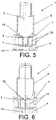
- Figure 6 shows the capsule (1) completely closed without the connecting element (2) therein. It is then when by means of the insertion actuators (17) the force exerted by the closure means (11) is overcome, these closure means (11) being able to be magnets or preloaded springs (not shown in the figures) that actuate the cover (8) to keep it closed, thus overcoming said force of the closure means (11) the cover (8) is opened. As can be seen in figure 4 , the opening of the petals (9) is achieved to make way for the insertion of the connecting element (2).
- clamping elements (5) must be opened. These clamping elements (5) are configured to hold the connecting element (2).
- Each clamping element (5) has a clamping axis (6) parallel to the guiding direction (4), the clamping axis (6) being able to be perpendicular in an optional embodiment.
- the clamping element (5) due to the pivoting thereof and the thrust caused by tightening means (10) is normally actuated and therefore closed, as can be seen in figures 4 , 6 and 7 .
- each clamping element (5) comprises a magnet in contrast to a magnet comprised in the capsule (1), both being of the same opposite polarity to generate the required repulsion force, thus representing the tightening means (10). In this way they repel each other, the clamping elements (5) being in the closed position in the absence of the connecting element (2) ( figures 4 , 6 and 7 ).
- the connecting element (2) is adjusted by the pushing pressure exerted by the clamping elements (5) due to the magnets (10). This thrust occurs in the radial direction of the connecting element (2) and due to the pivoting of the clamping elements (5) a diametrical adjustment to the connecting element (2) occurs that prevents the movement thereof both radially and axially.
- the cover (8) in addition to protecting, also serves as an additional support for connecting elements (2) of great lengths.
- the cover (8) limits this tilt and the force of the clamping elements (5) exert the force required to bring the connecting element (2) back to the initial position thereof, once the inertial forces have disappeared.
- a grooved surface (19) is optionally on the contact surface of the clamping element (5) with the connecting element (2). This improves the mooring, immobilising the connecting element (2) with greater safety.
- each clamping element (5) presses on at least one isolated area of the connecting element (2), preferably a line of the connecting element (2), this isolated area of the axis of the connecting element (2) being able to be selected between an isolated area of the stem of a blind rivet, an isolated area of the stem of a temporary clamp, an isolated area of the thread of a sleeve rivet and an isolated area of the thread of a screw, and it can be any other connecting element (2) that has a central axis. Therefore, it provides the capsule (1) with a versatility of use for different types of connecting elements (2) and of different sizes that gives the installation a greater speed for placing connecting elements (2) since it does not have to change the type of capsule (1) or head when different types of rivets are continuously required.
- the clamping element (5) comprises a rib (7) in the lower portion of the contact surface with the connecting element (2).
- an axial stop is provided that provides additional support to the connecting element (2) which will rest at the lower end thereof on said rib (7) ( figure 5 ).
- the capsule comprises at least two clamping elements (5) spaced axially apart and preferably three clamping elements (5) pressing on an isolated area of the axis of the connecting element (2) and three other clamping elements (5) pressing on a point area axially distanced from the previous one.
- an additional adjustment for connecting elements (2) is achieved which, due to the dimensions thereof, have greater weight and therefore greater inertia.
- Figure 9 shows the use of the capsule (1) for temporary clamps instead of the standard rivets.
- the aforementioned versatility is demonstrated, however, both for these temporary clamps (2) and for connecting elements (2) wherein the axis has a longer longitudinal dimension, there would be problems for housing the connecting element (2) that would interfere with the lower portion of the capsule. Therefore, an additional feature of the invention is that it comprises a through opening (15) to allow the passage of said special connecting elements (2).
- the capsule (1) is transferred in the guide duct (3) to the application machine (14) by means of pressurised air, moving it up to the application head according to the guiding direction (4) ( figures 2 and 11 ).
- the capsule (1) Once the capsule (1) reaches the limit switch of the guide duct (3), the capsule (1) is positioned in front of the application machine (14). The capsule (1) is then aligned in the same way as in the application machine (13) thanks to the orientation means (12) located in the lower portion of the capsule (1).
- the tightening means (10) and the closure means (11) are pressed on again, as in the supply step, by means of preferably pneumatic extraction actuators (18). Then an extraction arm extracts the connecting element (2) to place it in an application head for the final placement thereof.
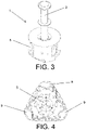
- Figure 3 shows an optional exemplary embodiment of the capsule (1) wherein the connecting element (2) is completely held both radially and axially by the clamping elements (5) being partially housed therein.
- the connecting element (2) is arranged completely covered laterally without being covered at the upper portion thereof.
- This embodiment is applicable to connecting elements (2) of small longitudinal dimensions and to connecting elements (2) that do not require the application of a sealant.
Landscapes
- Engineering & Computer Science (AREA)
- Mechanical Engineering (AREA)
- Physics & Mathematics (AREA)
- Fluid Mechanics (AREA)
- Medical Preparation Storing Or Oral Administration Devices (AREA)
- Insertion Pins And Rivets (AREA)
Applications Claiming Priority (2)
| Application Number | Priority Date | Filing Date | Title |
|---|---|---|---|
| ES202030090A ES2848248B2 (es) | 2020-02-05 | 2020-02-05 | Capsula de transporte de elementos de union e instalacion de colocacion de los mismos |
| PCT/ES2021/070081 WO2021156534A1 (es) | 2020-02-05 | 2021-02-03 | Capsula de transporte de elementos de union e instalacion de colocacion de los mismos |
Publications (2)
| Publication Number | Publication Date |
|---|---|
| EP4101559A1 true EP4101559A1 (de) | 2022-12-14 |
| EP4101559A4 EP4101559A4 (de) | 2024-03-13 |
Family
ID=77125089
Family Applications (1)
| Application Number | Title | Priority Date | Filing Date |
|---|---|---|---|
| EP21750186.5A Withdrawn EP4101559A4 (de) | 2020-02-05 | 2021-02-03 | Kapsel zum transport von verbindungselementen und anlage zum platzieren derselben |
Country Status (3)
| Country | Link |
|---|---|
| EP (1) | EP4101559A4 (de) |
| ES (1) | ES2848248B2 (de) |
| WO (1) | WO2021156534A1 (de) |
Cited By (1)
| Publication number | Priority date | Publication date | Assignee | Title |
|---|---|---|---|---|
| EP4667149A3 (de) * | 2024-05-30 | 2026-02-18 | The Boeing Company | Automatisiertes befestigungssystem und verfahren mit automatisierter unterlegscheibeninstallation und verfahren zur verwendung einer leitfähigen unterlegscheibe |
Family Cites Families (10)
| Publication number | Priority date | Publication date | Assignee | Title |
|---|---|---|---|---|
| GB2180482B (en) * | 1985-09-19 | 1989-01-25 | Avdel Ltd | Apparatus for installing fasteners |
| JPH01176039A (ja) | 1987-12-29 | 1989-07-12 | Fuji Denshi Kogyo Kk | クランクシャフトの高周波表面焼入法 |
| JPH09118433A (ja) * | 1995-10-26 | 1997-05-06 | Ueno Seisakusho:Kk | 気送子 |
| EP1116678B1 (de) * | 2000-01-11 | 2005-04-27 | Peter Schindler | Handhabungsverfahren zum positionsgenauen Transportieren eines Werkstückes |
| JP4437588B2 (ja) * | 2000-03-23 | 2010-03-24 | 日本飛行機株式会社 | 鋲輸送用スリーブおよび鋲輸送方法 |
| AU2001269744A1 (en) * | 2000-06-17 | 2002-01-02 | Textron Inc. | Rivet carrier |
| GB2429183B (en) * | 2005-08-20 | 2009-06-17 | Textron Fastening Syst Ltd | Shuttle and component feeding system |
| JP5207059B2 (ja) * | 2008-12-15 | 2013-06-12 | ポップリベット・ファスナー株式会社 | スタッド溶接装置 |
| US9266687B2 (en) * | 2013-06-24 | 2016-02-23 | The Boeing Company | Systems and methods for delivery of devices along a transport path |
| GB2569127A (en) * | 2017-12-05 | 2019-06-12 | Atlas Copco Ias Uk Ltd | Nose arrangements for fastener setting machines, and related methods |
-
2020
- 2020-02-05 ES ES202030090A patent/ES2848248B2/es not_active Expired - Fee Related
-
2021
- 2021-02-03 EP EP21750186.5A patent/EP4101559A4/de not_active Withdrawn
- 2021-02-03 WO PCT/ES2021/070081 patent/WO2021156534A1/es not_active Ceased
Cited By (1)
| Publication number | Priority date | Publication date | Assignee | Title |
|---|---|---|---|---|
| EP4667149A3 (de) * | 2024-05-30 | 2026-02-18 | The Boeing Company | Automatisiertes befestigungssystem und verfahren mit automatisierter unterlegscheibeninstallation und verfahren zur verwendung einer leitfähigen unterlegscheibe |
Also Published As
| Publication number | Publication date |
|---|---|
| EP4101559A4 (de) | 2024-03-13 |
| ES2848248A1 (es) | 2021-08-05 |
| ES2848248B2 (es) | 2021-12-16 |
| WO2021156534A1 (es) | 2021-08-12 |
Similar Documents
| Publication | Publication Date | Title |
|---|---|---|
| DK2607029T3 (en) | TOOL CHANGE SYSTEM | |
| US8653402B2 (en) | Joining system head, joining system, and method of feeding and joining elements | |
| EP2640536B1 (de) | Verfahren und vorrichtung zum zuführen von verbindungselementen | |
| EP4101559A1 (de) | Kapsel zum transport von verbindungselementen und anlage zum platzieren derselben | |
| US7060930B2 (en) | Joining system head, joining system, and method of feeding and joining elements | |
| EP3162507B1 (de) | Magnetschwebeschraubenklemmbacke für automatische schraubendreher | |
| EP3037190B1 (de) | Greifvorrichtung für Befestigungselemente | |
| US10183366B2 (en) | Feeder mechanism for feeding mechanical fasteners | |
| US20120192612A1 (en) | Pipe manipulator | |
| US20160288198A1 (en) | Interchangeable die transfer station, joining tool system and joining method | |
| CN108857540A (zh) | 夹爪结构及具有其的夹具 | |
| EP3619157B1 (de) | Vorrichtung zum greifen und zentrieren von flaschen für verschliessanlagen | |
| EP2647455B1 (de) | Vorrichtung zur befestigung eines werkstücks in einem maschinenwerkzeug und maschinenwerkzeug mit der befestigungsvorrichtung | |
| EP0919516B1 (de) | Vorrichtung zum Anbringen von Verschlusskappen | |
| US20080295331A1 (en) | Method and Apparatus for Inserting a Piston Pin Locking Ring | |
| ES2412490T3 (es) | Dispositivo de selección y de fijación de remaches | |
| EP0965764B1 (de) | Feder- Verriegelungsvorrichtung | |
| GB2337018A (en) | Seal extraction tool | |
| CN106272155B (zh) | 自动夹持套件 | |
| US5901444A (en) | Assist method for fitting close tolerance valves into bores | |
| CN221986826U (zh) | 一种用于对容器进行贴标的贴标装置 | |
| JP6979762B2 (ja) | グリッパ | |
| KR102810621B1 (ko) | 자기 작동 기계적 편향 용기 유지기 | |
| CN115052719B (zh) | 手装置以及工件处理系统 | |
| WO2010007575A2 (en) | Device for use in molecular diagnostics testing |
Legal Events
| Date | Code | Title | Description |
|---|---|---|---|
| STAA | Information on the status of an ep patent application or granted ep patent |
Free format text: STATUS: THE INTERNATIONAL PUBLICATION HAS BEEN MADE |
|
| PUAI | Public reference made under article 153(3) epc to a published international application that has entered the european phase |
Free format text: ORIGINAL CODE: 0009012 |
|
| STAA | Information on the status of an ep patent application or granted ep patent |
Free format text: STATUS: REQUEST FOR EXAMINATION WAS MADE |
|
| 17P | Request for examination filed |
Effective date: 20220905 |
|
| AK | Designated contracting states |
Kind code of ref document: A1 Designated state(s): AL AT BE BG CH CY CZ DE DK EE ES FI FR GB GR HR HU IE IS IT LI LT LU LV MC MK MT NL NO PL PT RO RS SE SI SK SM TR |
|
| DAV | Request for validation of the european patent (deleted) | ||
| DAX | Request for extension of the european patent (deleted) | ||
| P01 | Opt-out of the competence of the unified patent court (upc) registered |
Effective date: 20230519 |
|
| REG | Reference to a national code |
Ref country code: DE Ref legal event code: R079 Free format text: PREVIOUS MAIN CLASS: B21J0015320000 Ipc: B65G0051040000 |
|
| A4 | Supplementary search report drawn up and despatched |
Effective date: 20240212 |
|
| RIC1 | Information provided on ipc code assigned before grant |
Ipc: B65G 51/06 20060101ALN20240207BHEP Ipc: B23K 9/20 20060101ALN20240207BHEP Ipc: B21J 15/32 20060101ALN20240207BHEP Ipc: B23P 19/00 20060101ALI20240207BHEP Ipc: B65G 51/04 20060101AFI20240207BHEP |
|
| STAA | Information on the status of an ep patent application or granted ep patent |
Free format text: STATUS: THE APPLICATION IS DEEMED TO BE WITHDRAWN |
|
| 18D | Application deemed to be withdrawn |
Effective date: 20240830 |