EP4101594A1 - Machine-outil et procédé de fonctionnement d'une machine-outil - Google Patents
Machine-outil et procédé de fonctionnement d'une machine-outil Download PDFInfo
- Publication number
- EP4101594A1 EP4101594A1 EP21178467.3A EP21178467A EP4101594A1 EP 4101594 A1 EP4101594 A1 EP 4101594A1 EP 21178467 A EP21178467 A EP 21178467A EP 4101594 A1 EP4101594 A1 EP 4101594A1
- Authority
- EP
- European Patent Office
- Prior art keywords
- machine tool
- motor
- tool
- range
- speed
- Prior art date
- Legal status (The legal status is an assumption and is not a legal conclusion. Google has not performed a legal analysis and makes no representation as to the accuracy of the status listed.)
- Withdrawn
Links
Images

Classifications
-
- B—PERFORMING OPERATIONS; TRANSPORTING
- B25—HAND TOOLS; PORTABLE POWER-DRIVEN TOOLS; MANIPULATORS
- B25F—COMBINATION OR MULTI-PURPOSE TOOLS NOT OTHERWISE PROVIDED FOR; DETAILS OR COMPONENTS OF PORTABLE POWER-DRIVEN TOOLS NOT PARTICULARLY RELATED TO THE OPERATIONS PERFORMED AND NOT OTHERWISE PROVIDED FOR
- B25F5/00—Details or components of portable power-driven tools not particularly related to the operations performed and not otherwise provided for
- B25F5/001—Gearings, speed selectors, clutches or the like specially adapted for rotary tools
-
- B—PERFORMING OPERATIONS; TRANSPORTING
- B25—HAND TOOLS; PORTABLE POWER-DRIVEN TOOLS; MANIPULATORS
- B25F—COMBINATION OR MULTI-PURPOSE TOOLS NOT OTHERWISE PROVIDED FOR; DETAILS OR COMPONENTS OF PORTABLE POWER-DRIVEN TOOLS NOT PARTICULARLY RELATED TO THE OPERATIONS PERFORMED AND NOT OTHERWISE PROVIDED FOR
- B25F5/00—Details or components of portable power-driven tools not particularly related to the operations performed and not otherwise provided for
Definitions
- the invention relates to a machine tool with a tool and a motor, with the motor of the machine tool being operated in a speed range from 2,000 to 30,000 rpm and with an inertia of the motor in a range from 20 10 -6 to 750 10 -6 kg. m 2 lies.
- the invention relates to a method for operating a machine tool that is operated in a speed range of 2,000 to 30,000 rpm, the inertia of the motor being in a range of 20 ⁇ 10 -6 to 750*10 -6 kg*m 2 .
- the machine tool By selecting and specifying a set of parameters that describe characteristics of the machine tool's motor, the machine tool can be designed and operated in such a way that a mechanical slip clutch can be dispensed with.
- the motor parameters "speed" and “inertia” are selected in particular in such a way that a maximum torque in a gear of the machine tool is always below a specified upper limit.
- the invention enables particularly productive work with the machine tool, with tests having shown that the service intervals can advantageously be extended by omitting the mechanical slip clutch.
- hammer drills chisels, cutters or angle grinders, screwing devices or core drilling devices are known, in each of which a tool is driven by a motor.
- a power supply can be provided via a mains connection or with batteries or accumulators ("accumulators").
- the object of the present invention is therefore to overcome the above-described deficiencies and disadvantages of the prior art and to provide an improved machine tool and a method for operating a machine tool in which the peak torque can be limited if the tool is blocked or jammed. It is a further concern of the invention that the machine tool should manage without a mechanical slipping clutch, with no compromises being made in terms of protecting the user of the machine tool. In addition, a compact and lightweight machine tool is to be made available, which enables convenient handling and is particularly low-maintenance.
- the object is achieved in a first aspect by a machine tool with a tool and a motor, the motor in a speed range of 2,000 to 30,000 rpm is operable, wherein an inertia of the motor is in a range of 20 ⁇ 10 -6 to 750 ⁇ 10 -6 kg ⁇ m 2 .
- the abbreviation rpm stands for the unit rounds per minutes, ie for the number of revolutions per minute.
- the inventors have recognized that the magnitude of the torque peaks that occur when the tool of the machine tool jams or blocks depends on the inertia conditions within the machine tool.
- the invention is based on the idea that the level of the maximum torque can be adjusted and limited by skillful selection of engine parameters such that the maximum torque does not exceed a predetermined upper limit value.
- the upper limit represents a maximum value for the torque that can be achieved by the machine tool or its motor.
- the maximum torque in the drive train of the machine tool is reached in particular when the tool of the machine tool is jammed or blocked.
- the high torque values that then occur are preferably referred to as “torque peaks” within the meaning of the invention.
- torque peaks within the meaning of the invention.
- the inventors have recognized that the maximum torque depends on the inertia ratios between the machine tool and its motor, as well as on the stalling speed of the tool and on the rigidity in the drive train of the machine tool.
- the maximum torque that occurs can be limited and kept below an upper limit value if the machine tool is operated in a motor speed range of 2,000 to 30,000 rpm and the inertia of the motor of the machine tool is in a range of 20 ⁇ 10 -6 to 750 ⁇ 10 -6 kg ⁇ m 2 .
- the invention consists in particular in specifying the parameter ranges of motor speed and motor inertia mentioned, so that the maximum torque of the motor of the machine tool always remains below a specified upper limit. This makes it possible for the user of the machine tool to operate the machine tool in a particularly safe manner.
- the time in which a jammed or blocked tool of a machine tool comes to a standstill is usually very short.
- the corresponding period of time can be in the range of 5 milliseconds (ms), for example.
- the machine tool preferably continues to rotate at a predetermined initial speed. This movement is perceived by the user of the machine tool as a deflection of the machine tool. Tests have shown that this deflection of the machine tool, which in the past has often led to injuries in the arm, shoulder and hand area of a user, can be significantly reduced with the invention.
- the proposed machine tool can in particular be a core drilling device.
- the tool of the machine tool is then preferably designed as a drill bit.
- the core bit is used to cut out cylindrical cores from solid ground.
- the proposed machine tool can also be, for example, a hammer drill or drill/screwdriver.
- a range for the motor inertia is described in the context of the invention, which allows slip clutch-free operation of the machine tool in the speed range that is also specified.
- the invention makes it possible to dispense with a mechanical slipping clutch, so that the machine tool can be manufactured more cost-effectively and made more compact. This advantageously leads to particularly convenient and simplified handling of the machine tool.
- a productivity-enhanced and low-maintenance machine tool with longer service intervals can be provided.
- motor inertia is understood as the mass moment of inertia of the motor, in particular as the mass moment of inertia of the rotating components of the motor about the axis of rotation of the motor shaft.
- the rotating components of the motor which preferably rotate about the axis of rotation of the motor shaft, are preferably the rotor of the motor.
- inertia of the machine tool is preferably understood as the mass moment of inertia of the machine tool, with the rotating components of the machine tool preferably rotating about the axis of rotation of the tool.
- the upper limit for the torque is in a range from 500 to 1,500 Nm, preferably in a range from 700 to 1,200 Nm, particularly preferably in a range from 850 to 950 Nm and most preferably 900 Nm. It is preferred within the meaning of the invention that the level of the permitted maximum torque values is based on the robustness of the transmission of the machine tool. The inventors have recognized that the tangential component of the acceleration of the side handle of the machine tool also plays a role in the maximum torque. In the context of this invention, this tangential component of the acceleration is referred to as the so-called “level of pain” (LOP).
- LOP level of pain
- this acceleration component is used as a measure of the ease of use of the machine tool in the event of the tool of the machine tool becoming blocked.
- the inventors have recognized that the pain measure with is related to the maximum torque or its torque peaks. This relationship results in particular from the inertia of the machine tool. There is therefore a connection between the maximum permissible speed and the torque peaks within the machine tool. Limiting the torque to values below an upper limit value therefore advantageously also limits the degree of pain and improves the ease of use of the machine tool compared to conventional machine tools, as are known from the prior art.
- the machine tool has a gear with a transmission ratio.
- the translation preferably results from the motor characteristic, ie the characteristic of the motor of the machine tool. It is preferred within the meaning of the invention that the motor characteristic describes the lowest speed value at which the motor of the machine tool can provide the required power.
- the gear ratio is also reflected in particular in the time lag between the standstill of the tool and the standstill of the motor of the machine tool when the tool of the machine tool jams or blocks. For example, while the tool stall time is in the range of 5 ms, the machine tool motor stall time may be in the range of 50 ms.
- the subject matter of the present invention is, in particular, the processes during the stated time periods after the tool of the machine tool has jammed. These periods of time will 1 referred to as the second and third periods.
- the degree of pain, the ease of use and the maximum torque can depend on the engine parameters speed, rotor inertia and/or peak torque.
- the inertia of the machine tool is in a range from 30,000*10 -6 to 70,000*10 -6 kg*m 2 , preferably in a range from 40,000*10 -6 to 60,000*10 -6 kg ⁇ m 2 , more preferably in a range from 45,000 ⁇ 10 -6 to 55,000 ⁇ 10 -6 kg ⁇ m 2 and most preferably at 50,000 ⁇ 10 -6 kg ⁇ m 2 .
- the values mentioned for the inertia of the machine tool are preferably used as input variables for determining the motor parameters speed and motor inertia.
- the machine tool can have a spindle, with which a rotation of the motor is transmitted to the tool of the machine tool.
- the speed of the spindle can be in a range from 1000 to 1500 rpm, preferably 1250 to 1350 rpm and particularly preferably 1300 rpm.
- the speed of the spindle corresponds to the speed of the tool of the proposed machine tool.
- the tool of the machine tool preferably rotates at a speed in a range from 1,000 to 1,500 rpm, preferably in a range from 1,250 to 1,350 rpm and particularly preferably at a speed of approx. 1,300 rpm.
- the speed of the spindle or the speed of the tool of the machine tool is coupled to the speed of the engine via the transmission ratio in the gearbox, with the transmission ratio playing an important role for the effective moment of inertia.
- the invention in a second aspect, relates to a method for operating a machine tool.
- the machine tool has a tool and a motor, with the motor of the machine tool being operated in a speed range of 2,000 to 30,000 rpm and with an inertia of the motor in a range of 20 ⁇ 10 -6 to 750*10 -6 kg*m 2 .
- the definitions, technical effects and advantages described for the proposed machine tool apply analogously to the proposed operating method.
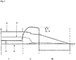
- the first period of time I. relates to the normal operation of the machine tool (10), during which work is carried out with the machine tool (10).
- the variables (1-4) shown are essentially constant, with such an approximately constant course of the variables (1-4) not excluding fluctuations and deviations from a mean value.
- the machine tool (10) is a core drill, for example, cylindrical cores can be cut out of solid ground with the drill bit (11).
- the drill bit as a tool (11) of the machine tool (10) is driven by a motor (12) of the machine tool (10).
- the movement from the motor (12) to the tool (11) can be transmitted by means of a spindle (14).
- the machine tool (10) can also include a gear (13). in the in 2 illustrated embodiment of the invention, the core drilling device (10) is attached to a drill stand, the invention can also be used in particular in hand-held machine tools.
- the second period of time II begins with the blocking of the tool (11) of the machine tool (10).
- the start of the blockage of the tool (11) of the machine tool (10) is in 1 shown with the first dashed vertical straight line.
- the speeds of motor (1) and tool (2) fall, while the torque (3) rises sharply.
- the second period of time II lasts for example 5 ms.
- the end of the second period of time II is determined by the tool (11) of the machine tool (10) coming to a standstill.
- the motor (12) of the machine tool (10) requires more time to be completely braked, the standstill of the motor (12) of the machine tool (10) marking the end of the third period of time III. determines.
- the time offset between standstill of the tool (11) and the motor (12) is determined by the transmission ratio of the gear (13) of the machine tool (10).
- the torque (3) assumes its highest value (5), which at the same time represents the upper limit (5) of the torque (3).
- This upper limit (5) of the torque (3) is given in 1 by the block arrow pointing up at the top right of 1 implied.
- a movement or deflection (4) of the machine tool (10) itself can also occur in the middle of the second period of time II. In the past, this deflection has led to injuries to the arms, shoulders or wrists of users of the machine tool (10), which is why it is a concern of the present invention to minimize this deflection (4).
- the machine tool (10) or its drive begins to brake. This falls in the third period III. the torque (3) decreases significantly.
- the transition between the second time span II. and the third time span III. is in 1 shown with the second dashed vertical straight line.
- the speed (1) of the motor (12) of the machine tool (10) also falls in the third period III., the drop in motor speed (1) occurring approximately linearly until the motor (12) at the end of the third period III. has come to a complete standstill.
- the deflection (4) of the machine tool (10) is in the third time period III. stopped.
- the third period III. can last for example 50 ms.
Landscapes
- Engineering & Computer Science (AREA)
- Mechanical Engineering (AREA)
- Control Of Electric Motors In General (AREA)
- Percussive Tools And Related Accessories (AREA)
- Portable Power Tools In General (AREA)
- Connection Of Motors, Electrical Generators, Mechanical Devices, And The Like (AREA)
Priority Applications (6)
| Application Number | Priority Date | Filing Date | Title |
|---|---|---|---|
| EP21178467.3A EP4101594A1 (fr) | 2021-06-09 | 2021-06-09 | Machine-outil et procédé de fonctionnement d'une machine-outil |
| PCT/EP2022/064018 WO2022258362A1 (fr) | 2021-06-09 | 2022-05-24 | Machine-outil et procédé d'actionnement d'une machine-outil |
| US18/560,789 US12384010B2 (en) | 2021-06-09 | 2022-05-24 | Power tool and method for operating a power tool |
| CN202280028936.8A CN117203023A (zh) | 2021-06-09 | 2022-05-24 | 动力工具以及用于操作动力工具的方法 |
| EP22730249.4A EP4351839B1 (fr) | 2021-06-09 | 2022-05-24 | Machine-outil et procédé de fonctionnement d'une machine-outil |
| JP2023563836A JP7811951B2 (ja) | 2021-06-09 | 2022-05-24 | 機械工具及び機械工具を動作させる方法 |
Applications Claiming Priority (1)
| Application Number | Priority Date | Filing Date | Title |
|---|---|---|---|
| EP21178467.3A EP4101594A1 (fr) | 2021-06-09 | 2021-06-09 | Machine-outil et procédé de fonctionnement d'une machine-outil |
Publications (1)
| Publication Number | Publication Date |
|---|---|
| EP4101594A1 true EP4101594A1 (fr) | 2022-12-14 |
Family
ID=76355365
Family Applications (2)
| Application Number | Title | Priority Date | Filing Date |
|---|---|---|---|
| EP21178467.3A Withdrawn EP4101594A1 (fr) | 2021-06-09 | 2021-06-09 | Machine-outil et procédé de fonctionnement d'une machine-outil |
| EP22730249.4A Active EP4351839B1 (fr) | 2021-06-09 | 2022-05-24 | Machine-outil et procédé de fonctionnement d'une machine-outil |
Family Applications After (1)
| Application Number | Title | Priority Date | Filing Date |
|---|---|---|---|
| EP22730249.4A Active EP4351839B1 (fr) | 2021-06-09 | 2022-05-24 | Machine-outil et procédé de fonctionnement d'une machine-outil |
Country Status (5)
| Country | Link |
|---|---|
| US (1) | US12384010B2 (fr) |
| EP (2) | EP4101594A1 (fr) |
| JP (1) | JP7811951B2 (fr) |
| CN (1) | CN117203023A (fr) |
| WO (1) | WO2022258362A1 (fr) |
Citations (5)
| Publication number | Priority date | Publication date | Assignee | Title |
|---|---|---|---|---|
| US3714994A (en) * | 1971-11-29 | 1973-02-06 | Gardner Denver Co | Fluid actuated impact mechanism |
| US6009775A (en) * | 1996-11-26 | 2000-01-04 | Titan Tool Company | Wrench with high inertia torque system and method for using same |
| WO2011122695A1 (fr) * | 2010-03-31 | 2011-10-06 | Hitachi Koki Co., Ltd. | Outil électrique |
| EP3753396A1 (fr) * | 2019-06-18 | 2020-12-23 | Globe (Jiangsu) Co., Ltd. | Tondeuse |
| WO2021084315A1 (fr) * | 2019-10-31 | 2021-05-06 | Dino Paoli S.R.L. | Ensemble de liaison douille-arbre d'une clé à impact pneumatique |
Family Cites Families (13)
| Publication number | Priority date | Publication date | Assignee | Title |
|---|---|---|---|---|
| JP2008213087A (ja) | 2007-03-02 | 2008-09-18 | Matsushita Electric Works Ltd | 電動工具制御システム |
| US7960931B2 (en) * | 2007-06-15 | 2011-06-14 | Illinois Institute Of Technology | Digital control of motor drives |
| DK177641B1 (en) * | 2010-04-29 | 2014-01-20 | Hilti Ag | A power tool |
| JP5534328B2 (ja) | 2010-05-31 | 2014-06-25 | 日立工機株式会社 | 電動工具 |
| DE102010032335A1 (de) * | 2010-07-20 | 2012-01-26 | C. & E. Fein Gmbh | Handwerkzeug |
| JP5686236B2 (ja) * | 2010-07-30 | 2015-03-18 | 日立工機株式会社 | 電動工具及びネジ締め用電動工具 |
| JP6148609B2 (ja) * | 2013-11-21 | 2017-06-14 | 株式会社マキタ | 電動工具 |
| CN203843805U (zh) * | 2014-05-30 | 2014-09-24 | 浙江绿动电机科技有限公司 | 一种同轴式电动工具 |
| JP2016221621A (ja) * | 2015-05-29 | 2016-12-28 | 日立工機株式会社 | 電動工具 |
| DE202016104106U1 (de) * | 2015-08-07 | 2016-10-09 | Hitachi Koki Co., Ltd. | Elektrowerkzeug |
| JP6638522B2 (ja) * | 2015-08-07 | 2020-01-29 | 工機ホールディングス株式会社 | 電動工具 |
| JP2019155533A (ja) * | 2018-03-13 | 2019-09-19 | 株式会社マキタ | ネジ締め工具 |
| CN209408417U (zh) * | 2018-06-05 | 2019-09-20 | 南京德朔实业有限公司 | 动力工具 |
-
2021
- 2021-06-09 EP EP21178467.3A patent/EP4101594A1/fr not_active Withdrawn
-
2022
- 2022-05-24 JP JP2023563836A patent/JP7811951B2/ja active Active
- 2022-05-24 US US18/560,789 patent/US12384010B2/en active Active
- 2022-05-24 EP EP22730249.4A patent/EP4351839B1/fr active Active
- 2022-05-24 WO PCT/EP2022/064018 patent/WO2022258362A1/fr not_active Ceased
- 2022-05-24 CN CN202280028936.8A patent/CN117203023A/zh active Pending
Patent Citations (5)
| Publication number | Priority date | Publication date | Assignee | Title |
|---|---|---|---|---|
| US3714994A (en) * | 1971-11-29 | 1973-02-06 | Gardner Denver Co | Fluid actuated impact mechanism |
| US6009775A (en) * | 1996-11-26 | 2000-01-04 | Titan Tool Company | Wrench with high inertia torque system and method for using same |
| WO2011122695A1 (fr) * | 2010-03-31 | 2011-10-06 | Hitachi Koki Co., Ltd. | Outil électrique |
| EP3753396A1 (fr) * | 2019-06-18 | 2020-12-23 | Globe (Jiangsu) Co., Ltd. | Tondeuse |
| WO2021084315A1 (fr) * | 2019-10-31 | 2021-05-06 | Dino Paoli S.R.L. | Ensemble de liaison douille-arbre d'une clé à impact pneumatique |
Also Published As
| Publication number | Publication date |
|---|---|
| EP4351839A1 (fr) | 2024-04-17 |
| JP7811951B2 (ja) | 2026-02-06 |
| EP4351839B1 (fr) | 2026-02-18 |
| US12384010B2 (en) | 2025-08-12 |
| WO2022258362A1 (fr) | 2022-12-15 |
| JP2024514905A (ja) | 2024-04-03 |
| US20240278407A1 (en) | 2024-08-22 |
| CN117203023A (zh) | 2023-12-08 |
Similar Documents
| Publication | Publication Date | Title |
|---|---|---|
| EP2338646B1 (fr) | Procédé de commande pour une machine-outil manuelle | |
| DE102010062014B3 (de) | Handwerkzeugmaschine | |
| EP1049416B1 (fr) | DISPOSITIF D'ENTRAINEMENT POUR INSTRUMENTS DE PERçAGE, D'INCISION ET DE VISSAGE À USAGE MÉDICAL | |
| EP1993765A1 (fr) | Couplage commutable pour un outil électronique manuel | |
| DE2944275A1 (de) | Motorisch betriebenes handwerkzeug | |
| DE10033100A1 (de) | Kombiniertes Elektrohandwerkzeuggerät | |
| DE102011004126A1 (de) | Handwerkzeugmaschine mit einem Untersetzungsgetriebe | |
| EP2794194A2 (fr) | Machine-outil comprenant un dispositif pour passer entre un premier et un deuxième rapport d'engrenage par inversion du sens de rotation | |
| EP2861382A1 (fr) | Transmission | |
| EP3288734A1 (fr) | Génération adaptative de paramètres de forage lors d'une opération de carottage automatisé | |
| DE69513091T2 (de) | Zahnärztliches Behandlungswerkzeug zur Herstellung von einem Schraubenloch zum Einbau von Implantatmaterial | |
| EP4351839B1 (fr) | Machine-outil et procédé de fonctionnement d'une machine-outil | |
| EP3756823A1 (fr) | Procédé de détection d'un état d'une machine-outil ainsi que machine-outil | |
| EP4665537A1 (fr) | Machine-outil ayant un outil et procédé de fonctionnement de la machine-outil | |
| DE102005037254A1 (de) | Elektrowerkzeugmaschine sowie Überlastschutzvorrichtung | |
| WO2023094381A1 (fr) | Marteau perforateur vibrant | |
| DE19820640A1 (de) | Verfahren zur Überwachung des Zustands eines medizinischen Werkzeugs | |
| EP4289534A1 (fr) | Procédé permettant de faire fonctionner une machine-outil ayant des caractéristiques différentes d'appareil et de moteur | |
| DE687531C (de) | Kraftbetriebene Handwerkzeugmaschine, insbesondereine | |
| DE524142C (de) | Drehend arbeitendes Werkzeug mit Raedergetriebe mit zwei zwischen der Antriebsspindel und der Werkzeugspindel angeordneten Kupplungen | |
| WO2021089603A1 (fr) | Procédé et dispositif de coupe de tranchée destinés à la création d'une tranchée dans le sol | |
| DE102018201074A1 (de) | Verfahren zur Steuerung eines Schlagschraubers | |
| WO2023237364A1 (fr) | Procédé pour faire fonctionner une machine-outil et machine-outil | |
| EP4484042A1 (fr) | Procédé et outil électrique pour le formage de filets | |
| DE102013218318B3 (de) | Vorrichtung zur Begrenzung eines von einem Schraubwerkzeug übertragbaren Drehmoments |
Legal Events
| Date | Code | Title | Description |
|---|---|---|---|
| PUAI | Public reference made under article 153(3) epc to a published international application that has entered the european phase |
Free format text: ORIGINAL CODE: 0009012 |
|
| STAA | Information on the status of an ep patent application or granted ep patent |
Free format text: STATUS: THE APPLICATION HAS BEEN PUBLISHED |
|
| AK | Designated contracting states |
Kind code of ref document: A1 Designated state(s): AL AT BE BG CH CY CZ DE DK EE ES FI FR GB GR HR HU IE IS IT LI LT LU LV MC MK MT NL NO PL PT RO RS SE SI SK SM TR |
|
| STAA | Information on the status of an ep patent application or granted ep patent |
Free format text: STATUS: THE APPLICATION IS DEEMED TO BE WITHDRAWN |
|
| 18D | Application deemed to be withdrawn |
Effective date: 20230615 |