EP4101604A1 - System und verfahren zur verbesserung der genauigkeit der 3d-augen-hand-koordination eines robotersystems - Google Patents
System und verfahren zur verbesserung der genauigkeit der 3d-augen-hand-koordination eines robotersystems Download PDFInfo
- Publication number
- EP4101604A1 EP4101604A1 EP22176286.7A EP22176286A EP4101604A1 EP 4101604 A1 EP4101604 A1 EP 4101604A1 EP 22176286 A EP22176286 A EP 22176286A EP 4101604 A1 EP4101604 A1 EP 4101604A1
- Authority
- EP
- European Patent Office
- Prior art keywords
- pose
- robotic
- component
- machine
- robotic arm
- Prior art date
- Legal status (The legal status is an assumption and is not a legal conclusion. Google has not performed a legal analysis and makes no representation as to the accuracy of the status listed.)
- Withdrawn
Links
Images



Classifications
-
- B—PERFORMING OPERATIONS; TRANSPORTING
- B25—HAND TOOLS; PORTABLE POWER-DRIVEN TOOLS; MANIPULATORS
- B25J—MANIPULATORS; CHAMBERS PROVIDED WITH MANIPULATION DEVICES
- B25J9/00—Program-controlled manipulators
- B25J9/16—Program controls
-
- B—PERFORMING OPERATIONS; TRANSPORTING
- B25—HAND TOOLS; PORTABLE POWER-DRIVEN TOOLS; MANIPULATORS
- B25J—MANIPULATORS; CHAMBERS PROVIDED WITH MANIPULATION DEVICES
- B25J9/00—Program-controlled manipulators
- B25J9/16—Program controls
- B25J9/1679—Program controls characterised by the tasks executed
- B25J9/1692—Calibration of manipulator
-
- B—PERFORMING OPERATIONS; TRANSPORTING
- B25—HAND TOOLS; PORTABLE POWER-DRIVEN TOOLS; MANIPULATORS
- B25J—MANIPULATORS; CHAMBERS PROVIDED WITH MANIPULATION DEVICES
- B25J9/00—Program-controlled manipulators
- B25J9/16—Program controls
- B25J9/1602—Program controls characterised by the control system, structure, architecture
- B25J9/161—Hardware, e.g. neural networks, fuzzy logic, interfaces, processor
-
- B—PERFORMING OPERATIONS; TRANSPORTING
- B25—HAND TOOLS; PORTABLE POWER-DRIVEN TOOLS; MANIPULATORS
- B25J—MANIPULATORS; CHAMBERS PROVIDED WITH MANIPULATION DEVICES
- B25J9/00—Program-controlled manipulators
- B25J9/16—Program controls
- B25J9/1628—Program controls characterised by the control loop
-
- B—PERFORMING OPERATIONS; TRANSPORTING
- B25—HAND TOOLS; PORTABLE POWER-DRIVEN TOOLS; MANIPULATORS
- B25J—MANIPULATORS; CHAMBERS PROVIDED WITH MANIPULATION DEVICES
- B25J9/00—Program-controlled manipulators
- B25J9/16—Program controls
- B25J9/1694—Program controls characterised by use of sensors other than normal servo-feedback from position, speed or acceleration sensors, perception control, multi-sensor controlled systems, sensor fusion
- B25J9/1697—Vision controlled systems
-
- G—PHYSICS
- G06—COMPUTING OR CALCULATING; COUNTING
- G06N—COMPUTING ARRANGEMENTS BASED ON SPECIFIC COMPUTATIONAL MODELS
- G06N20/00—Machine learning
-
- G—PHYSICS
- G06—COMPUTING OR CALCULATING; COUNTING
- G06T—IMAGE DATA PROCESSING OR GENERATION, IN GENERAL
- G06T7/00—Image analysis
- G06T7/70—Determining position or orientation of objects or cameras
-
- G—PHYSICS
- G05—CONTROLLING; REGULATING
- G05B—CONTROL OR REGULATING SYSTEMS IN GENERAL; FUNCTIONAL ELEMENTS OF SUCH SYSTEMS; MONITORING OR TESTING ARRANGEMENTS FOR SUCH SYSTEMS OR ELEMENTS
- G05B2219/00—Program-control systems
- G05B2219/30—Nc systems
- G05B2219/39—Robotics, robotics to robotics hand
- G05B2219/39008—Fixed camera detects reference pattern held by end effector
-
- G—PHYSICS
- G05—CONTROLLING; REGULATING
- G05B—CONTROL OR REGULATING SYSTEMS IN GENERAL; FUNCTIONAL ELEMENTS OF SUCH SYSTEMS; MONITORING OR TESTING ARRANGEMENTS FOR SUCH SYSTEMS OR ELEMENTS
- G05B2219/00—Program-control systems
- G05B2219/30—Nc systems
- G05B2219/39—Robotics, robotics to robotics hand
- G05B2219/39024—Calibration of manipulator
-
- G—PHYSICS
- G05—CONTROLLING; REGULATING
- G05B—CONTROL OR REGULATING SYSTEMS IN GENERAL; FUNCTIONAL ELEMENTS OF SUCH SYSTEMS; MONITORING OR TESTING ARRANGEMENTS FOR SUCH SYSTEMS OR ELEMENTS
- G05B2219/00—Program-control systems
- G05B2219/30—Nc systems
- G05B2219/39—Robotics, robotics to robotics hand
- G05B2219/39041—Calibrate only for end position
-
- G—PHYSICS
- G05—CONTROLLING; REGULATING
- G05B—CONTROL OR REGULATING SYSTEMS IN GENERAL; FUNCTIONAL ELEMENTS OF SUCH SYSTEMS; MONITORING OR TESTING ARRANGEMENTS FOR SUCH SYSTEMS OR ELEMENTS
- G05B2219/00—Program-control systems
- G05B2219/30—Nc systems
- G05B2219/39—Robotics, robotics to robotics hand
- G05B2219/39044—Estimate error model from error at different attitudes and points
-
- G—PHYSICS
- G05—CONTROLLING; REGULATING
- G05B—CONTROL OR REGULATING SYSTEMS IN GENERAL; FUNCTIONAL ELEMENTS OF SUCH SYSTEMS; MONITORING OR TESTING ARRANGEMENTS FOR SUCH SYSTEMS OR ELEMENTS
- G05B2219/00—Program-control systems
- G05B2219/30—Nc systems
- G05B2219/40—Robotics, robotics mapping to robotics vision
- G05B2219/40532—Ann for vision processing
Definitions
- EBOT21-1002PSP entitled "SYSTEM AND METHOD FOR IMPROVING ACCURACY OF 3D EYE-TO-HAND COORDINATION OF A ROBOTIC SYSTEM," by inventors Zheng Xu, Sabarish Kuduwa Sivanath, and MingDu Kang, filed 11 June 2021, the disclosures of which are incorporated herein by reference in their entirety for all purposes.
- This disclosure is generally related to a computer vision system for robotic applications. Particularly, this invention relates to a system and method for improving the accuracy of 3D eye-to-hand coordination of a robotic system.
- Robots have been widely employed and exploited in modern industrial plants, representing particularly important elements in the production flow.
- the requirements for more flexibility and rapid reconfigurability have driven the advancement of robotic technologies.
- Positional accuracy and repeatability of industrial robots are fundamental attributes needed to achieve the automatization of flexible manufacturing tasks.
- the positional accuracy and repeatability of robots can vary significantly within the robot workspace, and vision-guided robotic systems have been introduced to improve the flexibility and accuracy of the robots.
- Extensive work has been done to improve the accuracy of the machine-vision system with regard to the robotic end-effectors, so-called eye-to-hand coordination. Achieving highly accurate eye-to-hand coordination is a daunting task, particularly in a three-dimensional (3D) space.
- Positioning or movement errors from robotic arms and end-effectors, measurement errors of the 3D vision, and errors contained in the calibration target can all contribute to overall system errors, limiting the operating accuracy of the robotic system. It can be challenging for a 6-axis robot to achieve sub-millimeter accuracy in its entire working space.
- the system can include a machine-vision module, a robotic arm comprising an end-effector, and a robotic controller configured to control movements of the robotic arm to move a component held by the end-effector from an initial pose to a target pose. While controlling the movements of the robotic arm, the robotic controller can be configured to move the component in a plurality of steps. Displacement of the component in each step is less than or equal to a predetermined maximum displacement value.
- the machine-vision module can be configured to determine, after each step, a current pose of the component.
- the robotic controller can be configured to determine a next step based on the current pose and the target pose of the component.
- the machine-vision module can include a plurality of cameras and one or more structured-light projectors, and the cameras can be configured to capture images of a working space of the robotic arm under illumination of the structured-light projectors.
- the machine-vision module can be configured to generate a three-dimensional (3D) point cloud based on the captured images.
- the machine-vision module can be configured to compare surflet pairs associated with the 3D point cloud and surflet pairs associated with a computer-aided design (CAD) model of the component.
- CAD computer-aided design
- the robotic system can further include a coordinate-transformation module configured to transform a pose determined by the machine-vision module from a camera-centered coordinate system to a robot-centered coordinate system.
- the coordinate-transformation module can be further configured to determine a transformation matrix based on a predetermined number of measured poses of a calibration target.
- the predetermined maximum displacement value is determined based on a level of required positioning accuracy of the robotic system.
- One example can provide a method for controlling movements of a robotic arm comprising an end-effector.
- the method can include determining a target pose of a component held by the end-effector and controlling, by a robotic controller, movements of the robotic arm to move the component from an initial pose to the target pose in a plurality of steps. Displacement of the component in each step is less than or equal to a predetermined maximum displacement value.
- Examples described herein solve the technical problem of improvising the accuracy of eye-to-hand coordination of robotic systems. More specifically, to improve the positioning accuracy of an object-on-hand of the robotic arm, a large movement can be divided into a sequence of small steps, with each small step being guided by the 3D machine-vision system. At each small step, the 3D vision system captures images of the work scene and determines, with the assistance of a segmentation neural network, the pose of the object-on-hand. The robotic controller can adjust the motion plan according to the determined pose until the object-on-hand arrives at a destination pose (e.g., a pose that matches the mounting location. In some examples, determining the pose of the object-on-hand can involve comparing measured surflets of the object with surflets of a known computer-aided design (CAD) model of the objects.
- CAD computer-aided design
- FIG. 1 illustrates an exemplary robotic system, according to one example.
- Robotic system 100 can include a robotic arm 102 and a 3D machine-vision module 104.
- robotic arm 102 can include a base 106, multiple joints (e.g., joints 108 and 110) and a gripper 112. The combination of the multiple joints can enable robotic arm 102 to have an extensive range of movement and have six degrees of freedom (6DoF).
- FIG. 1 shows the Cartesian coordinate system (e.g., X-Y-Z) used by the robotic controller to control the pose of robotic arm 102. This coordinate system is referred to as the robot-base coordinate system. In the example shown in FIG. 1 , the origin of the robot-base coordinate system is at robotic base 106, so this coordinate system is also referred to as a robot-centered coordinate system.
- Cartesian coordinate system e.g., X-Y-Z
- FIG. 1 also shows that 3D machine-vision module 104 (which may include multiple cameras) is configured to capture images of robotic arm 102, including images of a calibration target 114 held by gripper 112.
- Calibration target 114 typically includes a pre-defined pattern, such as the dot array shown in the amplified view of target 114. Capturing images of calibration target 114 allows 3D machine-vision module 104 to determine the exact location of gripper 112.
- FIG. 1 also shows the Cartesian coordinate system used by 3D machine-vision system 104 to track the pose of robotic arm 102. This coordinate system is referred to as the camara coordinate system or camera-centered coordinate system. In the example shown in FIG. 1 , the origin of the camera coordinate system is located at one of the cameras.
- the robotic eye-to-hand coordination refers to the transformation of coordinates from the camera coordinate system to the robot-base coordinate system such that machine vision can be used to guide the movements of the robotic arm.
- a user can securely mount the robotic arm and the cameras of the 3D machine-vision system and then attach a calibration target (e.g., target 114 shown in FIG. 1 ) to an end-effector g of the robotic arm.
- the robotic arm can move end-effector g to a number of planned poses within the field of view (FOV) of the cameras.
- FOV field of view
- the robotic controller records the poses of end-effector g with respect to the robot base (i.e., with respect to the origin of the robot-base coordinate system) as b H g , and the 3D machine-vision system records the pose of the calibration target with respect to the camera (i.e., with respect to the origin of the camera coordinate system) as c H t .
- Additional approaches can include using quaternion and non-linear minimization to improve the robustness of the solution, using the Kronecker product and vectorization to improve the robustness in case of small rotation angles, and implementing dual quaternion and simultaneous solution for rotation and translation using SVD to improve the accuracy of the transformation matrix.
- R R 2 - R 1
- C C 2 - C 1
- R ⁇ 2 H c b C ⁇ 2
- R ⁇ 1 H c b C ⁇ 1
- the positioning error can be determined by the transformation matrix (i.e., b H c ), changes in the transformation matrix (i.e., ⁇ [ b H c ]), the displacement of the object in the camera space (i.e., C ), and changes in C (i.e., ⁇ C ). Note that the absolute distance from the camera to the object is eliminated.
- changes of the rotational coefficients may be in the range of 2e -3 , and R ij can be in the range of e -2 . Therefore, if the relative motion in the camera space [ x c y c z c 1] T can be controlled to be within the range between 5 and 10 mm and [ ⁇ x c ⁇ y c ⁇ z c 0] T can be approximately 50 ⁇ m, then the positioning error [ ⁇ x r ⁇ y r ⁇ z r ] T can be controlled to be within 100 ⁇ m, which is sufficient to meet the requirements of automated assembly of consumer electronics.
- the movement of the object can be divided into a number of small steps, with the movement of the object in each small step confined to a predetermined small range (e.g., the aforementioned 5-10 mm range).
- the object can be the end-effector of the robotic arm or an object held by the end-effector, and it can be referred to as an object-on-hand.
- the 3D machine-vision system can determine the actual position of the object and adjusts the motion plan for the next small step, until the object arrives at the destination pose.
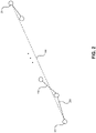
- FIG. 2 illustrates an exemplary trace of an object-on-hand, according to one example. Note that for simplicity of illustration, only the displacement, not the 3D pose, of the object-on-hand is shown.
- an object is to be moved, by the robotic arm, from a starting position 202 to an ending position 204.
- the distance between starting position 202 and ending position 204 is greater than a predetermined maximum displacement.
- the value of the maximum displacement can depend on the desired positioning accuracy. The higher the desired accuracy is, the lower the value of the maximum displacement is. In some examples, sub-millimeter positioning accuracy is required, and the maximum displacement value can be between 5 and 10 mm.
- FIG. 2 shows that, instead of moving the object in one step following a direct path 200, the robotic arm moves the object in a number of small steps, e.g., steps 206 and 208.
- the displacement of the object in each step can be equal to or less than the predetermined maximum displacement.
- the small step can ensure that the positioning amount resulting from errors in the transformation matrix can be kept small, and the actual path taken by the object may not diverge significantly from direct path 200. For illustration purposes, the path divergence is exaggerated in FIG. 2 .
- the way the robotic arm moves the object to a destination pose using a sequence of small steps and adjusting, at each step, the path based on visual feedback can be similar to the way a human performs a movement that requires accurate hand positioning (e.g., threading a needle).
- the robot Like a human who relies on the eyes to determine the current poses of the needle and thread in order to adjust the hand movement, the robot relies on its eyes (e.g., the 3D machine-vision system) to determine the actual pose of the object at each small step.
- the machine-vision system may need to determine the poses of the multiple objects in order to guide the robotic arm to move an object from one pose to the other.
- the 3D machine-vision system can include two vision modules, with each vision module including two cameras and a structured-light projector. One of the two vision modules can be mounted directly above the working space, whereas the other vision module can be mounted at an angle.
- Detailed descriptions of the 3D machine-vision system can be found in PCT Application No. PCT/US2020/043105 , entitled “SYSTEM AND METHOD FOR 3D POSE MEASUREMENT WITH HIGH PRECISION AND REAL-TIME OBJECT TRACING,” by inventors MingDu Kang, Kai C. Yung, Wing Tsui, and Zheng Xu, filed 22 July 2020, the disclosure of which is incorporated herein by reference in its entirety.
- the 3D machine-vision system can control all four cameras to capture one image of the working space and send the images to an instance-segmentation neural network to better understand the scene.
- the instant-segmentation neural network can generate both a semantic map (which classifies whether each pixel belongs to the background or an object) and an instance center for each object. Based on the semantic map and the instance centers, the 3D machine-vision system can identify what objects are in the scene and generate a mask for each object.
- the 3D machine-vision system can control the structured-light projectors to project patterns onto the objects and control the cameras to capture images of the objects under the illumination of the structured light.
- the captured images can be used to construct a 3D point cloud of the environment. More specifically, constructing the 3D point cloud can include generating a decode map based on the projected images of the structured-light projector, associating camera pixels with projector pixels, and triangulating 3D points, based on the camera-and-projector intrinsic matrix, the relative position between the cameras and projectors, and the camera-projector pixel associations.
- the 3D machine-vision system can isolate an object of interest and generate a 3D point cloud for that object.
- the 3D pose of an object in the FOV of the machine-vision system can be estimated or determined using a surflet-based template-matching technique.
- a surflet refers to an oriented point on the surface of a 3D object.
- Each surflet can be described as a pair ( p , n ), where p is the position vector and n is the surface normal.
- Surflet-pair relations can be viewed as a generalization of curvatures.
- the surflet-based template-matching technique is based on a known CAD model of the object.
- a number of surflet pairs can be extracted from the CAD model of the objects, and the extracted surflet pairs (as expressed using equation (10)) can be stored in a 4D hash map.
- the 3D machine-vision system can generate the 3D point cloud of an object and compute surflet pairs based on the 3D point cloud.
- the surflet pairs of the object are associated with the surflet pairs of the CAD models using the pre-computed hash map, and the 3D pose of the object can be estimated accordingly.
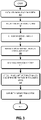
- FIG. 3 presents a flowchart illustrating an exemplary process for calibrating the robotic system and obtaining the transformation matrix, according to one example.
- the 3D machine-vision system is installed (operation 302).
- the 3D machine-vision system can include multiple cameras and a structured-light projector.
- the 3D machine-vision system can be mounted and secured above the end-effector of the robotic arm being calibrated, with the lenses of the cameras and the structured-light projector facing the end-effector of the robotic arm.
- the robot operator can mount and secure the 6-axis robotic arm, so that the robotic arm's end-effector can move freely to all possible poses within the FOV and depth of view (DOV) of the 3D machine-vision system (operation 304).
- DOV depth of view
- a calibration target (e.g., target 114 shown in FIG. 1 ) can be attached to the end-effector (operation 306).
- the predetermined pattern on the calibration target can facilitate the 3D machine-vision system in determining the pose (which includes not only the location but also the tilt angle) of the end-effector.
- the surface area of the calibration target is smaller than the FOV of the 3D machine-vision system.
- the controller of the robotic arm can generate a number of predetermined poses in the robot-base space (operation 308) and sequentially move the end-effector to those poses (operation 310).
- the 3D machine-vision system can capture images of the calibration target and determine the pose of the calibration target in the camera space (operation 312).
- the transformation matrix can then be derived based on poses generated in the robot-base space and the machine-vision-determined poses in the camera space (operation 314).
- Various techniques can be used to determine the transformation matrix.
- equation (4) can be solved based on the predetermined poses in the robot-base space and the camera space using various techniques, including but not limited to: linear least square or SVD techniques, Lie-theory-based techniques, techniques based on quaternion and non-linear minimization or dual quaternion, techniques based on Kronecker product and vectorization, etc.
- the robotic system can be used to complete assembly tasks, such as picking up a component in a working space, adjusting the pose of the component, and mounting the component at a mounting location.
- the robotic arm moves in small steps, and at each small step, the current pose of the end-effector or component is measured, using the 3D machine-vision system, and the next pose is computed based on the measured pose and the target pose.
- FIG. 4 presents a flowchart illustrating an exemplary operation process of the robotic system, according to one example.
- the robotic system can include the robotic arm and the 3D machine-vision system.
- an operator can install a gripper on the robotic arm and calibrate its TCP (operation 402).
- the robotic controller can move the gripper to the vicinity of a to-be-assembled component in the working space under the guidance of the 3D machine-vision system (operation 404).
- the 3D machine-vision system may generate low-resolution images (e.g., using a camera with a large FOV) to guide the movement of the gripper.
- the positioning accuracy of the gripper is less critical. For example, the gripper can be moved from its original location to the vicinity of the to-be-assembled component in one large step.
- the 3D machine-vision system can determine the pose of the component in the camera space (operation 406). Note that there can be multiple components within the working space, and determining the pose of the to-be-assembled component can involve the steps of identifying that component and generating a 3D point cloud for that component.
- FIG. 5 presents a flowchart illustrating an exemplary process for determining the pose of a component, according to one example.
- the 3D machine-vision system can capture one or more images of the working space (operation 502).
- the images can be inputted to an instance-segmentation machine-learning model (e.g., a deep-learning neural network), which outputs a semantic map for the scene and an instance center for the component (operation 504).
- a mask for the object can be generated based on the semantic map and the instance center (operation 506).
- the 3D machine-vision system can further capture images of the scene under the illumination of the structured light (operation 508) and generate a 3D point cloud for the component based on the captured images and the mask of the component (operation 510).
- generating the 3D point cloud may include the steps of generating a decode map based on images captured under the illumination of the structured light and triangulating each 3D point based on the intrinsic matrix of the camera and projector, the relative position between the camera and projection, and the camera-projector pixel association.
- the 3D machine-vision system can further compute surflet pairs from the 3D point cloud (operation 512) and compare the computed surflet pairs of the 3D point cloud with the surflet pairs of a 3D CAD model of the component (operation 514).
- the 3D pose of the component can then be estimated based on the comparison result (operation 516). Note that the estimated pose is in the camera space.
- the robotic system can then convert the component pose from the camera space to the robot-base space using the transformation matrix derived during calibration (operation 408).
- the TCP pose of the gripper should be aligned with the component to facilitate the gripper picking up the component.
- the converted component pose can be the target pose of the gripper TCP.
- the robotic controller can determine a small step for moving the gripper (operation 410). Determine the small step can include computing an intermediate pose to move the gripper toward the target pose.
- the intermediate pose may be on the direct path between the initial pose and target pose.
- the amount of displacement of the gripper in this small step can be equal to or smaller than a predetermined maximum displacement.
- the robotic controller can generate motion commands based on the determined small step and send the motion commands to the robotic arm (operation 412).
- the gripper moves accordingly to the intermediate pose (operation 414).
- the 3D machine-vision system estimates the pose of the gripper (operation 416) and determines if the gripper arrived at its target pose (operation 418). Note that a process similar to what is shown in FIG. 5 can be used to determine/estimate the pose of the gripper.
- the gripper can grasp the component (operation 420). Otherwise, the robotic controller can determine a next small step for moving the gripper (operation 410). Note that determining the next small step can include computing an intermediate pose of the component.
- the robotic controller can move the gripper with the component to the vicinity of a mounting location for the component under the guidance of the 3D machine-vision system (422).
- the 3D machine-vision system can operate at low resolution and the gripper with the component can be moved in a large step.
- the 3D machine-vision system can determine the pose of the mounting location in the camera space and convert such a pose to the robot-base space (operation 424). For example, if the grasped component is to mate with another component, the 3D machine-vision system can determine the pose of the other component. Based on the pose of the mounting location, the robotic system can determine the target mounting pose of the component held by the gripper (operation 426).
- the robotic controller can then move the component to its target mounting pose using a number of small-step movements (operation 428).
- the 3D machine-vision system can determine the actual pose of the component in the camera space and convert the pose to the robot-base space.
- the robotic controller can then determine a small step to be taken to move the component toward its target pose.
- the robotic controller can control the gripper to mount and secure the component (operation 430).
- the component is mounted to a stationary location.
- two to-be-assembled components are held by two robotic arms.
- the two robotic arms can each move their end-effectors in small steps while determining the poses of both components at each step, until the two components can be aligned for assembly.
- both robotic arms move, similar to the way both hands of a human move in order to align the end of the thread with the hole of the needle when threading the needle.
- a trained machine-learning model e.g., a neural network
- the error matrix can be used to corelate the camera-instructed pose of a component with a controller-desired pose.
- the system can compensate for the errors in the transformation matrix by having the robotic controller generate commands for the controller-desired pose.
- FIG. 6 shows a block diagram of an exemplary robotic system, according to one example.
- Robotic system 600 can include a 3D machine-vision module 602, a six-axis robotic arm 604, a robotic-control module 606, a coordinate-transformation module 608, an instance-segmentation machine-learning model 610, a point-cloud-generation module 612, a template-matching module 614, and a 3D-pose-estimation module 616.
- 3D machine-vision module 602 can use 3D machine-vision techniques (e.g., capturing images under structured-light illumination, constructing 3D point cloud, etc.) to determine the 3D pose of objects (including both to-be-assembled components and the gripper) within the FOV and DOV of the cameras.
- 3D machine-vision module 602 can include multiple cameras having different FOVs and DOVs and one or more structured-light projector.
- Six-axis robotic arm 604 can have multiple joints and 6DoF.
- the end-effector of six-axis robotic arm 604 can move freely in the FOV and DOV of the cameras of 3D machine-vision module 602.
- robotic arm 604 can include multiple sections, with adjacent sections coupled to each other via a rotational joint.
- Each rotational joint can include a servo motor capable of continuous rotation within a particular plane.
- the combination of the multiple rotational joints can enable robotic arm 604 to have an extensive range of movement with 6DoF.
- Robotic-control module 606 controls the movements of robotic arm 604.
- Robotic-control module 606 can generate a motion plan, which can include a sequence of motion commands that can be sent to each individual motor in robotic arm 604 to facilitate movements of a gripper to accomplish particular assembling tasks, such as picking up a component, moving the component to a desired mounting location, and mounting the component.
- robotic-control module 606 can be configured to confine each movement of the gripper to a small step, such that the displacement of each small step is equal to or less than a predetermined maximum displacement value.
- the maximum displacement value can be determined based on the desired level of positioning accuracy. A higher positioning accuracy means a smaller maximum displacement value for each small step.
- Coordinate-transformation module 608 can be responsible for converting the pose of the gripper or component from the camera space to the robot-base space. Coordinate-transformation module 608 can maintain a transformation matrix and use the transformation matrix to transform a pose seen by 3D machine-vision module 602 in the camera space to a pose in the robot-base space. The transformation matrix can be obtained through a calibration process that measures multiple poses of a calibration target.
- Instance-segmentation machine-learning model 610 applies a machine-learning technique to generate both a semantic map and instance centers for a captured image comprising multiple components.
- a mask for each object can be generated based on the output of instance-segmentation machine-learning model 610.
- Point-cloud-generation module 612 can be configured to generate a 3D point cloud for a to-be-assembled component.
- Template-matching module 614 can be configured to use a template-matching technique to compare surflet pairs of the 3D point cloud to surflet pairs of a 3D CAD model.
- 3D-pose-estimation module 616 can be configured to estimate the 3D pose of the to-be-assembled component based on the output of template-matching module 614.
- FIG. 7 illustrates an exemplary computer system that facilitates small-step movement in a robotic system, according to one example.
- Computer system 700 includes a processor 702, a memory 704, and a storage device 706. Furthermore, computer system 700 can be coupled to peripheral input/output (I/O) user devices 710, e.g., a display device 712, a keyboard 714, and a pointing device 716.
- I/O peripheral input/output
- Storage device 706 can store an operating system 720, a small-step-movement-control system 722, and data 740.
- Small-step-movement-control system 722 can include instructions, which when executed by computer system 700, can cause computer system 700 or processor 702 to perform methods and/or processes described in this disclosure.
- small-step-movement-control system 722 can include instructions for controlling a 3D machine-vision module to measure actual poses of the gripper (machine-vision-control module 724), instructions for controlling movements of the robotic arm in order to place the gripper in a particular pose (robotic-control module 726), instructions for transforming poses from the camera space to the robot-base space (coordinate-transformation module 728), instructions for executing an instance-segmentation machine-learning model to generate a mask for a to-be-assembled component in captured images of the working space (instance-segmentation-model-execution module 730), instructions for generating a 3D point cloud for the to-be-assembled component (point-cloud-generation module 732), instructions for applying a template-matching technique to compare surflet pairs of the 3D point cloud and a
- examples can provide a system and method for detecting and compensating, in real time, for pose errors of a robotic system.
- the system can use machine-learning techniques (e.g., training a neural network) to predict an error matrix that can transform a camera-viewed pose (i.e., the instructed pose) to a controller-controlled pose (i.e., the desired pose). Therefore, to align the gripper with a component in the camera view, the system can first obtain the camera-viewed pose of the component and then use the trained neural network to predict the error matrix. By multiplying the camera-viewed pose with the error matrix, the system can obtain the controller-controlled pose. The robotic controller can then use the controller-controlled pose to move the gripper to the desired pose.
- machine-learning techniques e.g., training a neural network
- the methods and processes described in the detailed description section can be embodied as code and/or data, which can be stored in a computer-readable storage medium as described above.
- a computer system reads and executes the code and/or data stored on the computer-readable storage medium, the computer system performs the methods and processes embodied as data structures and code and stored within the computer-readable storage medium.
- the methods and processes described above can be included in hardware modules or apparatus.
- the hardware modules or apparatus can include, but are not limited to, application-specific integrated circuit (ASIC) chips, field-programmable gate arrays (FPGAs), dedicated or shared processors that execute a particular software module or a piece of code at a particular time, and other programmable-logic devices now known or later developed.
- ASIC application-specific integrated circuit
- FPGA field-programmable gate arrays
- dedicated or shared processors that execute a particular software module or a piece of code at a particular time
- other programmable-logic devices now known or later developed.
Landscapes
- Engineering & Computer Science (AREA)
- Robotics (AREA)
- Mechanical Engineering (AREA)
- Physics & Mathematics (AREA)
- Theoretical Computer Science (AREA)
- Software Systems (AREA)
- Mathematical Physics (AREA)
- Computer Vision & Pattern Recognition (AREA)
- General Physics & Mathematics (AREA)
- Artificial Intelligence (AREA)
- Evolutionary Computation (AREA)
- Automation & Control Theory (AREA)
- Data Mining & Analysis (AREA)
- General Engineering & Computer Science (AREA)
- Computing Systems (AREA)
- Medical Informatics (AREA)
- Fuzzy Systems (AREA)
- Manipulator (AREA)
Applications Claiming Priority (4)
| Application Number | Priority Date | Filing Date | Title |
|---|---|---|---|
| US202163208816P | 2021-06-09 | 2021-06-09 | |
| US202163209933P | 2021-06-11 | 2021-06-11 | |
| US17/751,228 US12030184B2 (en) | 2021-06-09 | 2022-05-23 | System and method for error correction and compensation for 3D eye-to-hand coordination |
| US17/751,348 US12194643B2 (en) | 2021-06-09 | 2022-05-23 | System and method for improving accuracy of 3D eye-to-hand coordination of a robotic system |
Publications (1)
| Publication Number | Publication Date |
|---|---|
| EP4101604A1 true EP4101604A1 (de) | 2022-12-14 |
Family
ID=81854328
Family Applications (2)
| Application Number | Title | Priority Date | Filing Date |
|---|---|---|---|
| EP22176284.2A Withdrawn EP4116043A3 (de) | 2021-06-09 | 2022-05-31 | System und verfahren zur fehlerkorrektur und -kompensation für die 3d-augen-hand-koordination |
| EP22176286.7A Withdrawn EP4101604A1 (de) | 2021-06-09 | 2022-05-31 | System und verfahren zur verbesserung der genauigkeit der 3d-augen-hand-koordination eines robotersystems |
Family Applications Before (1)
| Application Number | Title | Priority Date | Filing Date |
|---|---|---|---|
| EP22176284.2A Withdrawn EP4116043A3 (de) | 2021-06-09 | 2022-05-31 | System und verfahren zur fehlerkorrektur und -kompensation für die 3d-augen-hand-koordination |
Country Status (2)
| Country | Link |
|---|---|
| EP (2) | EP4116043A3 (de) |
| CN (2) | CN115446847B (de) |
Cited By (5)
| Publication number | Priority date | Publication date | Assignee | Title |
|---|---|---|---|---|
| US20220335295A1 (en) * | 2021-04-14 | 2022-10-20 | Robert Bosch Gmbh | Device and method for training a neural network for controlling a robot for an inserting task |
| CN115990890A (zh) * | 2023-03-23 | 2023-04-21 | 深圳广成创新技术有限公司 | 一种机械手的标定方法、装置、计算机设备和存储介质 |
| CN116551690A (zh) * | 2023-05-24 | 2023-08-08 | 广州民航职业技术学院 | 一种柔性驱动关节的力矩控制方法和系统 |
| US20240269845A1 (en) * | 2021-05-28 | 2024-08-15 | Kyocera Corporation | Hold position determination device and hold position determination method |
| CN119795164A (zh) * | 2024-12-27 | 2025-04-11 | 青岛科捷高新装备制造有限公司 | 相机移动检测与抓取坐标补偿方法 |
Families Citing this family (5)
| Publication number | Priority date | Publication date | Assignee | Title |
|---|---|---|---|---|
| US12030184B2 (en) * | 2021-06-09 | 2024-07-09 | eBots Inc. | System and method for error correction and compensation for 3D eye-to-hand coordination |
| EP4116043A3 (de) * | 2021-06-09 | 2023-02-15 | Ebots, Inc. | System und verfahren zur fehlerkorrektur und -kompensation für die 3d-augen-hand-koordination |
| CN117565040A (zh) * | 2023-11-23 | 2024-02-20 | 泉州通维科技有限责任公司 | 一种基于视觉引导定位的配电柜巡操装置及方法 |
| CN119897872B (zh) * | 2025-03-31 | 2025-08-05 | 浙江强脑科技有限公司 | 机械臂的手眼标定方法、装置、设备及存储介质 |
| CN121374654B (zh) * | 2025-12-25 | 2026-03-24 | 山东大学 | 一种机械臂线缆装配方法及系统 |
Citations (3)
| Publication number | Priority date | Publication date | Assignee | Title |
|---|---|---|---|---|
| US20110280472A1 (en) * | 2010-05-14 | 2011-11-17 | Wallack Aaron S | System and method for robust calibration between a machine vision system and a robot |
| US20200238525A1 (en) * | 2019-01-28 | 2020-07-30 | Cognex Corporation | System and method for automatic hand-eye calibration of vision system for robot motion |
| CN110555889B (zh) * | 2019-08-27 | 2021-01-15 | 西安交通大学 | 一种基于CALTag和点云信息的深度相机手眼标定方法 |
Family Cites Families (13)
| Publication number | Priority date | Publication date | Assignee | Title |
|---|---|---|---|---|
| EP0589394A1 (de) * | 1992-09-21 | 1994-03-30 | Toyoda Koki Kabushiki Kaisha | Verfahren und Gerät zur Steuerung eines Roboters mit einem neuronalen Netzwerk |
| US9188973B2 (en) * | 2011-07-08 | 2015-11-17 | Restoration Robotics, Inc. | Calibration and transformation of a camera system's coordinate system |
| JP5897624B2 (ja) * | 2014-03-12 | 2016-03-30 | ファナック株式会社 | ワークの取出工程をシミュレーションするロボットシミュレーション装置 |
| CN109304710A (zh) * | 2017-07-27 | 2019-02-05 | 中国商用飞机有限责任公司 | 基于径向基神经网络的机械臂精度标定方法 |
| US11117262B2 (en) * | 2017-08-01 | 2021-09-14 | eBots Inc. | Intelligent robots |
| CN108818535B (zh) * | 2018-07-05 | 2020-04-10 | 苏州汉振深目智能科技有限公司 | 机器人3d视觉手眼标定方法 |
| TWI672206B (zh) * | 2018-12-19 | 2019-09-21 | 財團法人工業技術研究院 | 機械手臂非接觸式工具中心點校正裝置及其方法以及具有校正功能的機械手臂系統 |
| CN109864806A (zh) * | 2018-12-19 | 2019-06-11 | 江苏集萃智能制造技术研究所有限公司 | 基于双目视觉的动态补偿功能的穿刺机器人导航系统 |
| CN110253574B (zh) * | 2019-06-05 | 2020-11-17 | 浙江大学 | 一种多任务机械臂位姿检测和误差补偿方法 |
| CN110450163A (zh) * | 2019-08-20 | 2019-11-15 | 上海中车瑞伯德智能系统股份有限公司 | 无需标定板的基于3d视觉的通用手眼标定方法 |
| EP4017688B1 (de) * | 2019-09-30 | 2025-08-20 | Siemens Aktiengesellschaft | Maschinenlernfähiges visuelles servoing mit dedizierter hardwarebeschleunigung |
| CN112518753B (zh) * | 2020-12-04 | 2022-02-01 | 浙江理工大学 | 一种神经网络迭代补偿的工业机器人轨迹跟踪系统和方法 |
| EP4116043A3 (de) * | 2021-06-09 | 2023-02-15 | Ebots, Inc. | System und verfahren zur fehlerkorrektur und -kompensation für die 3d-augen-hand-koordination |
-
2022
- 2022-05-31 EP EP22176284.2A patent/EP4116043A3/de not_active Withdrawn
- 2022-05-31 EP EP22176286.7A patent/EP4101604A1/de not_active Withdrawn
- 2022-06-07 CN CN202210637151.2A patent/CN115446847B/zh active Active
- 2022-06-07 CN CN202210638283.7A patent/CN115519536A/zh active Pending
Patent Citations (3)
| Publication number | Priority date | Publication date | Assignee | Title |
|---|---|---|---|---|
| US20110280472A1 (en) * | 2010-05-14 | 2011-11-17 | Wallack Aaron S | System and method for robust calibration between a machine vision system and a robot |
| US20200238525A1 (en) * | 2019-01-28 | 2020-07-30 | Cognex Corporation | System and method for automatic hand-eye calibration of vision system for robot motion |
| CN110555889B (zh) * | 2019-08-27 | 2021-01-15 | 西安交通大学 | 一种基于CALTag和点云信息的深度相机手眼标定方法 |
Non-Patent Citations (2)
| Title |
|---|
| "Robotics : modelling, planning and control", 31 December 2009, SPRINGER, UK, ISBN: 978-1-84628-641-4, article BRUNO SICILIANO ET AL: "Visual Servoing", pages: 407 - 467, XP055460541, DOI: 10.1007/978-1-84628-642-1 * |
| XIAN-FENG HAN ET AL: "3D Point Cloud Descriptors in Hand-crafted and Deep Learning Age: State-of-the-Art", ARXIV.ORG, CORNELL UNIVERSITY LIBRARY, 201 OLIN LIBRARY CORNELL UNIVERSITY ITHACA, NY 14853, 27 July 2020 (2020-07-27), XP081701927 * |
Cited By (6)
| Publication number | Priority date | Publication date | Assignee | Title |
|---|---|---|---|---|
| US20220335295A1 (en) * | 2021-04-14 | 2022-10-20 | Robert Bosch Gmbh | Device and method for training a neural network for controlling a robot for an inserting task |
| US12456050B2 (en) * | 2021-04-14 | 2025-10-28 | Robert Bosch Gmbh | Device and method for training a neural network for controlling a robot for an inserting task |
| US20240269845A1 (en) * | 2021-05-28 | 2024-08-15 | Kyocera Corporation | Hold position determination device and hold position determination method |
| CN115990890A (zh) * | 2023-03-23 | 2023-04-21 | 深圳广成创新技术有限公司 | 一种机械手的标定方法、装置、计算机设备和存储介质 |
| CN116551690A (zh) * | 2023-05-24 | 2023-08-08 | 广州民航职业技术学院 | 一种柔性驱动关节的力矩控制方法和系统 |
| CN119795164A (zh) * | 2024-12-27 | 2025-04-11 | 青岛科捷高新装备制造有限公司 | 相机移动检测与抓取坐标补偿方法 |
Also Published As
| Publication number | Publication date |
|---|---|
| CN115446847B (zh) | 2025-10-17 |
| EP4116043A3 (de) | 2023-02-15 |
| CN115446847A (zh) | 2022-12-09 |
| EP4116043A2 (de) | 2023-01-11 |
| CN115519536A (zh) | 2022-12-27 |
Similar Documents
| Publication | Publication Date | Title |
|---|---|---|
| EP4101604A1 (de) | System und verfahren zur verbesserung der genauigkeit der 3d-augen-hand-koordination eines robotersystems | |
| US12194643B2 (en) | System and method for improving accuracy of 3D eye-to-hand coordination of a robotic system | |
| US12030184B2 (en) | System and method for error correction and compensation for 3D eye-to-hand coordination | |
| JP6966582B2 (ja) | ロボットモーション用のビジョンシステムの自動ハンドアイ校正のためのシステム及び方法 | |
| JP6429473B2 (ja) | ロボットシステム、ロボットシステムの校正方法、プログラム、およびコンピュータ読み取り可能な記録媒体 | |
| JP6108860B2 (ja) | ロボットシステム及びロボットシステムの制御方法 | |
| CN111801198B (zh) | 一种手眼标定方法、系统及计算机存储介质 | |
| US9457470B2 (en) | Robot system and method for calibration | |
| US9519736B2 (en) | Data generation device for vision sensor and detection simulation system | |
| US20190184570A1 (en) | Intelligent robots | |
| US11285609B2 (en) | Working position correcting method and working robot | |
| US20110071675A1 (en) | Visual perception system and method for a humanoid robot | |
| JP6912529B2 (ja) | 視覚誘導ロボットアームの補正方法 | |
| US12128571B2 (en) | 3D computer-vision system with variable spatial resolution | |
| JP2023108062A (ja) | 制御装置、ロボット装置、制御方法、およびプログラム | |
| KR20130075712A (ko) | 레이저비전 센서 및 그 보정방법 | |
| EP4713170A1 (de) | Verfahren und systeme zum kompensieren einer abweichung in einer mehrzahl von arbeitsposen eines manipulators einer autonomen ladevorrichtung | |
| US12515334B2 (en) | Task teaching method and task teaching system | |
| JP7660686B2 (ja) | ロボット制御装置、ロボット制御システム、及びロボット制御方法 | |
| Park et al. | Robot-based Object Pose Auto-annotation System for Dexterous Manipulation | |
| CN117140532B (zh) | 一种工业机器人三维视觉工作站坐标系标定及操作方法 | |
| CN119283020A (zh) | 一种用于机器人末端准确夹取的“眼在手上”快速手眼标定方法 | |
| Liu et al. | Development and experiment of CSM-based industrial robot servoing control system |
Legal Events
| Date | Code | Title | Description |
|---|---|---|---|
| PUAI | Public reference made under article 153(3) epc to a published international application that has entered the european phase |
Free format text: ORIGINAL CODE: 0009012 |
|
| STAA | Information on the status of an ep patent application or granted ep patent |
Free format text: STATUS: THE APPLICATION HAS BEEN PUBLISHED |
|
| AK | Designated contracting states |
Kind code of ref document: A1 Designated state(s): AL AT BE BG CH CY CZ DE DK EE ES FI FR GB GR HR HU IE IS IT LI LT LU LV MC MK MT NL NO PL PT RO RS SE SI SK SM TR |
|
| STAA | Information on the status of an ep patent application or granted ep patent |
Free format text: STATUS: REQUEST FOR EXAMINATION WAS MADE |
|
| 17P | Request for examination filed |
Effective date: 20230206 |
|
| RBV | Designated contracting states (corrected) |
Designated state(s): AL AT BE BG CH CY CZ DE DK EE ES FI FR GB GR HR HU IE IS IT LI LT LU LV MC MK MT NL NO PL PT RO RS SE SI SK SM TR |
|
| STAA | Information on the status of an ep patent application or granted ep patent |
Free format text: STATUS: THE APPLICATION IS DEEMED TO BE WITHDRAWN |
|
| 18D | Application deemed to be withdrawn |
Effective date: 20241203 |