EP4101606B1 - Taktiler sensor - Google Patents
Taktiler sensor Download PDFInfo
- Publication number
- EP4101606B1 EP4101606B1 EP21834225.1A EP21834225A EP4101606B1 EP 4101606 B1 EP4101606 B1 EP 4101606B1 EP 21834225 A EP21834225 A EP 21834225A EP 4101606 B1 EP4101606 B1 EP 4101606B1
- Authority
- EP
- European Patent Office
- Prior art keywords
- sensing
- detection
- tactile sensor
- electrode
- contact
- Prior art date
- Legal status (The legal status is an assumption and is not a legal conclusion. Google has not performed a legal analysis and makes no representation as to the accuracy of the status listed.)
- Active
Links
Images

Classifications
-
- B—PERFORMING OPERATIONS; TRANSPORTING
- B25—HAND TOOLS; PORTABLE POWER-DRIVEN TOOLS; MANIPULATORS
- B25J—MANIPULATORS; CHAMBERS PROVIDED WITH MANIPULATION DEVICES
- B25J19/00—Accessories fitted to manipulators, e.g. for monitoring, for viewing; Safety devices combined with or specially adapted for use in connection with manipulators
- B25J19/02—Sensing devices
- B25J19/028—Piezoresistive or piezoelectric sensing devices
-
- B—PERFORMING OPERATIONS; TRANSPORTING
- B25—HAND TOOLS; PORTABLE POWER-DRIVEN TOOLS; MANIPULATORS
- B25J—MANIPULATORS; CHAMBERS PROVIDED WITH MANIPULATION DEVICES
- B25J13/00—Controls for manipulators
- B25J13/08—Controls for manipulators by means of sensing devices, e.g. viewing or touching devices
- B25J13/081—Touching devices, e.g. pressure-sensitive
- B25J13/082—Grasping-force detectors
-
- B—PERFORMING OPERATIONS; TRANSPORTING
- B25—HAND TOOLS; PORTABLE POWER-DRIVEN TOOLS; MANIPULATORS
- B25J—MANIPULATORS; CHAMBERS PROVIDED WITH MANIPULATION DEVICES
- B25J13/00—Controls for manipulators
- B25J13/08—Controls for manipulators by means of sensing devices, e.g. viewing or touching devices
- B25J13/081—Touching devices, e.g. pressure-sensitive
- B25J13/084—Tactile sensors
-
- G—PHYSICS
- G01—MEASURING; TESTING
- G01L—MEASURING FORCE, STRESS, TORQUE, WORK, MECHANICAL POWER, MECHANICAL EFFICIENCY, OR FLUID PRESSURE
- G01L5/00—Apparatus for, or methods of, measuring force, work, mechanical power, or torque, specially adapted for specific purposes
- G01L5/22—Apparatus for, or methods of, measuring force, work, mechanical power, or torque, specially adapted for specific purposes for measuring the force applied to control members, e.g. control members of vehicles, triggers
- G01L5/226—Apparatus for, or methods of, measuring force, work, mechanical power, or torque, specially adapted for specific purposes for measuring the force applied to control members, e.g. control members of vehicles, triggers to manipulators, e.g. the force due to gripping
- G01L5/228—Apparatus for, or methods of, measuring force, work, mechanical power, or torque, specially adapted for specific purposes for measuring the force applied to control members, e.g. control members of vehicles, triggers to manipulators, e.g. the force due to gripping using tactile array force sensors
Definitions
- the present invention relates to the technical field of sensors, specifically to a tactile sensor applied to a manipulator.
- a manipulator is an automatic operation device that can imitate certain action functions of human hands and arms, and grabs and transports objects or operates tools according to fixed procedures.
- the manipulator can replace the heavy labor of people to achieve mechanization and automation of production.
- the manipulator can also be operated in harmful environments to protect personal safety, so the manipulator is widely used in machine manufacturing, metallurgy, electronics, light industry and atomic energy departments and other departments.
- the manipulator needs to sense a contact point between the manipulator and an object to be grabbed as well as a magnitude of a grabbing force (i.e., the tactile sense and the force sense) at the contact point.
- the pressure sensor has no tactile sense and force sense feedbacks, so the flexibility is greatly affected, resulting in a significant decrease in the grabbing accuracy of objects, often causing the grabbing action to be tilted and making the objects drop.
- the current pressure sensor usually uses a single-point pressure sensor.
- sensor arrays are used in joints of the manipulator. Parameters of contact points are measured by an arraying method.
- arrayed pressure sensors are used, due to a very small space in the manipulator and the limited number of pressure sensors in the array, positions of contact points cannot be accurately sensed, which cannot meet the requirements of the manipulator for grabbing fine objects.
- An embodiment of the present invention provides a tactile sensor to at least solve the following technical problem in the related art: a manipulator adopting a pressure sensor cannot accurately sense contact points of the manipulator and an object, resulting in a significant decrease in accuracy of grabbing an object.
- the invention is defined by the appended claims.
- a tactile sensor which is applied to a manipulator and includes: a contact part, configured to receive pressure transmitted when a manipulator grabs a target object, and transmit the pressure to a sensing part; the sensing part being located on one side of the contact part, moving in a direction away from the contact part under an action of the pressure and comprising a sensing electrode; and a detection part, located on a side of the sensing part away from the contact part, the detection part sensing a position change of the sensing part to generate a sensing signal, wherein the sensing signal is configured to determine a contact parameter between the manipulator and the target object.
- the detection part includes: a detection base plate; and a sensor chip, located on the detection base plate; the sensing electrode has a projection on the sensor chip; an d the sensor chip is electrically connected to the detection base platw through a bonding wire.
- the tactile sensor further includes: an elastic part, located on one side of the contact part, and the sensing part is located between the contact part and the elastic part.
- the detection base plate includes: an electrical interface, connected to external equipment and configured to provide an electrical control signal to the detection base plate and transmit the sensing signal to outside.
- the sensor chip includes: a plurality of detection electrodes, configured to form an electric field together with the sensing electrode, wherein each detection electrode has the same arrangement direction as that of the sensing electrode.
- the sensor chip further includes: an electrical connection electrode, configured to provide a working voltage and a driving signal to the sensor chip, wherein the driving signal includes at least one of the following: a clock signal CLK, a row driving signal SI and an output signal SIG.
- an electrical connection electrode configured to provide a working voltage and a driving signal to the sensor chip, wherein the driving signal includes at least one of the following: a clock signal CLK, a row driving signal SI and an output signal SIG.
- the detection part further includes: a frame body, configured to be provided with an accommodating cavity and an opening, the detection base plate and the sensor chip being located inside the accommodating cavity; and a protection structure, configured to be enclosed with the frame body to form a sealed space.
- the protection structure is one of a protection cover plate and an encapsulation adhesive.
- the contact part is made of a flexible material
- the elastic part is made of a rubber material.
- the contact part receives pressure transmitted when the manipulator grabs a target object, and transmits the pressure to a sensing part; the sensing part moves in the direction away from the contact part under the action of the pressure; and the detection part senses a position change of the foregoing sensing part to generate the sensing signal.
- the sensing signal is used for determining the contact parameter between the manipulator and the target object.
- the tactile sensor is capable of accurately detecting contact points between an object and a manipulator and the tactile sensor outputs and feeds back sensed pressure to the outside in the form of a sensing signal, thus continuously monitoring a grabbing state of the manipulator; the contact points when the manipulator grabs an object are adjusted to improve the accuracy of grabbing an object, so that the following technical problem in the related art is solved: the manipulator adopting a pressure sensor cannot accurately sense contact points of the manipulator and an object, resulting in a significant decrease in the accuracy of grabbing the object.
- a new tactile sensor is provided on a manipulator. Different tactile pressures act on a contact part and an elastic part, so that a sensing electrode in a sensing part generates different displacements; at the same time, different numbers of charges are generated on a detection electrode, thus outputting different sensing signals; and a manipulator of a contact force and positions of contact points can be calculated according to a magnitude of an output signal and an output waveform of the signal.
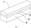
- FIG. 1 is a schematic diagram of an appearance of an optional tactile sensor according to an embodiment of the present invention.
- the tactile sensor is applied to a manipulator.
- the tactile sensor includes a contact part 1, a sensing part 2 and a detection part 4.
- the contact part 1 receives pressure transmitted when the manipulator grabs a target object, and transmits the pressure to the sensing part.
- the above-mentioned contact part 1 may be in contact with an external object to be grabbed, receives an external contact pressure, and transmits the pressure to the sensing part 2 and the elastic part 3.
- the sensing part 2 is located on one side of the contact part.
- the sensing part moves along a direction away from the contact part under an action of the pressure.
- the sensing part includes: a sensing electrode.
- the sensing electrode may be configured as a flat sheet-like electrode, which is configured to generate a corresponding deformation according to a magnitude of acting force when the target object is in contact with the manipulator.
- the tactile sensor further includes: an elastic part 3, which is located on one side of the contact part, and the sensing part is located between the contact part and the elastic part.
- the contact part may be made of a flexible material
- the elastic part may be made of a rubber material
- the elastic part 3 receives the external pressure transmitted by the contact part 1 to drive the sensing electrode to generate a corresponding deformation, so that a distance D between the sensing electrode and the detection part 4 changes with the external force.
- the above-mentioned sensing electrode may carry basic voltage to form an electric field together with a detection electrode (which is arranged in the detection part), and charges are formed on the detection electrode.
- the sensing electrode is located between the contact part 1 and the elastic part 3, and may generate a corresponding deformation with the deformation of the contact part 1 and the elastic part 3.
- the acting force of the contact with the target object is transmitted to the inside through the contact part 1, so that the sensing electrode and the elastic part 3 generate corresponding deformations with the acting force.
- the distance D between the sensing electrode and a surface of the detection part 4 will change.
- the sensing electrode 2 deforms more greatly, the value of D becomes smaller, and the sensing electrode is closer to the detection part 4.
- Different positions of the contact points indicate different positions where D changes. Therefore, the magnitude of the pressure and the position of an acting point can be measured, that is, the positions of the contact points and the magnitude of the contact force are determined.
- the basic voltage carried by the sensing electrode may be pre-applied.
- the basic voltage can be supplied by the detection part 4 or can be directly supplied as required.
- a voltage value of the basic voltage is one of key parameters of the entire tactile sensor.
- the voltage value is related to the flexibilities and thicknesses of the contact part 1 and the elastic part 3, and is also related to the initial distance D between the sensing electrode and the detection part 4. That is, the voltage value is related to a use environment of the tactile sensor, i.e., an upper limit design value of an initial weight of the target object. If the weight of an object to be grabbed is large, the contact part 1 and the elastic part 3 need to have low flexibility and large thickness, and the distance between the sensing electrode and the detection part 4 is long. At this time, a voltage applied to the detection electrode 2 is high. On the contrary, the voltage applied is low.
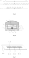
- FIG. 2 is a schematic diagram of a sectional structure of an optional tactile sensor according to an embodiment of the present invention.
- the tactile sensor includes a contact part 1, a sensing part 2 (which can be understood as a sensing electrode), a detection part 3 and a detection part 4.
- the detection part 4 is located on one side of the sensing part away from the contact part.
- the detection part generates a sensing signal by means of sensing a change in a position of the foregoing sensing part.
- the sensing signal is configured to determine a contact parameter between the manipulator and a target object.
- the detection part 4 includes: a detection base plate; and a sensor chip, which is located on the detection base plate; the sensing electrode has a projection on the sensor chip; and the sensor chip is electrically connected to the detection base plate through a bonding wire.
- the detection part 4 includes: a detection base 41, a sensor chip 42 and a bonding wire 43.
- the detection base plate includes: an electrical interface, connected to external equipment and is configured to provide an electrical control signal to the detection base plate and transmit the sensing signal to outside.
- the electrical interface is 44.
- the sensor chip 42 is carried on the detection base plate 41. Detection electrodes 421 are arranged on the sensor chip 42. The detection electrodes 421 are linearly arranged on a surface of the chip.
- the sensor chip may be a charge sensing sensor chip.
- the sensor chip on the detection part 4 includes: the detection electrodes 421 and electrical connection electrodes 422.
- FIG. 3 is a schematic diagram of an optional detection base plate according to an embodiment of the present invention.
- the detection base plate is provided with a sensor chip, and the sensor chip includes detection electrodes 421 and electrical connection electrodes 422.
- the sensor chip 42 is electrically connected to the detection base plate 41 through bonding wires 43.
- the detection base plate 41 is also provided with an electrical interface 44 for external connection.
- An electrical control signal is provided for the detection base plate 41 through the electrical interface 44, and a detected sensing signal is output to the outside.
- FIG. 4 is a schematic diagram of an optional detection base plate according to an embodiment of the present invention. As shown in FIG. 4 , the sensor chip 42 is provided with a plurality of detection electrodes 421 and electrical connection electrodes 422 which are arranged in parallel.
- the detection electrodes 421 form an electric field together with sensing electrodes. Each detection electrode has the same arrangement direction as the sensing electrode.
- the sensing electrodes and the detection electrodes 421 are arranged along the same direction, and the sensing electrodes may be arranged right above the detection electrodes 421.
- a voltage applied to the sensing electrodes and the detection electrodes 421 form an electric field, and sensing charges are generated on the detection electrodes 421.
- the sensor chip 42 can convert a charge signal generated on the detection electrodes 421 into a voltage signal to obtain a sensing signal, and the sensing signal is output to the outside.
- the detection electrode 421 is a planar metal electrode manufactured by a semiconductor process. Materials used in the manufacturing include an aluminum material.
- the detection electrode 421 is connected to a shift circuit inside an integrated circuit (IC) through a conventional logic switch, and is converted into a series signal output to the outside.
- the electrical connection electrodes 422 provide a working voltage and a driving signal to the sensor chip.
- the driving signal includes at least one of the following: a clock signal CLK, a row driving signal SI and an output signal SIG.
- the driving signal is not limited to the foregoing clock signal CLK and the row driving signal SI.
- FIG. 5 is a schematic diagram of an output signal of an optional electrical connection electrode according to an embodiment of the present invention.
- the sensor chip Under the driving of the clock signal, the sensor chip will carry out row scanning once every row driving signal SI (positive pulse) is output, and outputs a row of voltage signals corresponding to each detection electrode 421.
- SI positive pulse
- the tactile sensor can output the sensing signals to the outside in real time.
- a control system/control console After receiving the sensing signals, a control system/control console converts the sensing signals into pressure and position signals, so as to continuously monitor a working state of the manipulator.
- the sensor chip 42 arranged on the detection base plate 41 in FIG. 4 can be selected randomly.
- the sensor chip is a chip (unencapsulated bare chip) manufactured by a Complementary Metal-Oxide-Semiconductor Transistor (CMOS) process.
- CMOS Complementary Metal-Oxide-Semiconductor Transistor
- the detection electrodes 421 and the electrical connection electrodes 422 are arranged on a surface of the chip.
- the detection electrodes 421 are uniformly arranged along a lengthwise direction of the chip, and a size of each detection electrode 421 may be set according to a required resolution.
- the detection part further includes: a frame body, configured to be provided with an accommodating cavity and an opening, the detection base plate and the sensor chip being located inside the accommodating cavity; and a protection structure, configured to be enclosed with the frame body to form a sealed space.
- the protection structure is one of a protection cover plate and an encapsulation adhesive.
- the protection cover plate is 45
- the frame body is 46.
- the detection base plate 41 is mounted inside the frame body 46
- the protection cover plate 45 may be mounted on an upper surface of the frame body 46 and is configured to protect the sensor chip 42.
- D between the sensing part 2 and the protection cover plate 45 indicates a distance between the sensing electrode and a surface of the detection part.
- the contact part 1 is configured to receive pressure transmitted when the manipulator grabs the target object, and transmits the pressure to the sensing part; the sensing part 2 moves in the direction away from the contact part under the action of the pressure; and the detection part 4 senses a position change of the foregoing sensing part 2 to generate the sensing signal.
- the sensing signal is used for determining the contact parameter between the manipulator and the target object.
- a tactile sensor capable of accurately detecting contact points of an object and a manipulator is provided, which outputs and feeds back sensed pressure to the outside in the form of a sensing signal, thus continuously monitoring a grabbing state of the manipulator; the contact points when the manipulator grabs an object are adjusted to improve the accuracy of grabbing an object, so that the following technical problem in the related art is solved: the manipulator adopting a pressure sensor cannot accurately sense contact points of the manipulator and an object, resulting in a significant decrease in the accuracy of grabbing the object.
- the sensor chip 42 in a continuous working state will output signals to the outside in real time (even if the sensor chip is in no contact with an external object). Therefore, sensed pressure can be output and fed back to the outside in the form of a voltage signal, and the control system can continuously monitor the grabbing state of the manipulator.
- the direction of the sensing electrodes may be set to be the same as the arrangement direction of the detection electrodes 421; furthermore, the sensing electrodes are arranged right above the detection electrodes 421; and a plane where the sensing electrodes are located is parallel to a plane where the detection electrodes 421 are located.
- the quantity of charges sensed on the detection electrodes 421 are mainly determined by the basic voltage V applied to the sensing electrodes and the distance D between the sensing electrodes and the detection electrodes 421.
- the quantity of charges is in direct proportion to the basic voltage applied. A higher basic voltage V indicates more sensed charges.
- the quantity of charges is in inversely proportional to the distance D. A shorter distance D indicates more sensed charges.
- the embodiment of the present invention mainly aims to grab a lighter object.
- the elastic part 3 and the contact part 1 are relatively thin.
- the elastic part has a thickness of 2 mm and is made of a rubber material.
- the contact part 1 has a thickness of 5 mm and is also made of a rubber material.
- a copper foil that has a thickness of 0.03 mm and a width of 2 mm is used as the sensing electrode. The copper foil is fixedly adhered between the contact part 1 and the elastic part 2.
- the intensity of the sensing signal output by the tactile sensor is converted into the magnitude of contact force, and a position of an acting point can be obtained according to an output value of each detection electrode indicated by an output waveform.
- the contact part 1 and the elastic part 3 may be thickened, and their flexibilities may be reduced.
- the distance between the sensing electrodes and the detection part 4 will be prolonged, so that the tactile sensor can bear higher acting force.
- charges sensed on the detection electrodes 421 will decrease, and the sensitivity to the acting force will decrease.
- the intensity of the output signal can be improved by increasing the voltage on the sensing electrodes.
- FIG. 6 is a schematic diagram of another optional tactile sensor according to an embodiment of the present invention.
- an encapsulation layer 451 is used to protect the sensor chip, which replaces the protection cover plate mounted at the upper part of the chip.
- the encapsulation layer 451 can be formed by smearing an encapsulation adhesive.
- the elastic part 3 is only arranged around the surface of the detection part 4.
- An area for the sensing electrodes and the surface of the detection part is empty (it can also be considered that air is used as a medium). In this way, the position change range of the sensing electrodes can be enlarged, and the measurement range of the pressure can be enlarged.
- the tactile sensor can be made to be longer by arranging a plurality of sensor chips 42 on the detection base plate 41, so that the detection range can be enlarged.
- FIG. 7 is a schematic diagram of another sensor chip according to an embodiment of the present invention. As shown in FIG. 7 , three sensor chips 42 are arranged on the detection base plate 41, and an electrical interface 44 is also arranged on the detection base plate 41. At this time, the number of the detection electrodes 421 is 108, and the detection range can reach 54.9 mm.
- a plurality of tactile sensors can be arranged.
- the tactile sensor shown in FIG. 1 is mounted on a grabbing claw of a mechanical arm at intervals to form a sensing structure for a plurality of contact points.
- the solution provided by the embodiment of the present application can be used for continuously monitoring a grabbing state of a manipulator, adjusting contact points when the manipulator grabs an object, and improving the accuracy of grabbing an object.
- the technical solution provided by the embodiment of the present application can be applied to various manipulators.
- a new tactile sensor is provided on the manipulator. Different tactile pressures are used to act on a contact part and an elastic part to enable sensing electrodes in a sensing part to generate different displacements, and different quantities of charges are generated on detection electrodes, thus outputting different sensing signals.
- the magnitude of contact force and positions of contact points can be calculated according to the magnitudes of the output signals and output waveforms of the signals, so that the following technical problem in the related art is solved:
- a manipulator adopting a pressure sensor cannot accurately sense contact points of the manipulator and an object, resulting in a significant decrease in accuracy of grabbing an object.
- the embodiment of the present application can output and feed back sensed pressure to the outside in the form of a sensing signal, thus continuously monitoring a grabbing state of the manipulator; the contact points when the manipulator grabs an object are adjusted to improve the accuracy of grabbing an object.
Landscapes
- Engineering & Computer Science (AREA)
- Robotics (AREA)
- Mechanical Engineering (AREA)
- Human Computer Interaction (AREA)
- Chemical & Material Sciences (AREA)
- Analytical Chemistry (AREA)
- Physics & Mathematics (AREA)
- General Physics & Mathematics (AREA)
- Force Measurement Appropriate To Specific Purposes (AREA)
- Manipulator (AREA)
Claims (13)
- Taktiler Sensor, angewandt auf einen Manipulator, umfasst:ein Kontaktteil (1), das konfiguriert ist, um Druck aufzunehmen, der übertragen wird, wenn der Manipulator ein Zielobjekt greift, und den Druck an ein Erfassungsteil (2) zu übertragen;wobei sich das Erfassungsteil (2) auf einer Seite des Kontaktteils (1) befindet, wobei sich das Erfassungsteil (2) entlang einer Richtung weg von dem Kontaktteil unter einer Wirkung des Drucks bewegt und das Erfassungsteil (2) eine Erfassungselektrode umfasst; undein Detektionsteil (4), das sich auf einer Seite des Erfassungsteils (2) weg von dem Kontaktteil (1) befindet, wobei das Detektionsteil (4) ein Erfassungssignal mittels Erfassen einer Änderung einer Position des Erfassungsteils erzeugt; undwobei das Erfassungssignal konfiguriert ist, um einen Kontaktparameter zwischen dem Manipulator und dem Zielobjekt zu bestimmen;dadurch gekennzeichnet, dass das Detektionsteil (4) Folgendes umfasst:eine Detektionsbasisplatte (41); undeinen Sensorchip (42), der sich auf der Detektionsbasisplatte (41) befindet, wobei die Erfassungselektrode einen Vorsprung auf dem Sensorchip (42) aufweist; undwobei der Sensorchip (42) mit der Detektionsbasisplatte (41) durch einen Bonddraht (43) elektrisch verbunden ist.
- Taktiler Sensor nach Anspruch 1, wobei der taktile Sensor ferner Folgendes umfasst:
ein elastisches Teil (3), das sich auf einer Seite des Kontaktteils befindet, wobei sich das Erfassungsteil zwischen dem Kontaktteil und dem elastischen Teil befindet. - Taktiler Sensor nach Anspruch 1, wobei die Detektionsbasisplatte Folgendes umfasst:
eine elektrische Schnittstelle (44), die mit externer Ausrüstung verbunden ist und konfiguriert ist, um der Detektionsbasisplatte (41) ein elektrisches Steuersignal bereitzustellen und das Erfassungssignal nach außen zu übertragen. - Taktiler Sensor nach Anspruch 1, wobei der Sensorchip Folgendes umfasst:
eine Vielzahl von Detektionselektroden (421), die konfiguriert ist, um ein elektrisches Feld zusammen mit der Erfassungselektrode zu bilden, wobei jede Detektionselektrode (421) die gleiche Anordnungsrichtung wie die Erfassungselektrode aufweist. - Taktiler Sensor nach Anspruch 1, wobei der Sensorchip ferner Folgendes umfasst:
elektrische Verbindungselektroden (422), die konfiguriert sind, um dem Sensorchip (42) eine Arbeitsspannung und ein Antriebssignal bereitzustellen, wobei das Antriebssignal zumindest eines des Folgenden umfasst: ein Taktsignal CLK, ein Zeilenantriebssignal SI und ein Ausgangssignal SIG. - Taktiler Sensor nach Anspruch 1, wobei das Detektionsteil ferner Folgendes umfasst:einen Rahmenkörper (46), der konfiguriert ist, um mit einem Aufnahmehohlraum und einer Öffnung bereitgestellt zu sein, wobei sich die Detektionsbasisplatte (41) und der Sensorchip (42) in dem Aufnahmehohlraum befinden; undeine Schutzstruktur, die konfiguriert ist, um mit dem Rahmenkörper eingeschlossen zu sein, um einen abgedichteten Raum zu bilden.
- Taktiler Sensor nach Anspruch 6, wobei die Schutzstruktur eines von einer Schutzabdeckplatte (45) und einem Einkapselungsklebstoff ist.
- Taktiler Sensor nach Anspruch 7, wobei das Kontaktteil (1) aus einem flexiblen Material besteht und das elastische Teil (3) aus einem Gummimaterial besteht.
- Taktiler Sensor nach Anspruch 1, wobei die Erfassungselektrode eine flache blattartige Elektrode ist, die konfiguriert ist, um eine entsprechende Verformung gemäß einer Größe der einwirkenden Kraft zu erzeugen, wenn das Zielobjekt in Kontakt mit dem Manipulator ist.
- Taktiler Sensor nach Anspruch 1, wobei sich die Erfassungselektrode zwischen dem Kontaktteil (1) und dem elastischen Teil (3) befindet.
- Taktiler Sensor nach Anspruch 10, wobei die Erfassungselektrode Grundspannung trägt, um ein elektrisches Feld zusammen mit einer Detektionselektrode (421) zu bilden, die in dem Detektionsteil (4) angeordnet ist, und Ladungen auf der Erfassungselektrode (421) gebildet werden, wobei die Grundspannung durch das Detektionsteil (4) geliefert wird.
- Taktiler Sensor nach Anspruch 11, wobei sich Spannungswert der Erfassungselektrode auf Flexibilitäten und Dicken des Kontaktteils (1) und des elastischen Teils (3), Anfangsabstand zwischen der Erfassungselektrode und dem Detektionsteil (4) bezieht.
- Taktiler Sensor nach Anspruch 4, wobei die Detektionselektroden (421) auf dem Sensorchip (42) angeordnet sind.
Applications Claiming Priority (2)
| Application Number | Priority Date | Filing Date | Title |
|---|---|---|---|
| CN202010599981.1A CN111618912A (zh) | 2020-06-28 | 2020-06-28 | 触觉传感器 |
| PCT/CN2021/097426 WO2022001547A1 (zh) | 2020-06-28 | 2021-05-31 | 触觉传感器 |
Publications (3)
| Publication Number | Publication Date |
|---|---|
| EP4101606A1 EP4101606A1 (de) | 2022-12-14 |
| EP4101606A4 EP4101606A4 (de) | 2023-09-06 |
| EP4101606B1 true EP4101606B1 (de) | 2024-07-31 |
Family
ID=72256703
Family Applications (1)
| Application Number | Title | Priority Date | Filing Date |
|---|---|---|---|
| EP21834225.1A Active EP4101606B1 (de) | 2020-06-28 | 2021-05-31 | Taktiler sensor |
Country Status (6)
| Country | Link |
|---|---|
| US (1) | US12172295B2 (de) |
| EP (1) | EP4101606B1 (de) |
| JP (1) | JP7603726B2 (de) |
| KR (1) | KR20230011363A (de) |
| CN (1) | CN111618912A (de) |
| WO (1) | WO2022001547A1 (de) |
Families Citing this family (3)
| Publication number | Priority date | Publication date | Assignee | Title |
|---|---|---|---|---|
| CN111618912A (zh) | 2020-06-28 | 2020-09-04 | 威海华菱光电股份有限公司 | 触觉传感器 |
| CN116635701A (zh) * | 2020-11-23 | 2023-08-22 | 原见精机股份有限公司 | 接触感应器与运用其的自动化系统 |
| EP4113085B1 (de) * | 2021-06-28 | 2025-03-26 | Melexis Technologies SA | Kraftsensor mit ziel auf einem halbleitergehäuse |
Family Cites Families (30)
| Publication number | Priority date | Publication date | Assignee | Title |
|---|---|---|---|---|
| JPH085482A (ja) * | 1994-06-15 | 1996-01-12 | S K S Kk | 静電容量式触覚センサ |
| SG96541A1 (en) | 1997-08-14 | 2003-06-16 | Inst Of Microelectronics | Design of a novel tactile sensor |
| ATE440319T1 (de) * | 2002-12-12 | 2009-09-15 | Danfoss As | Berührungssensorelement und sensorgruppe |
| CN1280069C (zh) * | 2003-11-01 | 2006-10-18 | 中国科学院合肥智能机械研究所 | 一种柔性触觉传感器及触觉信息检测方法 |
| DE112008003884T5 (de) * | 2008-05-29 | 2011-06-22 | Harmonic Drive Systems Inc. | Komplexer Sensor und Roboterhand |
| JP2012122823A (ja) * | 2010-12-08 | 2012-06-28 | Seiko Epson Corp | 検出装置、電子機器、及びロボット |
| KR101449407B1 (ko) * | 2012-12-10 | 2014-10-15 | 한국기계연구원 | 압전소자의 맞물림을 이용한 촉각 센서 |
| TWI470197B (zh) * | 2012-12-20 | 2015-01-21 | Ind Tech Res Inst | 電容式剪力感測器及其製造方法 |
| JP6103661B2 (ja) * | 2014-01-30 | 2017-03-29 | 日立オートモティブシステムズ株式会社 | 力学量測定装置 |
| JP6527343B2 (ja) * | 2014-08-01 | 2019-06-05 | 株式会社 ハイディープHiDeep Inc. | タッチ入力装置 |
| US10126861B2 (en) * | 2015-05-08 | 2018-11-13 | Synaptics Incorporated | Force sensor substrate |
| JP6491087B2 (ja) * | 2015-12-22 | 2019-03-27 | 株式会社豊田中央研究所 | センサ装置 |
| US9802316B2 (en) * | 2016-01-15 | 2017-10-31 | Vision Robotics Corporation | Compliant touch sensor |
| JP6703728B2 (ja) * | 2016-07-11 | 2020-06-03 | 学校法人早稲田大学 | 近接触覚センサ |
| CN106197248B (zh) * | 2016-07-21 | 2018-05-29 | 威海华菱光电股份有限公司 | 膜厚的检测装置 |
| CN107655498A (zh) * | 2016-07-24 | 2018-02-02 | 程媛 | 一种电容式触觉传感器信号检测系统 |
| WO2018049070A1 (en) * | 2016-09-07 | 2018-03-15 | Tactual Labs Co. | Pressure and shear sensor |
| JP2018054446A (ja) * | 2016-09-28 | 2018-04-05 | セイコーエプソン株式会社 | センサーおよびロボット |
| KR101958323B1 (ko) * | 2016-11-22 | 2019-03-15 | 주식회사 하이딥 | 압력 감지부 및 이를 포함하는 터치 입력 장치 |
| WO2018163623A1 (ja) * | 2017-03-08 | 2018-09-13 | 国立大学法人東北大学 | 感圧センサ装置および感圧センサ装置の製造方法 |
| CN109163824A (zh) * | 2018-10-10 | 2019-01-08 | 北京理工大学 | 一种具有触觉和接近觉双模感知功能的柔性电子皮肤 |
| US11642796B2 (en) * | 2019-03-29 | 2023-05-09 | Rios Intelligent Machines, Inc. | Tactile perception apparatus for robotic systems |
| CN110328660B (zh) * | 2019-06-03 | 2022-08-26 | 达闼机器人股份有限公司 | 触觉检测方法、装置、设备及机器人 |
| CN110216717A (zh) * | 2019-06-05 | 2019-09-10 | 中国计量大学 | 一种协作机器人表面覆盖式触觉传感装置 |
| CN111015740B (zh) * | 2019-12-12 | 2022-05-13 | 中国科学院重庆绿色智能技术研究院 | 触滑觉传感器、柔性手指抓取系统及其抓取方法 |
| CN111168723B (zh) * | 2019-12-31 | 2022-03-08 | 浙江清华柔性电子技术研究院 | 力位触觉结构及力位触觉传感器 |
| CN111238694B (zh) * | 2020-02-06 | 2022-07-12 | 腾讯科技(深圳)有限公司 | 触觉传感器、触碰事件的检测方法、装置及智能机器人 |
| CN212666113U (zh) * | 2020-06-28 | 2021-03-09 | 威海华菱光电股份有限公司 | 触觉传感器 |
| CN111618912A (zh) * | 2020-06-28 | 2020-09-04 | 威海华菱光电股份有限公司 | 触觉传感器 |
| CN219064736U (zh) * | 2022-09-27 | 2023-05-23 | 华景传感科技(无锡)有限公司 | 一种触力传感器及电子设备 |
-
2020
- 2020-06-28 CN CN202010599981.1A patent/CN111618912A/zh active Pending
-
2021
- 2021-05-31 US US17/802,146 patent/US12172295B2/en active Active
- 2021-05-31 WO PCT/CN2021/097426 patent/WO2022001547A1/zh not_active Ceased
- 2021-05-31 JP JP2022580804A patent/JP7603726B2/ja active Active
- 2021-05-31 EP EP21834225.1A patent/EP4101606B1/de active Active
- 2021-05-31 KR KR1020227043863A patent/KR20230011363A/ko active Pending
Also Published As
| Publication number | Publication date |
|---|---|
| US12172295B2 (en) | 2024-12-24 |
| EP4101606A4 (de) | 2023-09-06 |
| JP2023531288A (ja) | 2023-07-21 |
| JP7603726B2 (ja) | 2024-12-20 |
| KR20230011363A (ko) | 2023-01-20 |
| CN111618912A (zh) | 2020-09-04 |
| US20230103779A1 (en) | 2023-04-06 |
| WO2022001547A1 (zh) | 2022-01-06 |
| EP4101606A1 (de) | 2022-12-14 |
Similar Documents
| Publication | Publication Date | Title |
|---|---|---|
| EP4101606B1 (de) | Taktiler sensor | |
| US20220011177A1 (en) | Piezoelectric thin-film sensor and use thereof | |
| US11642796B2 (en) | Tactile perception apparatus for robotic systems | |
| US10201902B2 (en) | Force detector and robot | |
| EP3921615B1 (de) | Multiplexierte induktive taktile sensoranordnung | |
| EP2878939B1 (de) | Krafterfassungsvorrichtung, Roboter, elektronische Komponentenbeförderungsvorrichtung | |
| US8613231B2 (en) | Sheet-like tactile sensor system | |
| Kumagai et al. | Event-based tactile image sensor for detecting spatio-temporal fast phenomena in contacts | |
| WO2010082964A2 (en) | Capacitive tactile tile sensor | |
| CN109844480A (zh) | 力和力矩探测器,用于这种力和力矩探测器的力传感器模块和具有这种力和力矩探测器的机器人 | |
| EP3960326A1 (de) | Sensorplattenanordnung | |
| US11788905B2 (en) | Capacitance sensor | |
| US5811910A (en) | Mechanical shock sensor | |
| Chase et al. | A thin-film flexible capacitive tactile normal/shear force array sensor | |
| CN212666113U (zh) | 触觉传感器 | |
| Ergun et al. | Wireless capacitive tactile sensor arrays for sensitive/delicate robot grasping | |
| US12186892B2 (en) | Gripper jaw with tactile sensor and gripping device with one or more such gripper jaws | |
| CN118434542A (zh) | 机械手的把持控制方法 | |
| KR20160094814A (ko) | 무게 측정 장치 및 그 제조 방법 | |
| EP2677291B1 (de) | Kapazitiver Kraftsensor und Herstellungsverfahren | |
| JP2022514442A (ja) | センサ装置 | |
| Faller et al. | Versatile and suitable for harsh environments-capacitive proximity perception in robotics | |
| JP2018136353A (ja) | 力検出装置、およびロボット | |
| Foroughi et al. | Tactile sensors for robot handling | |
| SU1074711A1 (ru) | Тактильный сенсор промышленного робота |
Legal Events
| Date | Code | Title | Description |
|---|---|---|---|
| STAA | Information on the status of an ep patent application or granted ep patent |
Free format text: STATUS: THE INTERNATIONAL PUBLICATION HAS BEEN MADE |
|
| PUAI | Public reference made under article 153(3) epc to a published international application that has entered the european phase |
Free format text: ORIGINAL CODE: 0009012 |
|
| STAA | Information on the status of an ep patent application or granted ep patent |
Free format text: STATUS: REQUEST FOR EXAMINATION WAS MADE |
|
| 17P | Request for examination filed |
Effective date: 20220905 |
|
| AK | Designated contracting states |
Kind code of ref document: A1 Designated state(s): AL AT BE BG CH CY CZ DE DK EE ES FI FR GB GR HR HU IE IS IT LI LT LU LV MC MK MT NL NO PL PT RO RS SE SI SK SM TR |
|
| REG | Reference to a national code |
Ref country code: DE Ref legal event code: R079 Free format text: PREVIOUS MAIN CLASS: B25J0019020000 Ipc: B25J0013080000 Ref country code: DE Ref legal event code: R079 Ref document number: 602021016603 Country of ref document: DE Free format text: PREVIOUS MAIN CLASS: B25J0019020000 Ipc: B25J0013080000 |
|
| A4 | Supplementary search report drawn up and despatched |
Effective date: 20230809 |
|
| RIC1 | Information provided on ipc code assigned before grant |
Ipc: B25J 19/02 20060101ALI20230803BHEP Ipc: B25J 13/08 20060101AFI20230803BHEP |
|
| DAV | Request for validation of the european patent (deleted) | ||
| DAX | Request for extension of the european patent (deleted) | ||
| GRAP | Despatch of communication of intention to grant a patent |
Free format text: ORIGINAL CODE: EPIDOSNIGR1 |
|
| STAA | Information on the status of an ep patent application or granted ep patent |
Free format text: STATUS: GRANT OF PATENT IS INTENDED |
|
| INTG | Intention to grant announced |
Effective date: 20240326 |
|
| GRAS | Grant fee paid |
Free format text: ORIGINAL CODE: EPIDOSNIGR3 |
|
| GRAA | (expected) grant |
Free format text: ORIGINAL CODE: 0009210 |
|
| STAA | Information on the status of an ep patent application or granted ep patent |
Free format text: STATUS: THE PATENT HAS BEEN GRANTED |
|
| AK | Designated contracting states |
Kind code of ref document: B1 Designated state(s): AL AT BE BG CH CY CZ DE DK EE ES FI FR GB GR HR HU IE IS IT LI LT LU LV MC MK MT NL NO PL PT RO RS SE SI SK SM TR |
|
| REG | Reference to a national code |
Ref country code: CH Ref legal event code: EP Ref country code: GB Ref legal event code: FG4D |
|
| REG | Reference to a national code |
Ref country code: DE Ref legal event code: R096 Ref document number: 602021016603 Country of ref document: DE |
|
| REG | Reference to a national code |
Ref country code: IE Ref legal event code: FG4D |
|
| REG | Reference to a national code |
Ref country code: LT Ref legal event code: MG9D |
|
| REG | Reference to a national code |
Ref country code: NL Ref legal event code: MP Effective date: 20240731 |
|
| PG25 | Lapsed in a contracting state [announced via postgrant information from national office to epo] |
Ref country code: PT Free format text: LAPSE BECAUSE OF FAILURE TO SUBMIT A TRANSLATION OF THE DESCRIPTION OR TO PAY THE FEE WITHIN THE PRESCRIBED TIME-LIMIT Effective date: 20241202 |
|
| REG | Reference to a national code |
Ref country code: AT Ref legal event code: MK05 Ref document number: 1708064 Country of ref document: AT Kind code of ref document: T Effective date: 20240731 |
|
| PG25 | Lapsed in a contracting state [announced via postgrant information from national office to epo] |
Ref country code: PT Free format text: LAPSE BECAUSE OF FAILURE TO SUBMIT A TRANSLATION OF THE DESCRIPTION OR TO PAY THE FEE WITHIN THE PRESCRIBED TIME-LIMIT Effective date: 20241202 |
|
| PG25 | Lapsed in a contracting state [announced via postgrant information from national office to epo] |
Ref country code: NO Free format text: LAPSE BECAUSE OF FAILURE TO SUBMIT A TRANSLATION OF THE DESCRIPTION OR TO PAY THE FEE WITHIN THE PRESCRIBED TIME-LIMIT Effective date: 20241031 |
|
| PG25 | Lapsed in a contracting state [announced via postgrant information from national office to epo] |
Ref country code: GR Free format text: LAPSE BECAUSE OF FAILURE TO SUBMIT A TRANSLATION OF THE DESCRIPTION OR TO PAY THE FEE WITHIN THE PRESCRIBED TIME-LIMIT Effective date: 20241101 Ref country code: NL Free format text: LAPSE BECAUSE OF FAILURE TO SUBMIT A TRANSLATION OF THE DESCRIPTION OR TO PAY THE FEE WITHIN THE PRESCRIBED TIME-LIMIT Effective date: 20240731 Ref country code: FI Free format text: LAPSE BECAUSE OF FAILURE TO SUBMIT A TRANSLATION OF THE DESCRIPTION OR TO PAY THE FEE WITHIN THE PRESCRIBED TIME-LIMIT Effective date: 20240731 Ref country code: PL Free format text: LAPSE BECAUSE OF FAILURE TO SUBMIT A TRANSLATION OF THE DESCRIPTION OR TO PAY THE FEE WITHIN THE PRESCRIBED TIME-LIMIT Effective date: 20240731 |
|
| PG25 | Lapsed in a contracting state [announced via postgrant information from national office to epo] |
Ref country code: BG Free format text: LAPSE BECAUSE OF FAILURE TO SUBMIT A TRANSLATION OF THE DESCRIPTION OR TO PAY THE FEE WITHIN THE PRESCRIBED TIME-LIMIT Effective date: 20240731 |
|
| PG25 | Lapsed in a contracting state [announced via postgrant information from national office to epo] |
Ref country code: LV Free format text: LAPSE BECAUSE OF FAILURE TO SUBMIT A TRANSLATION OF THE DESCRIPTION OR TO PAY THE FEE WITHIN THE PRESCRIBED TIME-LIMIT Effective date: 20240731 |
|
| PG25 | Lapsed in a contracting state [announced via postgrant information from national office to epo] |
Ref country code: IS Free format text: LAPSE BECAUSE OF FAILURE TO SUBMIT A TRANSLATION OF THE DESCRIPTION OR TO PAY THE FEE WITHIN THE PRESCRIBED TIME-LIMIT Effective date: 20241130 Ref country code: AT Free format text: LAPSE BECAUSE OF FAILURE TO SUBMIT A TRANSLATION OF THE DESCRIPTION OR TO PAY THE FEE WITHIN THE PRESCRIBED TIME-LIMIT Effective date: 20240731 |
|
| PG25 | Lapsed in a contracting state [announced via postgrant information from national office to epo] |
Ref country code: HR Free format text: LAPSE BECAUSE OF FAILURE TO SUBMIT A TRANSLATION OF THE DESCRIPTION OR TO PAY THE FEE WITHIN THE PRESCRIBED TIME-LIMIT Effective date: 20240731 |
|
| PG25 | Lapsed in a contracting state [announced via postgrant information from national office to epo] |
Ref country code: ES Free format text: LAPSE BECAUSE OF FAILURE TO SUBMIT A TRANSLATION OF THE DESCRIPTION OR TO PAY THE FEE WITHIN THE PRESCRIBED TIME-LIMIT Effective date: 20240731 Ref country code: RS Free format text: LAPSE BECAUSE OF FAILURE TO SUBMIT A TRANSLATION OF THE DESCRIPTION OR TO PAY THE FEE WITHIN THE PRESCRIBED TIME-LIMIT Effective date: 20241031 |
|
| PG25 | Lapsed in a contracting state [announced via postgrant information from national office to epo] |
Ref country code: RS Free format text: LAPSE BECAUSE OF FAILURE TO SUBMIT A TRANSLATION OF THE DESCRIPTION OR TO PAY THE FEE WITHIN THE PRESCRIBED TIME-LIMIT Effective date: 20241031 Ref country code: PL Free format text: LAPSE BECAUSE OF FAILURE TO SUBMIT A TRANSLATION OF THE DESCRIPTION OR TO PAY THE FEE WITHIN THE PRESCRIBED TIME-LIMIT Effective date: 20240731 Ref country code: NO Free format text: LAPSE BECAUSE OF FAILURE TO SUBMIT A TRANSLATION OF THE DESCRIPTION OR TO PAY THE FEE WITHIN THE PRESCRIBED TIME-LIMIT Effective date: 20241031 Ref country code: NL Free format text: LAPSE BECAUSE OF FAILURE TO SUBMIT A TRANSLATION OF THE DESCRIPTION OR TO PAY THE FEE WITHIN THE PRESCRIBED TIME-LIMIT Effective date: 20240731 Ref country code: LV Free format text: LAPSE BECAUSE OF FAILURE TO SUBMIT A TRANSLATION OF THE DESCRIPTION OR TO PAY THE FEE WITHIN THE PRESCRIBED TIME-LIMIT Effective date: 20240731 Ref country code: IS Free format text: LAPSE BECAUSE OF FAILURE TO SUBMIT A TRANSLATION OF THE DESCRIPTION OR TO PAY THE FEE WITHIN THE PRESCRIBED TIME-LIMIT Effective date: 20241130 Ref country code: HR Free format text: LAPSE BECAUSE OF FAILURE TO SUBMIT A TRANSLATION OF THE DESCRIPTION OR TO PAY THE FEE WITHIN THE PRESCRIBED TIME-LIMIT Effective date: 20240731 Ref country code: GR Free format text: LAPSE BECAUSE OF FAILURE TO SUBMIT A TRANSLATION OF THE DESCRIPTION OR TO PAY THE FEE WITHIN THE PRESCRIBED TIME-LIMIT Effective date: 20241101 Ref country code: FI Free format text: LAPSE BECAUSE OF FAILURE TO SUBMIT A TRANSLATION OF THE DESCRIPTION OR TO PAY THE FEE WITHIN THE PRESCRIBED TIME-LIMIT Effective date: 20240731 Ref country code: ES Free format text: LAPSE BECAUSE OF FAILURE TO SUBMIT A TRANSLATION OF THE DESCRIPTION OR TO PAY THE FEE WITHIN THE PRESCRIBED TIME-LIMIT Effective date: 20240731 Ref country code: BG Free format text: LAPSE BECAUSE OF FAILURE TO SUBMIT A TRANSLATION OF THE DESCRIPTION OR TO PAY THE FEE WITHIN THE PRESCRIBED TIME-LIMIT Effective date: 20240731 Ref country code: AT Free format text: LAPSE BECAUSE OF FAILURE TO SUBMIT A TRANSLATION OF THE DESCRIPTION OR TO PAY THE FEE WITHIN THE PRESCRIBED TIME-LIMIT Effective date: 20240731 |
|
| PG25 | Lapsed in a contracting state [announced via postgrant information from national office to epo] |
Ref country code: SM Free format text: LAPSE BECAUSE OF FAILURE TO SUBMIT A TRANSLATION OF THE DESCRIPTION OR TO PAY THE FEE WITHIN THE PRESCRIBED TIME-LIMIT Effective date: 20240731 Ref country code: DK Free format text: LAPSE BECAUSE OF FAILURE TO SUBMIT A TRANSLATION OF THE DESCRIPTION OR TO PAY THE FEE WITHIN THE PRESCRIBED TIME-LIMIT Effective date: 20240731 Ref country code: RO Free format text: LAPSE BECAUSE OF FAILURE TO SUBMIT A TRANSLATION OF THE DESCRIPTION OR TO PAY THE FEE WITHIN THE PRESCRIBED TIME-LIMIT Effective date: 20240731 |
|
| PG25 | Lapsed in a contracting state [announced via postgrant information from national office to epo] |
Ref country code: EE Free format text: LAPSE BECAUSE OF FAILURE TO SUBMIT A TRANSLATION OF THE DESCRIPTION OR TO PAY THE FEE WITHIN THE PRESCRIBED TIME-LIMIT Effective date: 20240731 |
|
| PG25 | Lapsed in a contracting state [announced via postgrant information from national office to epo] |
Ref country code: CZ Free format text: LAPSE BECAUSE OF FAILURE TO SUBMIT A TRANSLATION OF THE DESCRIPTION OR TO PAY THE FEE WITHIN THE PRESCRIBED TIME-LIMIT Effective date: 20240731 |
|
| PG25 | Lapsed in a contracting state [announced via postgrant information from national office to epo] |
Ref country code: SK Free format text: LAPSE BECAUSE OF FAILURE TO SUBMIT A TRANSLATION OF THE DESCRIPTION OR TO PAY THE FEE WITHIN THE PRESCRIBED TIME-LIMIT Effective date: 20240731 |
|
| REG | Reference to a national code |
Ref country code: DE Ref legal event code: R097 Ref document number: 602021016603 Country of ref document: DE |
|
| PLBE | No opposition filed within time limit |
Free format text: ORIGINAL CODE: 0009261 |
|
| STAA | Information on the status of an ep patent application or granted ep patent |
Free format text: STATUS: NO OPPOSITION FILED WITHIN TIME LIMIT |
|
| 26N | No opposition filed |
Effective date: 20250501 |
|
| PGFP | Annual fee paid to national office [announced via postgrant information from national office to epo] |
Ref country code: DE Payment date: 20250626 Year of fee payment: 5 |
|
| PGFP | Annual fee paid to national office [announced via postgrant information from national office to epo] |
Ref country code: GB Payment date: 20250528 Year of fee payment: 5 |
|
| PGFP | Annual fee paid to national office [announced via postgrant information from national office to epo] |
Ref country code: IT Payment date: 20250528 Year of fee payment: 5 |
|
| PGFP | Annual fee paid to national office [announced via postgrant information from national office to epo] |
Ref country code: FR Payment date: 20250528 Year of fee payment: 5 |
|
| PG25 | Lapsed in a contracting state [announced via postgrant information from national office to epo] |
Ref country code: SE Free format text: LAPSE BECAUSE OF FAILURE TO SUBMIT A TRANSLATION OF THE DESCRIPTION OR TO PAY THE FEE WITHIN THE PRESCRIBED TIME-LIMIT Effective date: 20240731 |
|
| REG | Reference to a national code |
Ref country code: CH Ref legal event code: H13 Free format text: ST27 STATUS EVENT CODE: U-0-0-H10-H13 (AS PROVIDED BY THE NATIONAL OFFICE) Effective date: 20251223 |
|
| PG25 | Lapsed in a contracting state [announced via postgrant information from national office to epo] |
Ref country code: LU Free format text: LAPSE BECAUSE OF NON-PAYMENT OF DUE FEES Effective date: 20250531 |
|
| PG25 | Lapsed in a contracting state [announced via postgrant information from national office to epo] |
Ref country code: CH Free format text: LAPSE BECAUSE OF NON-PAYMENT OF DUE FEES Effective date: 20250531 |
|
| REG | Reference to a national code |
Ref country code: BE Ref legal event code: MM Effective date: 20250531 |
|
| PG25 | Lapsed in a contracting state [announced via postgrant information from national office to epo] |
Ref country code: MC Free format text: LAPSE BECAUSE OF FAILURE TO SUBMIT A TRANSLATION OF THE DESCRIPTION OR TO PAY THE FEE WITHIN THE PRESCRIBED TIME-LIMIT Effective date: 20240731 |
|
| PG25 | Lapsed in a contracting state [announced via postgrant information from national office to epo] |
Ref country code: IE Free format text: LAPSE BECAUSE OF NON-PAYMENT OF DUE FEES Effective date: 20250531 |
|
| PG25 | Lapsed in a contracting state [announced via postgrant information from national office to epo] |
Ref country code: BE Free format text: LAPSE BECAUSE OF NON-PAYMENT OF DUE FEES Effective date: 20250531 |