EP4101655A1 - Procédé et dispositif de production d'une page de données pour un document de type livre - Google Patents
Procédé et dispositif de production d'une page de données pour un document de type livre Download PDFInfo
- Publication number
- EP4101655A1 EP4101655A1 EP22173151.6A EP22173151A EP4101655A1 EP 4101655 A1 EP4101655 A1 EP 4101655A1 EP 22173151 A EP22173151 A EP 22173151A EP 4101655 A1 EP4101655 A1 EP 4101655A1
- Authority
- EP
- European Patent Office
- Prior art keywords
- gripping
- gripping element
- strip material
- flexible strip
- data carrier
- Prior art date
- Legal status (The legal status is an assumption and is not a legal conclusion. Google has not performed a legal analysis and makes no representation as to the accuracy of the status listed.)
- Granted
Links
Images


Classifications
-
- B—PERFORMING OPERATIONS; TRANSPORTING
- B42—BOOKBINDING; ALBUMS; FILES; SPECIAL PRINTED MATTER
- B42D—BOOKS; BOOK COVERS; LOOSE LEAVES; PRINTED MATTER CHARACTERISED BY IDENTIFICATION OR SECURITY FEATURES; PRINTED MATTER OF SPECIAL FORMAT OR STYLE NOT OTHERWISE PROVIDED FOR; DEVICES FOR USE THEREWITH AND NOT OTHERWISE PROVIDED FOR; MOVABLE-STRIP WRITING OR READING APPARATUS
- B42D25/00—Information-bearing cards or sheet-like structures characterised by identification or security features; Manufacture thereof
- B42D25/20—Information-bearing cards or sheet-like structures characterised by identification or security features; Manufacture thereof characterised by a particular use or purpose
- B42D25/24—Passports
-
- B—PERFORMING OPERATIONS; TRANSPORTING
- B42—BOOKBINDING; ALBUMS; FILES; SPECIAL PRINTED MATTER
- B42C—BOOKBINDING
- B42C19/00—Multi-step processes for making books
- B42C19/02—Multi-step processes for making books starting with single sheets
-
- B—PERFORMING OPERATIONS; TRANSPORTING
- B42—BOOKBINDING; ALBUMS; FILES; SPECIAL PRINTED MATTER
- B42C—BOOKBINDING
- B42C19/00—Multi-step processes for making books
- B42C19/08—Conveying between operating stations in machines
-
- B—PERFORMING OPERATIONS; TRANSPORTING
- B42—BOOKBINDING; ALBUMS; FILES; SPECIAL PRINTED MATTER
- B42C—BOOKBINDING
- B42C7/00—Manufacturing bookbinding cases or covers of books or loose-leaf binders
- B42C7/008—Conveying means between operation stations
-
- B—PERFORMING OPERATIONS; TRANSPORTING
- B42—BOOKBINDING; ALBUMS; FILES; SPECIAL PRINTED MATTER
- B42C—BOOKBINDING
- B42C9/00—Applying glue or adhesive peculiar to bookbinding
- B42C9/02—Applying glue or adhesive peculiar to bookbinding for securing back linings, strips, ribbons or headbands
Definitions
- the invention relates to a method for producing a data page for a book-like document, in particular a book-like value or security document, and a device for producing such a data page.
- a method and a device for producing a data page for a book-like document are known, in which a flexible strip material is fed with a feed device to a gripping device which is positioned in a receiving position in the pick and place area for the feed device. After equipping the Gripping device with the flexible strip material, it is moved from the placement area into an adjacent workspace in which a data carrier is positioned. An edge area of the flexible strip material is positioned by the gripping device in relation to an edge area of the data carrier, so that an overlapping area is formed. The flexible band material is then permanently connected to the data carrier in the overlapping area, at least in sections, and the gripping device is then returned from the work area to the pick-up position in the assembly area.
- a processing unit has means for positively and/or cohesively connecting a tab to the data carrier while forming an overlapping area.
- the invention is based on the object of proposing a method and a device for producing a data page for a book-like document, through which automated production is further improved.
- the flexible strip material of the tab is fed from a feed device to a gripping device which comprises at least a first and second gripping element, with at least one gripping element being movable independently of the other.
- the second gripping element grips one end of the flexible tape material held by the first gripping element and is moved into a working position provided separately from the first gripping element in the tape longitudinal direction and is positioned at a distance from the first gripping element which corresponds at least to the length of the tab.
- a third gripping element is between the first and second gripping member and closed to grip the flexible strip material with a connecting portion of the tab protruding from the gripping jaws of the gripping member.
- the third gripping element is positioned with the held flexible strip material to the data carrier, forming an overlapping area with the data carrier and then permanently connected to the data carrier.
- the first gripping element can also be understood as a feed element, which comprises two drive rollers associated with one another, between which the flexible strip material is guided and the control of a movement direction of the flexible strip material in and against the longitudinal direction of the flexible strip material is made possible.
- This method has the advantage that there is a plane-parallel connection area between the strap and the data carrier, which allows the flexible strip material of the strap to be connected to the data carrier without tension. This in turn has a positive influence on the opening behavior of the book-like document in which the data page is sewn in using the flap.
- the movement of the second gripping element into the working position remote from the first gripping element is controlled by a motor with process monitoring.
- This enables precise positioning of the second gripping element at a distance from the first gripping element. This ensures a high level of process reliability in automated production.
- the first and/or second gripping element can be moved towards one another over a predetermined travel path.
- the flexible strip material which preferably consists of a fabric
- the flexible strip material is no longer held taut by the first and second gripping elements, but rather is held stretched out between the two gripping elements.
- This also has the advantage that fluctuations in the material properties of the flexible band material can be removed from the automation process, so that the same conditions are created in order to pick up the flexible band material held stretched between the two gripping elements by the third gripper. As a result, process reliability can be increased.
- the second gripping element is moved from the working position by a travel distance towards the first gripping element, and preferably the travel distance is less than 2 mm. This removes excess tension from the flexible band material.
- the third gripping element is fed onto the flexible strip material which is held stretched between the first and second gripping elements.
- the length of the gripping jaws of the third gripping element preferably corresponds to the length of the tab or is shorter than the length of the tab.
- the third gripping element can grip the flexible strip material, so that a connecting area of the tab to be formed protrudes in relation to the gripping jaws of the third gripping element.
- the stretched arrangement of the strip-shaped strip material makes it possible on the one hand to securely grip the protruding area of the tab to be formed and on the other hand to position the flexible strip material on the data carrier with repeatably the same stretching.
- the flexible strip material is cut to length between the first and third gripping elements by a cutting tool and the second gripping element is opened.
- the length of the flexible strip material is advantageously cut to the final dimension for the length of the tab to be attached to the data carrier.
- the third gripping element can then be moved with the tab to the data carrier.
- the flexible strip material is preferably cut between the first and third gripping elements in such a way that an overhang of the flexible Strip material protrudes from the first gripping element in the direction of the second gripping element.
- This enables a process automation, so that the second gripping element is moved to the first gripping element and can grasp the overhang in order to subsequently be moved away to the first gripping element by carrying the flexible strip material into the working position.
- the first gripping element is open and the flexible band material is pulled through the first gripping element.
- the first gripping element is moved, preferably counter to the longitudinal direction of the flexible strip material, in order to ensure that the flexible strip material projects by a defined amount relative to the first gripping element in the direction of the to form a second gripping element.
- the overhang of the flexible strip material opposite the gripping element protrudes into a working space pointing to the second gripping element and can include an overhang of up to, for example, 20 mm, preferably up to 10 mm.
- the gripping jaws of the first gripping element can be opened and the gripping element can then be moved counter to the longitudinal direction in order to set this overhang. If the first gripping element is designed as a feed element with two opposite transport rollers, these transport rollers can be driven in order to protrude the flexible strip material against these transport rollers with a defined overhang in the direction of the working space.
- a workpiece carrier, on which the data carrier is placed and aligned, is positioned adjacent to the working area between the first and second gripping elements.
- Alignment elements can preferably be provided on or on a support surface of the workpiece carrier, so that a longitudinal side of the data carrier is aligned parallel to the longitudinal extent of the flexible strip material between the first and second gripping element.
- the third gripping element is preferably moved to the workpiece carrier and the connecting area of the tab protruding in relation to the gripping jaws is positioned to form an overlapping area with the data carrier and then permanently connected by lamination, clawing or welding.
- the height and/or depth of the third gripping element can be precisely adjusted to the connection position.
- the tab to be connected to the data carrier is preferably held by the gripping jaws of the third gripping element during lamination or welding to the data carrier.
- a fabric made of textile fibers or plastic fibers or a mixture thereof or a fleece, a plastic film or a plastic composite layer is supplied as the flexible strip material.
- the materials are advantageously adapted to those of the data carrier in order to enable a permanent connection.
- a splicing device is preferably connected upstream of the feed device.
- the flexible strip material can be fed in endlessly.
- a tape end of a used roll can be detected and a tape beginning of a new roll can be welded to the tape end of the used roll. This allows continuous automation.
- the gripping device is preceded by a sealing device and/or a marking device.
- a sealing device and/or a marking device As a result, further treatment steps and/or processing steps can be carried out in the flexible strip material before it is connected to the data carrier.
- the sealing device introduces a sealing area into the flexible strip material before the flexible strip material is fed into the gripping device, which region is aligned to a front and rear narrow side of the data carrier after the flexible strip material has been positioned relative to the carrier. This makes it possible for individual fibers to be prevented from fanning out when the flexible band material is cut to a final dimension.
- the object on which the invention is based is also achieved by a device for producing a data page for a book-like document, in particular a value or security document, wherein the data page comprises a data carrier and a strap made of flexible strip material, which has a connecting area on the is attached to the data carrier and comprises a protruding area, wherein a gripping device is provided with a first and at least one second gripping element and at least one gripping element can be moved independently of the other, and wherein a tool carrier for receiving the data carrier and a third gripping element are provided, which can be positioned between the first and second gripping element and can be moved to the workpiece carrier and wherein at least one cutting tool for cutting the flexible band material to size and a laminating or splicing device is provided which creates an overlapping area between the las che and the data medium inseparably connected.
- This device can enable automated packaging of the data carrier with the tab to produce the data page with a high product quality. At the same time, customer-specific packaging is possible, for example on different formats of the data page.
- this device has the advantage that the flexible strip material is fed to the lamination or welding process for connection to the data carrier in an appropriate length and shape, so that the corresponding positioning requirements for achieving product quality can be met.
- the second gripping element can preferably be moved along a linear axis with a motor that includes a position monitor, in particular a sensor. This allows the second gripping element to be controlled precisely from a first position, in which an end of the flexible strip material held by the first gripping element is gripped, to a working position provided remotely for this purpose, in that a predetermined length of the flexible strip material is pulled off the feed device.
- the third gripping element can preferably be moved transversely to the longitudinal direction of the flexible strip material and in height relative to the workpiece carrier.
- the flexible strip material held and assembled by the third gripping element can be positioned both plane-parallel and tilt-free to the longitudinal side of the data carrier in the overlapping area with the data carrier.
- a marking device is preferably provided in front of the gripping device, viewed in the transport direction of the flexible strip material, by means of which markings and/or individual information and/or personalized information are applied or introduced, for example by printing with ink, using a laser and/or stamps.
- a further preferred embodiment of the device for producing the data page provides that, seen in the transport direction of the flexible strip material, a sealing device is provided in front of the gripping device, which creates a sealing area in the flexible strip material by means of ultrasound and/or temperature and/or pressure. In this sealing range is preferred a cut edge when cutting or punching the data page to a final format and prevents the fibers of the flexible tape material from fanning out.
- a book-like document 11 is shown in perspective.
- This book-like document 11 is, for example, an identification document such as a passport.
- the document 11 comprises a book cover 12, for example.
- a data page 17 and, for example, one or more inner pages 18 are preferably connected to at least the endpaper 14 via a common seam 16, if this is present.
- the inside pages 18 of the book-like document 11 are used the inclusion of visas, stamps or other entries.
- the data page 17 can be designed according to the ICAO standard, for example, and can include an image 19 of the document owner, an OCR-readable ICAO zone 21 and further personalization data 22 .
- the personalization data 22 are provided within the data page 17 .
- Data page 17 has a flap 23 which extends across seam 16 . This flap 23 also includes a seam area in which the seam 16 is formed. Alternatively, instead of the seam 16 or in addition to the seam 16, an adhesive and/or welded connection can also be provided.
- the data page 17 comprises a data carrier 24 with a flexible strip material 26 designed as a tab 23.
- the data carrier 24 can preferably comprise a transponder module which consists of an IC chip and an antenna.
- further electronic and/or other security elements in particular diphragmatic security elements, can be introduced.
- This data carrier 24 consists of at least one layer, preferably two or more layers, such as TPE, preferably PU.
- the first and at least one second layer can be the same or different and can be made of PC (polycarbonate), PET (polyethylene glycol terephthalate) and its modifications, in particular PET-G and PET-F, polyacrylates, in particular PMMA (polymethyl methacrylate), ABS, acrylonitrile Butadiene-styrene, PE (polyethylene), PP (polypropylene), PI (polyimide or polytransisoprene), PVC (polyvinyl chloride), copolymers, block copolymers and coextruded materials from these polymers.
- PC polycarbonate
- PET polyethylene glycol terephthalate
- PET-G and PET-F polyacrylates
- PMMA polymethyl methacrylate
- ABS acrylonitrile Butadiene-styrene
- PE polyethylene
- PP polypropylene
- An edge area 25 of the data carrier 24 is covered at least in sections by a connecting area 27 of the flexible strip material 26 in order to form an overlapping area 28 .
- the flexible strip material 26 is permanently connected to the data page 17, at least in sections.
- it can be a welded connection, such as an ultrasonic welded connection, or an adhesive connection or a connection by clawing.
- Such a connection can be made possible by thermal and/or chemical activation.
- the flexible strip material 26 can consist of a woven fabric, a non-woven fabric, a plastic film or a composite of the aforementioned materials.
- the flexible strip material 26 can be selected depending on the application. If instead of the seam 16 in the book-like document 11 according to figure 1 only an adhesive connection is to be provided, the flexible strip material 26 is formed with appropriate materials in order to enable this adhesive connection on the one hand and to ensure an adequate connection to the data carrier 24 on the other hand.
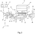
- a device 31 is provided, which is shown in a schematic view in figure 3 is shown.
- This device 31 consists of a gripping device 34 and a workpiece carrier 35 and a cutting tool 36 as well as a device 37 for connecting, in particular for clawing, the tab 23 to the data carrier 24, preferably a laminating and welding device 37.
- the workpiece carrier 35 has a support surface 41 and alignment elements 42, by which a data carrier 34 placed on the workpiece carrier 35 is aligned.
- the gripping device 34 is positioned adjacent to the workpiece carrier 35 .
- This gripping device 34 comprises a first gripping element 44, a second gripping element 46 and a third gripping element 48.
- the first gripping element 41 is assigned a feed device 33, via which the flexible strip material 26 is fed to the device 31.
- the feed device 33 can be formed by one or more feed rollers. Upstream of the feed device 33 is preferably one Splicing device 51 is provided, through which a web end of a used roll 52 can be connected to a web beginning of a new roll 53 with flexible strip material 56, so that an endless strip for feeding the flexible strip material 26 to the device 31 can be created.
- a sealing device 61 is preferably provided between the feed device 33 and the gripping device 34 .
- This sealing device 61 can comprise, for example, two ultrasonic stamps directed towards one another, in particular a sonotrode directed towards an anvil.
- This sealing device 61 allows a section of the flexible strip material 26 or the individual fibers of the flexible strip material 26 to be fused together. It is provided that this sealing area is incorporated in the flexible strip material 26 in such a way that these sealing sections are aligned with a front and rear or upper and lower narrow side of the data carrier 24 after the tab 23 has been attached. This has the advantage that when the data carrier 24 with the tab 23 connected to it is punched to a final format, the fibers of the flexible strip material 26 can be prevented from fanning out in the cutting area.
- a marking device 65 can be provided between the feed device 33 and the gripping device 34 .
- markings and/or individual information and/or personalized information can be applied or introduced.
- the marking device 65 can be implemented by printing with ink or the like, using lasers and/or stamps.
- the first gripping element 44 of the gripping device 34 is assigned to a working space 55 on the input side.
- a free end 56 of the flexible strip material 26 is positioned in relation to the first gripping element 44 in such a way that there is a projection 57 in the direction of the second gripping element 46 .
- This supernatant 57 can up up to 20 millimeters.
- the second gripping element 46 is positioned opposite the first gripping element 44 as seen in the longitudinal direction of the flexible strip material 26 fed to the first gripping element 44 .
- a width of gripping jaws of the first and second gripping members 44, 46 is equal to or greater than the width of the flexible strip material 26.
- the third gripping element 48 can be positioned so that it can be moved, preferably transversely to the first and second gripping element.
- the third gripping element 48 can be moved towards the workpiece carrier 35 and positioned adjacent to it.
- the third gripping element 48 preferably has at least one travel axis in the Y and Z direction.
- the laminating or welding device 37 is positioned above the workpiece carrier 35 and can be moved at least along the Z-axis and moved towards the workpiece carrier 35 .
- the second gripping element 46 is preferably driven to be movable in and counter to the X-direction and can be adjusted at least in height.
- a cutting tool 36 is positioned between the first gripping member 44 and the third gripping member 48 . This can preferably be designed as an ultrasonic cutting tool, so that the cut ends of the flexible strip material 26 are welded or closed, so that the flexible strip material 26 is prevented from fanning out.
- the feed device 33 can be connected to an aligning unit.
- the first gripping element 44 and the second gripping element 46 can also be adjustable transversely to the longitudinal direction of the tape, ie in the Y direction, in order to enable the flexible tape material 26 to be aligned with the data carrier 24 .
- the workpiece carrier 35 can have an alignment unit in order to enable an adjustment to the longitudinal direction of the strip of the flexible strip material 26 .
- the angular position of the laminating and welding device 37 in relation to the workpiece carrier 35 can be adjusted be to allow alignment in the tape longitudinal direction of the flexible tape material 26.
- FIG 4 a starting position for the automated production of the data page 17 is shown. To set up this starting position, it is first necessary for the end 56 of the flexible strip material 26 to be positioned in relation to the first gripping element 44 with an overhang in the direction of the second gripping element 46 . Subsequently, the first gripping element 44 is closed. Starting from this starting position, the automation process can begin. The second gripping element 46 is moved towards the first gripping element 44 and grips the overhang 57 of the flexible strip material 26 on the first gripping element 44.
- the next step is in figure 5 shown.
- the second gripping element 46 is closed.
- the first gripping element 44 is opened.
- the second gripping element 46 is moved through the working space 55 into a working position 58 .
- This working position is in figure 6 shown.
- the assumption of the working position 58 by the second gripping element 46 is monitored with a position monitor, in particular a sensor 59 .
- the flexible strip material 46 is pulled off the feed device 33 under tension.
- the first gripping element 44 is closed.
- the third gripping element 48 is positioned in an open state to the flexible strip material 26 held taut between the first and second gripping elements 44, 46 ( figure 7 ).
- an infeed movement of the third gripping element 48 is controlled, so that the flexible strip material 26 can be gripped by gripping jaws 49 of the third gripping element 48 in relation to the protruding region 29 of the tab 23 .
- the second gripping element 46 moves in the direction of the first gripping element 44 moved towards. this is in figure 8 shown. This relaxes the flexible band material 26 and only keeps it stretched. The movement can be less than or equal to two millimeters, in particular less than or equal to one millimeter.
- the third gripping element 48 is then closed.
- the length of the gripping jaws 49 of the third gripping element 48 preferably corresponds to the length of the tab 23 to be attached.
- the flexible strip material 26 is cut to length by the cutting tool 36 .
- this is in figure 9 shown. This incision can be made in such a way that a projection 57 remains on the first gripping element 44 in the direction of the second gripping element 46 .
- the cutting tool 39 can be positioned close to the first gripping element 44 .
- the first gripping element 44 is then closed and again moved in the direction of a working space 55, ie in the direction of the workpiece carrier 34, so that a starting position is achieved in which the second gripping element 46 can grip the overhang 57.
- the overhang 57 is preferably selected in such a way that it protrudes into the working space 55 in relation to an opened cutting tool 39 , so that the second gripping element 46 can grip the overhang 57 .
- the third gripping element 48 as shown in figure 10 is shown, is moved in the direction of the workpiece carrier 35 . This can be a superimposed movement against the Z direction and in the Y direction. As a result of this displacement movement, the connection area 27 of the flexible strip material 26 is positioned in relation to the edge area 24 of the data carrier 24 to form the overlapping area 28 on the data carrier 24 and is held in this position.
- a laminating or welding device 37 is fed onto the tool carrier 35 and the tab 23 is permanently connected to the data carrier 24 .
- An ultrasonic probe is preferably provided, which acts on the flexible strip material 26 in order to connect it to the data carrier 35. Then the laminating or welding device 37 is lifted, the third gripping element 48 is opened and returned to a starting position. this is in figure 12 shown.
- the finished data page 17 can then be removed from the workpiece carrier 35 manually or preferably automatically with a handling device. Simultaneously or subsequently, the data carrier 24, which is preferably provided in a magazine, can be placed and aligned on the workpiece carrier 35 with a handling device or manually. The method can then start again with the first method step according to FIG figure 4 start. 11. document 36 cutting tool 61 sealing device 12. book cover 37 laminating or welding device 62 13.
Landscapes
- Engineering & Computer Science (AREA)
- Manufacturing & Machinery (AREA)
- Mechanical Engineering (AREA)
- Folding Of Thin Sheet-Like Materials, Special Discharging Devices, And Others (AREA)
- Making Paper Articles (AREA)
Applications Claiming Priority (1)
| Application Number | Priority Date | Filing Date | Title |
|---|---|---|---|
| DE102021115153.8A DE102021115153B4 (de) | 2021-06-11 | 2021-06-11 | Verfahren und Vorrichtung zur Herstellung einer Datenseite für ein buchartiges Dokument |
Publications (2)
| Publication Number | Publication Date |
|---|---|
| EP4101655A1 true EP4101655A1 (fr) | 2022-12-14 |
| EP4101655B1 EP4101655B1 (fr) | 2023-11-01 |
Family
ID=81653582
Family Applications (1)
| Application Number | Title | Priority Date | Filing Date |
|---|---|---|---|
| EP22173151.6A Active EP4101655B1 (fr) | 2021-06-11 | 2022-05-13 | Procédé et dispositif de production d'une page de données pour un document de type livre |
Country Status (2)
| Country | Link |
|---|---|
| EP (1) | EP4101655B1 (fr) |
| DE (1) | DE102021115153B4 (fr) |
Citations (5)
| Publication number | Priority date | Publication date | Assignee | Title |
|---|---|---|---|---|
| JP2005186373A (ja) * | 2003-12-25 | 2005-07-14 | Tadao Uno | 電子パスポート |
| DE102012112383A1 (de) * | 2012-12-17 | 2014-06-18 | Bundesdruckerei Gmbh | Verfahren und Vorrichtung zur Herstellung einer Datenseite für ein buchartiges Dokument |
| DE102016218047A1 (de) * | 2016-09-20 | 2018-03-22 | Bundesdruckerei Gmbh | Verfahren, Vorrichtung und System zur Herstellung eines buchförmigen Ausweis-, Wert- oder Sicherheitsdokument und buchförmiges Ausweis-, Wert- oder Sicherheitsdokument |
| DE102016218040A1 (de) | 2016-09-20 | 2018-03-22 | Bundesdruckerei Gmbh | Vorrichtung und ein Verfahren zur Herstellung einer Datenkarte für ein buchartigen Ausweis-, Wert- oder Sicherheitsdokument, System und Verfahren zur Herstellung eines buchförmigen Ausweis-, Wert- oder Sicherheitsdokument und Datenkarte für ein Ausweis-, Wert- oder Sicherheitsdokument |
| EP3587137A1 (fr) * | 2018-06-15 | 2020-01-01 | Bundesdruckerei GmbH | Dispositif de manipulation et procédé d'insertion de parties de document dans un dispositif de traitement ultérieur |
-
2021
- 2021-06-11 DE DE102021115153.8A patent/DE102021115153B4/de not_active Expired - Fee Related
-
2022
- 2022-05-13 EP EP22173151.6A patent/EP4101655B1/fr active Active
Patent Citations (6)
| Publication number | Priority date | Publication date | Assignee | Title |
|---|---|---|---|---|
| JP2005186373A (ja) * | 2003-12-25 | 2005-07-14 | Tadao Uno | 電子パスポート |
| DE102012112383A1 (de) * | 2012-12-17 | 2014-06-18 | Bundesdruckerei Gmbh | Verfahren und Vorrichtung zur Herstellung einer Datenseite für ein buchartiges Dokument |
| EP2931526B1 (fr) | 2012-12-17 | 2017-05-17 | Bundesdruckerei GmbH | Procédé et dispositif pour la confection d'une page de données pour un document de type livre |
| DE102016218047A1 (de) * | 2016-09-20 | 2018-03-22 | Bundesdruckerei Gmbh | Verfahren, Vorrichtung und System zur Herstellung eines buchförmigen Ausweis-, Wert- oder Sicherheitsdokument und buchförmiges Ausweis-, Wert- oder Sicherheitsdokument |
| DE102016218040A1 (de) | 2016-09-20 | 2018-03-22 | Bundesdruckerei Gmbh | Vorrichtung und ein Verfahren zur Herstellung einer Datenkarte für ein buchartigen Ausweis-, Wert- oder Sicherheitsdokument, System und Verfahren zur Herstellung eines buchförmigen Ausweis-, Wert- oder Sicherheitsdokument und Datenkarte für ein Ausweis-, Wert- oder Sicherheitsdokument |
| EP3587137A1 (fr) * | 2018-06-15 | 2020-01-01 | Bundesdruckerei GmbH | Dispositif de manipulation et procédé d'insertion de parties de document dans un dispositif de traitement ultérieur |
Also Published As
| Publication number | Publication date |
|---|---|
| DE102021115153B4 (de) | 2023-11-09 |
| EP4101655B1 (fr) | 2023-11-01 |
| DE102021115153A1 (de) | 2022-12-15 |
Similar Documents
| Publication | Publication Date | Title |
|---|---|---|
| EP2931526B1 (fr) | Procédé et dispositif pour la confection d'une page de données pour un document de type livre | |
| EP3702169B1 (fr) | Procédé de fabrication d'un demi-produit ainsi que demi-produit | |
| EP2393660B1 (fr) | Procédé de fabrication de produits de sécurité multicouches | |
| DE102016218046B4 (de) | Verfahren, Vorrichtung und System zur Herstellung eines buchartigen Ausweis-, Wert- oder Sicherheitsdokument und buchartiges Ausweis-, Wert- oder Sicherheitsdokument | |
| EP3515723B1 (fr) | Procédé, dispositif et système permettant de produire un document d'identité, de valeur ou de sécurité en forme de livret | |
| DE102005039214A1 (de) | Verfahren zum Verbinden des Stoß von Dichtungsprofilen sowie Vorrichtung zu dessen Durchführung | |
| DE102016201976B3 (de) | Vorrichtung und Verfahren zur Bearbeitung eines Substrats | |
| DE10013224A1 (de) | Verfahren und Vorrichtung zum Aufbringen von selbstklebenden Folienzuschnitten, insbesondere auf Kfz-Karosserieteile | |
| EP3515722B1 (fr) | Dispositif et procédé pour fabriquer une carte de données pour un document d'identité, document de valeur ou document de sécurité sous forme de livret, système et procédé pour fabriquer un document d'identité, document de valeur ou document de sécurité sous forme de livret et carte de données pour un document d'identité, document de valeur ou document de sécurité sous forme de livret | |
| EP3368333A1 (fr) | Page de données, notamment pour un document de type livre, et son procédé de production | |
| EP4101655B1 (fr) | Procédé et dispositif de production d'une page de données pour un document de type livre | |
| EP3339050B1 (fr) | Languette, page de données, bloc de livre, document de type livre ainsi que leur procédé de fabrication | |
| EP3489028B1 (fr) | Procédé de fabrication d'un document de valeur et / ou de sécurité de type livre ainsi que document de valeur et / ou de sécurité de type livre | |
| EP3680112A1 (fr) | Composite à partir d'une feuille support et d'au moins une couche adhésive appliquée, procédé de fabrication d'un demi-produit doté d'un tel composite et demi-produit | |
| EP3556567B1 (fr) | Procédé et dispositif d'application d'une section de feuille adhésive séparée d'une bande adhésive à une couverture de livre | |
| EP4215380B1 (fr) | Installation de production et procédé de production d'une carte brute ou d'un composite de cartes brutes pour documents d'identité, de valeur ou de sécurité | |
| EP3515717B1 (fr) | Dispositif de regroupement et procédé permettant de séparer et de trier des doubles pages | |
| DE102016218045B4 (de) | Verfahren und Vorrichtung zur Herstellung eines Passbuchblocks für ein buchartigen Ausweis-, Wert- oder Sicherheitsdokument, System zur Herstellung eines buchartigen Ausweis-, Wert- oder Sicherheitsdokument und buchartiges Ausweis-, Wert- oder Sicherheitsdokument | |
| EP3509868B1 (fr) | Procédé de fabrication d'un corps composite | |
| DE102018128104B4 (de) | Verfahren zur Herstellung einer Datenseite sowie Datenseite für ein buchartiges Dokument und Vorrichtung zur Herstellung einer solchen Datenseite | |
| DE102018106126A1 (de) | Herstellung eines buchförmigen Ausweis-, Wert- oder Sicherheitsdokumentes mittels Fräsens | |
| EP3636437A1 (fr) | Procédé de montage d'une plaque d'impression à un cylindre d'impression, dispositif d'application d'une plaque d'impression à un cylindre d'impression, procédé de fabrication d'une plaque d'impression, plaque d'impression destinée à l'utilisation dans un procédé de flexographie et dispositif de coupage des bords d'une plaque d'impression | |
| EP3339046B1 (fr) | Support de données ainsi que procédé et dispositif de fabrication d'un tel support de données pour un document de type livre | |
| DE102016015556B4 (de) | Verfahren zur Herstellung eines Datenträgers für ein buchförmiges Wert und/oder Sicherheitsdokument | |
| EP4212350A1 (fr) | Dispositif d'impression pour imprimer un substrat en forme de bande |
Legal Events
| Date | Code | Title | Description |
|---|---|---|---|
| PUAI | Public reference made under article 153(3) epc to a published international application that has entered the european phase |
Free format text: ORIGINAL CODE: 0009012 |
|
| STAA | Information on the status of an ep patent application or granted ep patent |
Free format text: STATUS: THE APPLICATION HAS BEEN PUBLISHED |
|
| AK | Designated contracting states |
Kind code of ref document: A1 Designated state(s): AL AT BE BG CH CY CZ DE DK EE ES FI FR GB GR HR HU IE IS IT LI LT LU LV MC MK MT NL NO PL PT RO RS SE SI SK SM TR |
|
| STAA | Information on the status of an ep patent application or granted ep patent |
Free format text: STATUS: REQUEST FOR EXAMINATION WAS MADE |
|
| 17P | Request for examination filed |
Effective date: 20230418 |
|
| RBV | Designated contracting states (corrected) |
Designated state(s): AL AT BE BG CH CY CZ DE DK EE ES FI FR GB GR HR HU IE IS IT LI LT LU LV MC MK MT NL NO PL PT RO RS SE SI SK SM TR |
|
| GRAP | Despatch of communication of intention to grant a patent |
Free format text: ORIGINAL CODE: EPIDOSNIGR1 |
|
| STAA | Information on the status of an ep patent application or granted ep patent |
Free format text: STATUS: GRANT OF PATENT IS INTENDED |
|
| INTG | Intention to grant announced |
Effective date: 20230607 |
|
| P01 | Opt-out of the competence of the unified patent court (upc) registered |
Effective date: 20230526 |
|
| GRAS | Grant fee paid |
Free format text: ORIGINAL CODE: EPIDOSNIGR3 |
|
| GRAA | (expected) grant |
Free format text: ORIGINAL CODE: 0009210 |
|
| STAA | Information on the status of an ep patent application or granted ep patent |
Free format text: STATUS: THE PATENT HAS BEEN GRANTED |
|
| AK | Designated contracting states |
Kind code of ref document: B1 Designated state(s): AL AT BE BG CH CY CZ DE DK EE ES FI FR GB GR HR HU IE IS IT LI LT LU LV MC MK MT NL NO PL PT RO RS SE SI SK SM TR |
|
| REG | Reference to a national code |
Ref country code: GB Ref legal event code: FG4D Free format text: NOT ENGLISH |
|
| REG | Reference to a national code |
Ref country code: CH Ref legal event code: EP |
|
| REG | Reference to a national code |
Ref country code: DE Ref legal event code: R096 Ref document number: 502022000232 Country of ref document: DE |
|
| REG | Reference to a national code |
Ref country code: IE Ref legal event code: FG4D Free format text: LANGUAGE OF EP DOCUMENT: GERMAN |
|
| REG | Reference to a national code |
Ref country code: LT Ref legal event code: MG9D |
|
| REG | Reference to a national code |
Ref country code: NL Ref legal event code: MP Effective date: 20231101 |
|
| PG25 | Lapsed in a contracting state [announced via postgrant information from national office to epo] |
Ref country code: GR Free format text: LAPSE BECAUSE OF FAILURE TO SUBMIT A TRANSLATION OF THE DESCRIPTION OR TO PAY THE FEE WITHIN THE PRESCRIBED TIME-LIMIT Effective date: 20240202 |
|
| PG25 | Lapsed in a contracting state [announced via postgrant information from national office to epo] |
Ref country code: IS Free format text: LAPSE BECAUSE OF FAILURE TO SUBMIT A TRANSLATION OF THE DESCRIPTION OR TO PAY THE FEE WITHIN THE PRESCRIBED TIME-LIMIT Effective date: 20240301 |
|
| PG25 | Lapsed in a contracting state [announced via postgrant information from national office to epo] |
Ref country code: LT Free format text: LAPSE BECAUSE OF FAILURE TO SUBMIT A TRANSLATION OF THE DESCRIPTION OR TO PAY THE FEE WITHIN THE PRESCRIBED TIME-LIMIT Effective date: 20231101 |
|
| PG25 | Lapsed in a contracting state [announced via postgrant information from national office to epo] |
Ref country code: NL Free format text: LAPSE BECAUSE OF FAILURE TO SUBMIT A TRANSLATION OF THE DESCRIPTION OR TO PAY THE FEE WITHIN THE PRESCRIBED TIME-LIMIT Effective date: 20231101 |
|
| PG25 | Lapsed in a contracting state [announced via postgrant information from national office to epo] |
Ref country code: ES Free format text: LAPSE BECAUSE OF FAILURE TO SUBMIT A TRANSLATION OF THE DESCRIPTION OR TO PAY THE FEE WITHIN THE PRESCRIBED TIME-LIMIT Effective date: 20231101 |
|
| PG25 | Lapsed in a contracting state [announced via postgrant information from national office to epo] |
Ref country code: NL Free format text: LAPSE BECAUSE OF FAILURE TO SUBMIT A TRANSLATION OF THE DESCRIPTION OR TO PAY THE FEE WITHIN THE PRESCRIBED TIME-LIMIT Effective date: 20231101 Ref country code: LT Free format text: LAPSE BECAUSE OF FAILURE TO SUBMIT A TRANSLATION OF THE DESCRIPTION OR TO PAY THE FEE WITHIN THE PRESCRIBED TIME-LIMIT Effective date: 20231101 Ref country code: IS Free format text: LAPSE BECAUSE OF FAILURE TO SUBMIT A TRANSLATION OF THE DESCRIPTION OR TO PAY THE FEE WITHIN THE PRESCRIBED TIME-LIMIT Effective date: 20240301 Ref country code: GR Free format text: LAPSE BECAUSE OF FAILURE TO SUBMIT A TRANSLATION OF THE DESCRIPTION OR TO PAY THE FEE WITHIN THE PRESCRIBED TIME-LIMIT Effective date: 20240202 Ref country code: ES Free format text: LAPSE BECAUSE OF FAILURE TO SUBMIT A TRANSLATION OF THE DESCRIPTION OR TO PAY THE FEE WITHIN THE PRESCRIBED TIME-LIMIT Effective date: 20231101 Ref country code: BG Free format text: LAPSE BECAUSE OF FAILURE TO SUBMIT A TRANSLATION OF THE DESCRIPTION OR TO PAY THE FEE WITHIN THE PRESCRIBED TIME-LIMIT Effective date: 20240201 Ref country code: PT Free format text: LAPSE BECAUSE OF FAILURE TO SUBMIT A TRANSLATION OF THE DESCRIPTION OR TO PAY THE FEE WITHIN THE PRESCRIBED TIME-LIMIT Effective date: 20240301 |
|
| PG25 | Lapsed in a contracting state [announced via postgrant information from national office to epo] |
Ref country code: SE Free format text: LAPSE BECAUSE OF FAILURE TO SUBMIT A TRANSLATION OF THE DESCRIPTION OR TO PAY THE FEE WITHIN THE PRESCRIBED TIME-LIMIT Effective date: 20231101 Ref country code: RS Free format text: LAPSE BECAUSE OF FAILURE TO SUBMIT A TRANSLATION OF THE DESCRIPTION OR TO PAY THE FEE WITHIN THE PRESCRIBED TIME-LIMIT Effective date: 20231101 Ref country code: PL Free format text: LAPSE BECAUSE OF FAILURE TO SUBMIT A TRANSLATION OF THE DESCRIPTION OR TO PAY THE FEE WITHIN THE PRESCRIBED TIME-LIMIT Effective date: 20231101 Ref country code: NO Free format text: LAPSE BECAUSE OF FAILURE TO SUBMIT A TRANSLATION OF THE DESCRIPTION OR TO PAY THE FEE WITHIN THE PRESCRIBED TIME-LIMIT Effective date: 20240201 Ref country code: LV Free format text: LAPSE BECAUSE OF FAILURE TO SUBMIT A TRANSLATION OF THE DESCRIPTION OR TO PAY THE FEE WITHIN THE PRESCRIBED TIME-LIMIT Effective date: 20231101 Ref country code: HR Free format text: LAPSE BECAUSE OF FAILURE TO SUBMIT A TRANSLATION OF THE DESCRIPTION OR TO PAY THE FEE WITHIN THE PRESCRIBED TIME-LIMIT Effective date: 20231101 |
|
| PG25 | Lapsed in a contracting state [announced via postgrant information from national office to epo] |
Ref country code: DK Free format text: LAPSE BECAUSE OF FAILURE TO SUBMIT A TRANSLATION OF THE DESCRIPTION OR TO PAY THE FEE WITHIN THE PRESCRIBED TIME-LIMIT Effective date: 20231101 |
|
| PG25 | Lapsed in a contracting state [announced via postgrant information from national office to epo] |
Ref country code: CZ Free format text: LAPSE BECAUSE OF FAILURE TO SUBMIT A TRANSLATION OF THE DESCRIPTION OR TO PAY THE FEE WITHIN THE PRESCRIBED TIME-LIMIT Effective date: 20231101 |
|
| PG25 | Lapsed in a contracting state [announced via postgrant information from national office to epo] |
Ref country code: SK Free format text: LAPSE BECAUSE OF FAILURE TO SUBMIT A TRANSLATION OF THE DESCRIPTION OR TO PAY THE FEE WITHIN THE PRESCRIBED TIME-LIMIT Effective date: 20231101 |
|
| PG25 | Lapsed in a contracting state [announced via postgrant information from national office to epo] |
Ref country code: SM Free format text: LAPSE BECAUSE OF FAILURE TO SUBMIT A TRANSLATION OF THE DESCRIPTION OR TO PAY THE FEE WITHIN THE PRESCRIBED TIME-LIMIT Effective date: 20231101 Ref country code: SK Free format text: LAPSE BECAUSE OF FAILURE TO SUBMIT A TRANSLATION OF THE DESCRIPTION OR TO PAY THE FEE WITHIN THE PRESCRIBED TIME-LIMIT Effective date: 20231101 Ref country code: IT Free format text: LAPSE BECAUSE OF FAILURE TO SUBMIT A TRANSLATION OF THE DESCRIPTION OR TO PAY THE FEE WITHIN THE PRESCRIBED TIME-LIMIT Effective date: 20231101 Ref country code: EE Free format text: LAPSE BECAUSE OF FAILURE TO SUBMIT A TRANSLATION OF THE DESCRIPTION OR TO PAY THE FEE WITHIN THE PRESCRIBED TIME-LIMIT Effective date: 20231101 Ref country code: DK Free format text: LAPSE BECAUSE OF FAILURE TO SUBMIT A TRANSLATION OF THE DESCRIPTION OR TO PAY THE FEE WITHIN THE PRESCRIBED TIME-LIMIT Effective date: 20231101 Ref country code: CZ Free format text: LAPSE BECAUSE OF FAILURE TO SUBMIT A TRANSLATION OF THE DESCRIPTION OR TO PAY THE FEE WITHIN THE PRESCRIBED TIME-LIMIT Effective date: 20231101 |
|
| REG | Reference to a national code |
Ref country code: DE Ref legal event code: R097 Ref document number: 502022000232 Country of ref document: DE |
|
| PLBE | No opposition filed within time limit |
Free format text: ORIGINAL CODE: 0009261 |
|
| STAA | Information on the status of an ep patent application or granted ep patent |
Free format text: STATUS: NO OPPOSITION FILED WITHIN TIME LIMIT |
|
| 26N | No opposition filed |
Effective date: 20240802 |
|
| PG25 | Lapsed in a contracting state [announced via postgrant information from national office to epo] |
Ref country code: SI Free format text: LAPSE BECAUSE OF FAILURE TO SUBMIT A TRANSLATION OF THE DESCRIPTION OR TO PAY THE FEE WITHIN THE PRESCRIBED TIME-LIMIT Effective date: 20231101 |
|
| PG25 | Lapsed in a contracting state [announced via postgrant information from national office to epo] |
Ref country code: SI Free format text: LAPSE BECAUSE OF FAILURE TO SUBMIT A TRANSLATION OF THE DESCRIPTION OR TO PAY THE FEE WITHIN THE PRESCRIBED TIME-LIMIT Effective date: 20231101 |
|
| PG25 | Lapsed in a contracting state [announced via postgrant information from national office to epo] |
Ref country code: MC Free format text: LAPSE BECAUSE OF FAILURE TO SUBMIT A TRANSLATION OF THE DESCRIPTION OR TO PAY THE FEE WITHIN THE PRESCRIBED TIME-LIMIT Effective date: 20231101 |
|
| PG25 | Lapsed in a contracting state [announced via postgrant information from national office to epo] |
Ref country code: LU Free format text: LAPSE BECAUSE OF NON-PAYMENT OF DUE FEES Effective date: 20240513 |
|
| PG25 | Lapsed in a contracting state [announced via postgrant information from national office to epo] |
Ref country code: MC Free format text: LAPSE BECAUSE OF FAILURE TO SUBMIT A TRANSLATION OF THE DESCRIPTION OR TO PAY THE FEE WITHIN THE PRESCRIBED TIME-LIMIT Effective date: 20231101 Ref country code: LU Free format text: LAPSE BECAUSE OF NON-PAYMENT OF DUE FEES Effective date: 20240513 |
|
| REG | Reference to a national code |
Ref country code: BE Ref legal event code: MM Effective date: 20240531 |
|
| PG25 | Lapsed in a contracting state [announced via postgrant information from national office to epo] |
Ref country code: IE Free format text: LAPSE BECAUSE OF NON-PAYMENT OF DUE FEES Effective date: 20240513 |
|
| PG25 | Lapsed in a contracting state [announced via postgrant information from national office to epo] |
Ref country code: BE Free format text: LAPSE BECAUSE OF NON-PAYMENT OF DUE FEES Effective date: 20240531 |
|
| PGFP | Annual fee paid to national office [announced via postgrant information from national office to epo] |
Ref country code: DE Payment date: 20250519 Year of fee payment: 4 |
|
| PGFP | Annual fee paid to national office [announced via postgrant information from national office to epo] |
Ref country code: FR Payment date: 20250523 Year of fee payment: 4 |
|
| PGFP | Annual fee paid to national office [announced via postgrant information from national office to epo] |
Ref country code: AT Payment date: 20250721 Year of fee payment: 4 |
|
| PG25 | Lapsed in a contracting state [announced via postgrant information from national office to epo] |
Ref country code: RO Free format text: LAPSE BECAUSE OF FAILURE TO SUBMIT A TRANSLATION OF THE DESCRIPTION OR TO PAY THE FEE WITHIN THE PRESCRIBED TIME-LIMIT Effective date: 20231101 |
|
| PG25 | Lapsed in a contracting state [announced via postgrant information from national office to epo] |
Ref country code: CY Free format text: LAPSE BECAUSE OF FAILURE TO SUBMIT A TRANSLATION OF THE DESCRIPTION OR TO PAY THE FEE WITHIN THE PRESCRIBED TIME-LIMIT; INVALID AB INITIO Effective date: 20220513 |
|
| PG25 | Lapsed in a contracting state [announced via postgrant information from national office to epo] |
Ref country code: HU Free format text: LAPSE BECAUSE OF FAILURE TO SUBMIT A TRANSLATION OF THE DESCRIPTION OR TO PAY THE FEE WITHIN THE PRESCRIBED TIME-LIMIT; INVALID AB INITIO Effective date: 20220513 |
|
| PG25 | Lapsed in a contracting state [announced via postgrant information from national office to epo] |
Ref country code: FI Free format text: LAPSE BECAUSE OF FAILURE TO SUBMIT A TRANSLATION OF THE DESCRIPTION OR TO PAY THE FEE WITHIN THE PRESCRIBED TIME-LIMIT Effective date: 20231101 |
|
| REG | Reference to a national code |
Ref country code: CH Ref legal event code: H13 Free format text: ST27 STATUS EVENT CODE: U-0-0-H10-H13 (AS PROVIDED BY THE NATIONAL OFFICE) Effective date: 20251223 |
|
| PG25 | Lapsed in a contracting state [announced via postgrant information from national office to epo] |
Ref country code: CH Free format text: LAPSE BECAUSE OF NON-PAYMENT OF DUE FEES Effective date: 20250531 |
|
| PGFP | Annual fee paid to national office [announced via postgrant information from national office to epo] |
Ref country code: GB Payment date: 20260324 Year of fee payment: 5 |