EP4101706A2 - Entraînement de pied d'appui pour une remorque de véhicule, support de remorque pour une remorque de véhicule, remorque de véhicule et procédé de mise à niveau d'un entraînement de pied d'appui sur une remorque de véhicule - Google Patents
Entraînement de pied d'appui pour une remorque de véhicule, support de remorque pour une remorque de véhicule, remorque de véhicule et procédé de mise à niveau d'un entraînement de pied d'appui sur une remorque de véhicule Download PDFInfo
- Publication number
- EP4101706A2 EP4101706A2 EP22175505.1A EP22175505A EP4101706A2 EP 4101706 A2 EP4101706 A2 EP 4101706A2 EP 22175505 A EP22175505 A EP 22175505A EP 4101706 A2 EP4101706 A2 EP 4101706A2
- Authority
- EP
- European Patent Office
- Prior art keywords
- landing gear
- vehicle trailer
- shaft attachment
- trailer
- support
- Prior art date
- Legal status (The legal status is an assumption and is not a legal conclusion. Google has not performed a legal analysis and makes no representation as to the accuracy of the status listed.)
- Granted
Links
Images


Classifications
-
- B—PERFORMING OPERATIONS; TRANSPORTING
- B60—VEHICLES IN GENERAL
- B60S—SERVICING, CLEANING, REPAIRING, SUPPORTING, LIFTING, OR MANOEUVRING OF VEHICLES, NOT OTHERWISE PROVIDED FOR
- B60S9/00—Ground-engaging vehicle fittings for supporting, lifting, or manoeuvring the vehicle, wholly or in part, e.g. built-in jacks
- B60S9/02—Ground-engaging vehicle fittings for supporting, lifting, or manoeuvring the vehicle, wholly or in part, e.g. built-in jacks for only lifting or supporting
- B60S9/04—Ground-engaging vehicle fittings for supporting, lifting, or manoeuvring the vehicle, wholly or in part, e.g. built-in jacks for only lifting or supporting mechanically
- B60S9/06—Ground-engaging vehicle fittings for supporting, lifting, or manoeuvring the vehicle, wholly or in part, e.g. built-in jacks for only lifting or supporting mechanically of screw-and-nut type
- B60S9/08—Ground-engaging vehicle fittings for supporting, lifting, or manoeuvring the vehicle, wholly or in part, e.g. built-in jacks for only lifting or supporting mechanically of screw-and-nut type the screw axis being substantially vertical
-
- B—PERFORMING OPERATIONS; TRANSPORTING
- B60—VEHICLES IN GENERAL
- B60D—VEHICLE CONNECTIONS
- B60D1/00—Traction couplings; Hitches; Draw-gear; Towing devices
- B60D1/58—Auxiliary devices
- B60D1/66—Props
Definitions
- the invention relates to a landing gear drive for a vehicle trailer.
- the invention relates to a trailer support for a vehicle trailer, a vehicle trailer and a method for retrofitting a landing gear drive on a vehicle trailer.
- the trailer support often has a manually operated crank with which the supports can be moved. However, this requires a lot of strength and a lot of time.
- electrically driven landing gear drives are known from the prior art, for example EP 1 159 171 B1 that are built into or attached to the vehicle trailer and facilitate the extension and retraction of the supports.
- EP 0 529 544 B1 it is therefore provided to connect a motor drive while retaining a crank with an additional input of the crank drive in order to obtain a failsafe.
- the object of the invention is to specify a landing gear drive for a vehicle trailer, a trailer support for a vehicle trailer, a vehicle trailer and a method for retrofitting a landing gear drive to a vehicle trailer, which achieve high reliability and are easy to operate and handle.
- a landing gear drive for a vehicle trailer comprising a shaft attachment, an electric motor and a gear
- the shaft attachment being designed to be placed on a landing gear shaft of the vehicle trailer in a rotationally secured manner, the gear receiving a torque from the electric motor and transmitted to the shaft attachment by a mechanical connection
- the mechanical connection between the transmission and the shaft attachment is provided by a coupling element, the coupling element being arranged on the shaft attachment and such is configured such that the mechanical connection between the transmission and the shaft attachment is interrupted by attaching a crank to an outer end of the shaft attachment.
- the landing gear shaft can be operated both electrically and manually.
- the landing gear drive enables easy switching between electrical operation and manual operation, for example if the electric motor fails.
- the crank By placing the crank, the mechanical connection formed by the coupling element between the gear and shaft attachment is released, so that the self-locking of the worm gear is canceled.
- the support winch shaft and thus the support can be driven manually by means of the crank without the gear making it difficult to operate the crank.
- the crank is also attached to the same side as the landing gear drive. When changing from electric operation to manual operation, the driver does not have to change sides of the vehicle.
- the vehicle trailer is in particular a semi-trailer or a one-, two- or three-axle trailer that requires support in the form of supports.
- any existing crank is removed from the landing gear shaft before the landing gear drive is installed over the landing gear shaft.
- the landing gear drive comprises a crank which is designed to be placed on the outer end of the shaft attachment and to manually drive the landing gear.
- the shaft attachment connects the landing gear drive to the landing gear shaft, allowing the torque of the electric motor to be transferred to the landing gear shaft.
- the shaft attachment By placing the shaft attachment on the landing gear shaft, the landing gear shaft is lengthened in the longitudinal axial direction. In this way it is possible to couple the landing gear shaft to the gearbox and at the same time put a crank on the outer end.
- the shaft attachment has a cylindrical first section and a second section adjoining it in the form of a hollow cylinder, the circumference of the second section being greater than the circumference of the first section.
- the second section is designed in particular to accommodate the landing gear shaft and the first section to accommodate the coupling element.
- the design of the coupling element as a key is a particularly effective and simple way to detachably couple the transmission to the shaft attachment.
- the feather key protrudes from the shaft attachment in the radial direction and lies in the groove of the gear hub, so that the torque of the gear is transmitted to the shaft attachment.
- the feather key is pressed inwards in the radial direction so that the feather key leaves the groove of the gear hub and the mechanical connection is released.
- the feather key is connected to the shaft attachment in the radial direction by at least one spring element, which provides the elastic deflectability of the feather key.
- the feather key extends, in particular, longitudinally axially to the support winch shaft when the shaft attachment is placed on the support winch shaft.
- the feather key is coupled to the shaft attachment in particular by a form fit, the feather key being arranged in a groove of the shaft attachment in particular to produce the form fit.
- radial or in the radial direction, longitudinally axial or in the longitudinally axial direction and in the circumferential direction each relate to the reference system of the shaft attachment. When the shaft attachment is placed on the landing gear shaft, these directions also refer to the reference system of the landing gear shaft.
- the feather key is preferably ramp-shaped at its outer end.
- the crank moves along the ramped outer end of the feather key and presses it onto it way inside.
- a straight section adjoins the ramp-shaped outer end of the feather key. This straight section ensures that the key is pressed in evenly when the crank is pushed on.
- the feather key is preferably formed in two parts, with a first component being fixed in the radial direction on a second component, with the outer end of the first component in particular being ramp-shaped, with the second component in particular having a greater longitudinal extension than the first component.
- the two-part design of the feather key allows easy assembly of the feather key on the shaft attachment.
- the first component comprises the ramped end and is in contact with the crank when the crank is attached.
- the second component is arranged in particular in a groove of the shaft attachment.
- the groove of the shaft attachment encloses the parallel key in the circumferential direction.
- the outer end of the key is the end that faces away from the vehicle trailer when the landing gear drive is fixed to the vehicle trailer and the shaft attachment is placed on the landing gear shaft.
- the housing is designed to protect the components of the landing gear drive from operational influences, for example from moisture and stone chipping.
- the landing gear drive is designed as a compact landing gear drive which can be easily retrofitted to a vehicle trailer.
- the housing is designed to to be fixed by means of screws or similar fixing means on the vehicle trailer together with a screw connection of the support or with additional holes on a vehicle frame of the vehicle trailer. The existing holes on the vehicle trailer are thus used, further holes on the vehicle trailer are not necessary.
- An accumulator is preferably arranged in the housing and is designed to supply the electric motor with electrical current.
- the accumulator makes it possible to actuate the landing gear drive electrically without the vehicle trailer being connected to a tractor for power supply.
- the accumulator is designed to be supplied with electrical power through an electrical connection of the vehicle trailer.
- a bearing surface between the accumulator and at least one accumulator holder is lined with a vibration-damping band that is frost-proof down to -40°C.
- the freeze-proof anti-vibration tape protects the battery from vibrations even in cold temperatures, which helps to extend the life of the battery.
- the landing gear drive has two holders, each of which includes a plurality of bores with which the holders can be fixed to the vehicle trailer by means of fixing means.
- the landing gear drive preferably comprises a base plate, which is arranged between the electric motor and the gearbox and on the underside of which the electric motor and on the upper side the gearbox are fixed, with a centering ring being arranged in particular between the electric motor and the gearbox, with the accumulator in particular on the base plate or is fixed to an electronic module.
- the base plate is a supporting component of the landing gear drive.
- the centering ring ensures that the electric motor and the gearbox are centered, since the electric motor and the gearbox are not placed directly on top of one another due to the base plate.
- the support winch drive preferably includes at least four relays, at least one switch and one electrical connection, which are arranged on a common electrical module.
- the at least four relays, the at least one switch and the electrical connection are mounted in particular outside of the housing on the electronic module, so that only a few strands have to be connected in the housing.
- the electric motor moves the supports up or down accordingly.
- the electrical connection is designed to electrically connect the accumulator to the vehicle trailer. If there is an electrical connection between trailer and tractor, the accumulator is charged.
- a first interrupter with a first pin is arranged in such a way that the first pin is pushed in by a base plate of the support when retracting a support, when the landing gear drive is fixed to the support and the base plate has reached an upper stopping point, the first Interrupter is adapted to interrupt a power supply of the electric motor when the first pin is pressed.
- a trailer support for a vehicle trailer comprising at least one landing gear shaft, at least one support and a landing gear drive according to one of the previously described embodiments.
- the trailer strut embodies the same advantages, features and characteristics as the landing gear drive previously described.
- the trailer support comprises a second breaker having a second spigot, the second breaker being fixed to a footplate of the support such that the second spigot is depressed when the underside of the footplate rests on a surface, the second breaker being adapted to to interrupt a power supply of the electric motor when the second pin is pressed in, with an actuating element, in particular a button, being arranged in particular on a housing of the landing gear drive, with the actuating element restoring the power supply of the electric motor while it is being actuated, despite the second pin being pressed in.
- an actuating element in particular a button
- the second breaker ensures that the electric drive is shut off when the outriggers hit the ground.
- the button can be pressed manually to bypass the second circuit breaker.
- the vehicle trailer embodies the same advantages, features and properties as the trailer strut and landing gear drive previously described.
- the vehicle trailer preferably includes a third breaker with a third pin, the third breaker being fixed in front of a king pin of the vehicle trailer in the direction of travel of the vehicle trailer, so that the third pin is pressed in as long as the king pin is engaged in a coupling of a fifth wheel of a tractor, wherein the third interrupter is configured to interrupt power supply to the electric motor when the third pin is not depressed.
- the third breaker is an alternative to the second breaker.
- the third pin is pushed in by the tractor's fifth wheel plate.
- the power supply to the electric motor is interrupted by the third interrupter precisely when the supports are extended so far that the vehicle trailer is lifted off the fifth wheel plate, so that the third pin is no longer pressed in by the fifth wheel plate.
- the method for retrofitting a landing gear drive embodies the same advantages, features and characteristics as the previously described vehicle trailer, trailer support and landing gear drive described above.
- the shaft attachment is first fitted and secured onto the landing gear shaft before the housing is slid over the shaft attachment.
- the shaft attachment is placed on the landing gear shaft together with the housing. If a crank is already attached to the landing gear shaft, this is removed before the shaft attachment is attached.
- the shaft attachment is secured in particular by means of the same dowel pin or the same screw connection with respect to the landing gear shaft with which the crank was previously fixed to the landing gear shaft.
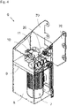
- the vehicle trailer 1 shows a schematically simplified perspective view of a vehicle trailer 1 .
- the vehicle trailer 1 includes a trailer support 2 with two supports 3, which support the vehicle trailer 1 by means of base plates 4 when the vehicle trailer 1 is not resting on a towing vehicle.
- the supports 3 are connected by means of a support winch shaft 5 . By rotating the landing gear shaft 5, the supports 3 can be moved up and down.
- the in 1 shown Vehicle trailer 1 has a crank 50 which is fixed to the support winch shaft 5 by means of a dowel pin 26 or a screw connection and allows the supports 3 to be moved manually.
- a landing gear drive 6 is shown schematically simplified in a cross-sectional view, with which the supports 3 can also be moved electrically by electrically driving the landing gear shaft 5 .
- a housing 8 protects the landing gear drive 6 from operational influences such as moisture and stone chips.
- the landing gear drive 6 is connected by means of two holders 70, of which 2 only one is visible, on a vehicle trailer 1 can be fixed.
- the landing gear drive 6 comprises an electric motor 7 as a drive, the torque of which is transmitted to a gear 10 designed as a worm gear 11 .
- the worm gear 11 has a high transmission ratio, so that the speed is reduced, for example by a fourteenth, and the torque is increased, for example by a fourteenth.
- a first interrupter 60 with a first pin 62 is mounted on the landing gear drive 6 in such a way that the base plate 4 of the support 3 depresses the first pin 62 when it has reached an upper stopping point.
- the first breaker 60 interrupts the power supply to the electric motor 7 in order to prevent the support 3 from being raised any further.
- a second interrupter 64 is shown with a second pin 66 which is arranged on the footplate 4 and interrupts the power supply to the electric motor 7 when the footplate 4 touches the ground.
- the second interrupter 66 can be bypassed by means of a button 74 arranged on the housing 8, for example in order to raise the vehicle trailer 1 far enough that the vehicle trailer 1 can be detached from a towing vehicle.
- a third interrupter 68 with a third pin 69 is arranged in front of a kingpin 90 of the vehicle trailer 1 in the direction of travel of the vehicle trailer 1 or the tractor, as shown in FIG 11 shown schematically.
- the third pin 69 is pushed in by a fifth wheel plate 94 of the towing vehicle as long as the kingpin 90 is inserted into a coupling 92 of a fifth wheel plate of the towing vehicle. If the vehicle trailer 1 is raised by extending the supports 3 so far that the third pin 69 of the saddle plate 94 is no longer pressed in, the power supply to the electric motor 7 is interrupted and the lifting of the vehicle trailer 1 is stopped.
- the alternative variant using the third circuit breaker 68 is particularly useful for new vehicle trailers 1, since retrofitting is very expensive.
- the landing gear drive 6 is shown in additional views.
- 3 shows the back of the landing gear drive 6 with the two holders 70 for fixing to the vehicle trailer 1.
- the wing-like shape of the holder 70 is shown in the perspective view in FIG 4 visible.
- the base plate 9, which has the electric motor 7 on the bottom and the gear 10 on the top, is also in 4 shown.
- FIG. 5 shows a schematic sectional view of the worm gear 11.
- the worm gear 11 transmits its torque by means of a coupling element 30 in the form of a feather key 31 to the shaft attachment 20, which is placed on the support winch shaft 5 of the vehicle trailer 1 and fixed by means of a dowel pin 26.
- the shaft attachment 20 extends along the longitudinal axial direction 82.
- the feather key 31 is fixed in the radial direction 80 on the shaft attachment 20 and held in the circumferential direction 84 by positive locking in the shaft attachment 20.
- a crank 50 slides onto the outer end 22 of the shaft attachment to change from electric operation to manual operation.
- FIG. 6 shows an enlarged view of a detail from figure 5 . It shows that the feather key 31 is coupled to the shaft attachment 20 in the radial direction 80 by means of two spring elements 32 .
- the feather key 31 comprises a first component 34 and a second component 38 which are fixed to one another in the radial direction by means of screws. In the circumferential direction 84 the second component 38 of the feather key 31 rests in a groove 24 of the shaft attachment 20 .
- the crank 50 is not attached to the outer end 22, the feather key 31 is pressed radially outwards by the spring elements 32, so that it fits into a groove 13 of a gear hub 12 of the worm gear 11 is applied and in this way a mechanical connection between the worm gear 11 and the shaft attachment 20 is produced.
- the first component 34 has a ramp 36 at its outer end, which is also the outer end 35 of the feather key 31. The ramp-like shape ensures that the feather key 31 is pressed inwards when the crank 50 is attached.
- Figures 7 and 8 show the same view with attached crank 50.
- the key 31 is pressed inwards by the crank 50, so that the key 31 moves out of the groove 13 of the gear hub 12 and in this way the mechanical connection between the worm gear 11 and the shaft attachment 20 is released .
- This allows the landing gear drive 6 to be operated manually without having to work against the self-locking of the worm gear.
- the shaft attachment 20 in a schematically simplified perspective view. In this view it can be seen how the feather key 31 is arranged in the groove 24 of the shaft attachment 20 .
- the shaft attachment 20 comprises a first cylindrical section, on which the feather key 31 is arranged, and a second section in the form of a hollow cylinder, which accommodates the landing gear shaft 5 .
- the second section includes a bore 28 in order to mount the shaft attachment on the landing gear shaft 5 in a rotationally secured manner by means of a dowel pin 26 .
Landscapes
- Engineering & Computer Science (AREA)
- Mechanical Engineering (AREA)
- Transportation (AREA)
- Vehicle Cleaning, Maintenance, Repair, Refitting, And Outriggers (AREA)
Applications Claiming Priority (1)
| Application Number | Priority Date | Filing Date | Title |
|---|---|---|---|
| DE102021115130.9A DE102021115130B3 (de) | 2021-06-11 | 2021-06-11 | Stützwindenantrieb für einen Fahrzeuganhänger, Anhängerabstützung für einen Fahrzeuganhänger, Fahrzeuganhänger und Verfahren zum Nachrüsten eines Stützwindenantriebs an einen Fahrzeuganhänger |
Publications (4)
| Publication Number | Publication Date |
|---|---|
| EP4101706A2 true EP4101706A2 (fr) | 2022-12-14 |
| EP4101706A3 EP4101706A3 (fr) | 2023-02-22 |
| EP4101706B1 EP4101706B1 (fr) | 2024-10-02 |
| EP4101706C0 EP4101706C0 (fr) | 2024-10-02 |
Family
ID=80112918
Family Applications (1)
| Application Number | Title | Priority Date | Filing Date |
|---|---|---|---|
| EP22175505.1A Active EP4101706B1 (fr) | 2021-06-11 | 2022-05-25 | Entraînement de pied d'appui pour une remorque de véhicule, support de remorque pour une remorque de véhicule et remorque de véhicule |
Country Status (2)
| Country | Link |
|---|---|
| EP (1) | EP4101706B1 (fr) |
| DE (1) | DE102021115130B3 (fr) |
Families Citing this family (1)
| Publication number | Priority date | Publication date | Assignee | Title |
|---|---|---|---|---|
| CA3116250A1 (fr) * | 2020-07-28 | 2022-01-28 | Ty-Crop Manufacturing Ltd. | Support pour remorques d'equipement |
Citations (2)
| Publication number | Priority date | Publication date | Assignee | Title |
|---|---|---|---|---|
| EP0529544B1 (fr) | 1991-08-22 | 1997-01-22 | ROCKINGER Spezialfabrik für Anhängerkupplungen GmbH & Co. | Semi-remorque avec dispositif de support actionné par un moteur |
| EP1159171B1 (fr) | 1999-03-04 | 2008-05-07 | Razor International Pty Limited | Systeme de bequille electrique de levage |
Family Cites Families (7)
| Publication number | Priority date | Publication date | Assignee | Title |
|---|---|---|---|---|
| DE20022921U1 (de) * | 2000-04-07 | 2002-10-10 | Weber-Getriebe GmbH, 48282 Emsdetten | Elektro-Stützenantrieb für Wohnwagen und Wohnmobile, mit Not-Handkurbelbetrieb |
| DE10017495C2 (de) | 2000-04-07 | 2003-02-27 | Weber Getriebe Gmbh | Elektro-Stützenantriebseinheit für Wohnwagen und Wohnmobile, mit Not-Handkurbelbetrieb |
| US20040080125A1 (en) * | 2002-10-25 | 2004-04-29 | Bird Norman A. | Motorized lift for trailer dolly |
| DE20307381U1 (de) | 2003-05-12 | 2003-08-28 | Riedl, Reinhold, Dipl.-Ing., 63897 Miltenberg | Höhenverstellbare Stütze für Sattelauflieger o.dgl. |
| EP3107770B2 (fr) * | 2014-02-12 | 2023-08-23 | Jost International Corp. | Train d'atterrissage motorisé |
| DE202014105297U1 (de) | 2014-11-05 | 2015-01-09 | Vita-Consult Dr. Dr. Med. Müller E.K. | Stütze mit ausfahrbarer Stützplatte oder Stützrad für ein Kraftfahrzeug oder einen Anhänger |
| DE102017128586B4 (de) | 2017-12-01 | 2020-08-13 | Gerhard Becskei | Deichsel mit elektrisch höhenverstellbarem Stützrad |
-
2021
- 2021-06-11 DE DE102021115130.9A patent/DE102021115130B3/de active Active
-
2022
- 2022-05-25 EP EP22175505.1A patent/EP4101706B1/fr active Active
Patent Citations (2)
| Publication number | Priority date | Publication date | Assignee | Title |
|---|---|---|---|---|
| EP0529544B1 (fr) | 1991-08-22 | 1997-01-22 | ROCKINGER Spezialfabrik für Anhängerkupplungen GmbH & Co. | Semi-remorque avec dispositif de support actionné par un moteur |
| EP1159171B1 (fr) | 1999-03-04 | 2008-05-07 | Razor International Pty Limited | Systeme de bequille electrique de levage |
Also Published As
| Publication number | Publication date |
|---|---|
| DE102021115130B3 (de) | 2022-02-24 |
| EP4101706B1 (fr) | 2024-10-02 |
| EP4101706A3 (fr) | 2023-02-22 |
| EP4101706C0 (fr) | 2024-10-02 |
Similar Documents
| Publication | Publication Date | Title |
|---|---|---|
| EP1583680B1 (fr) | Colonne de direction pour vehicule automobile | |
| DE102017200888B4 (de) | Elektrisch verstellbare Lenksäule für ein Kraftfahrzeug | |
| EP2669156B1 (fr) | Entraînement de rangement pour remorque avec une disposition coaxiale des composants de l'entraînement | |
| DE19711535A1 (de) | Motorisch verstellbare Anhängerkupplung für Kraftfahrzeuge | |
| EP3873790A1 (fr) | Système de direction à recirculation de billes | |
| EP3434934A1 (fr) | Dispositif d'entraînement de broche | |
| DE102012013970A1 (de) | Vorrichtung zum Andrücken einer Zahnstange an ein Ritzel | |
| DE102011003086A1 (de) | Zahnstangenlenkgetriebe und damit ausgestattete Servolenkung | |
| EP2248708A2 (fr) | Essieu de véhicule orientable | |
| EP3956201B1 (fr) | Système de direction à commande par câble pour un véhicule automobile doté d'un entraînement concentrique | |
| DE10328651A1 (de) | Antriebseinheit mit einem Drehschemel, einem Fahrmotor und einem Lenkmotor | |
| DE102021115130B3 (de) | Stützwindenantrieb für einen Fahrzeuganhänger, Anhängerabstützung für einen Fahrzeuganhänger, Fahrzeuganhänger und Verfahren zum Nachrüsten eines Stützwindenantriebs an einen Fahrzeuganhänger | |
| DE102009038285B4 (de) | Lenksäulenbaueinheit für ein Kraftfahrzeug | |
| WO2024032840A1 (fr) | Unité de fonctionnement réglable longitudinalement et système de direction par câble | |
| DE102019115542A1 (de) | Wartungsfähiger aggregat-riemenantrieb | |
| EP2222498B1 (fr) | Entraînement de réglage à broche filetée | |
| EP3523160B1 (fr) | Agencement de transmission pour mécanisme d'entraînement de broche, entraînement de broche et siège de véhicule | |
| DE102019201544A1 (de) | Verstellbare Lenksäule für ein Kraftfahrzeug | |
| DE19811784A1 (de) | Elektrische Lenkhilfe | |
| DE102012013964A1 (de) | Vorrichtung zum Andrücken einer Zahnstange an ein Ritzel | |
| DE102019218938A1 (de) | Verstellbare Lenksäule für ein Kraftfahrzeug | |
| DE102019212259A1 (de) | Lenksäulenanordnung für ein Kraftfahrzeug | |
| DE102019212255A1 (de) | Lenksäule für ein Steer-by-Wire Lenksystem eines Kraftfahrzeugs und Lenksäulenanordnung | |
| DE102020110611B3 (de) | Getriebe für ein zumindest teilweise elektrisch betriebenes Fahrzeug | |
| DE102013008688B4 (de) | Lenksäulenmodul für eine Lenksäule eines Kraftfahrzeugs, Kraftfahrzeug und Verfahren zur Montage eines Lenkrads |
Legal Events
| Date | Code | Title | Description |
|---|---|---|---|
| PUAI | Public reference made under article 153(3) epc to a published international application that has entered the european phase |
Free format text: ORIGINAL CODE: 0009012 |
|
| STAA | Information on the status of an ep patent application or granted ep patent |
Free format text: STATUS: THE APPLICATION HAS BEEN PUBLISHED |
|
| AK | Designated contracting states |
Kind code of ref document: A2 Designated state(s): AL AT BE BG CH CY CZ DE DK EE ES FI FR GB GR HR HU IE IS IT LI LT LU LV MC MK MT NL NO PL PT RO RS SE SI SK SM TR |
|
| PUAL | Search report despatched |
Free format text: ORIGINAL CODE: 0009013 |
|
| AK | Designated contracting states |
Kind code of ref document: A3 Designated state(s): AL AT BE BG CH CY CZ DE DK EE ES FI FR GB GR HR HU IE IS IT LI LT LU LV MC MK MT NL NO PL PT RO RS SE SI SK SM TR |
|
| RIC1 | Information provided on ipc code assigned before grant |
Ipc: B60D 1/66 20060101ALI20230118BHEP Ipc: B60S 9/08 20060101AFI20230118BHEP |
|
| STAA | Information on the status of an ep patent application or granted ep patent |
Free format text: STATUS: REQUEST FOR EXAMINATION WAS MADE |
|
| 17P | Request for examination filed |
Effective date: 20230530 |
|
| RBV | Designated contracting states (corrected) |
Designated state(s): AL AT BE BG CH CY CZ DE DK EE ES FI FR GB GR HR HU IE IS IT LI LT LU LV MC MK MT NL NO PL PT RO RS SE SI SK SM TR |
|
| GRAP | Despatch of communication of intention to grant a patent |
Free format text: ORIGINAL CODE: EPIDOSNIGR1 |
|
| STAA | Information on the status of an ep patent application or granted ep patent |
Free format text: STATUS: GRANT OF PATENT IS INTENDED |
|
| RIC1 | Information provided on ipc code assigned before grant |
Ipc: B60D 1/66 20060101ALI20240409BHEP Ipc: B60S 9/08 20060101AFI20240409BHEP |
|
| INTG | Intention to grant announced |
Effective date: 20240513 |
|
| GRAS | Grant fee paid |
Free format text: ORIGINAL CODE: EPIDOSNIGR3 |
|
| GRAA | (expected) grant |
Free format text: ORIGINAL CODE: 0009210 |
|
| STAA | Information on the status of an ep patent application or granted ep patent |
Free format text: STATUS: THE PATENT HAS BEEN GRANTED |
|
| AK | Designated contracting states |
Kind code of ref document: B1 Designated state(s): AL AT BE BG CH CY CZ DE DK EE ES FI FR GB GR HR HU IE IS IT LI LT LU LV MC MK MT NL NO PL PT RO RS SE SI SK SM TR |
|
| REG | Reference to a national code |
Ref country code: GB Ref legal event code: FG4D Free format text: NOT ENGLISH |
|
| REG | Reference to a national code |
Ref country code: CH Ref legal event code: EP |
|
| REG | Reference to a national code |
Ref country code: DE Ref legal event code: R096 Ref document number: 502022001783 Country of ref document: DE |
|
| REG | Reference to a national code |
Ref country code: IE Ref legal event code: FG4D Free format text: LANGUAGE OF EP DOCUMENT: GERMAN |
|
| U01 | Request for unitary effect filed |
Effective date: 20241017 |
|
| U07 | Unitary effect registered |
Designated state(s): AT BE BG DE DK EE FI FR IT LT LU LV MT NL PT RO SE SI Effective date: 20241104 |
|
| PG25 | Lapsed in a contracting state [announced via postgrant information from national office to epo] |
Ref country code: HR Free format text: LAPSE BECAUSE OF FAILURE TO SUBMIT A TRANSLATION OF THE DESCRIPTION OR TO PAY THE FEE WITHIN THE PRESCRIBED TIME-LIMIT Effective date: 20241002 Ref country code: IS Free format text: LAPSE BECAUSE OF FAILURE TO SUBMIT A TRANSLATION OF THE DESCRIPTION OR TO PAY THE FEE WITHIN THE PRESCRIBED TIME-LIMIT Effective date: 20250202 |
|
| PG25 | Lapsed in a contracting state [announced via postgrant information from national office to epo] |
Ref country code: ES Free format text: LAPSE BECAUSE OF FAILURE TO SUBMIT A TRANSLATION OF THE DESCRIPTION OR TO PAY THE FEE WITHIN THE PRESCRIBED TIME-LIMIT Effective date: 20241002 |
|
| PG25 | Lapsed in a contracting state [announced via postgrant information from national office to epo] |
Ref country code: NO Free format text: LAPSE BECAUSE OF FAILURE TO SUBMIT A TRANSLATION OF THE DESCRIPTION OR TO PAY THE FEE WITHIN THE PRESCRIBED TIME-LIMIT Effective date: 20250102 |
|
| PG25 | Lapsed in a contracting state [announced via postgrant information from national office to epo] |
Ref country code: GR Free format text: LAPSE BECAUSE OF FAILURE TO SUBMIT A TRANSLATION OF THE DESCRIPTION OR TO PAY THE FEE WITHIN THE PRESCRIBED TIME-LIMIT Effective date: 20250103 |
|
| PG25 | Lapsed in a contracting state [announced via postgrant information from national office to epo] |
Ref country code: PL Free format text: LAPSE BECAUSE OF FAILURE TO SUBMIT A TRANSLATION OF THE DESCRIPTION OR TO PAY THE FEE WITHIN THE PRESCRIBED TIME-LIMIT Effective date: 20241002 Ref country code: CZ Free format text: LAPSE BECAUSE OF FAILURE TO SUBMIT A TRANSLATION OF THE DESCRIPTION OR TO PAY THE FEE WITHIN THE PRESCRIBED TIME-LIMIT Effective date: 20241002 |
|
| PG25 | Lapsed in a contracting state [announced via postgrant information from national office to epo] |
Ref country code: RS Free format text: LAPSE BECAUSE OF FAILURE TO SUBMIT A TRANSLATION OF THE DESCRIPTION OR TO PAY THE FEE WITHIN THE PRESCRIBED TIME-LIMIT Effective date: 20250102 |
|
| U20 | Renewal fee for the european patent with unitary effect paid |
Year of fee payment: 4 Effective date: 20250516 |
|
| PG25 | Lapsed in a contracting state [announced via postgrant information from national office to epo] |
Ref country code: SM Free format text: LAPSE BECAUSE OF FAILURE TO SUBMIT A TRANSLATION OF THE DESCRIPTION OR TO PAY THE FEE WITHIN THE PRESCRIBED TIME-LIMIT Effective date: 20241002 |
|
| PG25 | Lapsed in a contracting state [announced via postgrant information from national office to epo] |
Ref country code: SK Free format text: LAPSE BECAUSE OF FAILURE TO SUBMIT A TRANSLATION OF THE DESCRIPTION OR TO PAY THE FEE WITHIN THE PRESCRIBED TIME-LIMIT Effective date: 20241002 |
|
| PLBE | No opposition filed within time limit |
Free format text: ORIGINAL CODE: 0009261 |
|
| STAA | Information on the status of an ep patent application or granted ep patent |
Free format text: STATUS: NO OPPOSITION FILED WITHIN TIME LIMIT |
|
| 26N | No opposition filed |
Effective date: 20250703 |
|
| REG | Reference to a national code |
Ref country code: CH Ref legal event code: H13 Free format text: ST27 STATUS EVENT CODE: U-0-0-H10-H13 (AS PROVIDED BY THE NATIONAL OFFICE) Effective date: 20251223 |
|
| PG25 | Lapsed in a contracting state [announced via postgrant information from national office to epo] |
Ref country code: CH Free format text: LAPSE BECAUSE OF NON-PAYMENT OF DUE FEES Effective date: 20250531 |
|
| PG25 | Lapsed in a contracting state [announced via postgrant information from national office to epo] |
Ref country code: MC Free format text: LAPSE BECAUSE OF FAILURE TO SUBMIT A TRANSLATION OF THE DESCRIPTION OR TO PAY THE FEE WITHIN THE PRESCRIBED TIME-LIMIT Effective date: 20241002 |
|
| PG25 | Lapsed in a contracting state [announced via postgrant information from national office to epo] |
Ref country code: IE Free format text: LAPSE BECAUSE OF NON-PAYMENT OF DUE FEES Effective date: 20250525 |