EP4101954A1 - Boîte à filer pour un dispositif de filature à rotor à bouts ouverts - Google Patents
Boîte à filer pour un dispositif de filature à rotor à bouts ouverts Download PDFInfo
- Publication number
- EP4101954A1 EP4101954A1 EP22176977.1A EP22176977A EP4101954A1 EP 4101954 A1 EP4101954 A1 EP 4101954A1 EP 22176977 A EP22176977 A EP 22176977A EP 4101954 A1 EP4101954 A1 EP 4101954A1
- Authority
- EP
- European Patent Office
- Prior art keywords
- thread
- spinning
- opening
- spinning box
- box
- Prior art date
- Legal status (The legal status is an assumption and is not a legal conclusion. Google has not performed a legal analysis and makes no representation as to the accuracy of the status listed.)
- Granted
Links
Images



Classifications
-
- D—TEXTILES; PAPER
- D01—NATURAL OR MAN-MADE THREADS OR FIBRES; SPINNING
- D01H—SPINNING OR TWISTING
- D01H1/00—Spinning or twisting machines in which the product is wound-up continuously
- D01H1/14—Details
- D01H1/16—Framework; Casings; Coverings ; Removal of heat; Means for generating overpressure of air against infiltration of dust; Ducts for electric cables
-
- D—TEXTILES; PAPER
- D01—NATURAL OR MAN-MADE THREADS OR FIBRES; SPINNING
- D01H—SPINNING OR TWISTING
- D01H4/00—Open-end spinning machines or arrangements for imparting twist to independently moving fibres separated from slivers; Piecing arrangements therefor; Covering endless core threads with fibres by open-end spinning techniques
- D01H4/04—Open-end spinning machines or arrangements for imparting twist to independently moving fibres separated from slivers; Piecing arrangements therefor; Covering endless core threads with fibres by open-end spinning techniques imparting twist by contact of fibres with a running surface
- D01H4/08—Rotor spinning, i.e. the running surface being provided by a rotor
-
- D—TEXTILES; PAPER
- D01—NATURAL OR MAN-MADE THREADS OR FIBRES; SPINNING
- D01H—SPINNING OR TWISTING
- D01H4/00—Open-end spinning machines or arrangements for imparting twist to independently moving fibres separated from slivers; Piecing arrangements therefor; Covering endless core threads with fibres by open-end spinning techniques
- D01H4/48—Piecing arrangements; Control therefor
- D01H4/50—Piecing arrangements; Control therefor for rotor spinning
Definitions
- the present invention relates to a spinning box for an open-end rotor spinning device, in particular for a semi-automatic rotor spinning device, the spinning box having a sliver inlet for feeding a fiber structure to an opening unit, which can be arranged in a opening unit receptacle of the spinning box, and a thread outlet opening through which a supplied fiber bundle generated spun thread can be discharged from the spin box.
- Such a spinning box is, for example, from the document EP 2 963 164 A1 known.
- Spinning boxes are commonly used to protect the components necessary for the production of a filament from the environment.
- Known spinning boxes house an opening unit, by means of which a supplied fiber structure is separated into individual fibers and parallelized. The separated fibers are guided via a fiber guide channel leading from the opening unit to a spinning rotor arranged in the spinning box on its fiber chute wall. The rotation of the spinning rotor ensures that the individually supplied fibers slide from the fiber sliding wall into a radial fiber groove of the spinning rotor, in which the individual fibers attach themselves to an open end of a spun thread end deposited in the fiber groove.
- the spun thread is drawn off from the spinning box via a thread draw-off channel communicating with the spinning rotor cup, as a result of which the spun thread is further developed in the course of continuous tacking so that it can be drawn off.
- a piecing process is required to resume the spinning process, in which a spinning thread end coming from the package bobbin must be fed into the thread withdrawal channel and fed to the spinning rotor.
- the end of the spinning thread must be separated and prepared by unraveling or twisting the end of the spinning thread so that the individual fibers can attach more reliably to the open end of the spinning thread.
- the spinning rotor For this purpose it is usual to prepare the end of the spinning thread by means of a service unit or inside the spinning box by means of the spinning rotor, as for example from the document EP 3 276 057 A1 known to do.
- the former is advantageous for automatic open-end spinning machines, but unsuitable for semi-automatic open-end spinning machines that do not have a service unit.
- the latter solution is suitable for this.
- the spinning rotor must also be driven in a defined manner, which can lead to a shortening of the service life of the spinning rotor drive for pure spinning thread production.
- the present invention is intended to provide an alternative possibility by means of which a preparation of a spun yarn end for a piecing process is made possible, in particular protected from the ambient air and also suitable in particular for semi-automatic open-end spinning machines.
- a spinning box is proposed with a fiber sliver input for feeding a fiber structure to an opening unit, which can be arranged in a opening unit receptacle of the spinning box, and with a thread exit opening through which a spinning thread produced from the supplied fiber structure can be discharged from the spinning box.
- the spinning box according to the present invention is characterized in that the spinning box is designed to accommodate a yarn end preparation unit for preparing a spun yarn end, the yarn end preparation unit being locatable opposite to the yarn exit opening for mutual transfer of a spun yarn.
- thread end preparation protected from the ambient air can be carried out within the spinning box, in particular independently of a service unit and furthermore in particular without detriment to the service life of a spinning rotor drive.
- Such a spinning box is particularly suitable for a semi-automatic open-end spinning machine, but can also be used in automatic open-end spinning machines.
- the spinning box has a thread insertion recess which communicates with the thread exit opening and can be operatively connected to the thread end preparation unit, into which a spun thread can be transferred from the thread exit opening, with the thread insertion recess extending in a defined direction away from the thread exit opening, starting from the thread exit opening.
- the thread insertion recess thus increases the degree of freedom in the design of the spin box.
- the yarn end preparation unit can be arranged as required within the spinning box at a selected location, taking into account the space available.
- the spinning box preferably comprises a first side of the housing and a second side of the housing, which adjoins the first side of the housing at an angle of less than 180°, with the thread outlet opening being formed in the first side of the housing and with the thread insertion recess extending from the thread outlet opening into the second side of the housing extends and is in particular at least partially slit-like.
- the spinning box has a third side of the housing, which adjoins the second side of the housing at an angle of less than 180°, with the thread insertion recess extending from the thread outlet opening into the third side of the housing and in particular being at least partially embodied as a slot.
- the first and second and, in particular, the third, housing side are formed by an attachment that can be removably attached to the spin box.
- the attachment can be done via conventional clamp, snap, screw connections or similar positive and / or non-positive connection types, which allow a non-destructive, repeatable removal of the attachment.
- Such an attachment favors the reliable transfer of the spun thread from the thread exit opening into the thread insertion recess as well as accessibility to the thread end preparation unit, for example in order to rectify faults or replace wearing parts.
- the attachment forms at least one last component of the spin box in the withdrawal direction of the spinning thread or more preferably the last component of the spin box, which furthermore preferably forms a component that is raised or protrudes from the other sides of the housing of the spin box.
- the housing sides of the attachment mounted on the spin box are preferably aligned on the outside surface side with the surface sides of the spin box adjoining these housing sides. Furthermore, a front surface side of the spinning box adjacent to the sliver inlet is preferably formed at least largely or completely from at least one housing side of the attachment.
- the thread end preparation unit preferably has a thread cutting unit, for example a thread cutting unit, which is arranged in the spinning box opposite the thread insertion recess for cutting a spun thread received in the thread insertion recess.
- the thread cutting unit can thus be offside of the normal running path of the spun thread, which means that a disruption to the spinning process can be reliably avoided in the event of a possible defect in the thread cutting unit.
- a thread guide ramp is preferably arranged within the spinning box, which is assigned to the thread insertion recess in such a way that a spun thread inserted into the thread insertion recess can be guided in a defined manner via the thread guide ramp.
- the thread guide ramp is particularly preferably arranged between the thread withdrawal channel outlet and the thread cutting unit, with the thread guide ramp protruding beyond the thread withdrawal channel outlet along the withdrawal direction of the spun thread, more preferably with a ramp surface extending transversely to the thread withdrawal channel outlet and leading away from it, in order to reliably guide the spun thread into or to a spun thread separating location of the separation unit in the course of loading.
- the thread cutting unit can be formed in particular by the thread cutting unit having two blade elements that can be moved relative to one another, the blade elements forming a cutting opening for cutting the spun thread.
- the thread guide ramp is more preferably designed and arranged corresponding to a cutting edge of one of the blade elements, whereby the spun thread is reliably guided into the cutting opening, preferably to the cutting base of the cutting opening, in the course of insertion, in order to enable reliable cutting of the spun thread.
- a thread sensor is assigned to the thread insertion recess in the spinning box for detecting a spun thread accommodated in the thread insertion recess. More preferably, the thread separating unit can be controlled based on a detection signal of the thread sensor by this or an interposed control unit for separating the spun thread laid in the thread insertion recess. In this way, a separation of the spinning thread can be initialized automatically.
- the spin box has a cleaning housing, which has a discharge channel that extends along the opening unit receptacle and has an inlet opening that leads to an outside surrounding the spin box is open, with an outlet opening which can be coupled to a dirt channel of the spinning machine, and with a receiving opening which is arranged between the inlet and outlet opening and which is designed to be open to the opening for the opening of the opening unit in order to remove dirt particles from the opening for the opening unit, the cleaning housing being away from the opening has a feed opening leading into the discharge channel for feeding in dirt particles and fiber residues.
- the feed opening enables the cleaning housing, in particular the discharge channel, to be used to discharge dirt particles from areas of the spin box other than the opening unit receptacle.
- the cleaning case is as per the document EP 2 963 164 A1 previously known, intended to discharge the dirt particles and fiber residues released in the course of the separation of the supplied fiber structure into a dirt channel of the open-end spinning machine.
- negative pressure is applied to the discharge channel, with the inlet opening communicating with the ambient air ensuring that there is no constant increase in negative pressure within the opening unit receptacle.
- this leads to a continuous flow of air in the discharge channel, which is directed from the inlet opening in the direction of the outlet opening, as a result of which dirt particles and fiber residues can be entrained from the opening unit receptacle via the intermediate receptacle opening.
- the yarn end preparation unit has a yarn end opening unit for opening a spun yarn end inserted into the yarn outlet opening, the yarn end opening unit being formed by a yarn withdrawal channel that can be operatively connected to a spinning rotor and has a yarn withdrawal channel outlet, which is arranged in the spinning box opposite the yarn outlet opening.
- the discharge opening is formed in the thread draw-off channel in front of the thread-end opening unit in the drawing-off direction of the spun thread.
- the feed opening is preferably arranged between the inlet opening and the receiving opening, in particular close to the inlet opening, more preferably immediately downstream of the inlet opening. This makes it easier to access the feed opening, for example for cleaning purposes.
- the feed opening is also preferably formed by an insert which is arranged in the discharge channel, in particular in an exchangeable manner.
- the cleaning of the feed opening can thus be carried out in a further simplified manner.
- the feed opening can be adapted to different fiber materials that can be processed by the open-end spinning machine or in the spinning box.
- the spinning box is part of a spinning device of an open-end spinning machine, in particular a semi-automatic rotor spinning machine.
- the spinning device comprises a spinning rotor that can be driven, preferably individually, the spinning rotor cup of which rotates at high speed during spinning in a rotor housing that can be subjected to negative pressure.
- the rotor housing can be closed by a cover element, which is formed by the spin box.
- the opening unit receptacle there is an opening unit, in particular an opening roller, to which a sliver can be fed via the sliver input.
- the opening roller is arranged and designed to break up the fiber structure into individual fibers, dirt particles and/or fiber residues detached from the fiber structure being discharged via the cleaning housing into a dirt channel of the spinning machine.
- a fiber guide channel arranged in the spinning box is operatively connected to the opening roller, via which the opened fibers can be fed to the spinning rotor cup.
- a thread withdrawal channel entrance is arranged opposite the spinning rotor cup, the thread withdrawal channel extending from the thread withdrawal channel entrance to a thread withdrawal channel exit opposite the thread outlet opening within the spinning box.
- the spinning device makes it possible to prepare a spinning thread end in the course of a piecing process, which can be carried out completely inside the spinning box and protected from the ambient air.
- a method for piecing a spun yarn in an open-end spinning machine in particular a semi-automatic rotor spinning machine, is proposed, the open-end spinning machine having a spinning device as described above.
- a through the thread outlet opening continuous spun thread from the thread outlet opening in the Thread insertion recess transferred in one step, a through the thread outlet opening continuous spun thread from the thread outlet opening in the Thread insertion recess transferred.
- the transfer can be carried out manually by an operator or automatically, for example by means of a thread clamping unit which is designed to be movable outside the spinning box relative to the thread travel path of the spun thread.
- the thread clamping unit can be assigned to a service unit serving the spinning device or to a spinning station comprising the spinning device or to the spinning device.
- the thread cutting unit is initialized to separate the inserted spinning thread.
- the initialization can preferably take place by means of a thread sensor monitoring the thread insertion recess in a manner as described above by way of example.
- the initialization can take place via an action by the operator, such as triggering a thread separation signal by operating an actuating device.
- the initialization of the thread cutting unit can be triggered directly by the actuating device or with the interposition of a control unit.
- the severed filament section is preferably disposed of within the spin box via the cleaning housing in a manner as described above.
- the cut end of the spinning thread is presented to the thread exit opening for introduction into the spinning box, in particular into the thread withdrawal channel.
- a suction flow is preferably present at the thread withdrawal channel outlet, via which the spun thread end is sucked into the thread withdrawal channel.
- the suction flow can preferably be generated via the compressed air supply and/or via the negative pressure present at the discharge opening.
- the end of the spun thread introduced into the thread draw-off channel is then prepared by means of the end-of-thread preparation unit.
- the end of the spun thread is preferably loosened or twisted in the thread draw-off channel with the prevailing supply of compressed air.
- the dissolved end of the spinning thread is fed to the spinning rotor, in particular to the spinning rotor cup, for the piecing process to be continued.
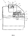
- FIGS. 1 and 2 show a spin box 1 according to an embodiment.
- Spinning box 1 has a sliver inlet, which in the illustrated embodiment is preceded in a known manner by a sliver intake comprising a precompressor 10 and a driveable feed roller 12 downstream in the sliver transport direction, via which the sliver is precompacted via the sliver inlet into spinning box 1 to form an opening unit , Not shown opening roller is transported.
- the spinning box 1 has a thread outlet opening 4 for discharging a spinning thread 2 produced by a spinning rotor covered by the spinning box 1 (not shown). starting from the thread outlet opening 4 in a direction leading away therefrom, the thread insertion recess 8 extends like a slit.
- the thread outlet opening 4 and the thread insertion recess 8 are formed in an attachment 6 which is attached to the spinning box 1 in a removable or non-destructively detachable manner via a snap-in connection.
- the attachment 6 forms a first housing side 6a and a second housing side 6b for the spinning box 1, the thread outlet opening 4 being formed on the first housing side 6a and the thread insertion recess 8 extending into the second housing side 6b.
- the first housing side 6a and the second housing side 6b are designed to adjoin one another, including an angle of less than 180°.
- figure 3 shows a further exemplary embodiment of the attachment 6, which differs from that in figure 1
- the attachment 6 shown differs only by a third housing side 6c, in which the thread insertion recess 8 extends and which is formed adjacent to the second housing side 6b, enclosing an angle of less than 180°.
- the spinning box 1 is designed to accommodate a yarn end preparation unit which is designed to prepare the spun yarn 2 , the yarn end preparation unit according to this exemplary embodiment being arranged opposite the yarn outlet opening 4 and the yarn insertion recess 8 within the spinning box 1 .
- the thread preparation unit has a thread cutting unit 20, which as a thread cutting unit with a first blade element 21 and a second blade element 22, which can be moved relative to the first blade element 21, for cutting the spun thread 2.
- the second blade element 22 is coupled to a piston which can be moved in and out.
- the thread cutting unit 20 is arranged with its cutting opening formed by the first blade element 21 and second blade element 22 parallel to a thread withdrawal channel 30 adjacent to a thread withdrawal channel outlet 32 opposite the thread insertion recess 8, with the thread withdrawal channel outlet 32 lying opposite the thread outlet opening 4.
- the yarn end preparation unit also has a yarn end opening unit, which is connected upstream of the yarn withdrawal channel outlet in the yarn withdrawal channel 30 in the withdrawal direction of the spun yarn 2 .
- the yarn end opening unit has a pneumatic connection 34, via which compressed air can be introduced in a known manner into the yarn withdrawal channel 30 counter to the withdrawal direction to generate a turbulent air flow in the yarn withdrawal channel 30 in order to dissolve a spun yarn end held in the yarn withdrawal channel 30 in the area of the yarn end preparation unit.
- the spinning box 1 has a cleaning housing 40, which in the usual way has a discharge channel 41 extending along the opening unit receptacle with an inlet opening 42 which is open to the outside surrounding the spinning box 1, an outlet opening which can be coupled to a dirt channel of the spinning machine, and a receiving opening which is arranged between the inlet opening 42 and the outlet opening and which is designed to be open to the opening for the opening of the opening for removing dirt particles from the opening for opening of the opening.
- the cleaning housing 40 comprises a supply opening leading into the discharge channel 41 for the supply of dirt particles away from the receiving opening.
- the feed opening is formed in an insert 50 which is arranged in an exchangeable manner in the bottom of an entry area of the discharge channel 40 near the entry opening 42 .
- the feed opening is coupled to a discharge opening by means of a connecting hose or channel, which is located in front of the thread end opening unit in the thread withdrawal channel 30 in the withdrawal direction.
- FIGS. 4 and 5 show a schematic perspective view of a section of a spinning box 1 with an attachment 50 according to a further embodiment.
- the spinning box 1 has a ramp-like design on the upper side, with the attachment 50 extending over the front side of the spinning box 1 adjacent to the upper side the sliver intake, not shown, comprising the pre-compressor 10 and the feed roller 12 extends in a defined manner.
- the attachment 50 extends at the front of the spinning box 1 along the withdrawal direction of the spun thread 1 from the top to a position adjacent to the sliver draw-in and in a direction orthogonal to the withdrawal direction, leading away from the sliver draw-in, for the most part over the front side, towards this Example over the complete front side of the spin box 1.
- the attachment 50 is therefore larger in its dimensions than in Figures 1 to 3 shown attachment 50 is formed, whereby the attachment 50 can be more reliably detachably fixed to the spin box 1, wherein after removing the attachment 50 from the spin box 1 there is also a larger access area into the spin box 1, which allows for easier and more reliable operation of the attachment 50 hidden components such as the thread cutting unit 20 within the spin box 1 allows.
- the attachment 50 is detachably fixed to the spinning box 1 by means of locking means.
- locking means for example, latching pawls and latching recesses 16 of complementary design on the spinning box 1 and the attachment 50 can be used as latching means.
- the attachment 50 is inserted in a recess 14 of the spin box 1, with at least the outer surface sides of the spinning box 1 being aligned on the outside with the housing sides 6a, 6b, 6c of the attachment 50, i.e. merging into one another without edges at least on the outside.
- a thread guide ramp 60 Inside the spinning box 1, between the thread withdrawal channel 30 and the thread cutting unit 20, there is a thread guide ramp 60 with a ramp surface 62 running transversely to the thread withdrawal channel outlet 32 and leading away from it, over which the spun thread 1 laid in the thread insertion recess 8 moves in the direction of the bottom of the cutting opening of the thread cutting unit 20 is conducted.
- the thread guide ramp 60 protrudes beyond the thread withdrawal channel outlet 32 in the withdrawal direction of the spun thread 2.
- the thread guide ramp 60 according to this exemplary embodiment is designed and arranged to correspond to the cutting edge of the first blade element 21, as a result of which the spun thread 2 can be reliably guided into the cutting base of the cutting opening.
- the spin box 1 is part of a spinning device of an open-end rotor spinning machine, where the spinning device comprises a spinning rotor that can be driven in a defined manner, the spinning rotor cup of which rotates at high speed during spinning in a rotor housing that can be subjected to negative pressure.
- the rotor housing can be closed by a cover element, which is formed by the spinning box 1.
- an opening roller is arranged in the opening unit receptacle, to which the fiber structure can be fed via the fiber sliver input.
- the opening roller is arranged and designed to break up the fiber structure into individual fibers, dirt particles and/or fiber residues detached from the fiber structure being discharged via the cleaning housing into a dirt channel of the spinning machine.
- a fiber guide channel arranged in the spinning box 1 is in operative connection with the opening roller, via which the opened fibers can be fed to the spinning rotor cup.
- a yarn withdrawal channel entrance is arranged opposite the spinning rotor cup, the yarn withdrawal channel 30 extending from the yarn withdrawal channel entrance to the yarn withdrawal channel outlet 32 within the spinning box 2 opposite the yarn outlet opening 4 .
- the spun yarn 2 produced is drawn off from the spinning box 1 via the yarn outlet opening 4 in a direction away from the spinning box 1 and fed to a take-up device for forming a take-up package.
- a yarn sensor for monitoring a characteristic of the running spinning yarn 2 is arranged between the spinning box 1 and the winding device. As soon as the thread sensor detects a defined deviation, there is a controlled interruption in spinning with a controlled thread cut of the spun thread 2.
- a movable thread clamping unit can be designed to clamp the exiting spun thread 2 and to transfer it from the thread outlet opening 4 into the thread insertion recess 8.
- the thread clamping unit can be assigned to a service unit serving the spinning device or to a spinning station comprising the spinning device or to the spinning device.
- the thread insertion recess 8 is assigned a further thread sensor for detecting the spinning thread 2 in the thread insertion recess 8, the further thread sensor being arranged within the spinning box 2 according to this preferred exemplary embodiment.
- the control unit initiates the cutting of the spun thread 2 via the thread cutting unit 20.
- the severed thread end section is separated by the vacuum present in the Drainage sucked into this and disposed of via the cleaning housing 40.
- the thread clamping unit submits the cut spun thread end of the thread outlet opening 4, so that the spun thread end in the Thread withdrawal channel 30 can be sucked.
- the suction flow can preferably be generated via the compressed air supply via the compressed air connection 34 and/or via the negative pressure present at the discharge opening.
- a turbulent air flow is generated via the supplied compressed air to dissolve the spun thread end. After dissolving, the spinning thread end is fed to the spinning rotor in the usual way, while maintaining the supply of compressed air and releasing the clamp, for example by releasing the thread clamping unit.
- the spun thread end in the event of a thread breakage, in which a spun thread end runs onto the package in the usual manner, can be retrieved via a return unit and introduced into the thread withdrawal channel 30 via the thread outlet opening 4 .
- the return unit can be assigned to the service unit or the spinning station with the spinning device.
- the spun thread 2 can be transferred manually or automatically from the thread exit opening 4 into the thread insertion recess 8, with the thread being cut in a manner as described above.
- the severed filament section is disposed of as described above.
- the cut end of the spinning thread is introduced manually or automatically via the thread outlet opening 4 into the thread withdrawal channel and, as also previously described, is dissolved in order to then be fed to the spinning rotor for the continuation of the piecing.
Landscapes
- Engineering & Computer Science (AREA)
- Mechanical Engineering (AREA)
- Textile Engineering (AREA)
- Spinning Or Twisting Of Yarns (AREA)
Applications Claiming Priority (1)
| Application Number | Priority Date | Filing Date | Title |
|---|---|---|---|
| CN202110647564.4A CN115467056B (zh) | 2021-06-10 | 2021-06-10 | 用于自由端转杯纺纱装置的纺纱箱 |
Publications (2)
| Publication Number | Publication Date |
|---|---|
| EP4101954A1 true EP4101954A1 (fr) | 2022-12-14 |
| EP4101954B1 EP4101954B1 (fr) | 2026-03-04 |
Family
ID=81878209
Family Applications (1)
| Application Number | Title | Priority Date | Filing Date |
|---|---|---|---|
| EP22176977.1A Active EP4101954B1 (fr) | 2021-06-10 | 2022-06-02 | Boîte à filer pour un dispositif de filature à rotor à bouts ouverts |
Country Status (2)
| Country | Link |
|---|---|
| EP (1) | EP4101954B1 (fr) |
| CN (1) | CN115467056B (fr) |
Citations (7)
| Publication number | Priority date | Publication date | Assignee | Title |
|---|---|---|---|---|
| DE3640217A1 (de) * | 1986-11-25 | 1988-05-26 | Fritz Stahlecker | Oe-rotorspinnmaschine |
| DE10224589A1 (de) * | 2001-06-23 | 2003-01-09 | Rieter Ingolstadt Spinnerei | Auflösewalzengehäuse |
| WO2005033385A1 (fr) * | 2003-09-04 | 2005-04-14 | Saurer Gmbh & Co. Kg | Dispositif de filature a bouts ouverts |
| EP2963164A1 (fr) | 2014-06-12 | 2016-01-06 | Saurer Germany GmbH & Co. KG | Métier à tisser à extrémité ouverte |
| DE102015012911A1 (de) * | 2015-10-06 | 2017-04-06 | Saurer Germany Gmbh & Co. Kg | Faserbandauflöseeinrichtung für eine Offenend-Rotorspinnvorrichtung |
| EP3153612A1 (fr) * | 2015-10-08 | 2017-04-12 | Rieter Ingolstadt GmbH | Procédé de préparation d'un penne pour commencer à filer sur un dispositif de filature à rotor d'une machine à filer à rotor et machine à filer à rotor |
| EP3276057A1 (fr) | 2016-07-28 | 2018-01-31 | Rieter Ingolstadt GmbH | Unité guide-fil, métier à tisser à extrémité ouverte et procédé de fonctionnement d'un poste de filage |
Family Cites Families (8)
| Publication number | Priority date | Publication date | Assignee | Title |
|---|---|---|---|---|
| DE2534816C3 (de) * | 1975-08-05 | 1979-12-20 | Zinser Textilmaschinen Gmbh, 7333 Ebersbach | OE-Spinnmaschine |
| CS200910B1 (en) * | 1978-04-21 | 1980-10-31 | Karel Mikulecky | Method of and apparatus for spining-in yarn in open-end rotor spinning unit |
| DE3418780A1 (de) * | 1984-05-19 | 1985-11-21 | Schubert & Salzer Maschinenfabrik Ag, 8070 Ingolstadt | Verfahren und vorrichtung zum vorbereiten eines abgelaengten fadenendes zum wiederanspinnen einer offenend-spinnvorrichtung |
| JPH10102327A (ja) * | 1996-09-25 | 1998-04-21 | Toyota Autom Loom Works Ltd | オープンエンド精紡機の糸継ぎ準備方法及び装置 |
| CZ44097A3 (cs) * | 1997-02-13 | 1998-10-14 | Rieter Elitex A.S. | Způsob individuálního zapřádání příze na pracovním místě rotorového dopřádacího stroje a zařízení k provádění tohoto způsobu |
| CZ290468B6 (cs) * | 2000-07-26 | 2002-07-17 | Rieter Cz A. S. | Způsob zapřádání příze na pracovním místě rotorového dopřádacího stroje a zařízení k jeho provádění |
| DE102012008922A1 (de) * | 2012-05-03 | 2013-11-07 | Saurer Germany Gmbh & Co. Kg | Vorrichtung zur Erzeugung eines anspinnfähigen Garnendes an einer Offenend-Spinnvorrichtung |
| DE102015016664A1 (de) * | 2015-12-19 | 2017-06-22 | Saurer Germany Gmbh & Co. Kg | Fadenspleißvorrichtung |
-
2021
- 2021-06-10 CN CN202110647564.4A patent/CN115467056B/zh active Active
-
2022
- 2022-06-02 EP EP22176977.1A patent/EP4101954B1/fr active Active
Patent Citations (7)
| Publication number | Priority date | Publication date | Assignee | Title |
|---|---|---|---|---|
| DE3640217A1 (de) * | 1986-11-25 | 1988-05-26 | Fritz Stahlecker | Oe-rotorspinnmaschine |
| DE10224589A1 (de) * | 2001-06-23 | 2003-01-09 | Rieter Ingolstadt Spinnerei | Auflösewalzengehäuse |
| WO2005033385A1 (fr) * | 2003-09-04 | 2005-04-14 | Saurer Gmbh & Co. Kg | Dispositif de filature a bouts ouverts |
| EP2963164A1 (fr) | 2014-06-12 | 2016-01-06 | Saurer Germany GmbH & Co. KG | Métier à tisser à extrémité ouverte |
| DE102015012911A1 (de) * | 2015-10-06 | 2017-04-06 | Saurer Germany Gmbh & Co. Kg | Faserbandauflöseeinrichtung für eine Offenend-Rotorspinnvorrichtung |
| EP3153612A1 (fr) * | 2015-10-08 | 2017-04-12 | Rieter Ingolstadt GmbH | Procédé de préparation d'un penne pour commencer à filer sur un dispositif de filature à rotor d'une machine à filer à rotor et machine à filer à rotor |
| EP3276057A1 (fr) | 2016-07-28 | 2018-01-31 | Rieter Ingolstadt GmbH | Unité guide-fil, métier à tisser à extrémité ouverte et procédé de fonctionnement d'un poste de filage |
Also Published As
| Publication number | Publication date |
|---|---|
| CN115467056B (zh) | 2023-10-27 |
| EP4101954B1 (fr) | 2026-03-04 |
| CN115467056A (zh) | 2022-12-13 |
Similar Documents
| Publication | Publication Date | Title |
|---|---|---|
| EP3652368B1 (fr) | Procédé pour faire fonctionner un arrangement de filage à jet d'air | |
| EP0226582B1 (fr) | Procede et dispositif pour joindre les fils sur un systeme de filature a fibre liberee | |
| EP0296546A1 (fr) | Métier à filer pour la production de fils d'un ruban de fibres discontinues | |
| CH656646A5 (de) | Verfahren zum garnanspinnen beim wiederingangsetzen einer offenend-rotorspinneinheit und eine solche einheit zur durchfuehrung des verfahrens. | |
| DE102012110926B4 (de) | Verfahren zur Vorbereitung eines Garnendes zum Anspinnen an einer Rotorspinnmaschine und einem Spinnrotor | |
| EP0162367B2 (fr) | Procédé et dispositif pour la préparation de l'extrémité de fil pour la remise en route d'une machine à bout libéré | |
| DE19610960A1 (de) | Verfahren zum Offenend-Spinnen | |
| DE102017107424A1 (de) | Vorrichtung und Verfahren zum Ansaugen, Zwischenspeichern und Abführen eines Fadens sowie Textilmaschine | |
| EP4101954A1 (fr) | Boîte à filer pour un dispositif de filature à rotor à bouts ouverts | |
| EP3839114B1 (fr) | Procédé d'agencement d'une bande de fibre sur une unité de filage d'un métier à filer | |
| EP2660376A1 (fr) | Dispositif de fabrication d'une penne permettant la rattache sur un dispositif de tissage à extrémité ouverte | |
| DE3103326C2 (de) | Garnanspinnvorrichtung an einer Offenend-Rotorspinneinheit | |
| DE3607206A1 (de) | Verfahren und vorrichtung zum herstellen einer spleissverbindung | |
| DE2915788A1 (de) | Anspinnverfahren an einer offenend- rotorspinneinheit und vorrichtung zum durchfuehren dieses verfahrens | |
| EP1660708B1 (fr) | Plaque a rainure-guide pour un dispositif de filature a rotor a bout libere | |
| EP0049857B1 (fr) | Métier à tricoter circulaire pour fabriquer un tricot pelucheux ayant des fibres insérées | |
| DE3410471A1 (de) | Oe-friktionsspinnmaschine mit einer vielzahl von spinnaggregaten und einem verfahrbaren wartungsgeraet | |
| EP0319939B1 (fr) | Procédé et manipulateur pour guider les fils en déplacement | |
| EP4208592A1 (fr) | Procédé pour exécuter un processus de changement de pot de filature automatique au niveau d'un poste de filature d'un métier à filer, métier à filer, et dispositif de changement de pot de filature déplaçable | |
| EP4413187B1 (fr) | Dispositif de filage, métier à filer à rotor, et procédé pour empêcher l'accumulation de fibres dans un dispositif de filage | |
| EP1295974A2 (fr) | Métier à filer à jet d'air avec un dispositif défibreur | |
| EP4050138B1 (fr) | Procédé de fonctionnement d'un poste de travail d'un métier à filer et poste de travail | |
| CH623854A5 (en) | Method and apparatus for the pneumatic elimination of fibre slivers from an open-end spinning rotor after an interruption of the spinning process. | |
| CH690009A5 (de) | Verfahren zum Anspinnen des Garnes an Offen-End-Spinnmaschinen und Vorrichtung zur Ausführung des Verfahrens. | |
| DE3908463A1 (de) | Vorrichtung zum zwischenspeichern eines doppelfadens |
Legal Events
| Date | Code | Title | Description |
|---|---|---|---|
| PUAI | Public reference made under article 153(3) epc to a published international application that has entered the european phase |
Free format text: ORIGINAL CODE: 0009012 |
|
| STAA | Information on the status of an ep patent application or granted ep patent |
Free format text: STATUS: THE APPLICATION HAS BEEN PUBLISHED |
|
| AK | Designated contracting states |
Kind code of ref document: A1 Designated state(s): AL AT BE BG CH CY CZ DE DK EE ES FI FR GB GR HR HU IE IS IT LI LT LU LV MC MK MT NL NO PL PT RO RS SE SI SK SM TR |
|
| STAA | Information on the status of an ep patent application or granted ep patent |
Free format text: STATUS: REQUEST FOR EXAMINATION WAS MADE |
|
| 17P | Request for examination filed |
Effective date: 20230614 |
|
| RBV | Designated contracting states (corrected) |
Designated state(s): AL AT BE BG CH CY CZ DE DK EE ES FI FR GB GR HR HU IE IS IT LI LT LU LV MC MK MT NL NO PL PT RO RS SE SI SK SM TR |
|
| STAA | Information on the status of an ep patent application or granted ep patent |
Free format text: STATUS: EXAMINATION IS IN PROGRESS |
|
| 17Q | First examination report despatched |
Effective date: 20240925 |
|
| GRAP | Despatch of communication of intention to grant a patent |
Free format text: ORIGINAL CODE: EPIDOSNIGR1 |
|
| STAA | Information on the status of an ep patent application or granted ep patent |
Free format text: STATUS: GRANT OF PATENT IS INTENDED |
|
| INTG | Intention to grant announced |
Effective date: 20251015 |
|
| GRAS | Grant fee paid |
Free format text: ORIGINAL CODE: EPIDOSNIGR3 |
|
| GRAA | (expected) grant |
Free format text: ORIGINAL CODE: 0009210 |
|
| STAA | Information on the status of an ep patent application or granted ep patent |
Free format text: STATUS: THE PATENT HAS BEEN GRANTED |
|
| AK | Designated contracting states |
Kind code of ref document: B1 Designated state(s): AL AT BE BG CH CY CZ DE DK EE ES FI FR GB GR HR HU IE IS IT LI LT LU LV MC MK MT NL NO PL PT RO RS SE SI SK SM TR |
|
| REG | Reference to a national code |
Ref country code: CH Ref legal event code: F10 Free format text: ST27 STATUS EVENT CODE: U-0-0-F10-F00 (AS PROVIDED BY THE NATIONAL OFFICE) Effective date: 20260304 Ref country code: GB Ref legal event code: FG4D Free format text: NOT ENGLISH |
|
| REG | Reference to a national code |
Ref country code: IE Ref legal event code: FG4D Free format text: LANGUAGE OF EP DOCUMENT: GERMAN |
|
| REG | Reference to a national code |
Ref country code: DE Ref legal event code: R096 Ref document number: 502022007228 Country of ref document: DE |