EP4101970B1 - Appareil d'entretien du linge et procédé destiné au traitement des objets - Google Patents
Appareil d'entretien du linge et procédé destiné au traitement des objets Download PDFInfo
- Publication number
- EP4101970B1 EP4101970B1 EP22174058.2A EP22174058A EP4101970B1 EP 4101970 B1 EP4101970 B1 EP 4101970B1 EP 22174058 A EP22174058 A EP 22174058A EP 4101970 B1 EP4101970 B1 EP 4101970B1
- Authority
- EP
- European Patent Office
- Prior art keywords
- filter membrane
- filter
- region
- unit
- squeegee
- Prior art date
- Legal status (The legal status is an assumption and is not a legal conclusion. Google has not performed a legal analysis and makes no representation as to the accuracy of the status listed.)
- Active
Links
Images



Classifications
-
- D—TEXTILES; PAPER
- D06—TREATMENT OF TEXTILES OR THE LIKE; LAUNDERING; FLEXIBLE MATERIALS NOT OTHERWISE PROVIDED FOR
- D06F—LAUNDERING, DRYING, IRONING, PRESSING OR FOLDING TEXTILE ARTICLES
- D06F39/00—Details of washing machines not specific to a single type of machines covered by groups D06F9/00 - D06F27/00
- D06F39/10—Filtering arrangements
-
- D—TEXTILES; PAPER
- D06—TREATMENT OF TEXTILES OR THE LIKE; LAUNDERING; FLEXIBLE MATERIALS NOT OTHERWISE PROVIDED FOR
- D06F—LAUNDERING, DRYING, IRONING, PRESSING OR FOLDING TEXTILE ARTICLES
- D06F33/00—Control of operations performed in washing machines or washer-dryers
- D06F33/30—Control of washing machines characterised by the purpose or target of the control
- D06F33/43—Control of cleaning or disinfection of washing machine parts, e.g. of tubs
-
- D—TEXTILES; PAPER
- D06—TREATMENT OF TEXTILES OR THE LIKE; LAUNDERING; FLEXIBLE MATERIALS NOT OTHERWISE PROVIDED FOR
- D06F—LAUNDERING, DRYING, IRONING, PRESSING OR FOLDING TEXTILE ARTICLES
- D06F58/00—Domestic laundry dryers
- D06F58/20—General details of domestic laundry dryers
- D06F58/22—Lint collecting arrangements
Definitions
- the present invention relates to a laundry care appliance for the care of objects, in particular laundry and shoes, as well as a method for cleaning a filter membrane.
- the laundry care device can, among other things, carry out cleaning and/or drying processes.
- the objects to be treated are held in a receiving container of the laundry care device.
- the receiving container is essentially moved around a rotation axis using mechanical means.
- the objects held in the receiving container are moved and simultaneously mixed with a fluid.
- the fluid consists mainly of a water-soap mixture, also known as washing liquor, and during the drying process, it consists mainly of steam or process air.
- the fluids mix with particles that are released from the objects to be treated, or from the laundry and/or shoes.
- the particles can be, for example, hair, dust and/or dirt particles.
- lint and fibers, in particular microplastic fibers or microplastic particles, which are contained in fleece-like objects, among other things, are released from the objects to be treated.
- Fleece-like objects are objects that have a low and/or high proportion of fleece, a so-called synthetic fleece.
- the main focus is on the fibers and lint that are increasingly released from the objects to be treated during the above-mentioned processes.
- laundry care devices include filter units that remove dirt particles, lint and fibers from the flowing fluid.
- the fluid is usually filtered before a pumping process, i.e. during the cleaning and/or drying process. If the fluid is no longer needed for the respective process, the fluid is pumped out and directed into a drain line.
- Filter systems in washing machines equipped with pumping units are known from the document US 2013/0312201 A1 known.
- This document describes a washing machine with a pumping unit, in which the washing solution is pumped by means of a pump unit into a pumping unit, also known as a recirculation system, and through a filter unit. The filtered fluid is then fed back into the washing process.
- the filter unit also has a filter and a measuring unit. The measuring unit measures a flow rate or flow speed of the washing solution and uses the measured values to detect whether the filter is clogged. If this is the case, the washing machine then stops the pumping process. In order to be able to continue the washing process, a new washing solution is added to the washing process.
- the US 4833900 A a filter unit for washing machines with pumping systems is disclosed, in which the filter unit is made up of two filters.
- the first filter is designed as a wide-mesh filter and the second filter as a narrow-mesh filter.
- the washing solution flows through the first filter when the washing solution is led into a drain line.
- the washing solution flows through the second filter when the washing solution is led into the pumping system.
- a doctor unit provided for cleaning a filter membrane element is disclosed.
- the doctor unit comprises a doctor element that is moved along a doctor movement direction over the filter membrane element. By moving the doctor element, the filter membrane element is cleaned of fibers and other particles so that fluid can flow through the filter membrane element.
- the filter unit comprises a U-shaped channel with a sieve bent into a U-shaped channel.
- a squeegee unit slides along the sieve.
- the squeegee unit comprises a carriage and a film that serves as a stripping element.
- the stripping element is arranged on the carriage in such a way that it rests on the sieve at an acute angle. By moving the carriage, the stripping element is moved along the bent sieve and strips fluff from the sieve.
- a filter unit with a large capacity is installed in the DE 10 2013 224 968 A1 described.
- the filter unit comprises a brush and a compaction unit. By moving the brush back and forth, fluff is removed from a filter membrane, which is then compacted by the compaction unit.
- a tumble dryer with a lint collection unit is described.
- the lint collection unit has a disc-like filter through which exhaust air can escape from the lint collection unit while the lint is collected in the lint collection unit.
- the present invention has for its object to provide a laundry care appliance with a squeegee unit which has an improved cleaning function compared to the laundry care appliances known from the prior art, in particular with regard to its effectiveness and service life.
- the object is achieved by a laundry care device for caring for objects with at least one filter unit for filtering fluid that flows in the laundry care device.
- the at least one filter unit comprises a filter housing, wherein at least one filter membrane unit and at least one doctor unit are arranged in the filter housing of the at least one filter unit, wherein the at least one filter membrane unit comprises a filter frame and a filter membrane, wherein the filter membrane is arranged essentially on the filter frame and wherein fluid flows through the filter membrane.
- the filter membrane comprises at least one first region and at least one second region, wherein the at least one first region of the filter membrane of the at least one filter membrane unit is designed differently from the at least one second region of the filter membrane of the at least one filter membrane unit, wherein the at least one first region of the filter membrane is designed to be permeable to fluid and the at least one second region of the filter membrane is designed to be impermeable to fluid.
- the differently designed at least one second area also referred to as an impermeable area
- the at least one first area also referred to as a permeable area
- essentially no dirt particles, fibers, fluff and hair settle in the at least one second area.
- a laundry care appliance essentially includes all devices that can be used to care for objects, especially laundry.
- a laundry care appliance is understood to mean a washing machine for cleaning laundry, a washer-dryer for washing and drying laundry in one device and a tumble dryer for drying laundry as well as a spin dryer or a dishwasher.
- objects here refers in particular to laundry such as items of clothing, accessories such as hats and scarves, shoes and much more.
- the at least one filter unit is arranged in a pumping system of the laundry care appliance and/or in a pumping system of the laundry care appliance.
- the filter unit is therefore directly integrated into a fluid flow that is required in the laundry care device.
- the fluid flows directly through the filter unit so that fibers, fluff and other dirt particles that come loose from the items to be cared for are removed from the fluid.
- the laundry care appliance comprises at least one control unit for controlling the at least one squeegee unit, wherein the at least one squeegee unit comprises at least one squeegee element, and wherein the control unit is designed to control the at least one squeegee unit such that the at least one squeegee element squeeges the filter membrane.
- the squeegee unit is designed to clean the filter membrane and remove the fibers, fluff and dirt particles that accumulate there, thus preventing the filter membrane from becoming clogged or removing a blockage.
- the control unit can, for example, start or carry out a squeegee process at preset intervals and/or via sensors.
- a squeegee process is understood to mean cleaning the filter membrane.
- the at least one doctor element of the at least one doctor unit rests against the at least one second region or impermeable region of the filter membrane before starting a doctor process.
- the at least one doctor element rests against the at least one second region of the filter membrane.
- the filter membrane comprises a filter membrane top side which is arranged such that the fluid acts on the filter membrane or the filter membrane top side in the direction of flow.
- the filter membrane top side is also referred to as the primary-side filter membrane.
- a secondary filter membrane is formed opposite the primary-side filter membrane, i.e. on the filter membrane side arranged downstream of the fluid.
- the at least one doctor element of the at least one doctor unit is parked on a second area, an impermeable area, of the filter membrane. This means that the at least one doctor element is in an area of the filter membrane parked, which is acted upon by the fluid but through which it does not flow. As a result, fibers, fluff and dirt particles are deposited in the at least one impermeable area of the filter membrane, which essentially has no fibers.
- the at least one doctor element rests on a filter membrane surface of the filter membrane, which acts on the fluid in the direction of flow.
- the filter membrane surface of the filter membrane can also be referred to as the top side of the filter membrane.
- the at least one doctor element of the at least one doctor unit rests against the at least one second, impermeable region of the filter membrane after completion of a doctor process. This ensures that when a doctor process is started again, the doctor process can be started immediately without first having to adjust the at least one doctor element.
- the at least one doctor element of the at least one doctor unit is in contact with the impermeable region of the filter membrane brings with it various advantages. Firstly, this ensures that the at least one doctor element has essentially no disruptive effect on the flowing fluid as the fluid flows through the filter membrane. And secondly, this ensures that each doctoring process starts at the same time, so that the at least one doctor element is moved from the at least one impermeable region in the direction of the at least one permeable region, which is usually covered with a filter cake or with fibers, fluff and/or dirt particles.
- the at least one second region of the filter membrane, the impermeable region is formed in an edge region of the filter membrane.
- the at least one first region of the filter membrane comprises at least two first regions and the at least one second region the filter membrane has at least two second areas, wherein the doctor unit rests on at least one of the second areas, i.e. at least one impermeable area, of the filter membrane before starting the doctoring process.
- This increases the possibility of the at least one doctor element gripping underneath the filter cake or a filter carpet.
- a filter carpet is an agglomeration of particles, dirt particles, fibers, fluff, hair and much more that forms a sticky mass. Usually, the dirt particles and the other particles that collect there stick together.
- the filter carpet is also known as a fluff carpet and/or filter cake. However, all terms refer to the retention of particles from a filter membrane surface of the filter membrane. If there is a high content of fibrous components/particles, the components/particles become extensively matted with one another, i.e. a filter and/or fluff carpet or particle carpet is formed.
- a filter carpet just a few ⁇ m thick can lead to clogging or blocking of the filter unit.
- the at least two first regions of the filter membrane and the at least two second regions of the filter membrane are formed in a pattern on the filter membrane.
- a pattern-like arrangement can, for example, include a checkerboard-like arrangement or a strip-like arrangement in the longitudinal/transverse/diagonal or oblique direction.
- An island-like arrangement of the several impermeable regions or the several second regions is also conceivable.
- Other pattern-like arrangements are conceivable.
- At least one cover element for covering the filter membrane is arranged on the at least one second region of the filter membrane.
- the at least one cover element can be, for example, a film or a film-like material.
- the film can be welded and/or glued and/or attached in some other way to the filter membrane surface.
- material-bonded connections are also conceivable.
- the filter membrane comprises a filter membrane surface, wherein the filter membrane surface in the region of the at least one second region of the filter membrane preferably has a processed filter membrane surface.
- a processed filter membrane surface can, for example, represent a compacted membrane surface. This can be done, for example, by welding the filter membrane surface or applying a material or substance that has been liquefied or melted by heating, for example.
- a liquefied or melted material or substance can be, for example, plastics, resins or paints that are heated and solidify or freeze again after cooling, thus forming or creating a covering element or becoming an impermeable surface.
- At least one cover element is arranged on the at least one second region of the filter membrane and/or the filter membrane comprises a filter membrane surface, wherein the filter membrane surface has a processed filter membrane surface in the region of the at least one second region of the filter membrane.
- the object is achieved by a method for cleaning a filter membrane of a filter unit of a laundry care appliance for caring for objects.
- the filter unit comprises a doctor unit, wherein the doctor unit comprises at least one doctor element and wherein the filter membrane has at least one first region and at least one second region, wherein the at least one first region and the at least one second regions are designed differently, and the at least one first region of the filter membrane is designed to be permeable to fluid and the at least one second region of the filter membrane is designed to be impermeable to fluid, wherein the at least one doctor element of the doctor unit is in a start position before the start of a doctor process, so that the at least one doctor element rests on the at least one second region of the filter membrane which is impermeable to fluid, and the at least one doctor element is moved from the at least one second region of the filter membrane in the direction of the at least one first region of the filter membrane when the doctor process starts.
- a filter carpet forms in the direction of flow of the fluid on the filter membrane of the filter unit and the at least one squeegee element of the squeegee unit preferably essentially lifts the filter carpet when the at least one squeegee element moves from the at least one second region of the filter membrane towards the at least one first region of the filter membrane and the at least one squeegee element is essentially moved between the filter carpet and the filter membrane over the filter membrane.
- a filter carpet is an agglomeration of dirt particles, fibers, lint, hair and much more that forms a sticky mass. The dirt particles and the other particles that collect there usually stick together.
- Fig. 1 a schematic front view of a laundry care device 1 for treating laundry is shown.
- the laundry care device 1 can be a washing machine 2, a tumble dryer, a washer-dryer or a dishwasher.
- a washing machine 2 is described in more detail below as a laundry care device 1.
- the laundry care appliance 1, in particular the Fig. 1 The washing machine 2 shown is intended for treating objects.
- the term 'treating objects' includes in particular the cleaning and drying of objects such as items of clothing, laundry, towels, rags, shoes, scarves and shawls as well as hats and caps and many more.
- the laundry care device 1 in Fig. 1 comprises a washing machine front wall 3.
- On the washing machine front wall 3 there is, among other things, a movable dispenser tray 5 into which a laundry care substance, such as a detergent and/or a fabric softener, can be poured, and a washing machine display unit 7 with which, among other things, a cleaning program can be set.
- the laundry care device 1 also has a device top 12a and a device bottom 12b arranged opposite the device top 12a, also referred to as the device base.
- FIG. 2 is a schematic, highly simplified representation of the circulation principle of a laundry care device 1 for treating objects.
- the laundry care device 1 in particular for treating items of clothing, in particular laundry, has a receiving area 13 or a receiving container for objects to be cleaned and/or dried, for example laundry or dishes.
- fluid 15 is in the receiving area 13.
- the fluid 15 flows out of the receiving area 13 via an outlet opening 19.
- the draining of the fluid from the receiving area 13 can be increased or advanced by means of a pump unit 17.
- the pump unit 17 can be provided for circulating the fluid 15.
- the fluid 15 flows from the receiving area 13 into a pumping or draining line 20.
- the pump unit 17 is essentially driven by a drive unit 21, wherein the drive unit 21 is driven or controlled by a control unit 23.
- the drive unit 21 is coupled to the control unit 23 via a first transmission element 25.
- the pump unit 17 pumps the fluid 15 to a Filter unit 27.
- the filter unit 27 comprises a filter housing 29.
- the fluid 15 is filtered in the filter housing 29 of the filter unit 27.
- the filter housing 29 essentially comprises a filter inlet opening 31 through which the fluid 15 can flow into the filter housing 29 of the filter unit 27, and at least one filter outlet opening 33 through which the filtered fluid 15 can flow out of the filter housing 29 of the filter unit 27.
- the filter unit 27 is coupled to the control unit 23 via a second transmission element 25.
- the filter unit 27 is controlled by the control unit 23.
- the filter unit 27 is arranged in a pumping system 30a and/or a pumping system 30b of the laundry care appliance 1.
- the fluid 15 After flowing through the filter unit 27, the fluid 15 either flows into a drain 28 or into a drain line and is discharged from the laundry care device 1, or via a return line 35 to an inlet opening 37, which leads the fluid 15 back into the receiving area 13 of the laundry care device 1.
- the fluid 15, for example in a washing machine 2 is led via the dispenser tray 5 and is mixed there, for example, with detergent and/or fabric softener, before the fluid 15 is fed back into the receiving area 13.
- FIG. 3a is a section of a known filter unit 100 known from the prior art.
- the filter unit 100 comprises a filter housing 101.
- a filter membrane 102 is essentially arranged in the filter housing 101.
- Fluid 103 flows mixed with dirt particles, fluff, fibers and hair 104 in the direction of the filter membrane 102.
- the dirt particles, fluff, fibers and hair 104 are deposited on a filter membrane surface 105 in the flow direction (arrow AZ) of the fluid 102.
- a start of a doctoring process of the known filter unit 100 is shown.
- the filter unit 100 comprises a doctoring element 106 which is placed on a filter carpet 107 (arrow I) which has formed on the filter membrane surface 105.
- a progress of the doctoring process or an advanced doctoring process of the known filter unit 100 is shown, in which the doctoring element 106 is moved in the direction of the arrow (arrow II) over the filter membrane 102 or over the filter membrane surface 105 and in the process scrapes the filter membrane surface 105. It is clearly visible that in this process, a residual contamination film 108 on the filter membrane 102 or remains on the filter membrane surface 105. With increasing service life, the residual contamination film 108 becomes firmer or thicker, so that the filter unit 100 becomes so clogged that no more fluid 103 can flow through the filter membrane 102.
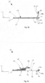
- Fig. 4a shows an embodiment of a schematically illustrated filter unit 27 of a laundry care appliance 1.
- the filter unit 27 comprises the filter housing 29.
- a filter membrane unit 39 is essentially arranged in the filter housing 29.
- the filter membrane unit 39 comprises a filter frame 41 and a filter membrane 43, wherein the filter membrane 43 is essentially arranged on the filter frame 41.
- the filter membrane 43 is often also referred to as a filter and/or lint filter or filter gauze.
- the filter membrane 43 comprises a filter membrane surface 47.
- the dirt particles, fluff, fibers and hair 45 are deposited on the filter membrane surface 47 in the flow direction (arrow A) of the fluid 15.
- the filtered fluid 15 flows in the flow direction (arrow B) to the filter outlet opening 33.
- a filter carpet 49 also referred to as a fluff carpet and/or dirt particle film and/or dirt particle carpet, forms on the filter membrane surface 47.
- the filter membrane 43 comprises at least a first region 51 and at least a second region 53.
- the at least one first region 51 of the filter membrane 43 of the at least one filter membrane unit 39 is designed differently than the at least one second region 53 of the filter membrane 43 of the at least one filter membrane unit 39.
- the at least one first region 51 of the filter membrane 43 is designed to be permeable to fluid 15 and the at least one second region 53 of the filter membrane 43 is designed to be impermeable to fluid 15.
- the at least one second region can also be referred to as at least one impermeable region or as an impermeable region.
- the at least one first region can also be referred to as at least one permeable region or as a permeable region.
- the at least one second region 53 of the filter membrane 43 is designed to be impermeable to fluid 15.
- At least one cover element 55 is provided for this purpose.
- the cover element 55 is arranged on or in the at least one second region 53 of the filter membrane 43 to cover the filter membrane 43.
- the at least one cover element 55 can be, for example, a film that is attached to or on the filter membrane surface 47.
- the at least one cover element 55 can be attached to a first filter membrane surface side 57 or to a second filter membrane surface side 59.
- the first filter membrane surface side 57 also referred to as the primary filter membrane surface, is, viewed in the flow direction of the fluid 15, the side that is initially acted upon by the fluid 15 as it flows through the filter unit 27.
- the second filter membrane surface side 59 also referred to as the secondary filter membrane surface, is opposite the first filter membrane surface side 57 and, viewed in the flow direction of the fluid 15, is formed on the side of the filter membrane on which the fluid 15 continues to flow after flowing through the filter membrane 43.
- the filter membrane 43 comprises a processed or compacted filter membrane surface 47a in the region of the at least one second region 53 of the filter membrane 43 such that no fluid 15 can flow through the at least one second region 53 of the filter membrane 43.
- a processed and/or compacted filter membrane surface 47a it is conceivable, for example, to weld the filter membrane surface 47a or to apply a material or substance that has been liquefied by heating, for example, such as plastic, resins or paints, which solidify again after cooling and thus form a covering element 55 or become an impermeable surface.
- the filter membrane 43 has a large number of membrane pores 56, which can be connected to one another, for example, by targeted heating of the filter membrane 43 or by another method mentioned, see, for example, above.
- the at least one second region 53 of the filter membrane 43 is provided with at least one cover element 55 and/or a processed or compacted filter membrane surface 47a is redesigned such that the at least one second region becomes impermeable.
- the at least one second region 53 of the filter membrane 43 is in Fig. 4a to Fig. 4d in an edge region 65a of the filter membrane 43.
- the at least one second region 53 of the filter membrane 43 is formed in a middle region of the filter membrane 65b. It is also conceivable that the filter membrane 43 comprises several second regions 53. More on this below.
- a start of a doctoring process of the schematically shown filter unit 27 is shown.
- a doctor unit 61 is shown.
- the doctor unit 61 essentially comprises at least one doctor element 63.
- the doctor unit 61 is essentially controlled by the control unit 23.
- the doctor unit 61 or the at least one doctor element 63 is shown in a starting position.
- the at least one doctor element 63 rests on or against the at least one impermeable region 53 of the filter membrane 43 (arrow B1).
- Fig. 4c an advanced doctoring process of the schematically illustrated filter unit 27 is shown.
- the doctoring unit 61 or the at least one doctoring element 63 is moved from the starting position, from the impermeable second region 53 of the filter membrane 43 in the direction (arrow B2) of the permeable first region 51.
- the at least one doctoring element 63 reaches under the filter carpet 49 formed on the permeable first region 51 and literally pulls the filter carpet 49 off or down from the filter membrane 43.
- Fig. 4d a plan view of the schematically illustrated filter unit 27 of a laundry care appliance 1 is shown. Clearly visible are the at least one first region 51 and the at least one second region 53 of the filter membrane 43 as well as the at least one squeegee element 63.
- the arrow B2 indicates the direction of movement of the at least one squeegee element 63.
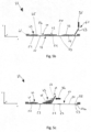
- FIG. 5a another embodiment of a schematically illustrated filter unit 27 of a laundry care appliance 1 is shown.
- Fig. 5a is a filter frame 41 and a Filter membrane 43 is shown.
- the filter membrane surface 47 of the filter membrane 43 comprises in the Fig. 5a to Fig. 5c at least two first regions 51 and at least two second regions 53.
- the filter membrane surface 47 comprises three first regions 51 and three second regions 53, which are regions impermeable to fluid 15.
- a plurality of second regions 53 are formed on the filter membrane 43.
- the plurality of second regions 53 can be arranged or arranged in any desired manner, preferably in a pattern, on the filter membrane 43 or on the filter membrane surface 47.
- the plurality of first regions 51 and the plurality of second regions 53 can extend in a checkerboard pattern over the filter membrane 43 or extend in a longitudinal or transverse direction of the filter membrane surface 47.
- the at least one doctor element 63 should rest against or on one of the impermeable regions of the plurality of second regions 53.
- a start of a squeegeeing process is shown using the further embodiment of the schematically shown filter unit 27 of a laundry care device 1.
- the at least one squeegee element 63 lies against or on one of the impermeable areas of the plurality of second areas 53 (arrow B1). Essentially no dirt particles, fibers, lint 45 and much more settle on or on the impermeable areas of the filter membrane 43, since the fluid 15 is in motion there and flows or is pumped to the permeable areas or a suction is created that sucks in the fluid 15 and the dirt particles 45 contained therein, so that the fluid 15 flows to the permeable areas.
- squeegee unit 61 with one squeegee element 63 is shown as an example.
- several squeegee units 61 are designed, each with one or more squeegee elements 63.
- the doctor element 63 starts from the starting position, an impermeable, second area 53, of the filter membrane 43 and is moved over a permeable area, a first area 51, of the filter membrane 43 (arrow B2 in Fig. 5c ). Following the permeable region, a first region 51, of the filter membrane 43, there follows another impermeable, second region 53 and so on.
- FIG. 5c an advanced squeegee process is shown using the further embodiment of the schematically shown filter unit 27 of a laundry care device 1.
- the at least one squeegee element 63 is moved from an impermeable area, second area 53, in the direction (arrow B2) of a permeable area, first area 51. In doing so, the at least one squeegee element 63 reaches under the filter carpet 49 that has accumulated there and literally pulls it away from the permeable area of the filter membrane 43.
- the multiple second areas 53 ensure that the at least one squeegee element 63, when it is placed on a further first area 51, again reaches under the filter carpet 49 that has accumulated there and pulls it away from the permeable area of the filter membrane 43.
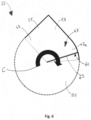
- FIG. 6 A further embodiment of a schematically illustrated filter unit 27 of a laundry care appliance 1 is shown in Fig. 6 shown.
- the filter unit 27 essentially comprises a filter membrane 43, at least one doctor element 63.
- the filter membrane 43 comprises a first region 51, which is permeable to fluid 15, and a second region 53, which is impermeable to fluid 15.
- a plurality of first regions 51 and a plurality of second regions 53 can also be provided.
- the filter membrane 43 or the filter membrane surface 47 is in Fig. 6 for example, drop-shaped.
- the impermeable area 53 is in Fig. 6 in a tapered end of the drop-shaped filter membrane 43.
- Arrow C represents a direction of rotation of the doctor element 63.
- the doctor element 63 is moved from the impermeable area of the filter membrane 43 in a circular motion over the filter membrane surface 47 and detaches the filter carpet 49 (not shown here) from the filter membrane surface 47 and doctor the detached filter carpet 49 in the direction of the tapered end of the drop-shaped filter membrane 43.
- the doctor element 63 is always moved from the impermeable area over the permeable area and back to the impermeable area.
- the second area 53 of the filter membrane 43 can have a cover element 55 and/or a machined filter membrane surface 47a.
Landscapes
- Engineering & Computer Science (AREA)
- Textile Engineering (AREA)
- Accessory Of Washing/Drying Machine, Commercial Washing/Drying Machine, Other Washing/Drying Machine (AREA)
- Detail Structures Of Washing Machines And Dryers (AREA)
Claims (14)
- Appareil d'entretien du linge (1) pour le traitement d'objets avec au moins une unité de filtre (27) pour filtrer du fluide (15), qui s'écoule dans l'appareil d'entretien du linge (1), dans lequel la au moins une unité de filtre (27) comprend un boîtier de filtre (29), dans lequel sont disposés dans le boîtier de filtre (29) de la au moins une unité de filtre (27) au moins une unité de membrane de filtre (39) et au moins une unité de raclage (61), dans lequel la au moins une unité de membrane de filtre (39) comprend un cadre de filtre (41) et une membrane de filtre (43), dans lequel la membrane de filtre (43) est disposée essentiellement sur le cadre de filtre (41) et dans lequel du fluide (15) s'écoule par la membrane de filtre (43), caractérisé en ce que la membrane de filtre (43) comprend au moins une première zone (51) et au moins une deuxième zone (53), dans lequel la au moins une première zone (51) de la membrane de filtre (43) de la au moins une unité de membrane de filtre (39) est conçue d'une manière différente à la au moins une deuxième zone (53) de la membrane de filtre (43) de la au moins une unité de membrane de filtre (39),
dans lequel la au moins une première zone (51) de la membrane de filtre (43) est conçue perméable pour du fluide (15) et la au moins une deuxième zone (53) de la membrane de filtre (43) est conçue imperméable pour du fluide (15). - Appareil d'entretien du linge (1) selon la revendication 1, caractérisé en ce que la au moins une unité de filtre (27) est disposée dans un système de transvasement par pompe (30a) de l'appareil d'entretien du linge (1) et/ou dans un système de pompage (30b) de l'appareil d'entretien du linge (1).
- Appareil d'entretien du linge (1) selon la revendication 1 ou la revendication 2, caractérisé en ce qu'au moins une unité de commande (23) est conçue pour contrôler la au moins une unité de raclage (61) et la au moins une unité de raclage (61) comprend au moins un élément de raclage (63), dans lequel l'unité de commande (23) est conçue de manière à contrôler la au moins une unité de raclage (61) de sorte que le au moins un élément de raclage (63) racle la membrane de filtre (43).
- Appareil d'entretien du linge (1) selon la revendication 3, caractérisé en ce que le au moins un élément de raclage (63) de la au moins une unité de raclage (61) avant le début d'un processus de raclage est adjacent à la au moins une deuxième zone (53) de la membrane de filtre (43).
- Appareil d'entretien du linge (1) selon la revendication 3 ou la revendication 4, caractérisé en ce que le au moins un élément de raclage (63) est adjacent à une surface de membrane de filtre (47) de la membrane de filtre (43) qui sollicite le fluide (15) dans le sens d'écoulement (A).
- Appareil d'entretien du linge (1) selon l'une des revendications 3 à 5, caractérisé en ce que le au moins un élément de raclage (63) de la au moins une unité de raclage (61) après achèvement d'un processus de raclage est adjacent à la au moins une deuxième zone (53) de la membrane de filtre (43).
- Appareil d'entretien du linge (1) selon l'une des revendications précédentes, caractérisé en ce que la au moins une deuxième zone (53) de la membrane de filtre (43) est conçue dans une zone marginale (65a) de la membrane de filtre (43).
- Appareil d'entretien du linge (1) selon l'une des revendications précédentes, en combinaison avec la revendication 3, caractérisé en ce que la au moins une première zone (51) de la membrane de filtre (43) comprend au moins deux premières zones (51) et la au moins une deuxième zone (53) de la membrane de filtre (43) comprend au moins deux deuxièmes zones (53), dans lequel l'unité de raclage (61) avant le début du processus de raclage est adjacente à au moins une deuxième zone (53) de la membrane de filtre (43).
- Appareil d'entretien du linge (1) selon la revendication 8, caractérisé en ce que les au moins deux premières zones (51) de la membrane de filtre (43) et les au moins deux deuxièmes zones (53) de la membrane de filtre (43) sont conçues sous forme de motifs sur la membrane de filtre (43).
- Appareil d'entretien du linge (1) selon l'une des revendications précédentes, caractérisé en ce qu'au moins un élément de recouvrement (55) pour recouvrir la membrane de filtre (43) est disposé sur la au moins une deuxième zone (53) de la membrane de filtre (43).
- Appareil d'entretien du linge (1) selon l'une des revendications 1 à 9, caractérisé en ce que la membrane de filtre (43) comprend une surface de membrane de filtre (47), dans lequel la surface de membrane de filtre (47) présente dans la zone de la au moins une deuxième zone (53) de la membrane de filtre (43) une surface de membrane de filtre usinée (47a).
- Appareil d'entretien du linge (1) selon l'une des revendications 1 à 9, caractérisé en ce que la membrane de filtre (43) comprend une surface de membrane de filtre (47), dans lequel au moins un élément de recouvrement (55) est disposé à la au moins une deuxième zone (53) de la membrane de filtre (43) et/ou la surface de la membrane de filtre (47) présente dans la zone de la au moins une deuxième zone (53) de la membrane de filtre (47) une surface de membrane de filtre usinée (47a).
- Procédé de nettoyage d'une membrane de filtre (43) d'une unité de filtre (27) d'un appareil d'entretien du linge (1) avec une unité de raclage (61), dans lequel l'unité de raclage (61) comprend au moins un élément de raclage (63) et dans lequel la membrane de filtre (43) présente au moins une première zone (51) et au moins une deuxième zone (53), dans lequel la au moins une première zone (51) et la au moins une deuxième zone (53) sont conçues différemment, et la au moins une première zone (51) de la membrane de filtre (43) est conçue perméable pour du fluide (15) et la au moins une deuxième zone (53) de la membrane de filtre (43) est conçue imperméable pour du fluide (15), dans lequel le au moins un élément de raclage (63) de l'unité de raclage (61) avant le début d'un processus de raclage est dans une position de départ de sorte que le au moins un élément de raclage (63) sur la au moins une deuxième zone (53) de la membrane de filtre (43), qui est imperméable pour du fluide (15), est adjacent, et le au moins un élément de raclage (63) lors du début du processus de raclage est déplacé de la au moins une deuxième zone (53) de la membrane de filtre (43) dans le sens de la au moins une première zone (51) de la membrane de filtre (43).
- Procédé selon la revendication 13, caractérisé en ce que lors du fonctionnement de l'appareil d'entretien du linge (1), un tapis filtrant (49) est formé dans le sens d'écoulement (A) du fluide (15) sur la membrane de filtre (43) de l'unité de filtre (27) et le au moins un élément de raclage (63) de l'unité de raclage (61) lors du déplacement du au moins un élément de raclage (63), de la au moins une deuxième zone (53) de la membrane de filtre (43) dans le sens (B2) de la au moins une première zone (51) de la membrane de filtre (43), soulève essentiellement le tapis filtrant (49) et le au moins un élément de raclage (63) est déplacé essentiellement entre le tapis filtrant (49) et la membrane de filtre (43).
Applications Claiming Priority (1)
| Application Number | Priority Date | Filing Date | Title |
|---|---|---|---|
| DE102021205973.2A DE102021205973A1 (de) | 2021-06-11 | 2021-06-11 | Wäschepflegegerät zur Behandlung von Gegenständen |
Publications (2)
| Publication Number | Publication Date |
|---|---|
| EP4101970A1 EP4101970A1 (fr) | 2022-12-14 |
| EP4101970B1 true EP4101970B1 (fr) | 2024-11-06 |
Family
ID=81846521
Family Applications (1)
| Application Number | Title | Priority Date | Filing Date |
|---|---|---|---|
| EP22174058.2A Active EP4101970B1 (fr) | 2021-06-11 | 2022-05-18 | Appareil d'entretien du linge et procédé destiné au traitement des objets |
Country Status (2)
| Country | Link |
|---|---|
| EP (1) | EP4101970B1 (fr) |
| DE (1) | DE102021205973A1 (fr) |
Families Citing this family (1)
| Publication number | Priority date | Publication date | Assignee | Title |
|---|---|---|---|---|
| DE102023112522A1 (de) * | 2023-05-11 | 2024-11-14 | Hengst Se | Wechselbehälter für Haushaltswaschmaschinen |
Family Cites Families (10)
| Publication number | Priority date | Publication date | Assignee | Title |
|---|---|---|---|---|
| IT1192076B (it) | 1986-04-09 | 1988-03-31 | Zanussi Elettrodomestici | Filtro per macchine lavabiancheria |
| US5463820A (en) * | 1992-09-14 | 1995-11-07 | La Rue; Len | Lint filter |
| DE102005054684A1 (de) | 2005-11-16 | 2007-05-24 | BSH Bosch und Siemens Hausgeräte GmbH | Vorrichtung zum Trocknen von Wäsche mittels eines Luftstroms |
| FR2931487B1 (fr) * | 2008-05-20 | 2010-12-17 | Fagorbrandt Sas | Machine a secher le linge comprenant un filtre a peluches |
| KR100989734B1 (ko) * | 2008-06-03 | 2010-10-26 | 엘지전자 주식회사 | 의류건조기 |
| AU2011249155B2 (en) * | 2010-05-04 | 2014-09-25 | Lg Electronics Inc. | Clothes treating apparatus with substance removal, collection and compression units for the filter unit |
| KR101716821B1 (ko) * | 2010-10-12 | 2017-03-15 | 삼성전자주식회사 | 의류건조기 및 이에 구비되는 린트 청소장치 |
| EP2455533B1 (fr) | 2010-11-22 | 2014-06-18 | Electrolux Home Products Corporation N.V. | Procédé de fonctionnement d'une machine à laver et machine à laver |
| KR102029241B1 (ko) | 2012-12-07 | 2019-10-07 | 엘지전자 주식회사 | 의류처리장치의 제어방법 |
| DE102019204990A1 (de) | 2019-04-08 | 2020-10-08 | BSH Hausgeräte GmbH | System zum Reinigen eines Membranelements, insbesondere eines Membranelements eines wasserführenden Haushaltsgeräts, Rakelelement und Verfahren zum Reinigen eines Membranelements |
-
2021
- 2021-06-11 DE DE102021205973.2A patent/DE102021205973A1/de active Pending
-
2022
- 2022-05-18 EP EP22174058.2A patent/EP4101970B1/fr active Active
Also Published As
| Publication number | Publication date |
|---|---|
| EP4101970A1 (fr) | 2022-12-14 |
| DE102021205973A1 (de) | 2022-12-15 |
Similar Documents
| Publication | Publication Date | Title |
|---|---|---|
| EP2334864B1 (fr) | Séchoir équipé d'un filtre à peluches et d'un dispositif de nettoyage | |
| DE69618861T2 (de) | Geschirrspülmaschine mit Filtereinrichtung und -verfahren | |
| DE69712267T2 (de) | Haushalts-Wasch- und Trockenmaschine mit geschlossenem Trocknungskreislauf, Luftkondensation und selbstreinigendem Filter | |
| EP2422010B1 (fr) | Sèche-linge domestique et procédé de filtrage | |
| DE69205632T2 (de) | Verfahren und Vorrichtung zur Beseitigung von Flusen in Wasch-und-Trocknermaschinen. | |
| EP2202349A2 (fr) | Appareil de séchage de linge et procédé de nettoyage d'un crible | |
| WO2011061068A1 (fr) | Dispositif de séchage comprenant un filtre à peluches et un dispositif de nettoyage | |
| EP3854930B1 (fr) | Appareil électroménager à circulation d'eau comprenant une unité de filtration | |
| DE102022207949A1 (de) | Fluidführendes Haushaltsgerät | |
| EP3954820A1 (fr) | Appareil électroménager à circulation de fluide | |
| DE102015223192A1 (de) | Betreiben eines Wäschetrocknungsgeräts mit einem Flusensieb und einer Flusenfalle | |
| EP4101970B1 (fr) | Appareil d'entretien du linge et procédé destiné au traitement des objets | |
| EP3696311A1 (fr) | Appareil électroménager destiné au traitement du linge | |
| EP3663457B1 (fr) | Appareil électroménager conducteur d'eau et procédé de filtrage des fluides dans un appareil électroménager conducteur d'eau | |
| EP3608465B1 (fr) | Appareil électroménager destiné au traitement du linge | |
| EP3172372B1 (fr) | Appareil ménager doté d'une conduite pour liquide | |
| DE29608272U1 (de) | Kombinierte Maschine zum Waschen und Trocknen von Wäsche | |
| DE102009046920A1 (de) | Verfahren zum Reinigen einer Prozessluft eines Wäschetrocknungsgeräts und Wäschetrocknungsgerät | |
| EP3866663B1 (fr) | Lave-vaisselle ménager pourvu d'un système de filtre autonettoyant | |
| DE4132431A1 (de) | Waeschebehandlungsmaschine wie waeschetrockner oder waschtrockner | |
| EP4065755B1 (fr) | Lavage à contre-courant | |
| DE69610796T2 (de) | Wäschewaschmaschine mit Vorrichtung zum Filtern der Waschlauge | |
| EP4328373A1 (fr) | Tuyau d'introduction pour un appareil ménager à circulation d'eau | |
| DE102017116611A1 (de) | Flusenabscheidevorrichtung für einen Trockner und Verfahren zum Betreiben einer Flusenabscheidevorrichtung | |
| EP3786343A1 (fr) | Appareil de traitement du linge |
Legal Events
| Date | Code | Title | Description |
|---|---|---|---|
| PUAI | Public reference made under article 153(3) epc to a published international application that has entered the european phase |
Free format text: ORIGINAL CODE: 0009012 |
|
| STAA | Information on the status of an ep patent application or granted ep patent |
Free format text: STATUS: THE APPLICATION HAS BEEN PUBLISHED |
|
| AK | Designated contracting states |
Kind code of ref document: A1 Designated state(s): AL AT BE BG CH CY CZ DE DK EE ES FI FR GB GR HR HU IE IS IT LI LT LU LV MC MK MT NL NO PL PT RO RS SE SI SK SM TR |
|
| STAA | Information on the status of an ep patent application or granted ep patent |
Free format text: STATUS: REQUEST FOR EXAMINATION WAS MADE |
|
| 17P | Request for examination filed |
Effective date: 20230614 |
|
| RBV | Designated contracting states (corrected) |
Designated state(s): AL AT BE BG CH CY CZ DE DK EE ES FI FR GB GR HR HU IE IS IT LI LT LU LV MC MK MT NL NO PL PT RO RS SE SI SK SM TR |
|
| GRAP | Despatch of communication of intention to grant a patent |
Free format text: ORIGINAL CODE: EPIDOSNIGR1 |
|
| STAA | Information on the status of an ep patent application or granted ep patent |
Free format text: STATUS: GRANT OF PATENT IS INTENDED |
|
| INTG | Intention to grant announced |
Effective date: 20240321 |
|
| GRAJ | Information related to disapproval of communication of intention to grant by the applicant or resumption of examination proceedings by the epo deleted |
Free format text: ORIGINAL CODE: EPIDOSDIGR1 |
|
| STAA | Information on the status of an ep patent application or granted ep patent |
Free format text: STATUS: REQUEST FOR EXAMINATION WAS MADE |
|
| GRAP | Despatch of communication of intention to grant a patent |
Free format text: ORIGINAL CODE: EPIDOSNIGR1 |
|
| STAA | Information on the status of an ep patent application or granted ep patent |
Free format text: STATUS: GRANT OF PATENT IS INTENDED |
|
| INTC | Intention to grant announced (deleted) | ||
| INTG | Intention to grant announced |
Effective date: 20240718 |
|
| GRAS | Grant fee paid |
Free format text: ORIGINAL CODE: EPIDOSNIGR3 |
|
| GRAA | (expected) grant |
Free format text: ORIGINAL CODE: 0009210 |
|
| STAA | Information on the status of an ep patent application or granted ep patent |
Free format text: STATUS: THE PATENT HAS BEEN GRANTED |
|
| AK | Designated contracting states |
Kind code of ref document: B1 Designated state(s): AL AT BE BG CH CY CZ DE DK EE ES FI FR GB GR HR HU IE IS IT LI LT LU LV MC MK MT NL NO PL PT RO RS SE SI SK SM TR |
|
| REG | Reference to a national code |
Ref country code: GB Ref legal event code: FG4D Free format text: NOT ENGLISH |
|
| REG | Reference to a national code |
Ref country code: CH Ref legal event code: EP |
|
| REG | Reference to a national code |
Ref country code: DE Ref legal event code: R096 Ref document number: 502022002053 Country of ref document: DE |
|
| REG | Reference to a national code |
Ref country code: IE Ref legal event code: FG4D Free format text: LANGUAGE OF EP DOCUMENT: GERMAN |
|
| REG | Reference to a national code |
Ref country code: LT Ref legal event code: MG9D |
|
| REG | Reference to a national code |
Ref country code: NL Ref legal event code: MP Effective date: 20241106 |
|
| PG25 | Lapsed in a contracting state [announced via postgrant information from national office to epo] |
Ref country code: IS Free format text: LAPSE BECAUSE OF FAILURE TO SUBMIT A TRANSLATION OF THE DESCRIPTION OR TO PAY THE FEE WITHIN THE PRESCRIBED TIME-LIMIT Effective date: 20250306 Ref country code: HR Free format text: LAPSE BECAUSE OF FAILURE TO SUBMIT A TRANSLATION OF THE DESCRIPTION OR TO PAY THE FEE WITHIN THE PRESCRIBED TIME-LIMIT Effective date: 20241106 Ref country code: PT Free format text: LAPSE BECAUSE OF FAILURE TO SUBMIT A TRANSLATION OF THE DESCRIPTION OR TO PAY THE FEE WITHIN THE PRESCRIBED TIME-LIMIT Effective date: 20250306 |
|
| PG25 | Lapsed in a contracting state [announced via postgrant information from national office to epo] |
Ref country code: FI Free format text: LAPSE BECAUSE OF FAILURE TO SUBMIT A TRANSLATION OF THE DESCRIPTION OR TO PAY THE FEE WITHIN THE PRESCRIBED TIME-LIMIT Effective date: 20241106 Ref country code: NL Free format text: LAPSE BECAUSE OF FAILURE TO SUBMIT A TRANSLATION OF THE DESCRIPTION OR TO PAY THE FEE WITHIN THE PRESCRIBED TIME-LIMIT Effective date: 20241106 |
|
| PG25 | Lapsed in a contracting state [announced via postgrant information from national office to epo] |
Ref country code: BG Free format text: LAPSE BECAUSE OF FAILURE TO SUBMIT A TRANSLATION OF THE DESCRIPTION OR TO PAY THE FEE WITHIN THE PRESCRIBED TIME-LIMIT Effective date: 20241106 |
|
| PG25 | Lapsed in a contracting state [announced via postgrant information from national office to epo] |
Ref country code: ES Free format text: LAPSE BECAUSE OF FAILURE TO SUBMIT A TRANSLATION OF THE DESCRIPTION OR TO PAY THE FEE WITHIN THE PRESCRIBED TIME-LIMIT Effective date: 20241106 |
|
| PG25 | Lapsed in a contracting state [announced via postgrant information from national office to epo] |
Ref country code: NO Free format text: LAPSE BECAUSE OF FAILURE TO SUBMIT A TRANSLATION OF THE DESCRIPTION OR TO PAY THE FEE WITHIN THE PRESCRIBED TIME-LIMIT Effective date: 20250206 |
|
| PG25 | Lapsed in a contracting state [announced via postgrant information from national office to epo] |
Ref country code: LV Free format text: LAPSE BECAUSE OF FAILURE TO SUBMIT A TRANSLATION OF THE DESCRIPTION OR TO PAY THE FEE WITHIN THE PRESCRIBED TIME-LIMIT Effective date: 20241106 Ref country code: GR Free format text: LAPSE BECAUSE OF FAILURE TO SUBMIT A TRANSLATION OF THE DESCRIPTION OR TO PAY THE FEE WITHIN THE PRESCRIBED TIME-LIMIT Effective date: 20250207 |
|
| PG25 | Lapsed in a contracting state [announced via postgrant information from national office to epo] |
Ref country code: PL Free format text: LAPSE BECAUSE OF FAILURE TO SUBMIT A TRANSLATION OF THE DESCRIPTION OR TO PAY THE FEE WITHIN THE PRESCRIBED TIME-LIMIT Effective date: 20241106 |
|
| PG25 | Lapsed in a contracting state [announced via postgrant information from national office to epo] |
Ref country code: RS Free format text: LAPSE BECAUSE OF FAILURE TO SUBMIT A TRANSLATION OF THE DESCRIPTION OR TO PAY THE FEE WITHIN THE PRESCRIBED TIME-LIMIT Effective date: 20250206 |
|
| PG25 | Lapsed in a contracting state [announced via postgrant information from national office to epo] |
Ref country code: SM Free format text: LAPSE BECAUSE OF FAILURE TO SUBMIT A TRANSLATION OF THE DESCRIPTION OR TO PAY THE FEE WITHIN THE PRESCRIBED TIME-LIMIT Effective date: 20241106 |
|
| PGFP | Annual fee paid to national office [announced via postgrant information from national office to epo] |
Ref country code: DE Payment date: 20250531 Year of fee payment: 4 |
|
| PG25 | Lapsed in a contracting state [announced via postgrant information from national office to epo] |
Ref country code: DK Free format text: LAPSE BECAUSE OF FAILURE TO SUBMIT A TRANSLATION OF THE DESCRIPTION OR TO PAY THE FEE WITHIN THE PRESCRIBED TIME-LIMIT Effective date: 20241106 |
|
| PG25 | Lapsed in a contracting state [announced via postgrant information from national office to epo] |
Ref country code: EE Free format text: LAPSE BECAUSE OF FAILURE TO SUBMIT A TRANSLATION OF THE DESCRIPTION OR TO PAY THE FEE WITHIN THE PRESCRIBED TIME-LIMIT Effective date: 20241106 |
|
| PGFP | Annual fee paid to national office [announced via postgrant information from national office to epo] |
Ref country code: FR Payment date: 20250523 Year of fee payment: 4 |
|
| PG25 | Lapsed in a contracting state [announced via postgrant information from national office to epo] |
Ref country code: RO Free format text: LAPSE BECAUSE OF FAILURE TO SUBMIT A TRANSLATION OF THE DESCRIPTION OR TO PAY THE FEE WITHIN THE PRESCRIBED TIME-LIMIT Effective date: 20241106 |
|
| PGFP | Annual fee paid to national office [announced via postgrant information from national office to epo] |
Ref country code: AT Payment date: 20250721 Year of fee payment: 4 |
|
| PG25 | Lapsed in a contracting state [announced via postgrant information from national office to epo] |
Ref country code: SK Free format text: LAPSE BECAUSE OF FAILURE TO SUBMIT A TRANSLATION OF THE DESCRIPTION OR TO PAY THE FEE WITHIN THE PRESCRIBED TIME-LIMIT Effective date: 20241106 |
|
| PGFP | Annual fee paid to national office [announced via postgrant information from national office to epo] |
Ref country code: TR Payment date: 20250508 Year of fee payment: 4 |
|
| PG25 | Lapsed in a contracting state [announced via postgrant information from national office to epo] |
Ref country code: CZ Free format text: LAPSE BECAUSE OF FAILURE TO SUBMIT A TRANSLATION OF THE DESCRIPTION OR TO PAY THE FEE WITHIN THE PRESCRIBED TIME-LIMIT Effective date: 20241106 |
|
| PG25 | Lapsed in a contracting state [announced via postgrant information from national office to epo] |
Ref country code: IT Free format text: LAPSE BECAUSE OF FAILURE TO SUBMIT A TRANSLATION OF THE DESCRIPTION OR TO PAY THE FEE WITHIN THE PRESCRIBED TIME-LIMIT Effective date: 20241106 |
|
| REG | Reference to a national code |
Ref country code: DE Ref legal event code: R097 Ref document number: 502022002053 Country of ref document: DE |
|
| PG25 | Lapsed in a contracting state [announced via postgrant information from national office to epo] |
Ref country code: SE Free format text: LAPSE BECAUSE OF FAILURE TO SUBMIT A TRANSLATION OF THE DESCRIPTION OR TO PAY THE FEE WITHIN THE PRESCRIBED TIME-LIMIT Effective date: 20241106 |
|
| PLBE | No opposition filed within time limit |
Free format text: ORIGINAL CODE: 0009261 |
|
| STAA | Information on the status of an ep patent application or granted ep patent |
Free format text: STATUS: NO OPPOSITION FILED WITHIN TIME LIMIT |
|
| 26N | No opposition filed |
Effective date: 20250807 |
|
| REG | Reference to a national code |
Ref country code: CH Ref legal event code: H13 Free format text: ST27 STATUS EVENT CODE: U-0-0-H10-H13 (AS PROVIDED BY THE NATIONAL OFFICE) Effective date: 20251223 |
|
| PG25 | Lapsed in a contracting state [announced via postgrant information from national office to epo] |
Ref country code: LU Free format text: LAPSE BECAUSE OF NON-PAYMENT OF DUE FEES Effective date: 20250518 |
|
| PG25 | Lapsed in a contracting state [announced via postgrant information from national office to epo] |
Ref country code: CH Free format text: LAPSE BECAUSE OF NON-PAYMENT OF DUE FEES Effective date: 20250531 |
|
| REG | Reference to a national code |
Ref country code: BE Ref legal event code: MM Effective date: 20250531 |
|
| PG25 | Lapsed in a contracting state [announced via postgrant information from national office to epo] |
Ref country code: MC Free format text: LAPSE BECAUSE OF FAILURE TO SUBMIT A TRANSLATION OF THE DESCRIPTION OR TO PAY THE FEE WITHIN THE PRESCRIBED TIME-LIMIT Effective date: 20241106 |
|
| PG25 | Lapsed in a contracting state [announced via postgrant information from national office to epo] |
Ref country code: IE Free format text: LAPSE BECAUSE OF NON-PAYMENT OF DUE FEES Effective date: 20250518 |
|
| PG25 | Lapsed in a contracting state [announced via postgrant information from national office to epo] |
Ref country code: BE Free format text: LAPSE BECAUSE OF NON-PAYMENT OF DUE FEES Effective date: 20250531 |