EP4101983B1 - Elektrischer antrieb für eine bodenoberflächenmodifizierungsmaschine auf rädern - Google Patents
Elektrischer antrieb für eine bodenoberflächenmodifizierungsmaschine auf rädern Download PDFInfo
- Publication number
- EP4101983B1 EP4101983B1 EP22180206.9A EP22180206A EP4101983B1 EP 4101983 B1 EP4101983 B1 EP 4101983B1 EP 22180206 A EP22180206 A EP 22180206A EP 4101983 B1 EP4101983 B1 EP 4101983B1
- Authority
- EP
- European Patent Office
- Prior art keywords
- speed
- pedal
- driver
- range
- tilt
- Prior art date
- Legal status (The legal status is an assumption and is not a legal conclusion. Google has not performed a legal analysis and makes no representation as to the accuracy of the status listed.)
- Active
Links
Images





Classifications
-
- B—PERFORMING OPERATIONS; TRANSPORTING
- B60—VEHICLES IN GENERAL
- B60L—PROPULSION OF ELECTRICALLY-PROPELLED VEHICLES; SUPPLYING ELECTRIC POWER FOR AUXILIARY EQUIPMENT OF ELECTRICALLY-PROPELLED VEHICLES; ELECTRODYNAMIC BRAKE SYSTEMS FOR VEHICLES IN GENERAL; MAGNETIC SUSPENSION OR LEVITATION FOR VEHICLES; MONITORING OPERATING VARIABLES OF ELECTRICALLY-PROPELLED VEHICLES; ELECTRIC SAFETY DEVICES FOR ELECTRICALLY-PROPELLED VEHICLES
- B60L15/00—Methods, circuits, or devices for controlling the traction-motor speed of electrically-propelled vehicles
- B60L15/20—Methods, circuits, or devices for controlling the traction-motor speed of electrically-propelled vehicles for control of the vehicle or its driving motor to achieve a desired performance, e.g. speed, torque, programmed variation of speed
-
- B—PERFORMING OPERATIONS; TRANSPORTING
- B62—LAND VEHICLES FOR TRAVELLING OTHERWISE THAN ON RAILS
- B62D—MOTOR VEHICLES; TRAILERS
- B62D53/00—Tractor-trailer combinations; Road trains
- B62D53/02—Tractor-trailer combinations; Road trains comprising a uniaxle tractor unit and a uniaxle trailer unit
-
- B—PERFORMING OPERATIONS; TRANSPORTING
- B60—VEHICLES IN GENERAL
- B60D—VEHICLE CONNECTIONS
- B60D1/00—Traction couplings; Hitches; Draw-gear; Towing devices
- B60D1/48—Traction couplings; Hitches; Draw-gear; Towing devices characterised by the mounting
- B60D1/488—Traction couplings; Hitches; Draw-gear; Towing devices characterised by the mounting mounted directly to the chassis of the towing vehicle
-
- B—PERFORMING OPERATIONS; TRANSPORTING
- B60—VEHICLES IN GENERAL
- B60K—ARRANGEMENT OR MOUNTING OF PROPULSION UNITS OR OF TRANSMISSIONS IN VEHICLES; ARRANGEMENT OR MOUNTING OF PLURAL DIVERSE PRIME-MOVERS IN VEHICLES; AUXILIARY DRIVES FOR VEHICLES; INSTRUMENTATION OR DASHBOARDS FOR VEHICLES; ARRANGEMENTS IN CONNECTION WITH COOLING, AIR INTAKE, GAS EXHAUST OR FUEL SUPPLY OF PROPULSION UNITS IN VEHICLES
- B60K1/00—Arrangement or mounting of electrical propulsion units
-
- B—PERFORMING OPERATIONS; TRANSPORTING
- B60—VEHICLES IN GENERAL
- B60K—ARRANGEMENT OR MOUNTING OF PROPULSION UNITS OR OF TRANSMISSIONS IN VEHICLES; ARRANGEMENT OR MOUNTING OF PLURAL DIVERSE PRIME-MOVERS IN VEHICLES; AUXILIARY DRIVES FOR VEHICLES; INSTRUMENTATION OR DASHBOARDS FOR VEHICLES; ARRANGEMENTS IN CONNECTION WITH COOLING, AIR INTAKE, GAS EXHAUST OR FUEL SUPPLY OF PROPULSION UNITS IN VEHICLES
- B60K1/00—Arrangement or mounting of electrical propulsion units
- B60K1/04—Arrangement or mounting of electrical propulsion units of the electric storage means for propulsion
-
- B—PERFORMING OPERATIONS; TRANSPORTING
- B60—VEHICLES IN GENERAL
- B60K—ARRANGEMENT OR MOUNTING OF PROPULSION UNITS OR OF TRANSMISSIONS IN VEHICLES; ARRANGEMENT OR MOUNTING OF PLURAL DIVERSE PRIME-MOVERS IN VEHICLES; AUXILIARY DRIVES FOR VEHICLES; INSTRUMENTATION OR DASHBOARDS FOR VEHICLES; ARRANGEMENTS IN CONNECTION WITH COOLING, AIR INTAKE, GAS EXHAUST OR FUEL SUPPLY OF PROPULSION UNITS IN VEHICLES
- B60K26/00—Arrangement or mounting of propulsion-unit control devices in vehicles
- B60K26/02—Arrangement or mounting of propulsion-unit control devices in vehicles of initiating means or elements
-
- B—PERFORMING OPERATIONS; TRANSPORTING
- B60—VEHICLES IN GENERAL
- B60L—PROPULSION OF ELECTRICALLY-PROPELLED VEHICLES; SUPPLYING ELECTRIC POWER FOR AUXILIARY EQUIPMENT OF ELECTRICALLY-PROPELLED VEHICLES; ELECTRODYNAMIC BRAKE SYSTEMS FOR VEHICLES IN GENERAL; MAGNETIC SUSPENSION OR LEVITATION FOR VEHICLES; MONITORING OPERATING VARIABLES OF ELECTRICALLY-PROPELLED VEHICLES; ELECTRIC SAFETY DEVICES FOR ELECTRICALLY-PROPELLED VEHICLES
- B60L50/00—Electric propulsion with power supplied within the vehicle
- B60L50/50—Electric propulsion with power supplied within the vehicle using propulsion power supplied by batteries or fuel cells
- B60L50/60—Electric propulsion with power supplied within the vehicle using propulsion power supplied by batteries or fuel cells using power supplied by batteries
- B60L50/66—Arrangements of batteries
-
- B—PERFORMING OPERATIONS; TRANSPORTING
- B60—VEHICLES IN GENERAL
- B60R—VEHICLES, VEHICLE FITTINGS, OR VEHICLE PARTS, NOT OTHERWISE PROVIDED FOR
- B60R16/00—Electric or fluid circuits specially adapted for vehicles and not otherwise provided for; Arrangement of elements of electric or fluid circuits specially adapted for vehicles and not otherwise provided for
- B60R16/02—Electric or fluid circuits specially adapted for vehicles and not otherwise provided for; Arrangement of elements of electric or fluid circuits specially adapted for vehicles and not otherwise provided for electric constitutive elements
-
- E—FIXED CONSTRUCTIONS
- E01—CONSTRUCTION OF ROADS, RAILWAYS, OR BRIDGES
- E01C—CONSTRUCTION OF, OR SURFACES FOR, ROADS, SPORTS GROUNDS, OR THE LIKE; MACHINES OR AUXILIARY TOOLS FOR CONSTRUCTION OR REPAIR
- E01C23/00—Auxiliary devices or arrangements for constructing, repairing, reconditioning, or taking-up road or like surfaces
- E01C23/16—Devices for marking-out, applying, or forming traffic or like markings on finished paving; Protecting fresh markings
-
- B—PERFORMING OPERATIONS; TRANSPORTING
- B60—VEHICLES IN GENERAL
- B60K—ARRANGEMENT OR MOUNTING OF PROPULSION UNITS OR OF TRANSMISSIONS IN VEHICLES; ARRANGEMENT OR MOUNTING OF PLURAL DIVERSE PRIME-MOVERS IN VEHICLES; AUXILIARY DRIVES FOR VEHICLES; INSTRUMENTATION OR DASHBOARDS FOR VEHICLES; ARRANGEMENTS IN CONNECTION WITH COOLING, AIR INTAKE, GAS EXHAUST OR FUEL SUPPLY OF PROPULSION UNITS IN VEHICLES
- B60K1/00—Arrangement or mounting of electrical propulsion units
- B60K2001/001—Arrangement or mounting of electrical propulsion units one motor mounted on a propulsion axle for rotating right and left wheels of this axle
-
- B—PERFORMING OPERATIONS; TRANSPORTING
- B60—VEHICLES IN GENERAL
- B60K—ARRANGEMENT OR MOUNTING OF PROPULSION UNITS OR OF TRANSMISSIONS IN VEHICLES; ARRANGEMENT OR MOUNTING OF PLURAL DIVERSE PRIME-MOVERS IN VEHICLES; AUXILIARY DRIVES FOR VEHICLES; INSTRUMENTATION OR DASHBOARDS FOR VEHICLES; ARRANGEMENTS IN CONNECTION WITH COOLING, AIR INTAKE, GAS EXHAUST OR FUEL SUPPLY OF PROPULSION UNITS IN VEHICLES
- B60K1/00—Arrangement or mounting of electrical propulsion units
- B60K1/04—Arrangement or mounting of electrical propulsion units of the electric storage means for propulsion
- B60K2001/0405—Arrangement or mounting of electrical propulsion units of the electric storage means for propulsion characterised by their position
- B60K2001/0444—Arrangement on a trailer
-
- B—PERFORMING OPERATIONS; TRANSPORTING
- B60—VEHICLES IN GENERAL
- B60K—ARRANGEMENT OR MOUNTING OF PROPULSION UNITS OR OF TRANSMISSIONS IN VEHICLES; ARRANGEMENT OR MOUNTING OF PLURAL DIVERSE PRIME-MOVERS IN VEHICLES; AUXILIARY DRIVES FOR VEHICLES; INSTRUMENTATION OR DASHBOARDS FOR VEHICLES; ARRANGEMENTS IN CONNECTION WITH COOLING, AIR INTAKE, GAS EXHAUST OR FUEL SUPPLY OF PROPULSION UNITS IN VEHICLES
- B60K26/00—Arrangement or mounting of propulsion-unit control devices in vehicles
- B60K26/02—Arrangement or mounting of propulsion-unit control devices in vehicles of initiating means or elements
- B60K2026/025—Input devices for controlling electric drive motors
-
- B—PERFORMING OPERATIONS; TRANSPORTING
- B60—VEHICLES IN GENERAL
- B60L—PROPULSION OF ELECTRICALLY-PROPELLED VEHICLES; SUPPLYING ELECTRIC POWER FOR AUXILIARY EQUIPMENT OF ELECTRICALLY-PROPELLED VEHICLES; ELECTRODYNAMIC BRAKE SYSTEMS FOR VEHICLES IN GENERAL; MAGNETIC SUSPENSION OR LEVITATION FOR VEHICLES; MONITORING OPERATING VARIABLES OF ELECTRICALLY-PROPELLED VEHICLES; ELECTRIC SAFETY DEVICES FOR ELECTRICALLY-PROPELLED VEHICLES
- B60L2240/00—Control parameters of input or output; Target parameters
- B60L2240/10—Vehicle control parameters
- B60L2240/12—Speed
-
- B—PERFORMING OPERATIONS; TRANSPORTING
- B60—VEHICLES IN GENERAL
- B60L—PROPULSION OF ELECTRICALLY-PROPELLED VEHICLES; SUPPLYING ELECTRIC POWER FOR AUXILIARY EQUIPMENT OF ELECTRICALLY-PROPELLED VEHICLES; ELECTRODYNAMIC BRAKE SYSTEMS FOR VEHICLES IN GENERAL; MAGNETIC SUSPENSION OR LEVITATION FOR VEHICLES; MONITORING OPERATING VARIABLES OF ELECTRICALLY-PROPELLED VEHICLES; ELECTRIC SAFETY DEVICES FOR ELECTRICALLY-PROPELLED VEHICLES
- B60L2250/00—Driver interactions
- B60L2250/26—Driver interactions by pedal actuation
-
- B—PERFORMING OPERATIONS; TRANSPORTING
- B60—VEHICLES IN GENERAL
- B60Y—INDEXING SCHEME RELATING TO ASPECTS CROSS-CUTTING VEHICLE TECHNOLOGY
- B60Y2200/00—Type of vehicle
- B60Y2200/10—Road Vehicles
- B60Y2200/14—Trucks; Load vehicles, Busses
- B60Y2200/148—Semi-trailers, articulated vehicles
-
- B—PERFORMING OPERATIONS; TRANSPORTING
- B60—VEHICLES IN GENERAL
- B60Y—INDEXING SCHEME RELATING TO ASPECTS CROSS-CUTTING VEHICLE TECHNOLOGY
- B60Y2200/00—Type of vehicle
- B60Y2200/20—Off-Road Vehicles
- B60Y2200/22—Agricultural vehicles
- B60Y2200/225—Walk behind vehicles, e.g. motorized wheel barrows
-
- B—PERFORMING OPERATIONS; TRANSPORTING
- B60—VEHICLES IN GENERAL
- B60Y—INDEXING SCHEME RELATING TO ASPECTS CROSS-CUTTING VEHICLE TECHNOLOGY
- B60Y2200/00—Type of vehicle
- B60Y2200/40—Special vehicles
- B60Y2200/41—Construction vehicles, e.g. graders, excavators
-
- B—PERFORMING OPERATIONS; TRANSPORTING
- B60—VEHICLES IN GENERAL
- B60Y—INDEXING SCHEME RELATING TO ASPECTS CROSS-CUTTING VEHICLE TECHNOLOGY
- B60Y2200/00—Type of vehicle
- B60Y2200/40—Special vehicles
- B60Y2200/41—Construction vehicles, e.g. graders, excavators
- B60Y2200/417—Articulated frame vehicles
-
- B—PERFORMING OPERATIONS; TRANSPORTING
- B60—VEHICLES IN GENERAL
- B60Y—INDEXING SCHEME RELATING TO ASPECTS CROSS-CUTTING VEHICLE TECHNOLOGY
- B60Y2400/00—Special features of vehicle units
- B60Y2400/61—Arrangements of controllers for electric machines, e.g. inverters
Definitions
- the present invention relates to ground modifying machines. More particularly, the present invention relates to a driver for propelling wheeled ground surface modifying machines.
- Ground surface modifying machines include line stripers and road surface grinding equipment (e.g., scarifies), amongst other machines for marking, removing, or otherwise conditioning ground surfaces.
- the ground surfaces can be asphalt, concrete, or other type of hard surface, such as a road or a parking lot.
- a line striper can be used for painting stripes on, for example, roads, parking lots, walkways, athletic fields, and indoor facilities.
- Conventional line striping systems with a driver include one or multiple combustion engines and a liquid fuel tank from which the engine draws the fuel (e.g., gasoline). The use of combustion engines limits the environments and situations in which line striping can be performed.
- combustion engines emit fumes, making them undesirable for indoor striping, such as in sports arenas, warehouses, factories, and indoor parking facilities, amongst other locations.
- combustion engines can be noisy and thus undesirable for striping at night in locations proximate residential areas. This can be a challenge because the most convenient time to stripe roads and parking lots is often at night when road/lot traffic is at a minimum.
- US 2003/196841 discloses a riding trailer apparatus useful for controlling a floor treatment implement including a frame, an operator support platform, and a hook-up mechanism structured to enable the apparatus to be operably coupled to one of various, conventional floor treatment implements.
- the apparatus also includes a drive assembly including a bi-directional DC motor and gear assembly, and an having an electronic controller with a speed board coupled thereto.
- GB 2195301 discloses a motorised adaptor unit for use with manually propelled vehicles, e.g. a road marking machine, the adaptor unit comprising a platform upon which the operator can stand or sit, means for coupling the platform to the rear of the vehicle and transmitting forward thrust, ground engaging means supporting the platform and a power unit, e.g. petrol engine or electric motor mounted on the platform, controlled by the controls, and connected to the drive wheels thereby to propel the vehicle.
- a power unit e.g. petrol engine or electric motor mounted on the platform, controlled by the controls, and connected to the drive wheels thereby to propel the vehicle.
- a battery powered driver for propelling a wheeled ground surface modifying machine according to the invention is defined in claim 1.
- a method according to the invention is defined in claim 13.
- the present invention is directed to an electronic driver for a ground surface modifying system.
- a longitudinal axis is indicated by forward and backward directions ("backward”, “back”, “reverse” and “rear”, or “forward” and “front” terms are used herein interchangeably).
- a lateral axis is indicated by left and right directions.
- a vertical axis is indicated by upward and downward directions (“upward”, “up”, “upper”, and “top”, or “downward”, “down”, “lower”, and “bottom” terms are used herein interchangeably).
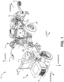
- FIG. 1 is a perspective view of ground surface modifying system 10, which can be configured as a line striping system for applying paint to ground surfaces.
- Ground surface modifying system 10 includes ground surface modifying machine 12 and driver 14.
- Machine 12 includes steering mechanism 16 and wheels 18A, 18B, 18C, which facilitate the movement of machine 12 along the ground. More specifically, the operator can control the direction of machine 12 with steering mechanism 16, and wheels 18A, 18B, 18C allow machine 12 to ride along the ground.
- steering mechanism 16 is a pair of handlebars, but in other embodiments, other mechanisms, such as a steering wheel, can be used.
- other embodiments of machine 12 can include fewer or more than three wheels.
- Machine 12 further includes reservoir 20, pump system 22, and dispenser 24.
- Reservoir 20 can be used to store paint or other materials.
- Pump system 22 can draw paint from reservoir 20 to spray or otherwise dispense from dispenser 24.
- Pump system 22 can be powered by a battery and operated by an electric motor, while dispenser 24 can be configured as a spray gun actuatable from steering mechanism 16 by, for example, a hand-controlled lever.
- pump system 22 can be powered by a liquid fuel engine, or a combination of a liquid fuel engine and hydraulic pump.
- system 10 could instead be used to apply other materials (e.g., beads, flowable solids, pellets, coatings, solvents, water, oil, etc.) to ground surfaces, or can be configured to modify ground surfaces in other ways.
- materials e.g., beads, flowable solids, pellets, coatings, solvents, water, oil, etc.
- Machine 12 does not propel itself, and does not include a motor for rotating any of the wheels 18A, 18B, 18C. Instead, machine 12 must be pushed. If driver 14 is unattached to machine 12, then the operator can walk behind machine 12 to push machine 12 forward, and pull machine 12 backward, using steering mechanism 16. However, machine 12 can be fatiguing to push and maneuver during the duration of the project. Driver 14 is useful for propelling machine 12 forwards and backwards. To that end, machine 12 can be attached/secured to driver 14 by hitch 26. Hitch 26 can be the single point of mechanical contact between machine 12 and driver 14. Hitch 26 allows machine 12 to articulate relative to driver 14, such as for turning, while also being pushed by driver 14.
- FIG. 2 is a perspective view of driver 14 shown isolated from machine 12.
- driver 14 further includes seat 28, wheels 34A, 34B, platform 36, pedals 38A, 38B, and interface panel 40.
- Seat 28 includes base portion 30 to support the weight of the operator, and upright back portion 32 to support the operator's back in a seated position.
- seat can be positioned, as shown, with base portion 30 generally parallel to the ground surface, and with upright back portion generally perpendicular to base portion 30. In other embodiments of driver 14, upright back portion 32 may not be present.
- Seat 28 can be formed from padded material, such as foam. From seat 28, the operator's hands can reach steering mechanism 16 of machine 12 to steer and control machine 12 while driver 14 transmits forward and/or backward propelling force to machine 12 through hitch 26.
- Wheels 34A, 34B can be inflated rubber tires, among other options. Although only two wheels 34A, 34B are shown, other embodiments of driver 14 can include a single wheel 34, or more than two wheels 34A, 34B (e.g., 34A, 34B, 34C, etc.). In the embodiment shown, driver 14 does not include any type of steering mechanism, such as a steering wheel or handle bars, for pivoting one of wheels 34A, 34B relative to the other to guide a turning maneuver. Rather, driver 14 relies on steering mechanism 16 of machine 12 to guide driver 14 through turning maneuvers while driver 14 pushes/pulls machine 12.
- steering mechanism 16 of machine 12 to guide driver 14 through turning maneuvers while driver 14 pushes/pulls machine 12.
- Platform 36 is positioned in front of and below seat 28. The operator may stand on platform 36 while mounting driver 14 or while resting during operation.
- Pedals 38A, 38B are mounted on either side of platform 36. Pedals 38A, 38B can be tilted forward and backward by the operator to control the movement of driver 14, as is discussed in greater detail below. Pedals 38-A, 38B can be mechanically linked to one another such that the tilting of one pedal causes the other to tilt as well.
- driver 14 is shown with two pedals 38A, 38B, other embodiments can include a single pedal 38 on either side of platform 36, or positioned elsewhere depending on the design of driver 14.
- Interface panel 40 operates various functions of driver 14. More specifically, interface panel 40 includes speed control switch 42 for turning on/off a speed control function of driver 14, and speed control input 44 for adjusting a forward speed setting, all of which is discussed in greater detail below.
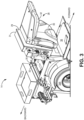
- FIG. 3 is a perspective view of driver 14 showing seat 28 tilted forward, which better illustrates seat mount 29, control box 31, battery bay 33, battery 35, and rotation point 37.
- seat 28 is mounted (on the side of base portion 30) on seat mount 29.
- Seat mount 29 is part of control box 31 that contains various control circuitry.
- Battery 35 can be, for example, a lead acid or lithium ion battery, and can be used to power the various functions of driver 14 discussed herein.
- seat 28 is titled forward at rotation point 37 near the forward end of seat 28, which can be configured as a movable fastener.
- rotation point 37 can be a bolt, rod, screw, hinge, etc.
- Seat 28 can additionally/alternatively be tilted to the rear or sides in other embodiments.
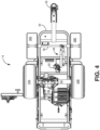
- FIG. 4 is a view of the underside of driver 14 further showing pedal axle 46, mechanical motion control 48, pedal tilt sensor 50, wheel axle 52, frame 54, motor 56, and transaxle 58.
- pedal axle 46 links pedals 38A, 38B.
- Pedal axle 46 can be a metal rod fixed to each of pedals 38A, 38B (e.g., using a clamping screw set) to transmit rotational motion from one pedal to the other.
- Mechanical motion control 48 is attached to pedal axle 46 and dampens motion of pedal axle 46 and thereby, the tilting motion of pedals 38A, 38B.
- Mechanical motion control 48 also transmits mechanical motion from pedal axle 46 to pedal tilt sensor 50, which measures the direction and degree of tilt of pedals 38A, 38B in order to determine the direction (i.e., forward or backward) and target speed of driver 14.
- Wheel axle 52 mechanically links wheels 34A, 34B, and is located below seat 28 and battery bay 33 (shown in FIG. 3 ).
- wheel axle 52 can be arranged in multiple segments to allow for differential rotation of wheels 34A, 34B, such as for turning maneuvers.
- Wheels 34A, 34B support frame 54, while frame 54 supports the other components, directly or indirectly, of driver 14.
- Transaxle 58 can include one or both of a transmission and differential in a single assembly, and can, for example, join the different segments of wheel axle 52.
- motor 56 is an electric motor, such as an alternating current induction motor having a rotor and stator, each with one or more solenoids.
- Another suitable electric motor 56 can be a brushed or brushless direct current motor also with a rotor and stator.
- motor 56 can be a gas-powered combustion motor.
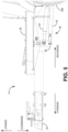
- FIG. 5 is a left side view of a portion of driver 14 forward of wheel 34B.
- pedal 38B is in a generally horizontal position, such that it is level with the ground, and also parallel with the top surface of platform 36.
- the horizontal position can correspond to a neutral position of driver 14, that is, a position that does not generate an input causing motor 56 to move driver 14 forward or backward, but rather to remain stationary or otherwise not accelerate.
- pedals 38A, 38B need not be perfectly horizontal to achieve a neutral setting, as is discussed in greater detail below. Tilting pedal 38B (and/or pedal 38A) such that the front end of pedal 38B moves downward while the back end moves upward equates to a forward tilt.
- Tilting pedal 38B (and/or pedal 38A) such that the front end of pedal 38B moves upward while the back end moves downward equates to a rearward (backward) tilt.
- the forward tilt and rearward tilt can cause a corresponding movement of driver 14, as is discussed in greater detail below.
- This manner of pedal tilting i.e., forward to move forward and rearward to move backward
- the operator's hands are typically placed on steering mechanism 16 ( FIG. 1 ), and are not usually available for speed control.
- Many ground striping projects involve equal amounts of driving in reverse and driving forward, particularly when striping parking lots where frequent forward and rearward motion is needed to paint the short lines of an array of parallel parking stalls.
- the operator can easily tilt either or both of pedals 38A, 38B forward and rearward using their feet to quickly and efficiently transition between forward and reverse propulsion.
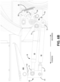
- FIGS. 6A-6C illustrate various components of mechanical motion control 48. More specifically, FIG. 6A is a perspective view of the underside of driver 14. FIGS. 6B and 6C are detailed left side and bottom views, respectively, of mechanical motion control 48.
- mechanical motion control 48 includes pedal arm 60, pedal link 62, and pedal dampener 64. As shown, pedal arm 60 is arranged as a plate attached at its top end 62 to pedal axle 46 with, for example, a collar and set screw. A forward tilt of pedals 38A, 38B causes bottom end 64 of pedal arm 60 to move backward, while a rearward tilt causes bottom end 64 to move forward.
- pedal dampener 68 can include an energy absorbing mechanism.
- such a mechanism can be housing 67 with two fluidly connected chambers 69A, 69B of variable volume (shown schematically in FIG. 7 ) filled with fluid with a narrow constriction between them. The two chambers 69A, 69B can alternately empty and fill based on the stretching and compression of dampener 68.
- Pedal dampener 68 is attached at its back end 76 to mounting plate 78, which is fixed to frame 54.
- back end 76 of pedal dampener 68 is also fixed, while front end 74 is movable as pedal arm 60 is moved by the tilting of pedals 38A, 38B.
- pedal dampener 68 can be stretched forward when the tilting of pedals 38A, 38B causes pedal arm 60 to move forward, and can be compressed when the tilting of pedals 38A, 38B causes pedal arm 60 to move backward.
- Pedal link 66 is attached at its back end 72 to plate 80.
- Plate 80 is pivotable with respect to mounting plate 78 by the forward and backward movement of pedal link 66 (via corresponding movement of bottom end 64 of pedal arm 60).
- Plate 80 includes tab 82.
- Tab 82 is positioned between first spring arm 84 and second spring arm 86, which are each connected to spring 88. Spring arms 84, 86 are pivotable with respect to mounting plate 78 through the movement of plate 80 and tab
- FIGS. 6A and 6B generally show tab 82 in a neutral position, as pedal 38B is also in a neutral position.
- Forward movement of pedal link 66 causes a corresponding movement of plate 80, which causes tab 82 to move downward from a neutral position to engage first spring arm 84.
- backward movement of pedal link 66 causes tab 82 to move upward from a neutral position to engage second spring arm 86.
- Movement of either first or second spring arm 84, 86 stretches spring 88.
- Tab 82 only engages one spring arm at a time from its upward or downward movement, and the stretching of spring pushes tab 82 back toward a neutral position.
- spring 88 can serve to place pedals 38A, 38B in the neutral position when no opposing pressure is applied from the operator's foot.
- FIG. 6C shows pedal tilt sensor 50 mounted to mounting plate 78.
- Pedal tilt sensor 50 measures the rotation of plate 80 (e.g., relative to the fixed position of pedal tilt sensor 50 and mounting plate78).
- Pedal tilt sensor 50 can be any type of sensor suitable for measuring rotation or change of position.
- pedal tilt sensor 50 is a potentiometer with a change in output based on rotation.
- pedal tilt sensor 50 can be an encoder or hall effect sensor measuring changes in position (e.g., angular position) corresponding to rotation of plate 80.
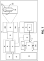
- FIG. 7 is a schematic diagram showing various components of driver 14. More specifically, FIG. 7 shows additional components of motor 56, drive shaft 57, speed sensor 59, and control circuitry 90. As shown, motor 56 includes stator 53 that at least partially surrounds rotor 55. Rotor 55 rotates driveshaft 57, which provides rotational motion to transaxle 58. Transaxle 58 rotates wheel axle 52 to rotate wheels 34A, 34B.
- Speed sensor 59 can be one or more sensors for measuring a speed of driver 14. As represented, speed sensor 59 measures rotation of driveshaft 57, although in other embodiments, speed sensor 59 can be configured to measure other components to indicate speed. Speed sensor 59 can alternatively be integrated into transaxle 58 in other embodiments. Speed sensor 59 can be arranged as a pair of encoders for measuring rotation of driveshaft 57 or other rotating part associated with transaxle 58. In such an embodiment, the measured rotating component(s) can include evenly-spaced bars or markings optically sensed by speed sensor 59 to determine a rotational velocity corresponding to the rotational velocity of wheels 34A, 34B and thereby, the speed of driver 14.
- speed sensor 59 can alternatively or additionally include one or more Hall effect sensors for indexing position of a cycle (e.g., rotation of driveshaft 57) for measuring the speed of driver 14.
- FIG. 7 further illustrates speed control switch 42, speed control input 44, pedal tilt sensor 50, and speed sensor 59 in communication with control circuitry 90.
- Control circuitry can include logic circuitry for executing the functions discussed herein.
- Control circuitry 90 can include hardware, firmware, and/or stored software. Control circuitry 90 can be entirely or partially mounted on one or more boards.
- Control circuitry 90 can include one or more microprocessors or other type of chip.
- control circuitry 90 includes processor 91 and memory 92.
- Memory 92 can store program instructions executable by processor 91 to carry out any of the functions referenced herein.
- Control circuitry 90 can output controlling signals to any of the electronic components of driver 14, such as motor 56.
- control circuitry 90 can increase or decrease driving power to motor 56 to accelerate or decelerate driver 14. It is noted that any driver 14 component may further include a separate microcontroller for managing its own operation.
- Battery (or batteries) 35 can be used to directly or indirectly power any of control circuitry 90, control switch 42, speed control input 44, pedal tilt sensor 50, motor 56, and/or speed sensor 59.
- driver 14 does not include a liquid fuel and/or combustion engine, and battery 35 is the only power source on driver 14.
- battery 35 can be plugged into a conventional electrical socket via a power cord (not shown) for recharging.
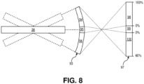
- FIG. 8 is a schematic diagram illustrating how pedal tilt is used to control operation of driver 14. Only a single pedal 38 is shown in FIG. 10 for simplicity, although as previously described, dual linked pedals 38A, 38B can be used.
- Pedal 38 is shown having three states: no-tilt, forward tilt, and rearward tilt.
- pedal 38 In the no-tilt state, pedal 38 can be in a generally horizontal position which is also the neutral/nominal position described above into which pedal 38 can be placed by the components of mechanical motion control 48 when no stepping force is applied to pedal 38 by the operator.
- Respective maximum forward and rearward tilt states are also indicated with dashed lines.
- Pedal 38 can tilt to various degrees between the three states. The degree of tilting or non-tilting of pedal 38 can be understood as the angle of the generally horizontal profile of pedal 38 with respect to the no-tilt (neutral) state.
- Each tilt state includes an angular range illustrated by tilt range chart 93. More specifically, tilt range chart 93 includes forward tilt range 96, neutral tilt range 95, and rearward tilt range 94.
- the ranges of chart 93 correspond continuously with the respective tilt state of pedal 38.
- a perfectly horizontal position of pedal 38 is not necessarily required to achieve the neutral/no-tilt state.
- neutral range 95 can be anywhere from 5, 10, or 20 degrees forward or backward from a horizontal (0 degree) position depending on the particular embodiment. This can be beneficial, for example, to allow operators of various sizes and/or with various biomechanics to select a suitable neutral position, and/or to provide a larger range to keep the operator from inadvertently entering either the forward or rearward tilt position.
- Forward tilt range 96 and rearward tilt range 94 can each correspond to a wider band than neutral tilt range 95. This allows for greater angular variation corresponding to different speeds.
- Rearward tilt range 94 can have the same angular distance as forward tilt range 96, but in some embodiments, may correspond to a smaller range of speed, as is discussed in greater detail below.
- Pedal tilt sensor 50 operates to provide continuous variation in each of forward tilt range 96 and rearward tilt range 94.
- pedal tilt sensor 50 is a potentiometer
- one or more electrical signals can be sent through an annular conductor having a resistance property.
- Rotation of pedal 38 can correspondingly move a wiper along the annular conductor to shorten or lengthen the distance along the annular conductor that the electrical signal must travel.
- the greater the travel distance along the annular conductor the greater the voltage drop measured between the wiper and the input of the annular conductor.
- the maximum of rearward tilt range 94 can correspond with a 1.0 V output signal
- the minimum of rearward tilt range 94 (corresponding to the maximum rearward tilt of neutral range 95) can correspond with a 4.5 V output signal.
- the minimum of forward tilt range 96 (corresponding to the maximum forward tilt of neutral range 95) can correspond with a 5.5 V output signal, and the maximum of forward tilt range 96 can correspond with a 9.0 V output signal.
- the output signals from pedal tilt sensor 50 can indicate the direction of tilt, forward or rearward, of pedal 38.
- the output signals can further indicate the degree of tilt continuously through each of rearward tilt range 94, neutral tilt range 95, and the forward tilt range 96.
- Tilt ranges 94, 95, 96 of pedal 38 correspond to speed ranges 100, 99, 98, respectively, as illustrated by speed range chart 97.
- the speed ranges can be adjusted based on speed targets (i.e., particular operating speeds corresponding to different degrees of tilt of pedal 38) as selected by the operator.
- increasing forward tilt of pedal 38 through forward tilt range 96 can proportionally increase the forward speed through forward speed range 98.
- Decreasing forward tilt through forward tilt range 96 can proportionally decrease the forward speed through forward speed range 98.
- Increasing rearward tilt through rearward tilt range 94 can proportionally increase the reverse speed through rearward speed range 100.
- Decreasing rearward tilt through rearward tilt range 94 can proportionally decrease the reverse speed through rearward speed range 100.
- the maximum extent of forward tilt range 96 can correspond with a 100% output of motor 56 (e.g., motor 56 is driven at its maximum setting in a rotational direction corresponding to forward motion of driver 14).
- a tilt position corresponding to the middle of forward tilt range would correspondingly result in a 50% output of motor 56.
- pedal 38 tilt can be mapped to a selected speed target of driver 14.
- the maximum extent of forward tilt range 96 can correspond to a speed target of 10 miles ( ⁇ 16 kilometers) per hour in a forward direction, while a middle tilt position (50% output) can correspond to a speed target of 5 miles ( ⁇ 8 kilometers) per hour.
- All of neutral range 99 can correspond to a 0% output of motor 56 or a stationary (0 miles/kilometers per hour) speed target with no forward or rearward movement of driver 14.
- the maximum extent of rearward tilt range 94 can correspond with a -60% output of motor 56 (i.e., motor 56 is driven at 60% its maximum setting in a rotational direction corresponding to the rearward direction of driver 14). If using a speed target instead, -60% output of motor 56 corresponds to a reverse speed of 6 miles (-9.6 kilometers) per hour.
- forward speed range 98 can be 0 to 10 miles (0 to -16 kilometers) per hour
- rearward speed range 100 can be 0 to 6 miles (0 to -9.6 kilometers) per hour.
- forward tilt range 96 and rearward tilt range 94 can have equivalent angular distances, such that pedal 38 rotates the same angular distance when traveling through forward tilt range 96 as it does when travelling through rearward tilt range 94.
- rearward tilt range 94 can have a smaller angular distance than forward tilt range 96. For example, if rearward speed range 100 reaches a maximum (output or speed) that is 60% of the maximum of forward speed range 98, then rearward tilt range 94 can accordingly be adjusted to be 60% of the angular distance of forward tilt range 96.
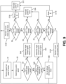
- FIG. 9 is a flowchart illustrating the process of controlling output of motor 56 based on sensor inputs. More specifically, FIG. 9 represents an algorithm used to achieve and maintain a targeted speed or motor output.
- a signal is received from pedal tilt sensor 50.
- processor 91 of control circuitry 90 can receive the signal.
- a current speed of driver 14 is determined. This can include receiving a signal from speed sensor 59 to determine the current speed of driver 14.
- a multiplier coefficient can be used to proportionally relate the speed of driver 14 with the rotational speed of driveshaft 57 (or other rotating component) as determined by speed sensor 59.
- step S3 it is determined whether the signal received from pedal tilt sensor 50 indicated that pedal 38 is in forward tilt range 96. If it is determined that pedal 38 is not in forward tilt range, then step S4B determines whether pedal 38 is in rearward tilt range 94. If pedal 38 is not in rearward tilt range 94, then it can be concluded that pedal 38 is in neutral range 95, indicating that the operator is not electing to propel driver 14. As a result, at step S5B, driving power is stopped or otherwise not delivered to motor 56.
- step S4A determines the target forward speed based on the signal received from pedal tilt sensor 50. This can include translating the angle, signal voltage, or other indicator of tilt degree to forward speed range 98 of speed range chart 97. Determining target forward speed can further include using an algorithm or lookup table to determine a target forward speed based on the degree of tilt of pedal 38, wherein such algorithm or lookup table outputs higher forward target speed for greater forward tilt, and lesser forward target speed for lesser forward tilt, for continuous ranges of pedal 38 tilt and target speeds.
- step S6 determines whether the current speed (determined at step S2) is less than the target forward speed determined at step S4A. If the current speed is less than the target forward speed, the process advances to step S9A to increase driving power to motor 56. Increasing the driving power can correspond to increasing the power beyond the current amount of driving power delivery. Step S9A can include engaging in an acceleration profile to gradually increase driving power over the course of one, two, three, or four or more seconds to avoid aggressive acceleration. If the check in step S6 determines that the current speed is not less than the target forward speed, then the process advances to step S8. At step S8, a comparison is performed to determine whether the current speed (as determined at step S2) is greater than the target forward speed. If the current speed is not greater than the target forward speed, then the process ultimately advances to step S 1 or other step restarting the iteration, and motor 56 driving power is not increased or decreased.
- step S 8 the process advances to step S 10A in which a brake (B) is applied.
- Brake B is intended to slow driver 14 toward the current targeted forward speed.
- Brake B can represent a regenerative braking method such as allowing rotor 55 to free spin in stator 53. This generates electrical energy which can be routed to battery 35 for recharging.
- brake B can represent an active braking method. For example, physically moving motor 56 components to realign the phases of stator 53 and rotor 55 can alter motor performance and have a braking effect.
- a solenoid could also be used to engage/disengage a braking feature of motor 56 forcing cogs to engage and alter motor rotation.
- Brake B can involve a mechanical braking method that frictionally engages drive shaft 57, a component of transaxle 58, wheel axle 52, and/or one or both of wheels 34A, 34B.
- step S5A determines the target reverse speed based on the signal received from pedal tilt sensor 50.
- Determining the target reverse speed can include translating the angle, signal voltage, or other indicator of tilt degree to rearward speed range 100 of speed range chart 97.
- Determining target reverse speed can further include using an algorithm or lookup table to determine a target reverse speed based on the degree of tilt of pedal 38, wherein such algorithm or lookup table outputs higher rearward target speed for greater rearward tilt, and lesser rearward target speed for lesser rearward tilt, for continuous ranges of pedal 38 tilt and target speeds.
- step S7 determines whether the current speed (determined at step S2) is less than the target rearward speed determined at step S5A. If the current speed is not less than the target rearward speed, then the process advances to step S9B. At step S9B, it is determined whether the current speed is greater than the target rearward speed. If the current speed is not greater than the target rearward speed, then it is assumed that the current speed matches the target rearward speed, and the process advances to step S11B to maintain the current power output the motor 56. After step S 11B, the process returns to step S1 (or another step) for another iteration of the loop.
- step S9B If, at step S9B, the check determines the current speed is greater than the target rearward speed, then the process advances to step S11A to brake.
- Braking in step S11A can be the same as the braking of step S10A, except that in step S11A, the goal is to decelerate rearward instead of decelerating forward movement.
- step S 12 The process advances to step S 12 from either step S 10A or step S 11B.
- step S 12 driving power to motor 56 is reduced.
- step S12 the process returns to step S1 (or another step) for another iteration of the loop.
- steps S11A and step S12 can be reversed and/or the steps can be performed in several alternating phases of braking and motor 56 driving power decreasing in various other embodiments.
- step S7 if the check determines that the current speed is less than the target rearward speed, the process advances to step S9A at which driving power to motor 56 is increased.
- FIG. 9 is one version of demonstrating various steps, and that one or more can be eliminated, substituted, added, or otherwise changed or integrated into other processes.
- one or both braking steps S10A, S 11A can be omitted and driver 14 instead allowed to coast to slow down.
- FIG. 10 is a flow chart illustrating a process for engaging a speed control feature of driver 14.
- maintaining a constant speed of the ground surface modifying machine 12 can be important.
- absolute speed is more important than the drive power of motor 56 because changing conditions, such as a hill, can change the speed of driver 14 despite consistent drive power to motor 56. Therefore, closed loop speed control is desired. Assuming that pump system 22 outputs consistent volume of paint from dispenser 24, a constant speed should form stripes of even thickness.
- FIG. 10 demonstrates a speed control feature to help driver 14 repeatedly reach and maintain a consistent speed despite intervening forward-backward maneuvering of the ground surface modifying system 10 between each stripe.
- the process of FIG. 10 includes operating driver 14 within a nominal foot pedal map.
- the nominal foot pedal map can be a standard (e.g., full range, linear) correspondence between pedal 38 tilt and targeted speed of motor 56, such as that demonstrated in FIG. 8 .
- the process includes a check in step S 101 which determines whether a constant speed mode has been engaged.
- the constant speed mode can be engaged when speed control switch 42 is actuated to an ON state. If speed control switch 42 is not actuated to the ON state, then the process advances to step S 102B to operate driver 14 within the nominal foot pedal map. If, instead, speed control switch 42 is actuated to the ON state, then the process advances to step S 102A.
- control circuitry 90 receives a forward speed set point.
- the forward speed set point can be received from speed control input 44.
- Speed control input 44 can be a knob linked with a potentiometer, a digital input, or other type of input for indicating a forward speed set point.
- the forward speed set point can serve as a temporary maximum forward speed as further shown.
- the forward speed set point can be less than the maximum forward speed that driver 14 is capable of achieving in the nominal foot pedal map, and can be less than the 100% speed indicated in FIG. 10 .
- speed control input 44 can be a potentiometer able to indicate a range of speeds.
- speed control input 44 can be set at a particular level (e.g., the forward speed set point) despite forward and reverse commands and corresponding actions as input through pedal 38. Therefore, pedal 38 can be used to move driver 14 forward and rearward during maneuvering when not spraying a ground stripe, but the forward speed set point can be used whenever spraying a ground stripe so that spraying can be carried out at a consistent speed for every stripe painted.
- control circuitry 90 drives motor 56 at the set speed as long as pedal 38 is tilted to or past some degree of forward tilt range 94. The operator can then tilt pedal 38 forward within forward tilt range 94, such as to its maximum forward tilt. In this state, driver 14 will not be propelled forward, or will be propelled at a very low speed, because speed control input 44 was set to the lowest speed, which may be zero.
- the operator can then slowly increase the level of speed control input 44, corresponding to an increasing forward speed set point, during which time control circuitry 90 recognizes that the target speed is greater than the current speed, and will cause motor 56 to accelerate driver 14 forward.
- the operator can continue to increase the level of the forward speed set point using speed control input 44 until driver 14 is moving at a desired speed.
- the operator can stop manipulating speed control input 44 (i.e., leave speed control input 44 at the setting that achieved the desired speed).
- Driver 14 can subsequently achieve and maintain the speed corresponding to the forward speed set point if a particular input is received from pedal tilt sensor 50 indicating that pedal 38 has been pushed to or past the forward speed set point along forward tilt range 94, as further discussed herein.
- step S103 control circuitry 90 remaps the forward tilt profile of pedal 38 with the current forward speed set point of speed control input 44 serving as the maximum forward speed allowed by actuation of pedal 38 while the constant speed mode is engaged (or until speed control input 44 indicates a different forward speed set point level).
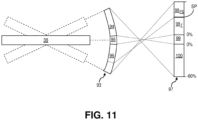
- step S104 operates driver 14 with the remapped pedal control. The remapping of the pedal control is illustrated in FIGS. 11 and 12 .
- FIG. 11 is similar to FIG. 8 , but schematically illustrates the remapping of forward speed range 98 based on forward speed set point SP, as previously described.
- forward speed set point SP corresponds with a lesser speed than what would other have been the maximum speed of the forward speed range (e.g., under the nominal foot pedal map).
- Truncated forward speed range 98 T is the same as the corresponding lower speed portion of the original forward speed range 98 and has continuous speed control, such that increasing forward tilt of pedal 38 through truncated forward speed range 98 T corresponds with increasing target speed to the same amount as the nominal foot pedal map.
- truncated forward speed range 98 T can span from 0 miles per hour to 7 miles (-11.3 kilometers) per hour. Other forward speed set points are contemplated herein. As another example, truncated forward speed range 98 T can span 0% to 70% of maximum engine output.
- Forward speed set point range 98 FS represents a range that has the same target speed throughout, specifically the forward speed set point. As pedal 38 is tilted forward into and through forward speed set point range 98 FS , the target speed does not change and continues to be the speed of the current forward speed set point. In this regard, setting the forward speed set point SP creates a forward speed set point range 98 FS of forward tilt that the operator can move pedal 38 into and through without deviating from the speed of the forward speed set point.
- the advantage of having forward speed set point range 98 FS correspond with a single forward speed is that the operator does not need to finesse the particular angle of pedal 38 to achieve the targeted speed of the forward speed set point when applying stripe after stripe.
- the operator can just move pedal 38 anywhere into forward speed set point range 98 FS and achieve the same speed.
- the operator can simply push (or otherwise move) pedal 38 to its maximum forward tilt to achieve targeted speed of the forward speed set point for spraying a consistent stripe, over and over, as necessary.
- forward speed set point range 98 FS such "jamming" of pedal 38 would command driver 14 to move at its fastest possible speed, which may not be desirable for certain striping operations.
- FIG. 12 demonstrates another option for remapping the pedal control.
- the operation of the system shown in FIG. 12 is similar to that of FIGS. 8 and 11 , except as otherwise noted.
- the forward speed set point SP is always at the maximum degree of forward tilt of pedal 38, with the rest of forward speed range 98 R being scaled to go from zero at its lowest end up to the level of the forward speed set point SP.
- the full range of forward tilt through forward speed range 98 R is still available to the operator for continuous speed adjustment while maneuvering, but is rescaled through the range being that the maximum speed is now lower.
- remapped forward speed range 98 R For example, if the forward speed set point SP is 7 miles (-11.3 kilometers) per hour or 70% output, then the full travel of remapped forward speed range 98 R will be 0 miles per hour to 7 miles per hour, or 0% to 70% output (instead of 0-10 miles per hour or 0-100% ranges without the speed control feature engaged or in the nominal pedal map). In this example, moving pedal 38 from neutral through the entire remapped forward speed range 98 R will continuously increase the target speed from 0 to 7 miles per hour until pedal 38 reaches the maximum forward tilt position, at which point the speed will remain at 7 miles per hour.
- neutral speed range 99 and rearward speed range 100 are not truncated or otherwise remapped.
- various speed control features discussed above allow the operator to achieve a continuous speed of driver 14 when pedal 38 is tilted to or past a threshold degree within a set range. In this regard, the operator must maintain the threshold degree of tilt to maintain continuous speed. This differs from other equipment/vehicles which may allow an operator to achieve a speed set point, then remove physical contact (e.g., hands or feet) from the controls.
Landscapes
- Engineering & Computer Science (AREA)
- Mechanical Engineering (AREA)
- Transportation (AREA)
- Chemical & Material Sciences (AREA)
- Combustion & Propulsion (AREA)
- Power Engineering (AREA)
- Life Sciences & Earth Sciences (AREA)
- Sustainable Development (AREA)
- Sustainable Energy (AREA)
- Civil Engineering (AREA)
- Structural Engineering (AREA)
- Architecture (AREA)
- Electric Propulsion And Braking For Vehicles (AREA)
- Mechanical Control Devices (AREA)
- Motorcycle And Bicycle Frame (AREA)
Claims (14)
- Batteriebetriebener Antrieb (14) zum Antreiben einer mit Rädern versehenen Bodenoberflächenmodifizierungsmaschine (12), wobei der Antrieb umfasst:mindestens ein Rad (34A, B), das eine Bodenoberfläche berührt;einen batteriebetriebenen Elektromotor (56);mindestens ein Pedal (38A, B), das durch einen Bereich hindurch betätigt werden kann; undmindestens einen Pedalsensor (50), der dafür konfiguriert ist, ein oder mehrere Signale auszugeben, die einen Grad der Betätigung des mindestens einen Pedals innerhalb des Bereichs angeben;einen Geschwindigkeitssteuereingang (44) zum Eingeben eines konstanten Geschwindigkeitsniveaus; undeine Steuerschaltung (31), die dafür konfiguriert ist, das eine oder die mehreren Signale zu empfangen, das konstante Geschwindigkeitsniveau zu empfangen und die Zufuhr von elektrischer Batterieleistung zu dem Elektromotor zu steuern, um eine Geschwindigkeit des Antriebs zu steuern;wobei die Steuerschaltung des Weiteren konfiguriert ist zum:Steuern des Elektromotors, um den Antrieb vorwärts zu beschleunigen, auf der Grundlage des einen oder der mehreren Signale, die eine Betätigung des Pedals innerhalb eines ersten Abschnitts des Bereichs angeben, wobei die dem Elektromotor zugeführte Leistung zur Vorwärtsbeschleunigung proportional zum Grad der Betätigung des mindestens einen Pedals durch den ersten Abschnitt des Bereichs hindurch ist, dergestalt, dass die Geschwindigkeit des Antriebs auf der Grundlage des Grades der Betätigung des Pedals innerhalb des ersten Abschnitts des Bereichs variabel ist; unddadurch gekennzeichnet, dass die Steuerschaltung des Weiteren konfiguriert ist zum:
Steuern des Elektromotors, um den Antrieb auf der Grundlage des einen oder der mehreren Signale, die eine Betätigung des Pedals zu einem zweiten Abschnitt des Bereichs angeben, vorwärts auf das konstante Geschwindigkeitsniveau zu beschleunigen, wobei sich der zweite Abschnitt des Bereichs von dem ersten Abschnitt des Bereichs unterscheidet und der zweite Abschnitt des Bereichs einer weiteren Betätigung des mindestens einen Pedals in Bezug auf den ersten Abschnitt des Bereichs entspricht. - Antrieb (14) nach Anspruch 1, wobei das konstante Geschwindigkeitsniveau eine Bedienereingabe ist, die eine zuvor festgelegte konstante Geschwindigkeit angibt, und wobei die Steuerschaltung (31) dafür konfiguriert ist, die Bedienereingabe, die die zuvor festgelegte konstante Geschwindigkeit angibt, zu empfangen.
- Antrieb (14) nach Anspruch 1 oder 2, wobei die Steuerschaltung (31) dafür konfiguriert ist, die zuvor festgelegte konstante Geschwindigkeit von einem Geschwindigkeitssensor (59) zu empfangen, der die Geschwindigkeit des Antriebs misst, wenn der Geschwindigkeitssteuereingang (44) betätigt wird.
- Antrieb (14) nach einem der vorangehenden Ansprüche, wobei die Steuerschaltung (31) dafür konfiguriert ist, die Bedienereingabe, die die zuvor festgelegte konstante Geschwindigkeit angibt, von dem mindestens einen Pedalsensor (50), der den Grad der Betätigung des mindestens einen Pedals (38A, B) innerhalb des Bereichs angibt, zu empfangen.
- Antrieb (14) nach einem der vorangehenden Ansprüche, wobei die Steuerschaltung (31) dafür konfiguriert ist, zu arbeiten in:einem ersten Modus, in dem die dem Elektromotor (56) zur Vorwärtsbeschleunigung zugeführte Leistung proportional zum Grad der Betätigung des mindestens einen Pedals (38A, B) durch den ersten Abschnitt des Bereichs und den zweiten Abschnitt des Bereichs hindurch ist, dergestalt, dass die Geschwindigkeit des Antriebs auf der Grundlage des Grades der Betätigung des mindestens einen Pedals durch den ersten Abschnitt des Bereichs und den zweiten Abschnitt des Bereichs hindurch variabel ist; undeinem zweiten Modus, in dem die dem Elektromotor zur Vorwärtsbeschleunigung zugeführte Leistung proportional zum Grad der Betätigung des mindestens einen Pedals durch den ersten Abschnitt des Bereichs, aber nicht durch den zweiten Abschnitt des Bereichs hindurch ist, dergestalt, dass die Geschwindigkeit des Antriebs auf der Grundlage des Grades der Betätigung des mindestens einen Pedals innerhalb des ersten Abschnitts des Bereichs variabel ist, während die Steuerschaltung den Bediener veranlasst, die zuvor festgelegte konstante Geschwindigkeit beizubehalten, wenn das mindestens eine Pedal bis in den zweiten Abschnitt des Bereichs hinein betätigt wird.
- Antrieb (14) nach Anspruch 5, wobei der erste Abschnitt des Bereichs denselben Bereich variabler Geschwindigkeiten im ersten Modus und im zweiten Modus darstellt.
- Antrieb (14) nach Anspruch 5 oder 6, wobei beim Übergang zu dem zweiten Modus die Steuerschaltung (31) den ersten Abschnitt des Bereichs neu abbildet, um einen anderen Bereich variabler Geschwindigkeiten im Vergleich zum ersten Abschnitt des Bereichs im ersten Modus darzustellen.
- Antrieb (14) nach einem der Ansprüche 5, 6 oder 7, wobei der Bereich variabler Geschwindigkeiten, auf die der Antrieb gemäß dem Management durch die Steuerschaltung (31) beschleunigt wird, proportional zum Grad der Betätigung des mindestens einen Pedals (38A, B) durch den ersten Abschnitt des Bereichs hindurch ist, aber nicht proportional von dem ersten Abschnitt des Bereichs zu dem zweiten Abschnitt des Bereichs ist.
- Antrieb (14) nach einem der vorangehenden Ansprüche, wobei das mindestens eine Pedal (38A, B) dadurch betätigt werden kann, dass es durch einen Winkelbereich hindurch neigbar ist, und der mindestens eine Pedalsensor (50) dafür konfiguriert ist, das eine oder die mehreren Signale auf der Grundlage eines Grades der Vorwärtsneigung des mindestens einen Pedals auszugeben.
- Antrieb (14) nach einem der vorangehenden Ansprüche, der des Weiteren umfasst:
einen Geschwindigkeitssensor (59), der dafür konfiguriert ist, ein Signal auszugeben, das eine gemessene Augenblicksgeschwindigkeit des Antriebs angibt. - Antrieb (14) nach Anspruch 10, wobei die Steuerschaltung (31) des Weiteren konfiguriert ist zum:Bestimmen einer Soll-Vorwärtsgeschwindigkeit auf der Grundlage eines Betrages der Vorwärtsneigung des mindestens einen Pedals (38A, B), der durch das eine oder die mehreren Signale des Pedalsensors (50) angegeben wird;Erhöhen des Zuführens von Antriebsleistung zu dem Elektromotor (56), wenn die Soll-Vorwärtsgeschwindigkeit größer ist als die Augenblicksgeschwindigkeit des Antriebs, die durch das Signal des Geschwindigkeitssensors (59) angegeben wird; undVerringern des Zuführens von Antriebsleistung zu dem Elektromotor, wenn die Soll-Vorwärtsgeschwindigkeit kleiner ist als die Augenblicksgeschwindigkeit des Antriebs, die durch das Signal des Geschwindigkeitssensors angegeben wird.
- Antrieb (14) nach Anspruch 10 oder 11, wobei die Steuerschaltung (31) des Weiteren konfiguriert ist zum:Bestimmen einer Soll-Rückwärtsgeschwindigkeit auf der Grundlage eines Betrages der Rückwärtsneigung des mindestens einen Pedals (38A, B), der durch das eine oder die mehreren Signale des Pedalsensors (50) angegeben wird;Erhöhen des Zuführens von Antriebsleistung zu dem Elektromotor (56), wenn die Soll-Rückwärtsgeschwindigkeit größer ist als die Augenblicksgeschwindigkeit des Antriebs, die durch das Signal des Geschwindigkeitssensors (59) angegeben wird; undVerringern des Zuführens von Antriebsleistung zu dem Elektromotor, wenn die Soll-Rückwärtsgeschwindigkeit kleiner ist als die Augenblicksgeschwindigkeit des Antriebs, die durch das Signal des Geschwindigkeitssensors angegeben wird.
- Verfahren zum Betreiben eines batteriebetriebenen Antriebs (14) einer Bodenoberflächenmodifizierungsmaschine (12) nach einem der vorangehenden Ansprüche in einem Geschwindigkeitssteuermodus, wobei das Verfahren umfasst:Aktivieren des Geschwindigkeitssteuermodus;Auswählen eines Vorwärtsgeschwindigkeits-Sollwertes unter Verwendung eines Geschwindigkeitssteuereingangs (44) ;Betätigen eines Pedals (38A, B) des Antriebs in einer Vorwärtsrichtung in einen Vorwärtswinkelbereich hinein;Betätigen des Pedals durch einen Vorwärtsgeschwindigkeitsbereich hindurch, der mit dem Vorwärtswinkelbereich verknüpft ist, um den Antrieb vorwärts zu beschleunigen, wobei die dem Elektromotor (56) zugeführte Leistung zur Vorwärtsbeschleunigung proportional zu einem Grad der Betätigung des Pedals innerhalb des Vorwärtsgeschwindigkeitsbereichs ist;und gekennzeichnet durchBetätigen des Pedals zu einem Winkelgradbereich, der mit dem Vorwärtsgeschwindigkeits-Sollwert verknüpft ist, wobei der Vorwärtsgeschwindigkeits-Sollwert eine konstante Vorwärtsgeschwindigkeit des Antriebs im Geschwindigkeitssteuermodus darstellt.
- Verfahren nach Anspruch 13, wobei:
ein Neigen des Pedals (38A, B) durch den Vorwärtsgeschwindigkeits-Sollwertbereich hindurch nicht die Geschwindigkeit des Antriebs ändert.
Applications Claiming Priority (2)
| Application Number | Priority Date | Filing Date | Title |
|---|---|---|---|
| US201862771704P | 2018-11-27 | 2018-11-27 | |
| EP19211777.8A EP3660216B1 (de) | 2018-11-27 | 2019-11-27 | Elektrischer antrieb für eine bodenoberflächenmodifizierungsmaschine auf rädern |
Related Parent Applications (2)
| Application Number | Title | Priority Date | Filing Date |
|---|---|---|---|
| EP19211777.8A Division EP3660216B1 (de) | 2018-11-27 | 2019-11-27 | Elektrischer antrieb für eine bodenoberflächenmodifizierungsmaschine auf rädern |
| EP19211777.8A Division-Into EP3660216B1 (de) | 2018-11-27 | 2019-11-27 | Elektrischer antrieb für eine bodenoberflächenmodifizierungsmaschine auf rädern |
Publications (2)
| Publication Number | Publication Date |
|---|---|
| EP4101983A1 EP4101983A1 (de) | 2022-12-14 |
| EP4101983B1 true EP4101983B1 (de) | 2024-06-12 |
Family
ID=68699309
Family Applications (2)
| Application Number | Title | Priority Date | Filing Date |
|---|---|---|---|
| EP19211777.8A Active EP3660216B1 (de) | 2018-11-27 | 2019-11-27 | Elektrischer antrieb für eine bodenoberflächenmodifizierungsmaschine auf rädern |
| EP22180206.9A Active EP4101983B1 (de) | 2018-11-27 | 2019-11-27 | Elektrischer antrieb für eine bodenoberflächenmodifizierungsmaschine auf rädern |
Family Applications Before (1)
| Application Number | Title | Priority Date | Filing Date |
|---|---|---|---|
| EP19211777.8A Active EP3660216B1 (de) | 2018-11-27 | 2019-11-27 | Elektrischer antrieb für eine bodenoberflächenmodifizierungsmaschine auf rädern |
Country Status (4)
| Country | Link |
|---|---|
| US (3) | US11518253B2 (de) |
| EP (2) | EP3660216B1 (de) |
| CN (2) | CN117584768A (de) |
| AU (2) | AU2019271894B2 (de) |
Families Citing this family (3)
| Publication number | Priority date | Publication date | Assignee | Title |
|---|---|---|---|---|
| CN112921780A (zh) * | 2021-03-02 | 2021-06-08 | 武汉理工大学 | 一种智能化二维交通标线喷涂装置 |
| CN114771712B (zh) * | 2021-07-20 | 2024-06-18 | 苏州昊维工业产品设计有限公司 | 车辆脚踏组件及电动车 |
| JP2023178908A (ja) * | 2022-06-06 | 2023-12-18 | 株式会社 神崎高級工機製作所 | 電動作業車両 |
Family Cites Families (35)
| Publication number | Priority date | Publication date | Assignee | Title |
|---|---|---|---|---|
| US2511692A (en) | 1945-08-06 | 1950-06-13 | Deere & Co | Tractor and steerable support therefor |
| US2895279A (en) | 1955-11-10 | 1959-07-21 | G D Shawver | Sectional vehicle |
| US2867449A (en) | 1957-10-14 | 1959-01-06 | Francis B Shawver | Hand cart adapted for use with interchangeable load carriers |
| US3161994A (en) | 1961-07-11 | 1964-12-22 | Jr Jacob Neitzer | Self-propelled riding attachment for an implement |
| US4077731A (en) | 1975-02-18 | 1978-03-07 | Orville H. Holz, Jr. | Reinforcing wire laying machines and attachments |
| US3995569A (en) | 1975-03-28 | 1976-12-07 | Picardat Robert N | Two part lawn treating machine |
| GB2195301B (en) | 1986-09-23 | 1990-08-01 | Raymond Joseph Parker | Motorised adaptor unit for manually propelled vehicles |
| US4771840A (en) | 1987-04-15 | 1988-09-20 | Orthokinetics, Inc. | Articulated power-driven shopping cart |
| US5033564A (en) | 1990-02-20 | 1991-07-23 | Floor Style Products, Inc. | Power riding trailer for an implement |
| US5114268A (en) | 1991-01-18 | 1992-05-19 | Mac Stripers, Inc. | Apparatus for applying a traffic stripe to a road |
| US5511631A (en) * | 1993-05-20 | 1996-04-30 | Kubota Corporation | Running control structure for a lawn tractor |
| US5718534A (en) | 1996-03-13 | 1998-02-17 | Fine Line Plastics Corp. | Rear drive ride-on tractor unit for propelling steerable utility vehicles such as walk-behind paint stripers |
| US6474427B1 (en) | 1999-04-16 | 2002-11-05 | James William Tunnecliff | Wheeled device with different operational modes |
| US6357232B1 (en) * | 1999-12-15 | 2002-03-19 | Caterpillar Inc. | Differential pedal interface system for a cycling type work machine |
| US6575819B2 (en) | 2000-01-27 | 2003-06-10 | Kurt Beyersdorff | Floor accessory driver |
| US20050115760A1 (en) * | 2001-10-19 | 2005-06-02 | Sprinkle David L. | Speed control for utility vehicle operable from rearward-facing seat |
| US6986397B2 (en) | 2002-03-01 | 2006-01-17 | Floorstyle Products, Inc. | Power riding trailer for an implement |
| US6845829B2 (en) * | 2002-04-04 | 2005-01-25 | James T. Hafendorfer | Utility vehicle with foot-controlled mobility |
| US7032694B2 (en) | 2003-06-24 | 2006-04-25 | Jessen Thomas F | Propulsion sulky |
| US20080106112A1 (en) * | 2005-12-28 | 2008-05-08 | Yanmar Co., Ltd. | Tractor |
| US20120159916A1 (en) * | 2007-01-15 | 2012-06-28 | Kanzaki Kokyukoki Manufacturing Co., Ltd. | Control sysytem for motor-driven lawnmower vehicle |
| EP1943894B1 (de) * | 2007-01-15 | 2010-05-19 | Kanzaki Kokyukoki Mfg. Co., Ltd. | Rasenmäher |
| US7735587B1 (en) | 2008-02-08 | 2010-06-15 | Stahlnecker Todd D | Hand truck driving apparatus |
| US8386131B2 (en) * | 2009-07-27 | 2013-02-26 | Caterpillar Inc. | Method and system for controlling a driving direction of an electric drive machine |
| US9226444B2 (en) | 2011-07-14 | 2016-01-05 | Husqvarna Ab | Battery powered lawn care vehicle with efficient drive controller |
| US20150134148A1 (en) * | 2012-05-03 | 2015-05-14 | Nss Enterprises, Inc. | Floor cleaning or burnishing machine with pointing devices |
| US20140064849A1 (en) | 2012-08-28 | 2014-03-06 | Ralph Arnold | Multi-mode tape-applying striping machine and methods |
| US20150328994A1 (en) * | 2014-05-13 | 2015-11-19 | Razor Usa Llc | Kart |
| FR3021023B1 (fr) * | 2014-05-14 | 2016-07-01 | Aissam Moujoud | Vehicule personnel conduisible avec les pieds |
| CN104014123A (zh) * | 2014-06-13 | 2014-09-03 | 杭州骑客智能科技有限公司 | 纵向双轮车体 |
| US10252724B2 (en) * | 2015-09-24 | 2019-04-09 | P&N Phc, Llc | Portable two-wheeled self-balancing personal transport vehicle |
| CN107604803A (zh) * | 2017-09-28 | 2018-01-19 | 南通威而多专用汽车制造有限公司 | 具有照明功能的划线机助推器 |
| US10561064B2 (en) * | 2017-11-03 | 2020-02-18 | Venture Products, Inc. | Hydraulically controlled flip up mower deck |
| US10442292B2 (en) * | 2017-12-14 | 2019-10-15 | Schiller Grounds Care, Inc. | System for infinitely variable speed control |
| CN118160211A (zh) * | 2021-10-15 | 2024-06-07 | 南京泉峰科技有限公司 | 骑乘式割草机 |
-
2019
- 2019-11-20 US US16/689,829 patent/US11518253B2/en active Active
- 2019-11-25 AU AU2019271894A patent/AU2019271894B2/en active Active
- 2019-11-26 CN CN202410028330.5A patent/CN117584768A/zh active Pending
- 2019-11-26 CN CN201911174214.XA patent/CN111216565B/zh active Active
- 2019-11-27 EP EP19211777.8A patent/EP3660216B1/de active Active
- 2019-11-27 EP EP22180206.9A patent/EP4101983B1/de active Active
-
2022
- 2022-11-04 US US17/980,738 patent/US12533961B2/en active Active
-
2024
- 2024-12-19 AU AU2024278640A patent/AU2024278640A1/en active Pending
-
2025
- 2025-06-25 US US19/249,216 patent/US20250319776A1/en active Pending
Also Published As
| Publication number | Publication date |
|---|---|
| AU2019271894B2 (en) | 2024-10-10 |
| US11518253B2 (en) | 2022-12-06 |
| US12533961B2 (en) | 2026-01-27 |
| AU2024278640A1 (en) | 2025-01-16 |
| CN111216565A (zh) | 2020-06-02 |
| AU2019271894A1 (en) | 2020-06-11 |
| CN111216565B (zh) | 2024-01-23 |
| EP4101983A1 (de) | 2022-12-14 |
| EP3660216B1 (de) | 2022-08-03 |
| US20230059159A1 (en) | 2023-02-23 |
| US20250319776A1 (en) | 2025-10-16 |
| CN117584768A (zh) | 2024-02-23 |
| EP3660216A1 (de) | 2020-06-03 |
| US20200164752A1 (en) | 2020-05-28 |
Similar Documents
| Publication | Publication Date | Title |
|---|---|---|
| US12533961B2 (en) | Electric driver for wheeled ground surface modifying machine | |
| US12575485B2 (en) | Grounds maintenance vehicle with traction and steering control system | |
| EP2844120B1 (de) | Bodenreiniger mit doppelantrieb | |
| US9238477B2 (en) | Method and system for a lift device having independently steerable wheels | |
| KR20180079429A (ko) | 수직 장애물을 가로지르는 시스템 및 방법 | |
| KR102071866B1 (ko) | 듀얼구동 제어 및 3축 제어를 이용한 자동 차선도장장치 | |
| CN104594161B (zh) | 轮胎摊铺机及其行走控制系统 | |
| CN101992799B (zh) | 摇杆控制双侧轮组独立驱动的工程车辆 | |
| AU2005225047A1 (en) | Pallet truck tiller arm with angular speed mode adjustment and acceleration control | |
| KR101083214B1 (ko) | 트랙터용 자동 편브레이크 장치 | |
| US7681339B2 (en) | Self-propelled snow remover | |
| JP2006131115A (ja) | 平行2輪車及びその制御方法 | |
| CN221029552U (zh) | 一种路面划线机 | |
| KR102516213B1 (ko) | 일체형 조향 핸들이 구비된 전동형 융착식 차선 도색 장치 | |
| KR102441438B1 (ko) | 전동형 융착식 차선 도색 장치 | |
| JP7783735B2 (ja) | 特装車 | |
| KR102851737B1 (ko) | 농업 기계의 직진 주행 보조 장치 | |
| JP2005218148A (ja) | ゴルフ場のコース管理作業を行う電動作業車 | |
| JP2023090282A (ja) | 特装車 | |
| US1210762A (en) | Automobile for collecting and distributing. | |
| JP2000325007A (ja) | 押動式散布機 | |
| JP2003041541A (ja) | 清掃車用遠隔操作装置及び清掃車 |
Legal Events
| Date | Code | Title | Description |
|---|---|---|---|
| PUAI | Public reference made under article 153(3) epc to a published international application that has entered the european phase |
Free format text: ORIGINAL CODE: 0009012 |
|
| STAA | Information on the status of an ep patent application or granted ep patent |
Free format text: STATUS: THE APPLICATION HAS BEEN PUBLISHED |
|
| AC | Divisional application: reference to earlier application |
Ref document number: 3660216 Country of ref document: EP Kind code of ref document: P |
|
| AK | Designated contracting states |
Kind code of ref document: A1 Designated state(s): AL AT BE BG CH CY CZ DE DK EE ES FI FR GB GR HR HU IE IS IT LI LT LU LV MC MK MT NL NO PL PT RO RS SE SI SK SM TR |
|
| STAA | Information on the status of an ep patent application or granted ep patent |
Free format text: STATUS: REQUEST FOR EXAMINATION WAS MADE |
|
| 17P | Request for examination filed |
Effective date: 20230112 |
|
| RBV | Designated contracting states (corrected) |
Designated state(s): AL AT BE BG CH CY CZ DE DK EE ES FI FR GB GR HR HU IE IS IT LI LT LU LV MC MK MT NL NO PL PT RO RS SE SI SK SM TR |
|
| GRAP | Despatch of communication of intention to grant a patent |
Free format text: ORIGINAL CODE: EPIDOSNIGR1 |
|
| STAA | Information on the status of an ep patent application or granted ep patent |
Free format text: STATUS: GRANT OF PATENT IS INTENDED |
|
| RIC1 | Information provided on ipc code assigned before grant |
Ipc: E01C 23/16 20060101AFI20231128BHEP |
|
| INTG | Intention to grant announced |
Effective date: 20240103 |
|
| GRAS | Grant fee paid |
Free format text: ORIGINAL CODE: EPIDOSNIGR3 |
|
| GRAA | (expected) grant |
Free format text: ORIGINAL CODE: 0009210 |
|
| STAA | Information on the status of an ep patent application or granted ep patent |
Free format text: STATUS: THE PATENT HAS BEEN GRANTED |
|
| AC | Divisional application: reference to earlier application |
Ref document number: 3660216 Country of ref document: EP Kind code of ref document: P |
|
| AK | Designated contracting states |
Kind code of ref document: B1 Designated state(s): AL AT BE BG CH CY CZ DE DK EE ES FI FR GB GR HR HU IE IS IT LI LT LU LV MC MK MT NL NO PL PT RO RS SE SI SK SM TR |
|
| P01 | Opt-out of the competence of the unified patent court (upc) registered |
Effective date: 20240503 |
|
| REG | Reference to a national code |
Ref country code: GB Ref legal event code: FG4D |
|
| REG | Reference to a national code |
Ref country code: CH Ref legal event code: EP |
|
| REG | Reference to a national code |
Ref country code: DE Ref legal event code: R096 Ref document number: 602019053796 Country of ref document: DE |
|
| REG | Reference to a national code |
Ref country code: IE Ref legal event code: FG4D |
|
| PG25 | Lapsed in a contracting state [announced via postgrant information from national office to epo] |
Ref country code: BG Free format text: LAPSE BECAUSE OF FAILURE TO SUBMIT A TRANSLATION OF THE DESCRIPTION OR TO PAY THE FEE WITHIN THE PRESCRIBED TIME-LIMIT Effective date: 20240612 |
|
| PG25 | Lapsed in a contracting state [announced via postgrant information from national office to epo] |
Ref country code: FI Free format text: LAPSE BECAUSE OF FAILURE TO SUBMIT A TRANSLATION OF THE DESCRIPTION OR TO PAY THE FEE WITHIN THE PRESCRIBED TIME-LIMIT Effective date: 20240612 Ref country code: HR Free format text: LAPSE BECAUSE OF FAILURE TO SUBMIT A TRANSLATION OF THE DESCRIPTION OR TO PAY THE FEE WITHIN THE PRESCRIBED TIME-LIMIT Effective date: 20240612 |
|
| REG | Reference to a national code |
Ref country code: LT Ref legal event code: MG9D |
|
| PG25 | Lapsed in a contracting state [announced via postgrant information from national office to epo] |
Ref country code: GR Free format text: LAPSE BECAUSE OF FAILURE TO SUBMIT A TRANSLATION OF THE DESCRIPTION OR TO PAY THE FEE WITHIN THE PRESCRIBED TIME-LIMIT Effective date: 20240913 |
|
| REG | Reference to a national code |
Ref country code: NL Ref legal event code: MP Effective date: 20240612 |
|
| PG25 | Lapsed in a contracting state [announced via postgrant information from national office to epo] |
Ref country code: ES Free format text: LAPSE BECAUSE OF FAILURE TO SUBMIT A TRANSLATION OF THE DESCRIPTION OR TO PAY THE FEE WITHIN THE PRESCRIBED TIME-LIMIT Effective date: 20240612 |
|
| PG25 | Lapsed in a contracting state [announced via postgrant information from national office to epo] |
Ref country code: LV Free format text: LAPSE BECAUSE OF FAILURE TO SUBMIT A TRANSLATION OF THE DESCRIPTION OR TO PAY THE FEE WITHIN THE PRESCRIBED TIME-LIMIT Effective date: 20240612 |
|
| PG25 | Lapsed in a contracting state [announced via postgrant information from national office to epo] |
Ref country code: NO Free format text: LAPSE BECAUSE OF FAILURE TO SUBMIT A TRANSLATION OF THE DESCRIPTION OR TO PAY THE FEE WITHIN THE PRESCRIBED TIME-LIMIT Effective date: 20240912 Ref country code: LV Free format text: LAPSE BECAUSE OF FAILURE TO SUBMIT A TRANSLATION OF THE DESCRIPTION OR TO PAY THE FEE WITHIN THE PRESCRIBED TIME-LIMIT Effective date: 20240612 Ref country code: HR Free format text: LAPSE BECAUSE OF FAILURE TO SUBMIT A TRANSLATION OF THE DESCRIPTION OR TO PAY THE FEE WITHIN THE PRESCRIBED TIME-LIMIT Effective date: 20240612 Ref country code: GR Free format text: LAPSE BECAUSE OF FAILURE TO SUBMIT A TRANSLATION OF THE DESCRIPTION OR TO PAY THE FEE WITHIN THE PRESCRIBED TIME-LIMIT Effective date: 20240913 Ref country code: FI Free format text: LAPSE BECAUSE OF FAILURE TO SUBMIT A TRANSLATION OF THE DESCRIPTION OR TO PAY THE FEE WITHIN THE PRESCRIBED TIME-LIMIT Effective date: 20240612 Ref country code: ES Free format text: LAPSE BECAUSE OF FAILURE TO SUBMIT A TRANSLATION OF THE DESCRIPTION OR TO PAY THE FEE WITHIN THE PRESCRIBED TIME-LIMIT Effective date: 20240612 Ref country code: BG Free format text: LAPSE BECAUSE OF FAILURE TO SUBMIT A TRANSLATION OF THE DESCRIPTION OR TO PAY THE FEE WITHIN THE PRESCRIBED TIME-LIMIT Effective date: 20240612 Ref country code: RS Free format text: LAPSE BECAUSE OF FAILURE TO SUBMIT A TRANSLATION OF THE DESCRIPTION OR TO PAY THE FEE WITHIN THE PRESCRIBED TIME-LIMIT Effective date: 20240912 |
|
| PG25 | Lapsed in a contracting state [announced via postgrant information from national office to epo] |
Ref country code: NL Free format text: LAPSE BECAUSE OF FAILURE TO SUBMIT A TRANSLATION OF THE DESCRIPTION OR TO PAY THE FEE WITHIN THE PRESCRIBED TIME-LIMIT Effective date: 20240612 |
|
| REG | Reference to a national code |
Ref country code: AT Ref legal event code: MK05 Ref document number: 1694335 Country of ref document: AT Kind code of ref document: T Effective date: 20240612 |
|
| PG25 | Lapsed in a contracting state [announced via postgrant information from national office to epo] |
Ref country code: NL Free format text: LAPSE BECAUSE OF FAILURE TO SUBMIT A TRANSLATION OF THE DESCRIPTION OR TO PAY THE FEE WITHIN THE PRESCRIBED TIME-LIMIT Effective date: 20240612 |
|
| PG25 | Lapsed in a contracting state [announced via postgrant information from national office to epo] |
Ref country code: PT Free format text: LAPSE BECAUSE OF FAILURE TO SUBMIT A TRANSLATION OF THE DESCRIPTION OR TO PAY THE FEE WITHIN THE PRESCRIBED TIME-LIMIT Effective date: 20241014 |
|
| PG25 | Lapsed in a contracting state [announced via postgrant information from national office to epo] |
Ref country code: PT Free format text: LAPSE BECAUSE OF FAILURE TO SUBMIT A TRANSLATION OF THE DESCRIPTION OR TO PAY THE FEE WITHIN THE PRESCRIBED TIME-LIMIT Effective date: 20241014 |
|
| PG25 | Lapsed in a contracting state [announced via postgrant information from national office to epo] |
Ref country code: PL Free format text: LAPSE BECAUSE OF FAILURE TO SUBMIT A TRANSLATION OF THE DESCRIPTION OR TO PAY THE FEE WITHIN THE PRESCRIBED TIME-LIMIT Effective date: 20240612 |
|
| PG25 | Lapsed in a contracting state [announced via postgrant information from national office to epo] |
Ref country code: EE Free format text: LAPSE BECAUSE OF FAILURE TO SUBMIT A TRANSLATION OF THE DESCRIPTION OR TO PAY THE FEE WITHIN THE PRESCRIBED TIME-LIMIT Effective date: 20240612 |
|
| PG25 | Lapsed in a contracting state [announced via postgrant information from national office to epo] |
Ref country code: IS Free format text: LAPSE BECAUSE OF FAILURE TO SUBMIT A TRANSLATION OF THE DESCRIPTION OR TO PAY THE FEE WITHIN THE PRESCRIBED TIME-LIMIT Effective date: 20241012 Ref country code: AT Free format text: LAPSE BECAUSE OF FAILURE TO SUBMIT A TRANSLATION OF THE DESCRIPTION OR TO PAY THE FEE WITHIN THE PRESCRIBED TIME-LIMIT Effective date: 20240612 |
|
| PG25 | Lapsed in a contracting state [announced via postgrant information from national office to epo] |
Ref country code: CZ Free format text: LAPSE BECAUSE OF FAILURE TO SUBMIT A TRANSLATION OF THE DESCRIPTION OR TO PAY THE FEE WITHIN THE PRESCRIBED TIME-LIMIT Effective date: 20240612 |
|
| PG25 | Lapsed in a contracting state [announced via postgrant information from national office to epo] |
Ref country code: RO Free format text: LAPSE BECAUSE OF FAILURE TO SUBMIT A TRANSLATION OF THE DESCRIPTION OR TO PAY THE FEE WITHIN THE PRESCRIBED TIME-LIMIT Effective date: 20240612 Ref country code: SK Free format text: LAPSE BECAUSE OF FAILURE TO SUBMIT A TRANSLATION OF THE DESCRIPTION OR TO PAY THE FEE WITHIN THE PRESCRIBED TIME-LIMIT Effective date: 20240612 |
|
| PG25 | Lapsed in a contracting state [announced via postgrant information from national office to epo] |
Ref country code: SM Free format text: LAPSE BECAUSE OF FAILURE TO SUBMIT A TRANSLATION OF THE DESCRIPTION OR TO PAY THE FEE WITHIN THE PRESCRIBED TIME-LIMIT Effective date: 20240612 |
|
| PG25 | Lapsed in a contracting state [announced via postgrant information from national office to epo] |
Ref country code: SM Free format text: LAPSE BECAUSE OF FAILURE TO SUBMIT A TRANSLATION OF THE DESCRIPTION OR TO PAY THE FEE WITHIN THE PRESCRIBED TIME-LIMIT Effective date: 20240612 Ref country code: SK Free format text: LAPSE BECAUSE OF FAILURE TO SUBMIT A TRANSLATION OF THE DESCRIPTION OR TO PAY THE FEE WITHIN THE PRESCRIBED TIME-LIMIT Effective date: 20240612 Ref country code: RO Free format text: LAPSE BECAUSE OF FAILURE TO SUBMIT A TRANSLATION OF THE DESCRIPTION OR TO PAY THE FEE WITHIN THE PRESCRIBED TIME-LIMIT Effective date: 20240612 Ref country code: PL Free format text: LAPSE BECAUSE OF FAILURE TO SUBMIT A TRANSLATION OF THE DESCRIPTION OR TO PAY THE FEE WITHIN THE PRESCRIBED TIME-LIMIT Effective date: 20240612 Ref country code: IS Free format text: LAPSE BECAUSE OF FAILURE TO SUBMIT A TRANSLATION OF THE DESCRIPTION OR TO PAY THE FEE WITHIN THE PRESCRIBED TIME-LIMIT Effective date: 20241012 Ref country code: EE Free format text: LAPSE BECAUSE OF FAILURE TO SUBMIT A TRANSLATION OF THE DESCRIPTION OR TO PAY THE FEE WITHIN THE PRESCRIBED TIME-LIMIT Effective date: 20240612 Ref country code: CZ Free format text: LAPSE BECAUSE OF FAILURE TO SUBMIT A TRANSLATION OF THE DESCRIPTION OR TO PAY THE FEE WITHIN THE PRESCRIBED TIME-LIMIT Effective date: 20240612 Ref country code: AT Free format text: LAPSE BECAUSE OF FAILURE TO SUBMIT A TRANSLATION OF THE DESCRIPTION OR TO PAY THE FEE WITHIN THE PRESCRIBED TIME-LIMIT Effective date: 20240612 |
|
| PG25 | Lapsed in a contracting state [announced via postgrant information from national office to epo] |
Ref country code: IT Free format text: LAPSE BECAUSE OF FAILURE TO SUBMIT A TRANSLATION OF THE DESCRIPTION OR TO PAY THE FEE WITHIN THE PRESCRIBED TIME-LIMIT Effective date: 20240612 |
|
| REG | Reference to a national code |
Ref country code: DE Ref legal event code: R097 Ref document number: 602019053796 Country of ref document: DE |
|
| PG25 | Lapsed in a contracting state [announced via postgrant information from national office to epo] |
Ref country code: DK Free format text: LAPSE BECAUSE OF FAILURE TO SUBMIT A TRANSLATION OF THE DESCRIPTION OR TO PAY THE FEE WITHIN THE PRESCRIBED TIME-LIMIT Effective date: 20240612 |
|
| PLBE | No opposition filed within time limit |
Free format text: ORIGINAL CODE: 0009261 |
|
| STAA | Information on the status of an ep patent application or granted ep patent |
Free format text: STATUS: NO OPPOSITION FILED WITHIN TIME LIMIT |
|
| 26N | No opposition filed |
Effective date: 20250313 |
|
| REG | Reference to a national code |
Ref country code: CH Ref legal event code: PL |
|
| PG25 | Lapsed in a contracting state [announced via postgrant information from national office to epo] |
Ref country code: MC Free format text: LAPSE BECAUSE OF FAILURE TO SUBMIT A TRANSLATION OF THE DESCRIPTION OR TO PAY THE FEE WITHIN THE PRESCRIBED TIME-LIMIT Effective date: 20240612 |
|
| PG25 | Lapsed in a contracting state [announced via postgrant information from national office to epo] |
Ref country code: LU Free format text: LAPSE BECAUSE OF NON-PAYMENT OF DUE FEES Effective date: 20241127 |
|
| REG | Reference to a national code |
Ref country code: CH Ref legal event code: PL |
|
| PG25 | Lapsed in a contracting state [announced via postgrant information from national office to epo] |
Ref country code: CH Free format text: LAPSE BECAUSE OF NON-PAYMENT OF DUE FEES Effective date: 20241130 |
|
| REG | Reference to a national code |
Ref country code: BE Ref legal event code: MM Effective date: 20241130 |
|
| PG25 | Lapsed in a contracting state [announced via postgrant information from national office to epo] |
Ref country code: SE Free format text: LAPSE BECAUSE OF FAILURE TO SUBMIT A TRANSLATION OF THE DESCRIPTION OR TO PAY THE FEE WITHIN THE PRESCRIBED TIME-LIMIT Effective date: 20240612 |
|
| PG25 | Lapsed in a contracting state [announced via postgrant information from national office to epo] |
Ref country code: BE Free format text: LAPSE BECAUSE OF NON-PAYMENT OF DUE FEES Effective date: 20241130 |
|
| PG25 | Lapsed in a contracting state [announced via postgrant information from national office to epo] |
Ref country code: IE Free format text: LAPSE BECAUSE OF NON-PAYMENT OF DUE FEES Effective date: 20241127 |
|
| PGFP | Annual fee paid to national office [announced via postgrant information from national office to epo] |
Ref country code: DE Payment date: 20251128 Year of fee payment: 7 |
|
| PGFP | Annual fee paid to national office [announced via postgrant information from national office to epo] |
Ref country code: GB Payment date: 20251127 Year of fee payment: 7 |
|
| PGFP | Annual fee paid to national office [announced via postgrant information from national office to epo] |
Ref country code: FR Payment date: 20251125 Year of fee payment: 7 |
|
| PG25 | Lapsed in a contracting state [announced via postgrant information from national office to epo] |
Ref country code: HU Free format text: LAPSE BECAUSE OF FAILURE TO SUBMIT A TRANSLATION OF THE DESCRIPTION OR TO PAY THE FEE WITHIN THE PRESCRIBED TIME-LIMIT; INVALID AB INITIO Effective date: 20191127 |
|
| PG25 | Lapsed in a contracting state [announced via postgrant information from national office to epo] |
Ref country code: CY Free format text: LAPSE BECAUSE OF FAILURE TO SUBMIT A TRANSLATION OF THE DESCRIPTION OR TO PAY THE FEE WITHIN THE PRESCRIBED TIME-LIMIT; INVALID AB INITIO Effective date: 20191127 |