EP4101986A1 - Pieu tubulaire en acier - Google Patents
Pieu tubulaire en acier Download PDFInfo
- Publication number
- EP4101986A1 EP4101986A1 EP21750285.5A EP21750285A EP4101986A1 EP 4101986 A1 EP4101986 A1 EP 4101986A1 EP 21750285 A EP21750285 A EP 21750285A EP 4101986 A1 EP4101986 A1 EP 4101986A1
- Authority
- EP
- European Patent Office
- Prior art keywords
- blades
- steel pipe
- pile
- blade
- pipe pile
- Prior art date
- Legal status (The legal status is an assumption and is not a legal conclusion. Google has not performed a legal analysis and makes no representation as to the accuracy of the status listed.)
- Pending
Links
Images


Classifications
-
- E—FIXED CONSTRUCTIONS
- E02—HYDRAULIC ENGINEERING; FOUNDATIONS; SOIL SHIFTING
- E02D—FOUNDATIONS; EXCAVATIONS; EMBANKMENTS; UNDERGROUND OR UNDERWATER STRUCTURES
- E02D5/00—Bulkheads, piles, or other structural elements specially adapted to foundation engineering
- E02D5/22—Piles
- E02D5/24—Prefabricated piles
- E02D5/28—Prefabricated piles made of steel or other metals
- E02D5/285—Prefabricated piles made of steel or other metals tubular, e.g. prefabricated from sheet pile elements
Definitions
- the present invention relates to steel pipe piles that are installed by being rotated into the ground, and more particularly to a steel pipe pile including a steel pipe having an outer diameter of ⁇ 800 mm or less and a plurality steps of blades having the same diameter that are fixed by welding to the steel pipe such that the blades project from an outer periphery of the steel pipe and are arranged at a certain pitch.
- a steel pipe pile that focuses on exerting a large supporting force at an end portion thereof is structured such that one or a pair of blades are attached mainly at the end thereof. Examples of such a steel pipe pile are disclosed in Patent Literatures 1 and 2.
- piles In areas where earthquakes are common, it is considered important that the piles exert a large supporting force at the end thereof, and most piles are installed to extend to a hard support layer.
- Such piles that are commonly used have diameters ranging from small diameters to large diameters (more than ⁇ 1000 mm).
- the piles need to extend to the hard support layer to exert a sufficient supporting force at the end thereof. Therefore, the length of the piles is increased when the support layer is deep in the ground, and the costs are increased accordingly.
- the steel pipe pile designed to exert a large supporting force at the end thereof is not always suitable.
- An example of a steel pipe pile suitable in such an area is a steel pipe pile that focuses more on a supporting force based on skin friction than on the supporting force at the end.
- steel pipe pile that focuses on the skin friction may have a short length because it does not need to extend to the hard support layer, but is not capable of exerting a large supporting force alone. Accordingly, steel pipe piles of this type are used for small-scale construction and commonly have diameters ranging from small diameters to intermediate diameters (up to about ⁇ 800 mm).
- Patent Literature 3 discloses an example of such a steel pipe pile.
- This steel pipe pile is a small-diameter steel pipe pile including a steel pipe having an outer diameter of 100 to 200 mm and a pipe wall thickness of 3.2 to 6.0 mm; a plurality of spiral blades of one or two turns having an outer diameter of 1.5 to 2.5 times the outer diameter of the steel pipe, the spiral blades being non-continuously welded to an outer surface of the steel pipe with intervals of 1 to 3 m therebetween; a trapezoidal plate-shaped support piece that projects from the center of an end portion of the steel pipe and narrows downward; and a plurality of plate-shaped drilling assisting pieces having a bit function that are attached to the outer periphery of the end portion of the steel pipe at an angle in accordance with a rotational drilling direction.
- the small-diameter steel pipe pile includes the steel pipe having an outer diameter of 100 to 200 mm and a pipe wall thickness of 3.2 to 6.0 mm.
- the reason why the intervals between the multiple steps of spiral blades are set is that when the intervals are 3 m or more, the limit load is reduced and the rotational torque is increased.
- the intervals are less than 1 m, spaces between the spiral blades that are vertically adjacent to each other are clogged with soil. The soil is agglomerated and cannot be moved upward. Accordingly, the propulsive force is reduced, and the insertion performance is degraded (see page 2, column 4, line 15 to page 3, column 5, line 5 of Patent Literature 3).
- the bearing capacity of the small-diameter steel pipe pile is considered to be determined by the sum of the supporting pressure of the soil in accordance with the area of the spiral blades and the shear force between the main body of the steel pipe and the surrounding soil that adheres to the main body of the steel pipe.
- the reason why the outer diameter is set in the above-described range is that when the outer diameter of the spiral blades is too large or too small, the rotational torque is increased and the pipe wall thickness needs to be increased (see page 3, column 5, line 6 to page 3, column 5, line 24 of Patent Literature 3).
- the intervals and the blade diameter of the spiral blades are individually designed, and values thereof are determined mainly in consideration of workability.
- Patent Literature 3 does not describe any specific method for attaching the spiral blades. When multiple steps of blades are provided, all blades are generally similarly attached by welding to facilitate manufacture.
- the present invention has been made to solve the above-described problems, and an object of the present invention is to provide a steel pipe pile having multiple steps of blades and capable of most effectively exerting a supporting force.
- Another object is to provide a steel pipe pile that has blades with optimum thicknesses and/or fixture strengths and that can be manufactured with reduced costs.
- the supporting force of a steel pipe pile having multiple steps of blades is provided by skin friction and supporting pressure provided by each blade.
- the skin friction is large when the intervals between the blades are small, and its maximum is skin friction corresponding to a cylindrical peripheral surface having a diameter equal to the outer diameter of the blades.
- the skin friction is small when the intervals between the blades are large, and its minimum is skin friction corresponding to a cylindrical peripheral surface having a diameter equal to the diameter of the pile body.
- the supporting pressure is low when the intervals between the blades are small, and is high when the intervals between the blades are large.
- the present invention is based on the above-described findings and has the features described below.
- a steel pipe pile may have a closed end or an open end irrespective of whether the steel pipe pile focuses more on the skin friction or on the supporting force at the end.
- the closed end is advantageous in that a large supporting force is provided by the end portion and that the supporting force is increased because an amount of soil equal to the volume of the pile is compressed into the surrounding ground to increase the density of the ground.
- the closed end is disadvantageous in that the workability is reduced and a large machine is required.
- the open end is selected.
- the projecting length w k of each blade of the plurality steps of blades other than the lowermost blade and the interval h k between that blade and another one of the plurality steps of blades that is downwardly adjacent thereto satisfy 10 ⁇ h k /w k ⁇ 30 (where k is an integer of 1 or more). Accordingly, the steel pipe pile having multiple steps of blades is capable of most effectively exerting the supporting force.
- the fixture strength or the thickness of only the lowermost blade is increased.
- the fixture strengths or the thicknesses of the rest of the plurality steps of blades is reduced.
- the costs of the blades can be reduced without affecting the supporting force and the workability.
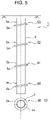
- a steel pipe pile 1 is an open-end steel pipe pile including a pile body 3 formed of a steel pipe having an outer diameter D of ⁇ 800 mm or less and a plurality steps of blades 50 to 53 fixed by welding to the pile body 3 so as to project from an outer periphery of the pile body 3.
- the blades 50 to 53 respectively have projecting lengths w 0 to w 3 .
- the steel pipe has an outer diameter of ⁇ 100 mm to ⁇ 800 mm, which is a general outer diameter of a friction pile.
- the lower limit of the outer diameter of the steel pipe is ⁇ 100 mm is that if the outer diameter is less than 100 mm, even when the blade diameter is as large as 2.5 times the outer diameter of the steel pipe, the projecting length of the blade 50 is 75 mm or less and it is difficult to attach the blade 50.
- Fig. 2 is a graph showing the cross-sectional area and the circumference of the pile with respect to the pile diameter.
- the horizontal axis represents the pile diameter (mm).
- the left vertical axis represents the cross-sectional area (mm 2 ) of the pile, and the right vertical axis represents the circumference (mm) of the pile.
- the wall thickness is 1.3% of the pile diameter and that the minimum wall thickness is 9 mm. More specifically, it is assumed that the wall thickness is 9 mm when the pile diameter is ⁇ 600 or less, and is 1.3% of the pile diameter when the pile diameter is ⁇ 700 or more.
- the blades 50 to 53 that project from the outer peripheral surface of the pile body 3 by the projecting lengths w 0 to w 3 are fixed with the intervals of h 1 to h 3 therebetween.
- the blades 50 to 53 illustrated in Fig. 1 are spiral blades, and are shaped such that one revolution of the blades 50 to 53 causes an upward displacement corresponding to one pitch (p 0 to p 3 ) thereof.
- the shapes of the blades 50 to 53 are not limited to this.
- the blades 50 to 53 may instead be arranged such that bottom end portions thereof are at different positions in the circumferential direction of the pile body 3.
- the positions of the bottom ends of the blades 50 to 53 are shifted from each other by 180°. This is preferred because the linearity of movement during installation can be increased.
- the pile is rotated so that a large propulsive force is generated at the lowermost blade 50. This force serves to insert the pile into the ground.
- the blades 51 to 53 other than the lowermost blade 50 are also inserted into the ground.
- the pitches of the blades 51 to 53 other than the lowermost blade 50 are equal to the pitch of the lowermost blade 50, the lowermost blade 50 and the other blades 51 to 53 can be inserted at the same rate per revolution. Accordingly, as the lowermost blade 50 is inserted, the blades 51 to 53 other than the lowermost blade 50 can also be smoothly inserted into the ground, and disturbance of the ground does not occur.
- the number of blades 50 to 53 is not particularly limited as long as a plurality steps of blades are provided.
- the four blades 50 to 53 are attached over the entire length of the pile.
- the structure may instead be such that no blades are arranged on a portion to be disposed in a weak layer in which the expected skin friction is very small, and that two blades 50 and 51 are provided only on a portion to be disposed in a lower layer in which the expected skin friction is large.
- the blades be provided over the entire length of the pile body 3.
- the projecting lengths of the blades and the intervals between the blades be equal to each other.
- each blade is not limited to a spiral blade formed of a single steel plate.
- each blade may instead be a pseudo spiral blade obtained by attaching two flat plates 5a such that the flat plates 5a are inclined in opposite directions.
- the use of the flat plates 5a is preferred because it is not necessary to perform press forming on steel plates and the costs can be reduced.
- the blade diameter Dw 0 of the lowermost blade 50 is 2.0 to 2.5 times the outer diameter D of the pile body 3, and the blade diameters Dw 1 to Dw 3 of the blades 51 to 53 other than the lowermost blade 50 are 2.0 times the outer diameter D of the pile body 3 or less.
- the projecting lengths w 0 to w 3 of the blades 50 to 53 are all set to the same length. However, in the present invention, it is not necessary that the projecting lengths of the blades 50 to 53 all be set to the same length.
- the projecting length w 0 of the lowermost blade 50 may be longer than the projecting lengths w 1 to w 3 of the other blades 51 to 53. This is preferred in that the propulsive force of the steel pipe pile 1 can be increased and the workability can be improved.
- the projecting lengths of the blades to be disposed in a weak layer in the ground may be set to lengths shorter than the projecting lengths of other blades.
- the thickness of the lowermost blade 50 is preferably set to a thickness greater than those of the other blades 51 to 53.
- the thickness of the lowermost blade 50 may be set based on the relationship between the thickness and the supporting force to be exerted by the lowermost blade 50, and the thicknesses of the other blades 51 to 53 may be set to thicknesses less than that of the lowermost blade 50.
- the lowermost blade 50 is preferably attached at a position that is 1 m or less from the end of the pile body 3 and that is as close to the end of the pile as possible within a range in which welding can be appropriately performed. More specifically, a distance x from the end of the pile body 3 to the lowermost blade 50 is preferably as small as possible within the range of x ⁇ 1 m to ensure good workability of the steel pipe pile 1 (see Fig. 1 ).
- the projecting lengths w 1 to w 3 of the blades 51 to 53 other than the lowermost blade 50 among the blades 50 to 53 and the intervals h 1 to h 3 from the blades 51 to 53 to the blades 50 to 52 that are downwardly adjacent to the blades 51 to 53 satisfy 10 ⁇ h k /w k ⁇ 30 (k is an integer of 1 or more).
- the supporting force of the steel pipe pile 1 having the multiple steps of blades 50 to 53 is the sum of the skin friction and the supporting pressures of the blades 50 to 53.
- the skin friction increases as the area increases, and therefore increases as the circumference along which the skin friction is exerted increases.
- the supporting pressures of the blades 50 to 53 increase as the areas of the projecting portions of the blades 50 to 53 increase.
- the supporting force (sum of the skin friction and the supporting pressures) obtained in a certain section of the steel pipe pile 1 will now be discussed.
- the surface area at which the skin friction is exerted is the surface area of the pile body 3.
- the supporting force of the pile depends on the relationship between the intervals h 1 to h 3 between the blades 50 to 53 and the projecting lengths w 1 to w 3 of the blades.
- the blades 50 to 53 are attached to the pile body 3 by welding.
- the fixture strength of the lowermost blade 50 is preferably set to a strength greater than the fixture strengths of the other blades 51 to 53.
- the lowermost blade 50 When a plurality steps of blades 50 to 53 are attached, the lowermost blade 50 generally exerts a greater supporting force than those exerted by the other blades 51 to 53, although this also depends on hardness of the ground. This is because although the blades 51 to 53 above the lowermost blade 50 mainly exert the supporting force based on the ground around the peripheral surface of the pile, the lowermost blade 50 exerts the supporting force based on not only the ground around the pile but also the ground below the bottom end of the pile.
- the lowermost blade 50 moves into the ground while drilling the ground, and then the other blades 51 to 53 are inserted into the ground that has already been drilled once. Therefore, the lowermost blade 50 also receives a large resistance during installation.
- the welding specifications and the blade thickness may be set in consideration of the supporting force and the bearing capacity during installation only for the lowermost blade 50, and the welding specifications for the other blades 51 to 53 may be set based on a smaller bearing capacity.
- the weight of the weld metal and the steel material can be reduced without affecting the workability and the supporting force, and the costs can be reduced.
- the welding specifications for the lowermost blade 50 may be changed from those for the other blades 51 to 53 by, for example, performing double side fillet welding on the lowermost blade 50 while performing single side fillet welding on the other blades 51 to 53.
- the welding method is basically fillet welding, and the fixture strength is generally controlled based on the leg length. Accordingly, the fixture strength of the lowermost blade 50 may be increased by setting the welding leg length for the lowermost blade 50 to a length longer than those for the other blades 51 to 53 by 20% or more.
- the lowermost blade 50 may be fixed by full penetration welding while the other blades 51 to 53 are fixed by double side fillet welding, single side fillet welding, or a combination of double side fillet welding and single side fillet welding.
- the fixture strength or the thickness of only the lowermost blade 50 is increased.
- the fixture strengths or the thicknesses of the other blades 51 to 53 are reduced.
- the costs of the blades can be reduced without affecting the supporting force and the workability.
- the projecting lengths w 1 to w 3 of the blades 51 to 53 other than the lowermost blade 50 are equal to each other. Therefore, the design of the supporting force and the manufacture of the steel pipe pile 1 can be simplified, and the costs can be reduced.
- Fig. 6 illustrates the test results.
- the horizontal axis represents the ratio (h k/ w k ) between the distance h between the blades and the projecting length w of the blades
- the vertical axis represents a coefficient of skin friction ⁇ (kN/m 2 ).
- the coefficient of skin friction of a steel pipe pile with no blades is assumed to be 2 (kN/m 2 ) irrespective of the diameter of the steel pipe.
- a value corresponding to the coefficient of skin friction was calculated for the piles having multiple steps of blades. More specifically, a load was applied to each reduced-scale model, and the supporting force was measured. Then, a value obtained by dividing the supporting force by the surface area of a cylinder having a diameter equal to the blade diameter and a length equal to the length of the pile was plotted in the graph as a coefficient of skin friction.
- the coefficients of skin friction for Comparative Examples 1 and 2 are less than 2 (kN/m 2 ).
- the coefficients of skin friction for Invention Examples 1 and 2, in which h k /w k is within the range of the present invention are greater than 2 (kN/m 2 ), and are significantly greater than those for Comparative Examples 1 and 2.
- a full-scale test was carried out to confirm that the data of the above-described model test corresponds to that of full-scale piles.
- the pile diameter was 318.5 mm
- the blade diameter was 1.5 times the pile diameter, that is, 477.75 mm
- the interval h between the blades was 1200 mm
- the projecting length w of the blades was 79.625 mm
- h k /w k was 15.1.
- the result of the full-scale test is plotted with a white circle in Fig. 6 .
- the coefficient of skin friction is 4.762 kN/m 2 , which substantially matches the data of the model test. This demonstrates that the data of the above-described model test corresponds to that of full-scale piles.
- Example 1 the test was a soil-layer test for determining a supporting force by using a reduced-scale model having the same ratios as those of a real pile.
- the N-value of the soil layer was 20.
- a test pile used as the reduced-scale model included a steel pipe having a diameter of 76.3 mm and a wall thickness of 2.8 mm. The number of blades was 3, and h/w was 12.6.
- Fig. 7 shows the test results.
- the vertical axis of the graph of Fig. 7 represents the load-bearing ratio obtained assuming that the load borne by all of the blades 50 to 53 in response to a downward vertical displacement applied to the pile head is 1.
- the horizontal axis represents the displacement of the pile head normalized by the blade diameter.
- the graph shows the load-bearing ratio of the lowermost blade 50 and the total load-bearing ratio of two upper blades.
- the load applied when the displacement is 10% of the blade diameter, which is the pile diameter, is generally defined as the limit load. Accordingly, referring to the load-bearing ratios of the blades 5 at the pile head displacement corresponding to the limit load (0.1), the load-bearing ratio is 0.65 for the lowermost blade 5 and 0.35 for the two upper blades.
- the load-bearing ratio of the lowermost blade 50 is large. This demonstrates that it is reasonable to increase the fixture strength or the thickness of only the lowermost blade 50 as described above.
Landscapes
- Engineering & Computer Science (AREA)
- Structural Engineering (AREA)
- Life Sciences & Earth Sciences (AREA)
- General Life Sciences & Earth Sciences (AREA)
- Mining & Mineral Resources (AREA)
- Paleontology (AREA)
- Civil Engineering (AREA)
- General Engineering & Computer Science (AREA)
- Piles And Underground Anchors (AREA)
Applications Claiming Priority (2)
| Application Number | Priority Date | Filing Date | Title |
|---|---|---|---|
| JP2020019449 | 2020-02-07 | ||
| PCT/JP2021/004344 WO2021157699A1 (fr) | 2020-02-07 | 2021-02-05 | Pieu tubulaire en acier |
Publications (2)
| Publication Number | Publication Date |
|---|---|
| EP4101986A1 true EP4101986A1 (fr) | 2022-12-14 |
| EP4101986A4 EP4101986A4 (fr) | 2023-07-26 |
Family
ID=77199994
Family Applications (1)
| Application Number | Title | Priority Date | Filing Date |
|---|---|---|---|
| EP21750285.5A Pending EP4101986A4 (fr) | 2020-02-07 | 2021-02-05 | Pieu tubulaire en acier |
Country Status (4)
| Country | Link |
|---|---|
| EP (1) | EP4101986A4 (fr) |
| JP (1) | JP7272444B2 (fr) |
| PH (1) | PH12022552007A1 (fr) |
| WO (1) | WO2021157699A1 (fr) |
Family Cites Families (14)
| Publication number | Priority date | Publication date | Assignee | Title |
|---|---|---|---|---|
| JP2592079B2 (ja) | 1987-11-27 | 1997-03-19 | 旭化成工業株式会社 | 小口径鋼管杭 |
| JP2590157Y2 (ja) * | 1992-09-30 | 1999-02-10 | 千代田工営株式会社 | 多翼円錐状鋼管杭 |
| JPH08199568A (ja) * | 1995-01-23 | 1996-08-06 | Tamotsu Nakamura | 基礎杭打設工法と基礎杭 |
| JP2861937B2 (ja) | 1996-06-06 | 1999-02-24 | 日本鋼管株式会社 | ねじ込み式鋼管杭 |
| JPH1037182A (ja) * | 1996-07-23 | 1998-02-10 | Nkk Corp | ねじ込み式鋼管杭 |
| JP3510988B2 (ja) * | 1999-06-09 | 2004-03-29 | 株式会社国土基礎 | 鋼管杭 |
| JP4496553B2 (ja) * | 2003-02-17 | 2010-07-07 | 三谷セキサン株式会社 | 基礎杭の造成方法及び既製杭 |
| JP5200941B2 (ja) | 2008-02-08 | 2013-06-05 | Jfeスチール株式会社 | ねじ込み式杭 |
| US9115478B2 (en) * | 2011-10-25 | 2015-08-25 | Hubbell Incorporated | Helical screw pile |
| US8506207B2 (en) * | 2011-10-25 | 2013-08-13 | Hubbell Incorporated | Helical screw pile |
| ITRE20120016A1 (it) * | 2012-03-09 | 2013-09-10 | Kappazeta Spa | Metodo e dispositivo di consolidamento del terreno |
| JP6237078B2 (ja) * | 2012-11-21 | 2017-11-29 | 新日鐵住金株式会社 | 杭の継手構造及び杭の立設方法 |
| CA2941743C (fr) * | 2014-03-19 | 2018-09-18 | Asahi Kasei Construction Materials Corporation | Empilement de tuyaux en acier a lames en spirale, empilement composite et methode de construction d'un empilement composite |
| JP6749718B1 (ja) * | 2020-01-31 | 2020-09-02 | 株式会社三誠 | 鋼管杭の埋設方法 |
-
2021
- 2021-02-05 EP EP21750285.5A patent/EP4101986A4/fr active Pending
- 2021-02-05 PH PH1/2022/552007A patent/PH12022552007A1/en unknown
- 2021-02-05 WO PCT/JP2021/004344 patent/WO2021157699A1/fr not_active Ceased
- 2021-02-05 JP JP2021541425A patent/JP7272444B2/ja active Active
Also Published As
| Publication number | Publication date |
|---|---|
| JP7272444B2 (ja) | 2023-05-12 |
| EP4101986A4 (fr) | 2023-07-26 |
| JPWO2021157699A1 (fr) | 2021-08-12 |
| WO2021157699A1 (fr) | 2021-08-12 |
| PH12022552007A1 (en) | 2023-11-29 |
Similar Documents
| Publication | Publication Date | Title |
|---|---|---|
| JP4559774B2 (ja) | フレア付き鋼管、鋼管継手、鋼管杭、鋼管柱とフレア付き鋼管の製造方法 | |
| EP2615226B1 (fr) | Structure de colonne de tuyau d'acier et procédé pour sa production | |
| US9598831B2 (en) | Helical screw pile | |
| US8821075B2 (en) | Yieldable support prop and method | |
| CA2853456C (fr) | Pieu a vis helicoidales | |
| US20130309023A1 (en) | Depression-provided steel pipe and composite pile | |
| JP5365462B2 (ja) | 基礎杭構造の構築方法 | |
| CN109477383A (zh) | 一种抗腐蚀可缩锚杆 | |
| JP2016003431A (ja) | スパイラル杭基礎 | |
| EP4101986A1 (fr) | Pieu tubulaire en acier | |
| AU2023274184B2 (en) | Column shoe manufactured from one piece of sheet metal | |
| JP2005016212A (ja) | 露出型鉄骨柱脚 | |
| JP2005299192A (ja) | 回転圧入鋼管杭およびその施工法 | |
| CN106592806B (zh) | 一种高阻尼金属剪切滞变消能器 | |
| TWI384107B (zh) | 鋼管樁 | |
| JP4708295B2 (ja) | 杭と柱の接合構造 | |
| JP2024092802A (ja) | 鋼管杭及び鋼管杭の施工方法 | |
| CN224173300U (zh) | 一种防咬合支护桩钢筋笼 | |
| CN219343292U (zh) | 塔桩基础 | |
| JP7513575B2 (ja) | 回転貫入鋼管杭、該回転貫入鋼管杭の施工方法 | |
| JP2004190268A (ja) | ねじり座屈に対して補強された回転圧入鋼管杭 | |
| KR20250057156A (ko) | 말뚝, 말뚝의 시공 방법, 구조물, 구조물의 구축 방법, 말뚝의 설계 방법 및 말뚝의 제조 방법 | |
| WO2025217667A1 (fr) | Accesoire de rendement | |
| CN202031086U (zh) | 一种预应力基础空心混凝土方桩 | |
| JPS6215586Y2 (fr) |
Legal Events
| Date | Code | Title | Description |
|---|---|---|---|
| STAA | Information on the status of an ep patent application or granted ep patent |
Free format text: STATUS: THE INTERNATIONAL PUBLICATION HAS BEEN MADE |
|
| PUAI | Public reference made under article 153(3) epc to a published international application that has entered the european phase |
Free format text: ORIGINAL CODE: 0009012 |
|
| STAA | Information on the status of an ep patent application or granted ep patent |
Free format text: STATUS: REQUEST FOR EXAMINATION WAS MADE |
|
| 17P | Request for examination filed |
Effective date: 20220803 |
|
| AK | Designated contracting states |
Kind code of ref document: A1 Designated state(s): AL AT BE BG CH CY CZ DE DK EE ES FI FR GB GR HR HU IE IS IT LI LT LU LV MC MK MT NL NO PL PT RO RS SE SI SK SM TR |
|
| DAV | Request for validation of the european patent (deleted) | ||
| DAX | Request for extension of the european patent (deleted) | ||
| A4 | Supplementary search report drawn up and despatched |
Effective date: 20230623 |
|
| RIC1 | Information provided on ipc code assigned before grant |
Ipc: E02D 5/56 20060101ALI20230619BHEP Ipc: E02D 5/28 20060101AFI20230619BHEP |
|
| STAA | Information on the status of an ep patent application or granted ep patent |
Free format text: STATUS: EXAMINATION IS IN PROGRESS |
|
| 17Q | First examination report despatched |
Effective date: 20250328 |