EP4102006A1 - Poutre pour système d'échafaudage - Google Patents
Poutre pour système d'échafaudage Download PDFInfo
- Publication number
- EP4102006A1 EP4102006A1 EP21179104.1A EP21179104A EP4102006A1 EP 4102006 A1 EP4102006 A1 EP 4102006A1 EP 21179104 A EP21179104 A EP 21179104A EP 4102006 A1 EP4102006 A1 EP 4102006A1
- Authority
- EP
- European Patent Office
- Prior art keywords
- openings
- male
- female
- proximal
- distal
- Prior art date
- Legal status (The legal status is an assumption and is not a legal conclusion. Google has not performed a legal analysis and makes no representation as to the accuracy of the status listed.)
- Withdrawn
Links
Images

Classifications
-
- E—FIXED CONSTRUCTIONS
- E04—BUILDING
- E04G—SCAFFOLDING; FORMS; SHUTTERING; BUILDING IMPLEMENTS OR AIDS, OR THEIR USE; HANDLING BUILDING MATERIALS ON THE SITE; REPAIRING, BREAKING-UP OR OTHER WORK ON EXISTING BUILDINGS
- E04G1/00—Scaffolds primarily resting on the ground
- E04G1/02—Scaffolds primarily resting on the ground composed essentially of members elongated in one dimension [1D] only, e.g. poles, lattice masts, with or without end portions of special form, connected together by any means
- E04G1/12—Scaffolds primarily resting on the ground composed essentially of members elongated in one dimension [1D] only, e.g. poles, lattice masts, with or without end portions of special form, connected together by any means comprising members of special, e.g. composite, cross-section or with lugs or the like or lateral apertures for supporting or attaching other members
-
- E—FIXED CONSTRUCTIONS
- E04—BUILDING
- E04G—SCAFFOLDING; FORMS; SHUTTERING; BUILDING IMPLEMENTS OR AIDS, OR THEIR USE; HANDLING BUILDING MATERIALS ON THE SITE; REPAIRING, BREAKING-UP OR OTHER WORK ON EXISTING BUILDINGS
- E04G1/00—Scaffolds primarily resting on the ground
- E04G1/15—Scaffolds primarily resting on the ground essentially comprising special means for supporting or forming platforms; Platforms
-
- E—FIXED CONSTRUCTIONS
- E04—BUILDING
- E04G—SCAFFOLDING; FORMS; SHUTTERING; BUILDING IMPLEMENTS OR AIDS, OR THEIR USE; HANDLING BUILDING MATERIALS ON THE SITE; REPAIRING, BREAKING-UP OR OTHER WORK ON EXISTING BUILDINGS
- E04G5/00—Component parts or accessories for scaffolds
- E04G5/16—Struts or stiffening rods, e.g. diagonal rods
- E04G5/165—Lintel for scaffoldings
-
- E—FIXED CONSTRUCTIONS
- E04—BUILDING
- E04G—SCAFFOLDING; FORMS; SHUTTERING; BUILDING IMPLEMENTS OR AIDS, OR THEIR USE; HANDLING BUILDING MATERIALS ON THE SITE; REPAIRING, BREAKING-UP OR OTHER WORK ON EXISTING BUILDINGS
- E04G7/00—Connections between parts of the scaffold
- E04G7/30—Scaffolding bars or members with non-detachably fixed coupling elements
- E04G7/301—Scaffolding bars or members with non-detachably fixed coupling elements for connecting bars or members which are parallel or in end-to-end relation
-
- E—FIXED CONSTRUCTIONS
- E04—BUILDING
- E04G—SCAFFOLDING; FORMS; SHUTTERING; BUILDING IMPLEMENTS OR AIDS, OR THEIR USE; HANDLING BUILDING MATERIALS ON THE SITE; REPAIRING, BREAKING-UP OR OTHER WORK ON EXISTING BUILDINGS
- E04G7/00—Connections between parts of the scaffold
- E04G7/30—Scaffolding bars or members with non-detachably fixed coupling elements
- E04G7/302—Scaffolding bars or members with non-detachably fixed coupling elements for connecting crossing or intersecting bars or members
- E04G7/306—Scaffolding bars or members with non-detachably fixed coupling elements for connecting crossing or intersecting bars or members the added coupling elements are fixed at several bars or members to connect
- E04G7/307—Scaffolding bars or members with non-detachably fixed coupling elements for connecting crossing or intersecting bars or members the added coupling elements are fixed at several bars or members to connect with tying means for connecting the bars or members
Definitions
- the invention relates to a beam for a scaffolding system.
- the invention further relates to a beam assembly and to a scaffolding system, comprising said beam.
- a scaffolding system generally comprises a plurality of beams that can be joined together so as to form a frame.
- the beams may support deck panels such that a platform may be assembled.
- a scaffolding system may be used for assembling a platform that can be located below a bridge deck or similar whereby maintenance work, or other types of operations, may be performed.
- An object of the invention is to provide a beam for a scaffolding system, which beam can be assembled in an scaffolding system in an appropriate manner.
- the object is achieved by a beam for a scaffolding system, the beam having a longitudinal extension along a longitudinal direction, the beam further having a vertical extension along a vertical direction being perpendicular to the longitudinal direction, the beam further having a transversal extension along a transversal direction being perpendicular to the longitudinal direction as well as to the vertical direction, the extension of the beam in the transversal direction being smaller than the extension of the beam in the vertical direction, the extension of the beam in the vertical direction being smaller than the extension in the longitudinal direction.
- the beam further comprises a centre line extending in the vertical direction and being located in the longitudinal centre of the beam.
- a first longitudinal end of the beam comprises a male connection member and a second longitudinal end of the beam comprises a female connection member.
- the male connection member comprises a proximal male set of openings and a distal male set of openings, each one of the proximal male and the distal male second set of openings comprising a plurality of openings, the proximal male set of openings being located closer to the centre line than the distal male set of openings.
- the female connection member comprises a proximal female set of openings and a distal female set of openings, each one of the proximal female and the distal female second set of openings comprising a plurality of openings, the proximal female set of openings being located closer to the centre line than the distal female set of openings.
- the beam is such that it can be connected to a second beam of the same type such that the proximal male set of openings of the beam is aligned with the distal female set of openings of the second beam such that a first alignment line, extending in the vertical direction, extends through each opening of the proximal male set of openings as well as the distal female set of openings of the second beam, and such that the distal male set of openings of the beam is aligned with the proximal female set of openings of the second beam such that a second alignment line, extending in the vertical direction, extends through each opening the distal male set of openings of the beam as well as the proximal female set of openings of the second beam.
- the beam according to the present invention implies that two beams of the same type can be connected together in an appropriate manner.
- the beam in accordance with the present invention implies that two beams of the same type may be connected together without the need of interconnecting members located longitudinally between the beams. Instead, the two beams may be connected together by means of joint pins or the like.
- each opening of the proximal male and the distal male second set of openings has a horizontal opening centre point in the longitudinal direction and the transversal direction, respectively, wherein the horizontal opening centre point of each opening of the proximal male set of openings is the same and equals a proximal male horizontal opening centre point and wherein the horizontal opening centre point of each opening of the distal male set of openings is the same and equals a distal male horizontal opening centre point.
- a distance between the proximal male horizontal opening centre point and the distal male horizontal opening centre point in the longitudinal direction is at least 5 mm, preferably at least 10 mm.
- a distance at or above any one of the above limits implies a reliable locking of beams of the same type to each other.
- each opening of the proximal female and the distal female second set of openings has a horizontal opening centre point in the longitudinal direction and the transversal direction, respectively, wherein the horizontal opening centre point of each opening of the proximal female set of openings is the same and equals a proximal female horizontal opening centre point and wherein the horizontal opening centre point of each opening of the distal female set of openings is the same and equals a distal female horizontal opening centre point.
- a distance between the proximal female horizontal opening centre point and the distal female horizontal opening centre point in the longitudinal direction is at least 5 mm, preferably at least 10 mm.
- a distance between the proximal female horizontal opening centre point and the distal female horizontal opening centre point in the longitudinal direction is equal to a distance between the proximal male horizontal opening centre point and the distal male horizontal opening centre point in the longitudinal direction.
- each one of the proximal female horizontal opening centre point, the distal female horizontal opening centre point, the proximal male horizontal opening centre point and the distal male horizontal opening centre point has the same location in the transversal direction.
- the beam may be relatively narrow whilst nevertheless ensuring that two beams may be connected together in an appropriate manner.
- the beam is such that it can be connected to the second beam of the same type such that a first joint pin can be inserted into the proximal male set of openings of the beam and the distal female set of openings of the second beam, whereby the beam and the second beam can be pivoted relative to each other around a pivot axle extending in the vertical direction.
- the above possibility to pivot a second beam relative to the beam implies an appropriate flexibility when connecting the beams to each other.
- the second beam may firstly be connected to the beam using the first joint pin and the second beam may thereafter be swung into a target position by pivoting the second beam relative to the beam.
- the beam is such that it can be connected to the second beam of the same type such that the first joint pin can be inserted into the proximal male set of openings of the beam and the distal female set of openings of the second beam and a second joint pin can be inserted into the distal male set of openings of the beam and the proximal female set of openings of the second beam, whereby the beam and the second beam are prevented from being pivoted relative to each other around a pivot axle extending in the vertical direction.
- the male connection member comprises a set of male connection member tongues, each one of the male connection member tongues extending in the longitudinal direction, each one of the male connection member tongue being located at a distance, in the vertical direction, from each one of the other male connection member tongues, the set of male connection member tongues accommodating the proximal male set of openings and the distal male set of openings.
- the female connection member comprises a plurality of female connection member tongues, each one of the female connection member tongues extending in the longitudinal direction, each one of the female connection member tongue being located at a distance, in the vertical direction, from each one of the other female connection member tongues, the set of female connection member tongues accommodating the proximal female set of openings and the distal female set of openings, the beam being such that it can be connected to a second beam of the same type such that the male connection member tongues of the beam is engaged with the female connection member tongues of the second beam, whereby, as seen in the vertical direction, each male connection member tongue is located closer to a female connection member tongue than to another male connection member tongue.
- the beam comprises a plurality of transversely extending openings in a portion of the beam located between the male connection member and the female connection member.
- the object is achieved by a beam assembly comprising a first beam according to any one of the preceding claims and a second beam according to any one of the preceding claims, the beam assembly further comprising a first joint pin adapted to be inserted into the proximal male set of openings of the first beam and the distal female set of openings of the second beam such that the beam and the second beam may be pivoted relative to each other around a pivot axle extending in the vertical direction.
- the beam assembly further comprises a second joint pin adapted to be inserted into the distal male set of openings of the first beam and the proximal female set of openings of the second beam, whereby the beam and the second beam may be prevented from being pivoted relative to each other when the first joint pin is inserted into the proximal male set of openings of the first beam and the distal female set of openings of the second beam and the second joint pin is inserted into the distal male set of openings of the first beam and the proximal female set of openings of the second beam.
- each one of the first and second beams comprises a longitudinally extending groove for receiving a deck panel connection member, the first and second beams and the first joint pin being such that when the first joint pin is inserted into the proximal male set of openings of the first beam and the distal female set of openings of the second beam and when the second joint pin is inserted into the distal male set of openings of the first beam and the proximal female set of openings of the second beam, the longitudinally extending groove extends uninterruptedly from the first beam to the second beam.
- a scaffolding system comprising a beam assembly according to the second aspect, and a deck panel, the deck panel comprising a deck panel connection member adapted to be connected to at least one of the first and second beams.
- Figs 1a -1b illustrate an example of a beam according to the present disclosure.
- the beam 1 has a longitudinal extension along a longitudinal direction L, a vertical extension along a vertical direction V being perpendicular to the longitudinal direction L, and a transversal extension along a transversal direction T being perpendicular to the longitudinal direction L as well as to the vertical direction V.
- the extension of the beam 1 in the transversal direction T is smaller than the extension of the beam 1 in the vertical direction V, and the extension of the beam 1 in the vertical direction V is smaller than the extension in the longitudinal direction L.
- the beam 1 when used in a scaffolding system it is envisaged that the beam 1 is intended for use primarily with its longitudinal direction L generally aligned with a horizontal direction in space, and its vertical direction V generally aligned with a vertical direction in space.
- the beam 1 further comprises a centre line C extending in the vertical direction and being located in the longitudinal centre of the beam 1.
- the centre line C may also be located in the transversal centre of the beam 1.
- the beam 1 may be manufactured in any material suitable for a scaffolding system, such as metal, for instance aluminium and/or an aluminium alloy.
- the beam 1 may be configured to allow attachment of various devices to the beam 1.
- the beam 1 may be configured to allow attachment of the beam e.g. to vertical scaffolding beams (not shown) and/or to allow attachment of a deck panel (not shown) to the beam, e.g. via a deck panel attachment member.
- the beam 1 may comprise a longitudinally extending groove 42 for receiving a connection member to a device in a scaffolding system, such as for receiving a deck panel connection member.
- the groove 42 may, as in the illustrated example of Figs 1a-1b , extend continuously over the longitudinal extension of the beam 1.
- the groove 42 may, as in the illustrated example, extend adjacent a vertical end of the beam 1, such as adjacent the upper vertical end 1.
- the beam 1 as described herein may further comprise a plurality of transversely extending openings 40 in a portion of the beam 1 located between the male connection member 12 and the female connection member 22.
- the number and shape of the transversely extending openings 40 may be varied.
- the transversely extending openings 40 may be used for connecting a fastening device such a suspension shoe (not shown) to the beam.
- a suspension cable such as a wire or chain, maybe connected to the fastening device such that the beam 1 may be suspended from an object, such as a bridge deck, via the suspension cable.
- a plurality of fastening devices and/or suspension cables may be connected to a beam in order to enable suspension thereof.
- a first longitudinal end 10 of the beam 1 comprises a male connection member 12 and a second longitudinal end 20 of the beam 1 comprises a female connection member 22.
- the male connection member 12 comprises a proximal male set of openings 14 and a distal male set of openings 16, each one of the proximal male and the distal male set of openings 14, 16 comprising a plurality of openings.
- proximal and distal are used herein with reference to the central line C and the longitudinal direction L.
- proximal male set of openings 14 is located closer to the centre line C than the distal male set of openings 16 in the longitudinal direction L.
- the female connection member 22 comprises a proximal female set of openings 24 and a distal female set of openings 26.
- Each one of the proximal female and the distal female second set of openings 24, 26 comprises a plurality of openings, and the proximal female set of openings 24 is located closer to the centre line C than the distal female set of openings 26.
- the male connection member 12 and the female connection member 22 may be configured to have complementary shapes, such that the male connection member 12 of a first beam 1 and the female connection member of a second beam 1' of the same type as the first beam 1 may assume a connection position (see Fig. 2b ) when brought together.
- a connection position one or more connection elements of the male connection member 12 and one or more connection elements of the female connection member 22 overlap as seen along the vertical direction V.
- the proximal and distal male set of openings 14, 16 and the proximal and distal female set of openings 24, 26 may be comprised in the overlapping one or more connection elements of the male connection member 12 and the female connection member 22, respectively.
- the proximal male set of openings 14 of the beam 1 may be aligned with the distal female set of openings 26' of the second beam 1' such that a first alignment line a1, extending in the vertical direction, extends through each opening of the proximal male set of openings 14 as well as the distal female set of openings 26' of the second beam 1'.
- the distal male set of openings 16 of the beam 1 is aligned with the proximal female set of openings 24' of the second beam 1' such that a second alignment line a2, extending in the vertical direction, extends through each opening the distal male set of openings 16 of the beam 1 as well as the proximal female set of openings 24' of the second beam 1'.
- first and second alignment lines a1, a2 will extend along the vertical direction V through one or more of the connection elements of the male connection member 12 of the first beam 1 and one or more of the connection elements of the female connection member 22 of the second beam 1'.
- male connection members 12 and female connection members 22 may have different complementary shapes and/or connection elements to accomplish the alignments of the sets of openings 14, 26', 16, 26' of the first and second beam 1, 1' respectively, as explained in the above.
- the male connection member 12 may comprise a set of male connection member tongues 18, each one of the male connection member tongues 18 extending in the longitudinal direction L.
- Each one of the male connection member tongues 18 is located at a distance, in the vertical direction V, from each one of the other male connection member tongues 18.
- the female connection member 22 may comprise a plurality of female connection member tongues 28.
- Each one of the female connection member tongues 28 extends in the longitudinal direction L, and each one of the female connection member tongues 28 being located at a distance, in the vertical direction V, from each one of the other female connection member tongues 28.
- the set of male connection member tongues 18 accommodates the proximal male set of openings 14 and the distal male set of openings 16.
- the set of female connection member tongues 28 accommodates the proximal female set of openings 24 and the distal female set of openings 26.
- each male connection member tongue 18 is located closer to a female connection member tongue 28' than to another male connection member tongue 18.
- proximal male set of openings 14 of the beam 1 are aligned with the distal female set of openings 26' of the second beam 1' such that a first alignment line a1, extending in the vertical direction, extends through each opening of the proximal male set of openings 14 as well as the distal female set of openings 26' of the second beam 1'.
- the distal male set of openings 16 of the beam 1 is aligned with the proximal female set of openings 24' of the second beam 1' such that a second alignment line a2, extending in the vertical direction, extends through each opening the distal male set of openings 16 of the beam 1 as well as the proximal female set of openings 24' of the second beam 1'.
- connection elements i.e. the male and female connection member tongues 28 need not necessarily all be of a similar configuration.
- the female connection member 20 comprises three connection member tongues 28.
- a set of the female connection member tongues 28, in the illustrated variant being two female connection member tongues 28, accommodates openings of the proximal female set of openings 24 and the distal female set of openings 26.
- a second set of the female connection member tongues 28, in the illustrated variant being one female connection member tongue 28, accommodates only openings of the proximal female set of openings 24.
- the second set of female connection member tongues 28 has an extension along the longitudinal direction L being shorter than that of the first set of female connection member tongues 28.
- the opening of the proximal male and the distal male second set of openings 14, 16 has a horizontal opening centre point in the longitudinal direction L and the transversal direction T, respectively.
- the horizontal opening centre point of each opening of the proximal male set of openings 14 may be the same and may equal a proximal male horizontal opening centre point P14.
- the horizontal opening centre point of each opening of the distal male set of openings 16 may be the same and may equal a distal male horizontal opening centre point P16.
- the distance between the proximal male horizontal opening centre point P14 and the distal male horizontal opening centre point P16 in the longitudinal direction L may be selected depending e.g. on the dimensions of the beam 1.
- the distance between the proximal male horizontal opening centre point P14 and the distal male horizontal opening centre point P16 in the longitudinal direction L may be at least 5 mm, preferably at least 10 mm.
- each opening of the proximal female and the distal female second set of openings 24, 26 has a horizontal opening centre point in the longitudinal direction L and the transversal direction T, respectively, wherein the horizontal opening centre point of each opening of the proximal female set of openings 24 may be the same and may equal a proximal female horizontal opening centre point P24 and wherein the horizontal opening centre point of each opening of the distal female set of openings 26 may be the same and may equal a distal female horizontal opening centre point P26.
- the distance between the proximal female horizontal opening centre point P24 and the distal male horizontal opening centre point P26 in the longitudinal direction L may be selected depending e.g. on the dimensions of the beam 1.
- the distance between the proximal female horizontal opening centre point P24 and the distal female horizontal opening centre point P26 in the longitudinal direction L is at least 5 mm, preferably at least 10 mm.
- the distance between the proximal male horizontal opening centre point P14 and the distal male horizontal opening centre point P16 in the longitudinal direction L is preferably the same as the distance between the proximal female horizontal opening centre point P24 and the distal female horizontal opening centre point P26 in the longitudinal direction L so as to enable the alignment of the male and female sets of openings along the first and second vertical lines a1, a2 as set out in the above.
- the proximal male horizontal opening centre point P14 and the distal female opening centre point P26 may be at a same transversal level as seen along the transversal direction T.
- the distal male horizontal opening centre point P16 and the proximal female opening centre point P24 may be at a same transversal level as seen along the transversal direction T.
- proximal male horizontal opening centre point P14, the distal female opening centre point P26, the distal male horizontal opening centre point P16 and the proximal female opening centre point P24 may all be at the same transversal level as seen along the transversal direction T.
- Said same transversal level may, as a non-limiting example, be in a plane comprising the centre axis C.
- the beam as described in the above, and as exemplified in the figures, may hence be such that it can be connected to the second beam 1' of the same type such that a first joint pin 31 can be inserted into the proximal male set of openings 14 of the beam 1 and the distal female set of openings 26' of the second beam 1'.
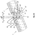
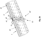
- Figs 2a-2b illustrate the male connection member 12 of a first beam 1 and a female connection member 22' of a second beam 1' of the same type as the first beam 1, in a state before connection Fig. 2a and when interconnected Fig. 2b .
- the beams 1, 1' are brought to a connection position where the proximal male set of openings 14 of the beam 1 is aligned with the distal female set of openings 26' of the second beam 1' such that a first alignment line a1, extending in the vertical direction, extends through each opening of the proximal male set of openings 14 as well as the distal female set of openings 26' of the second beam 1'.
- the distal male set of openings 16 of the beam 1 is aligned with the proximal female set of openings 24' of the second beam 1' such that a second alignment line a2, extending in the vertical direction, extends through each opening the distal male set of openings 16 of the beam 1 as well as the proximal female set of openings 24' of the second beam 1'.
- the relative positions of the beams 1, 1' illustrated in Fig. 2a is an example that is presented in order to elucidate the characteristics of the beam of the invention.
- two beams in accordance with the present invention must not necessarily be connected by moving the beams 1, 1' towards each other in the longitudinal direction L.
- the beams 1, 1' may be connected by a relative movement in another direction or directions, as will be presented hereinbelow.
- Figs 2a-2b illustrate an example of a first joint pin 31 which can be inserted into the proximal male set of openings 14 of the beam 1 and the distal female set of openings 26' of the second beam 1'.
- the first joint pin 31 may be inserted to extend along the first alignment line a1.
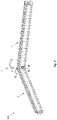
- Fig. 3 illustrates the exemplified first beam 1 and second beam 1' when the first joint pin 31 is inserted.
- the beam 1 and the second beam 1' are pivotable relative to each other around a pivot axle extending in the vertical direction V.
- the second beam 1' may be pivotable ⁇ 90° from a position in which the first beam 1 and the second beam 1' are parallel.
- insertion of a first joint pin 31 thus allows for a preliminary connection between a first beam 1 and a second beam 1', which allows the beam 1 and the second beam 1' to be pivotable relative to each other.
- the male connection member 12 of the first beam 1 and the female connection member 22' of the second beam 1' are approached such that the first joint pin 31 is insertable along the alignment line a1, i.e. that the proximal male set of openings 14 of the beam 1 is aligned with the distal female set of openings 26' of the second beam 1'.
- the distal male set of openings 16 of the beam 1 is also aligned with the proximal set of openings 24' of the second beam 1'.
- the first joint pin 31 it is for example not necessary that the first beam 1 and the second beam 1' are aligned along their longitudinal directions L. Instead, the first beam 1 and the second beam 1' may form an angle between their longitudinal extensions L.
- the beam 1 may further be such that it can be connected to the second beam 1' of the same type such that the first joint pin 31 can be inserted into the proximal male set of openings 14 of the beam 1 and the distal female set of openings 26' of the second beam 1' and a second joint pin 32 can be inserted into the distal male set of openings 16 of the beam 1 and the proximal female set of openings 24' of the second beam 1'.
- the second joint pin 32 may be inserted to extend along the second alignment line a2.
- the beam 1 and the second beam 1' With both the first joint pin 31 and the second joint pin 32 inserted, the beam 1 and the second beam 1' will be prevented from being pivoted relative to each other around a pivot axle extending in the vertical direction V. Thus, the first and second beams 1, 1' are securely interconnected.
- the beam 1 and the second beam 1' may be aligned along their longitudinal directions L.
- the beams 1, 1' as proposed herein may be joined to form a beam assembly 100 for example by firstly introducing the first joint pin 31 into the proximal male set of openings 14 of the first beam 1, and the distal female set of openings 26' of the second beam 1'.
- the introduction of the first joint pin 31 may be made while the longitudinal extensions L of the two beams 1, 1' forms an angle between each other. This may facilitate assembly of a first beam 1 and a second beam 1', since for example where there is restricted space, it may be possible to approach the two beams 1, 1' to each other towards a connectable position only with some angle between the beams 1, 1'.
- the first joint pin 31 When the first joint pin 31 is introduced, the first beam 1 and the second beam 1' are pivotable about an axis along said first joint pin 31. Hence, the beams 1, 1' may be pivotable to a relative aligned position, in which the longitudinal extensions L of the two beams 1, 1' are aligned. When the beams 1, 1' are in such an aligned position, the second joint pin 32 may be introduced, securing the beams 1, 1' in a fixed relative position.
- the first and/or second joint pin 31, 32 may be insertable along the vertical direction and from a vertical upper direction, as in the illustrated example.
- a first and a second beam 1, 1', with a first joint pin 31 and/or a second joint pin 32 may be referred to as a beam assembly 100, as exemplified e.g. in Figs. 2a-2b and Fig. 3 .
- One or more beam assemblies 100 may be used to form a scaffolding system.
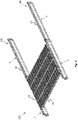
- Fig. 4 exemplifies a variant of a scaffolding system 200 comprising beam assemblies 100 as described herein.
- each beam assembly 100 comprising a first beam 1 and a second, similar beam 1'.
- each one of the first and second beams 1, 1' may comprise a longitudinally extending groove 42 for receiving a deck panel connection member 52, the first and second beams 1, 1' and the first joint pin 31 being such that when the first joint pin 31 is inserted into the proximal male set of openings 14 of the first beam 1 and the distal female set of openings 26' of the second beam 1' and when the second joint pin 32 is inserted into the distal male set of openings 16 of the first beam 1 and the proximal female set of openings 24' of the second beam 1', the longitudinally extending groove 42 extends uninterruptedly from the first beam 1 to the second beam 1'.
- This capability is also indicated in Fig.
- the above capability may be facilitated by the fact that the first joint pin 31 and the second joint pin 32 are arranged relative to the beams 1, 1' such that the portions of the pins 31, 32 protruding from the beams 1, 1' when the pins 31, 32 are inserted into the corresponding openings are not located in the extension in the groove 42.
- the heads of the pins 31, 32 - i.e. the portions of the pins intended to protrude from the beams 1, 1' are relatively flat.
- the scaffolding system further comprises a deck panel 50, the deck panel 50 comprising a deck panel connection member 52 adapted to be connected to at least one of the first and second beams 1, 1'.
- connection accomplished by the male connection member and the female connection member of the beam 1 enables the groove 42 to extend uninterrupted over the connection between a first beam 1 and a second beam 1'.
- the groove 42 may extend over a connection tongue 18 of the male connection member 12 at the first longitudinal end 10 of the beam 1.
- the groove 42 extends towards the female connection member 22.
- the groove 42 thus extends continuously over the beam 1, such that, when a first beam 1 and a second beam 1' are interconnected, their respective grooves 42, 42' may extend uninterrupted over the connection of the beams 1, 1'.
- the uninterrupted groove 42, 42' enables uninterrupted attachment of further scaffolding devices to the beam assembly 100, for example, a deck panel 50 may extend uninterrupted over the connection of two beams 1, 1'.
- the relative dimensions of the beam may be adapted to various needs.
- the shape of the male connection member and the female connection member may be varied.
- the number and/or shape of the connection elements, such as connection member tongues, may be varied.
Landscapes
- Engineering & Computer Science (AREA)
- Architecture (AREA)
- Mechanical Engineering (AREA)
- Civil Engineering (AREA)
- Structural Engineering (AREA)
- Chemical & Material Sciences (AREA)
- Composite Materials (AREA)
- Mutual Connection Of Rods And Tubes (AREA)
Priority Applications (2)
| Application Number | Priority Date | Filing Date | Title |
|---|---|---|---|
| EP21179104.1A EP4102006A1 (fr) | 2021-06-11 | 2021-06-11 | Poutre pour système d'échafaudage |
| PCT/EP2022/065717 WO2022258764A1 (fr) | 2021-06-11 | 2022-06-09 | Poutre pour un système d'échafaudage |
Applications Claiming Priority (1)
| Application Number | Priority Date | Filing Date | Title |
|---|---|---|---|
| EP21179104.1A EP4102006A1 (fr) | 2021-06-11 | 2021-06-11 | Poutre pour système d'échafaudage |
Publications (1)
| Publication Number | Publication Date |
|---|---|
| EP4102006A1 true EP4102006A1 (fr) | 2022-12-14 |
Family
ID=76444246
Family Applications (1)
| Application Number | Title | Priority Date | Filing Date |
|---|---|---|---|
| EP21179104.1A Withdrawn EP4102006A1 (fr) | 2021-06-11 | 2021-06-11 | Poutre pour système d'échafaudage |
Country Status (2)
| Country | Link |
|---|---|
| EP (1) | EP4102006A1 (fr) |
| WO (1) | WO2022258764A1 (fr) |
Citations (5)
| Publication number | Priority date | Publication date | Assignee | Title |
|---|---|---|---|---|
| US3058132A (en) * | 1957-08-15 | 1962-10-16 | Hedstrom Ake | Substructure of interchangeable building components with overlying carriageway |
| DE202005017667U1 (de) * | 2005-11-11 | 2006-01-12 | B & K Braun Gmbh | Verbindungseinrichtung |
| EP1650376A2 (fr) * | 2004-10-25 | 2006-04-26 | BGB Breuss Gerüstbau GesmbH | Poutre d'échafaudage en aluminium |
| US20170254099A1 (en) * | 2016-03-07 | 2017-09-07 | Safway Services, Llc | Adjustable Platform Extension Bracket For Work Platform Systems and Related Methods |
| US20180135316A1 (en) * | 2015-10-06 | 2018-05-17 | Paul Kristen, Inc. | Platform and a kit therefor |
-
2021
- 2021-06-11 EP EP21179104.1A patent/EP4102006A1/fr not_active Withdrawn
-
2022
- 2022-06-09 WO PCT/EP2022/065717 patent/WO2022258764A1/fr not_active Ceased
Patent Citations (5)
| Publication number | Priority date | Publication date | Assignee | Title |
|---|---|---|---|---|
| US3058132A (en) * | 1957-08-15 | 1962-10-16 | Hedstrom Ake | Substructure of interchangeable building components with overlying carriageway |
| EP1650376A2 (fr) * | 2004-10-25 | 2006-04-26 | BGB Breuss Gerüstbau GesmbH | Poutre d'échafaudage en aluminium |
| DE202005017667U1 (de) * | 2005-11-11 | 2006-01-12 | B & K Braun Gmbh | Verbindungseinrichtung |
| US20180135316A1 (en) * | 2015-10-06 | 2018-05-17 | Paul Kristen, Inc. | Platform and a kit therefor |
| US20170254099A1 (en) * | 2016-03-07 | 2017-09-07 | Safway Services, Llc | Adjustable Platform Extension Bracket For Work Platform Systems and Related Methods |
Also Published As
| Publication number | Publication date |
|---|---|
| WO2022258764A1 (fr) | 2022-12-15 |
Similar Documents
| Publication | Publication Date | Title |
|---|---|---|
| RU2525162C2 (ru) | Система соединения для сегментов стрелы крана | |
| JP3560619B2 (ja) | クレーン等の迅速連結可能な組立て式ブーム部材 | |
| US20220010893A1 (en) | Hanger for mounting multiple cables | |
| US6811432B2 (en) | Bulkhead connector system including angled adapter | |
| US6546691B2 (en) | Method of laying panels | |
| US5335349A (en) | Telecommunication overhead cable distribution assembly | |
| US6402418B1 (en) | Coupling for assembling cable tray unit sections and cable tray unit sections obtained | |
| US20020153458A1 (en) | Flexible cable support apparatus and method | |
| US6475117B1 (en) | Connection/Structure | |
| US6361000B1 (en) | Flexible cable management system | |
| US6460812B1 (en) | Flexible cable support apparatus and method | |
| US5704186A (en) | Construction element | |
| US5439309A (en) | Joint coupling | |
| US9267571B2 (en) | Cable connector assembly | |
| US4779394A (en) | Connector for suspension ceiling grid | |
| EP4102006A1 (fr) | Poutre pour système d'échafaudage | |
| US3986600A (en) | Armoured flexible conveyor having limited separation pans | |
| US4549634A (en) | Scaffold connector assembly | |
| US20010007341A1 (en) | Flexible cable management system | |
| JP2022527884A5 (fr) | ||
| US6843364B2 (en) | Toggle bar link for conveyor and guideway pans and toggle bars, toggle bar sockets, safety elements, pans and assembly tools for toggle bar links | |
| WO2012076520A2 (fr) | Connecteur supérieur de colonne montante | |
| JPH10152893A (ja) | 通し柱用接合具 | |
| GB2134477A (en) | Single-chain or multiple-chain conveyor | |
| EP0487463B1 (fr) | Assemblage d'éléments pour les noeuds de connection des barres de structures autoportantes |
Legal Events
| Date | Code | Title | Description |
|---|---|---|---|
| PUAI | Public reference made under article 153(3) epc to a published international application that has entered the european phase |
Free format text: ORIGINAL CODE: 0009012 |
|
| STAA | Information on the status of an ep patent application or granted ep patent |
Free format text: STATUS: THE APPLICATION HAS BEEN PUBLISHED |
|
| AK | Designated contracting states |
Kind code of ref document: A1 Designated state(s): AL AT BE BG CH CY CZ DE DK EE ES FI FR GB GR HR HU IE IS IT LI LT LU LV MC MK MT NL NO PL PT RO RS SE SI SK SM TR |
|
| STAA | Information on the status of an ep patent application or granted ep patent |
Free format text: STATUS: REQUEST FOR EXAMINATION WAS MADE |
|
| 17P | Request for examination filed |
Effective date: 20230608 |
|
| RBV | Designated contracting states (corrected) |
Designated state(s): AL AT BE BG CH CY CZ DE DK EE ES FI FR GB GR HR HU IE IS IT LI LT LU LV MC MK MT NL NO PL PT RO RS SE SI SK SM TR |
|
| GRAP | Despatch of communication of intention to grant a patent |
Free format text: ORIGINAL CODE: EPIDOSNIGR1 |
|
| STAA | Information on the status of an ep patent application or granted ep patent |
Free format text: STATUS: GRANT OF PATENT IS INTENDED |
|
| INTG | Intention to grant announced |
Effective date: 20230922 |
|
| GRAJ | Information related to disapproval of communication of intention to grant by the applicant or resumption of examination proceedings by the epo deleted |
Free format text: ORIGINAL CODE: EPIDOSDIGR1 |
|
| STAA | Information on the status of an ep patent application or granted ep patent |
Free format text: STATUS: REQUEST FOR EXAMINATION WAS MADE |
|
| GRAP | Despatch of communication of intention to grant a patent |
Free format text: ORIGINAL CODE: EPIDOSNIGR1 |
|
| STAA | Information on the status of an ep patent application or granted ep patent |
Free format text: STATUS: GRANT OF PATENT IS INTENDED |
|
| INTG | Intention to grant announced |
Effective date: 20240215 |
|
| GRAS | Grant fee paid |
Free format text: ORIGINAL CODE: EPIDOSNIGR3 |
|
| STAA | Information on the status of an ep patent application or granted ep patent |
Free format text: STATUS: THE APPLICATION IS DEEMED TO BE WITHDRAWN |
|
| 18D | Application deemed to be withdrawn |
Effective date: 20250103 |