EP4102017A1 - Système d'évacuation des fumées et de la chaleur - Google Patents
Système d'évacuation des fumées et de la chaleur Download PDFInfo
- Publication number
- EP4102017A1 EP4102017A1 EP21217324.9A EP21217324A EP4102017A1 EP 4102017 A1 EP4102017 A1 EP 4102017A1 EP 21217324 A EP21217324 A EP 21217324A EP 4102017 A1 EP4102017 A1 EP 4102017A1
- Authority
- EP
- European Patent Office
- Prior art keywords
- rod
- cover
- ventilation system
- frame
- smoke
- Prior art date
- Legal status (The legal status is an assumption and is not a legal conclusion. Google has not performed a legal analysis and makes no representation as to the accuracy of the status listed.)
- Granted
Links
Images



Classifications
-
- E—FIXED CONSTRUCTIONS
- E05—LOCKS; KEYS; WINDOW OR DOOR FITTINGS; SAFES
- E05F—DEVICES FOR MOVING WINGS INTO OPEN OR CLOSED POSITION; CHECKS FOR WINGS; WING FITTINGS NOT OTHERWISE PROVIDED FOR, CONCERNED WITH THE FUNCTIONING OF THE WING
- E05F15/00—Power-operated mechanisms for wings
- E05F15/60—Power-operated mechanisms for wings using electrical actuators
- E05F15/603—Power-operated mechanisms for wings using electrical actuators using rotary electromotors
- E05F15/611—Power-operated mechanisms for wings using electrical actuators using rotary electromotors for swinging wings
- E05F15/616—Power-operated mechanisms for wings using electrical actuators using rotary electromotors for swinging wings operated by push-pull mechanisms
-
- E—FIXED CONSTRUCTIONS
- E04—BUILDING
- E04D—ROOF COVERINGS; SKY-LIGHTS; GUTTERS; ROOF-WORKING TOOLS
- E04D13/00—Special arrangements or devices in connection with roof coverings; Protection against birds; Roof drainage ; Sky-lights
- E04D13/03—Sky-lights; Domes; Ventilating sky-lights
- E04D13/035—Sky-lights; Domes; Ventilating sky-lights characterised by having movable parts
- E04D13/0351—Sky-lights; Domes; Ventilating sky-lights characterised by having movable parts the parts pivoting about a fixed axis
- E04D13/0352—Sky-lights; Domes; Ventilating sky-lights characterised by having movable parts the parts pivoting about a fixed axis the parts being of domed or pyramidal shape
-
- E—FIXED CONSTRUCTIONS
- E05—LOCKS; KEYS; WINDOW OR DOOR FITTINGS; SAFES
- E05D—HINGES OR SUSPENSION DEVICES FOR DOORS, WINDOWS OR WINGS
- E05D15/00—Suspension arrangements for wings
- E05D15/40—Suspension arrangements for wings supported on arms movable in vertical planes
-
- E—FIXED CONSTRUCTIONS
- E05—LOCKS; KEYS; WINDOW OR DOOR FITTINGS; SAFES
- E05F—DEVICES FOR MOVING WINGS INTO OPEN OR CLOSED POSITION; CHECKS FOR WINGS; WING FITTINGS NOT OTHERWISE PROVIDED FOR, CONCERNED WITH THE FUNCTIONING OF THE WING
- E05F15/00—Power-operated mechanisms for wings
- E05F15/60—Power-operated mechanisms for wings using electrical actuators
- E05F15/603—Power-operated mechanisms for wings using electrical actuators using rotary electromotors
- E05F15/611—Power-operated mechanisms for wings using electrical actuators using rotary electromotors for swinging wings
- E05F15/63—Power-operated mechanisms for wings using electrical actuators using rotary electromotors for swinging wings operated by swinging arms
-
- F—MECHANICAL ENGINEERING; LIGHTING; HEATING; WEAPONS; BLASTING
- F24—HEATING; RANGES; VENTILATING
- F24F—AIR-CONDITIONING; AIR-HUMIDIFICATION; VENTILATION; USE OF AIR CURRENTS FOR SCREENING
- F24F11/00—Control or safety arrangements
- F24F11/30—Control or safety arrangements for purposes related to the operation of the system, e.g. for safety or monitoring
- F24F11/32—Responding to malfunctions or emergencies
- F24F11/33—Responding to malfunctions or emergencies to fire, excessive heat or smoke
- F24F11/34—Responding to malfunctions or emergencies to fire, excessive heat or smoke by opening air passages
-
- E—FIXED CONSTRUCTIONS
- E05—LOCKS; KEYS; WINDOW OR DOOR FITTINGS; SAFES
- E05Y—INDEXING SCHEME ASSOCIATED WITH SUBCLASSES E05D AND E05F, RELATING TO CONSTRUCTION ELEMENTS, ELECTRIC CONTROL, POWER SUPPLY, POWER SIGNAL OR TRANSMISSION, USER INTERFACES, MOUNTING OR COUPLING, DETAILS, ACCESSORIES, AUXILIARY OPERATIONS NOT OTHERWISE PROVIDED FOR, APPLICATION THEREOF
- E05Y2201/00—Constructional elements; Accessories therefor
- E05Y2201/20—Brakes; Disengaging means; Holders; Stops; Valves; Accessories therefor
- E05Y2201/218—Holders
- E05Y2201/22—Locks
-
- E—FIXED CONSTRUCTIONS
- E05—LOCKS; KEYS; WINDOW OR DOOR FITTINGS; SAFES
- E05Y—INDEXING SCHEME ASSOCIATED WITH SUBCLASSES E05D AND E05F, RELATING TO CONSTRUCTION ELEMENTS, ELECTRIC CONTROL, POWER SUPPLY, POWER SIGNAL OR TRANSMISSION, USER INTERFACES, MOUNTING OR COUPLING, DETAILS, ACCESSORIES, AUXILIARY OPERATIONS NOT OTHERWISE PROVIDED FOR, APPLICATION THEREOF
- E05Y2201/00—Constructional elements; Accessories therefor
- E05Y2201/20—Brakes; Disengaging means; Holders; Stops; Valves; Accessories therefor
- E05Y2201/23—Actuation thereof
- E05Y2201/232—Actuation thereof by automatically acting means
- E05Y2201/24—Actuation thereof by automatically acting means using lost motion
-
- E—FIXED CONSTRUCTIONS
- E05—LOCKS; KEYS; WINDOW OR DOOR FITTINGS; SAFES
- E05Y—INDEXING SCHEME ASSOCIATED WITH SUBCLASSES E05D AND E05F, RELATING TO CONSTRUCTION ELEMENTS, ELECTRIC CONTROL, POWER SUPPLY, POWER SIGNAL OR TRANSMISSION, USER INTERFACES, MOUNTING OR COUPLING, DETAILS, ACCESSORIES, AUXILIARY OPERATIONS NOT OTHERWISE PROVIDED FOR, APPLICATION THEREOF
- E05Y2201/00—Constructional elements; Accessories therefor
- E05Y2201/40—Motors; Magnets; Springs; Weights; Accessories therefor
- E05Y2201/47—Springs
- E05Y2201/484—Torsion springs
-
- E—FIXED CONSTRUCTIONS
- E05—LOCKS; KEYS; WINDOW OR DOOR FITTINGS; SAFES
- E05Y—INDEXING SCHEME ASSOCIATED WITH SUBCLASSES E05D AND E05F, RELATING TO CONSTRUCTION ELEMENTS, ELECTRIC CONTROL, POWER SUPPLY, POWER SIGNAL OR TRANSMISSION, USER INTERFACES, MOUNTING OR COUPLING, DETAILS, ACCESSORIES, AUXILIARY OPERATIONS NOT OTHERWISE PROVIDED FOR, APPLICATION THEREOF
- E05Y2201/00—Constructional elements; Accessories therefor
- E05Y2201/60—Suspension or transmission members; Accessories therefor
- E05Y2201/622—Suspension or transmission members elements
- E05Y2201/624—Arms
-
- E—FIXED CONSTRUCTIONS
- E05—LOCKS; KEYS; WINDOW OR DOOR FITTINGS; SAFES
- E05Y—INDEXING SCHEME ASSOCIATED WITH SUBCLASSES E05D AND E05F, RELATING TO CONSTRUCTION ELEMENTS, ELECTRIC CONTROL, POWER SUPPLY, POWER SIGNAL OR TRANSMISSION, USER INTERFACES, MOUNTING OR COUPLING, DETAILS, ACCESSORIES, AUXILIARY OPERATIONS NOT OTHERWISE PROVIDED FOR, APPLICATION THEREOF
- E05Y2201/00—Constructional elements; Accessories therefor
- E05Y2201/60—Suspension or transmission members; Accessories therefor
- E05Y2201/622—Suspension or transmission members elements
- E05Y2201/624—Arms
- E05Y2201/626—Levers
-
- E—FIXED CONSTRUCTIONS
- E05—LOCKS; KEYS; WINDOW OR DOOR FITTINGS; SAFES
- E05Y—INDEXING SCHEME ASSOCIATED WITH SUBCLASSES E05D AND E05F, RELATING TO CONSTRUCTION ELEMENTS, ELECTRIC CONTROL, POWER SUPPLY, POWER SIGNAL OR TRANSMISSION, USER INTERFACES, MOUNTING OR COUPLING, DETAILS, ACCESSORIES, AUXILIARY OPERATIONS NOT OTHERWISE PROVIDED FOR, APPLICATION THEREOF
- E05Y2201/00—Constructional elements; Accessories therefor
- E05Y2201/60—Suspension or transmission members; Accessories therefor
- E05Y2201/622—Suspension or transmission members elements
- E05Y2201/686—Rods, links
-
- E—FIXED CONSTRUCTIONS
- E05—LOCKS; KEYS; WINDOW OR DOOR FITTINGS; SAFES
- E05Y—INDEXING SCHEME ASSOCIATED WITH SUBCLASSES E05D AND E05F, RELATING TO CONSTRUCTION ELEMENTS, ELECTRIC CONTROL, POWER SUPPLY, POWER SIGNAL OR TRANSMISSION, USER INTERFACES, MOUNTING OR COUPLING, DETAILS, ACCESSORIES, AUXILIARY OPERATIONS NOT OTHERWISE PROVIDED FOR, APPLICATION THEREOF
- E05Y2600/00—Mounting or coupling arrangements for elements provided for in this subclass
- E05Y2600/50—Mounting methods; Positioning
- E05Y2600/52—Toolless
- E05Y2600/528—Hooking, e.g. using bayonets; Locking
-
- E—FIXED CONSTRUCTIONS
- E05—LOCKS; KEYS; WINDOW OR DOOR FITTINGS; SAFES
- E05Y—INDEXING SCHEME ASSOCIATED WITH SUBCLASSES E05D AND E05F, RELATING TO CONSTRUCTION ELEMENTS, ELECTRIC CONTROL, POWER SUPPLY, POWER SIGNAL OR TRANSMISSION, USER INTERFACES, MOUNTING OR COUPLING, DETAILS, ACCESSORIES, AUXILIARY OPERATIONS NOT OTHERWISE PROVIDED FOR, APPLICATION THEREOF
- E05Y2800/00—Details, accessories and auxiliary operations not otherwise provided for
- E05Y2800/40—Physical or chemical protection
- E05Y2800/42—Physical or chemical protection against smoke or gas
-
- E—FIXED CONSTRUCTIONS
- E05—LOCKS; KEYS; WINDOW OR DOOR FITTINGS; SAFES
- E05Y—INDEXING SCHEME ASSOCIATED WITH SUBCLASSES E05D AND E05F, RELATING TO CONSTRUCTION ELEMENTS, ELECTRIC CONTROL, POWER SUPPLY, POWER SIGNAL OR TRANSMISSION, USER INTERFACES, MOUNTING OR COUPLING, DETAILS, ACCESSORIES, AUXILIARY OPERATIONS NOT OTHERWISE PROVIDED FOR, APPLICATION THEREOF
- E05Y2900/00—Application of doors, windows, wings or fittings thereof
- E05Y2900/10—Application of doors, windows, wings or fittings thereof for buildings or parts thereof
- E05Y2900/13—Type of wing
- E05Y2900/148—Windows
- E05Y2900/152—Roof windows
- E05Y2900/154—Skylights
Definitions
- the invention concerns a smoke and heat exhaust ventilation system suited to be installed in buildings for the purpose of evacuating smoke and heat from the rooms in case of fire.
- a smoke and heat exhaust ventilation system which here below will be simply referred to as "ventilation system” for the sake of description simplicity, substantially comprises a cover, perimetrically delimited by a frame and made of a metallic or non-metallic material, which is connected to a counter frame by means of hinges, wherein said counter frame perimetrically delimits a base.
- the base which is also preferably made of a metallic material, delimits the perimeter of a through opening made in the structure of a building and communicating with the external environment.
- the cover is usually arranged in the closed position with the frame facing and resting against the counter frame of the base and is mechanically connected to moving means comprising one or more connecting mechanisms and a gas-operated actuator which, in case of fire, is fed with pressurized carbon dioxide (CO 2 ) to open the cover almost instantaneously.
- CO 2 pressurized carbon dioxide
- carbon dioxide is contained in a small cylinder whose dispenser mouth is connected to the feeding way of the pneumatic actuator and sealed by means of a breakable membrane.
- a suitable actuator perforates the membrane so that the carbon dioxide flows out of the small cylinder towards the gas-operated actuator, causing the cover to open.
- the membrane is perforated by an actuator that is activated by an explosive micro charge which is primed by the Joule effect of a remotely powered electric resistor.
- the membrane is perforated by an actuator that is activated by preloaded elastic means when the latter are released following the breakage of a heat sensitive vial.
- the embodiment using an explosive micro charge has the drawback that in some cases the opening of the cover of the ventilation system can take place in a completely accidental manner.
- the electric device that triggers the explosive micro charge is highly sensitive to atmospheric discharges, induced currents and radio frequency interference present in the environment, and in some circumstances this may cause the ignition of the explosive micro charge and thus the undesired opening of the cover of the ventilation system.
- Another drawback is constituted by the fact that in order to periodically check the efficiency of the cover opening device of each ventilation system it is necessary to detonate an explosive micro charge or to intentionally destroy a heat sensitive vial.
- a further drawback is due to the fact that, after each periodic efficiency check, the operators must reach each ventilation system, usually installed on the roof of the building and thus in a position which is uncomfortable to reach, to replace the explosive micro charges or the heat sensitive vials.
- Another and yet not the least drawback also lies in that, every time the user needs to open the cover intentionally, he has to proceed manually or through an automatic activation, which involves the destruction of an explosive micro charge or of a heat sensitive vial with the respective CO 2 or nitrogen cylinders.
- suitable electromechanical solenoid means have been devised which are installed in each ventilation system and allow the operator to reset it after the opening of the cover of the ventilation system.
- the devices of this type have high costs for the implementation of the system, to which the cost for the work of the maintenance technician must in any case be added.
- each actuator comprises an extendable stem that is set moving by kinematic mechanisms associated with an electric motor.
- linear electric actuators instead of gas-operated actuators fed with CO 2 or nitrogen requires that the electric motors that activate the actuators be powered at a low voltage with batteries connected to the electric power supply line in buffer mode.
- the end of the stem is directly connected to the frame of the cover, and this leads to the drawback that the manufacturer needs to use actuators where the stroke of the stem is longer, which means having stems whose length and cost increase as the size of the cover, measured according to the thrust direction of the actuator, increases.
- the present invention intends to overcome all the drawbacks mentioned above by providing a ventilation system that uses a single linear electric actuator whose stem has just one length and one stroke, independently of the size of the cover measured according to the thrust direction of the actuator.
- the object is achieved through the provision of the improved smoke and heat exhaust ventilation system carried out according to the main claim, to which reference is made.
- the ventilation system with electric actuator that is the subject of the invention makes it possible to use linear electric actuators having shorter and thus less expensive stems compared to the linear electric actuators that are applied to ventilation systems of the known art having the same size.
- the invention makes it possible to standardize the device designed to move the cover of the ventilation systems by using a single electric actuator whose stem has just one length and one stroke for all the sizes of covers.
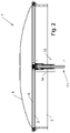
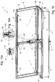
- FIG. 1 An overview of the smoke and heat exhaust ventilation system of the invention is shown in Figures from 1 to 10, where it is indicated as a whole by 1. Furthermore, Figures 1a, 1b , 3a , 10a, 10b represent enlarged details of the ventilation system shown in the overall views of Figures from 1 to 10.
- the smoke and heat exhaust ventilation system 1 which here below is referred to just with the term "ventilation system 1" for the sake of description simplicity, comprises a base 2 delimited by a counter frame 3 and arranged on the periphery of a through opening 4 made in the structure of a building and a cover 5 delimited by a frame 6 associated with the counter frame 3 of the base 2 by means of hinges 7.
- the through opening 4 places one or more rooms of the building in communication with the external environment and in case of fire the hinges 7 allow the cover 5 to rotate and open so that smoke and heat can be let out.
- the ventilation system 1 is provided with rotation means 10 suited to rotate the cover 5, which can be observed in particular in Figure 2 and in the successive Figures from 3 to 10, and which comprise a linear electric actuator 11, here below referred to just with the term “actuator 11" for the sake of description simplicity, having a power unit 11a which sets a stem 12 moving linearly inside a cylinder 13.
- rotation means 10 suited to rotate the cover 5, which can be observed in particular in Figure 2 and in the successive Figures from 3 to 10, and which comprise a linear electric actuator 11, here below referred to just with the term “actuator 11" for the sake of description simplicity, having a power unit 11a which sets a stem 12 moving linearly inside a cylinder 13.
- the rotation means 10 comprise also an articulation unit 14 operatively connected to the actuator 11 and comprising at least one first rod 15 visible in particular in Figures from 3 to 9 and connecting the head 16 of the stem 12 of the actuator 11 to the counter frame 3 of the base 2 and at least one second rod 17 connecting the cylinder 13 to the counter frame 3 of the base 2.
- first rods 15 placed side by side and parallel to each other and two second rods 17 also placed side by side and parallel to each other.
- the articulation unit 14 comprises also at least one connecting rod 18 that connects the head 16 of the stem 12 to the frame 6 of the cover 5.
- two connecting rods 18 are provided, placed side by side and parallel to each other.
- each connecting rod 18 has the first end 18a hinged to the head 16 of the stem 12 of the actuator 11 and the second end 18b hinged to the crosspiece 22 of the cover 5, which is included and fixed between two opposite sides 6a, 6b of the frame 6 that delimits the cover 5 peripherally.
- each first rod 15 has the first end 15a hinged to the head 16 of the stem 12 of the actuator 11, while each second rod 17 has the first end 17a hinged to the cylinder 13.
- each first rod 15 and the second end 17b of each second rod 17 are both connected to the counter frame 3 as they are hinged to a supporting bracket 19 that belongs to the crosspiece 20 of the counter frame 3, which is included between and fixed to the ends of two opposite sides 3a, 3b of the counter frame 3 of the base 2.
- each first rod 15 e the second end 17b of each second rod 17 are hinged to distinct points of the supporting bracket 19.
- each second rod 17 is arranged within the area perimetrically delimited by the base 2 and located below the plane X defined by the upper surface 3c of the counter frame 3 and the second end 15b of each first rod 15 is located above said plane X defined by the upper surface 3c of the counter frame 3.
- each first rod 15 and the second end 17b of each second rod 17 are aligned according to a direction Z that is inclined with respect to a vertical direction and incident on the plane X defined by the upper surface 3c of the counter frame 3.
- the articulation unit 14 also comprises at least one third rod 21, in the embodiment described herein two third rods 21 placed sided by side and parallel to each other, each of which connects a first rod 15 and a second rod 17 corresponding to it, and in each third rod 21 it is possible to identify a first end 21a hinged to an intermediate area of the first rod 15 and a second end 21b hinged to an intermediate area of the second rod 17.
- the actuator 11 and the articulation unit 14 are kinematically connected to each other, and when the actuator 11 is operated they cooperate with each other to rotate the cover 5, as illustrated below with reference to the figures.
- the ventilation system 1 comprises also coupling means 30 which are configured in such a way as to lock the cover 5 onto the counter frame 3 when the linear electric actuator 11 is in the rest condition and the frame 6, which delimits the cover 5, is arranged so that it faces and is in contact with the counter frame 3 of the base 2, as shown in Figure 3 .
- the coupling means 30 are configured to be also able to open the cover 5 after it has been released from the counter frame 3, which takes place automatically when the actuator 11 is activated, as described in greater detail below.
- the coupling means 30 comprise a revolving rod 31, visible also in the detail Figure 1b , associated with the cover 5 through supporting means, not indicated in the figures and supported by the frame 6, to which rod one or more hook-shaped coupling elements 33 are fixed and thus rotate rigidly with the revolving rod 31 when it is set rotating according to its longitudinal axis.
- the hook-shaped coupling elements 33 are three and two of them are arranged at the ends of the revolving rod 31, while one of them, instead, is arranged in an intermediate position on the revolving rod 31 itself, as shown in Figure 1b .
- hook-shaped coupling elements 33 can be present in any number and be arranged in any position along the revolving rod 31.
- Hook-shaped coupling counter elements 34 are also provided, which belong to the counter frame 3 of the base 2 and are configured to cooperate with the hook-shaped coupling elements 33.
- tie rod 35 which connects the rod 31 to a manoeuvring lever 36 associated with the cover 5 and visible in Figure 1a , which is configured to activate the tie rod 35 and release the hook-shaped coupling elements 33 from the hook-shaped coupling counter elements 34 when the thrusting action of the head 16 of the stem 12 of the actuator 11 acts on the manoeuvring lever 36 and makes it rotate, as can be observed in Figure 4 .
- the manoeuvring lever 36 is revolvingly associated with the cover 5 through a rotation pin 39a which constrains it to a fixed support 42 fixed to the crosspiece 22 of the cover 5 itself.
- manoeuvring lever 36 is provided with a reference plane 40 suited to come into contact with the head 16 of the stem 12 of the actuator 11, as can be observed in particular in Figure 4 .
- the tie rod 35 has the first end 35a fixed to a projecting coupling element 37 belonging to the revolving rod 31 and the second end 35b fixed to the manoeuvring lever 36 through a fork 38 and a pin 39 passing therethrough.
- the ends of the tie rod 35 can be connected to the revolving rod 31 and to the manoeuvring lever 36 even through means that are different from those described.
- the traction of the tie rod 35 in turn causes the rotation of the rod 31 around its longitudinal axis and of the hook-shaped coupling elements 33 connected to it, which release the respective hook-shaped coupling counter elements 34, thus allowing the opening of the cover 5 to start, as shown in Figure 4 .
- the revolving rod 31 is also associated with elastic means 41 visible in particular in Figure 1b , which are configured to make the rotation of the revolving rod 31 elastic, so that the hook-shaped coupling elements 33 spontaneously snap on the hook-shaped coupling counter elements 34 when the manoeuvring lever 36 is free from contact with the head 16 of the stem 12 of the actuator 11 and the frame 6 of the cover 5 is lowered so that it faces and rests against the counter frame 3 of the base 2, in the position which can be observed in Figure 3 .
- the elastic means 41 comprise a cylindrical spring 41a wound externally on the revolving rod 31 and having one end fixed to the same revolving rod 31 and the opposite end in contact with the crosspiece 22 of the cover 5.
- the actuator 11 If the actuator 11 is activated, when the head 16 of its stem 12 comes into contact with the reference plane 40 of the manoeuvring lever 36, the latter rotates around the rotation pin 39a and places the tie rod 35 under traction.
- the traction applied to the tie rod 35 overcomes the elastic force of the cylindrical spring 41a and causes the rotation of the revolving rod 31, which separates the hook-shaped coupling elements 33 from the corresponding hook-shaped coupling counter elements 34 and causes the cover 5 to start opening.
- the cover 5, which is not coupled with the counter frame 3 any longer, can be opened through the movement of the stem 12 of the actuator 11, passing through all the configurations shown in Figures from 4 to 8 until reaching the configuration of maximum opening, which corresponds to an angle of approximately 158° and is shown in Figure 9 .
- the head 16 of the stem 12 of the actuator 11 axially compresses the connecting rod 18 which, being rigid and indeformable and forming an angle ⁇ , always smaller than a straight angle, with the crosspiece 22 of the cover 5, starting from the configuration represented in Figure 3 is forced to rotate rigidly counter clockwise, thus moving its second end 18b upwards until reaching the configuration shown in Figure 7 , in which the cover 5 is open in a position that is substantially orthogonal to the base 2.
- Figures from 5 to 9 compare, for some identical opening angles of the cover 5, the lengthening C of the stem 12 in the case of the invention, in which its head 16 is connected to the crosspiece 22 through the connecting rod 18, with the lengthening C' that would result if the stem of the actuator, schematically represented with a thick broken line, had the head 16' directly connected to the crosspiece 22, as is the case in the ventilation systems known in the art.
- the connecting rod 18 and the third rod 21 operatively interact during the stroke of the stem 12 of the actuator 11 and produce a synergy which, in comparison with the known art and given the same opening angles of the covers, makes it possible to considerably reduce the stroke of the stem of the actuator being used.
- the articulation unit 14 is sized in such a way that when the cover 5 is opened by an angle of approximately 45°, as shown in Figure 5 , the second rod 17 is arranged in a substantially horizontal direction and the actuator 11, instead, is arranged in a substantially vertical direction.
- the head 16 of the stem 12 is arranged in the limit condition in which it is in contact with the manoeuvring lever 36 and directly exerts on the crosspiece 22 the maximum thrust to lift the cover 5.
- the head 16 of the stem 12 is not in contact with the manoeuvring lever 36 any longer, as can be observed for example in Figure 6 , and the connecting rod 18 transmits to the crosspiece 22 the thrust force required to lift the cover 5 which is produced by the lengthening of the stem 12 of the actuator 11.
- the rotation means 10 suited to rotate the cover 5, comprising the articulation unit 14 and the actuator 11 cooperating with each other, in the position shown in Figures from 1 to 10 are capable of moving a cover 5 of any size and can therefore be applied to any ventilation system of any size.
- the ventilation system 1 of the invention will be electrically connected to batteries fed by the electrical network in buffer mode and will be managed by a special control unit comprising sensors suited to detect smoke, heat, or other exceptional conditions so as to activate the opening of one or more ventilation systems 1 of the invention in case of fire or other anomalous conditions.
- the cover 5 can be of any type and shape, and can be made from any opaque, translucent, or transparent material.
- the ventilation system 1 of the invention can also serve as a skylight and be opened and closed as desired by the user to ventilate rooms. According to the above, it can be understood that the ventilation system 1 of the invention achieves all the set objects.
Landscapes
- Engineering & Computer Science (AREA)
- Mechanical Engineering (AREA)
- Architecture (AREA)
- Civil Engineering (AREA)
- Structural Engineering (AREA)
- Chemical & Material Sciences (AREA)
- Combustion & Propulsion (AREA)
- General Engineering & Computer Science (AREA)
- Air-Flow Control Members (AREA)
- Catching Or Destruction (AREA)
- Agricultural Chemicals And Associated Chemicals (AREA)
Applications Claiming Priority (1)
| Application Number | Priority Date | Filing Date | Title |
|---|---|---|---|
| IT102021000015236A IT202100015236A1 (it) | 2021-06-10 | 2021-06-10 | Evacuatore di fumo e di calore di tipo perfezionato |
Publications (2)
| Publication Number | Publication Date |
|---|---|
| EP4102017A1 true EP4102017A1 (fr) | 2022-12-14 |
| EP4102017B1 EP4102017B1 (fr) | 2024-10-23 |
Family
ID=77627348
Family Applications (1)
| Application Number | Title | Priority Date | Filing Date |
|---|---|---|---|
| EP21217324.9A Active EP4102017B1 (fr) | 2021-06-10 | 2021-12-23 | Système d'évacuation des fumées et de la chaleur |
Country Status (3)
| Country | Link |
|---|---|
| EP (1) | EP4102017B1 (fr) |
| ES (1) | ES3000113T3 (fr) |
| IT (1) | IT202100015236A1 (fr) |
Cited By (2)
| Publication number | Priority date | Publication date | Assignee | Title |
|---|---|---|---|---|
| CN119163181A (zh) * | 2024-11-21 | 2024-12-20 | 杭州博攀智能系统有限公司 | 一种适用于通信机房的消防电动排烟天窗及其使用方法 |
| WO2025036902A1 (fr) * | 2023-08-15 | 2025-02-20 | Hans Balle Holding Aps | Système de montage pour l'ouverture/la fermeture d'une partie pivotante d'une unité |
Citations (3)
| Publication number | Priority date | Publication date | Assignee | Title |
|---|---|---|---|---|
| EP0885341B1 (fr) * | 1996-03-05 | 2000-06-21 | Carlo Caoduro | Dispositif d'evacuation de fumee |
| DE202009001076U1 (de) * | 2009-01-28 | 2010-06-24 | Aumüller Aumatic GmbH | Beschlaganordnung |
| DE202010010494U1 (de) * | 2010-07-21 | 2011-12-05 | Jofo Pneumatik Gmbh | Rauchabzugsvorrichtung |
-
2021
- 2021-06-10 IT IT102021000015236A patent/IT202100015236A1/it unknown
- 2021-12-23 ES ES21217324T patent/ES3000113T3/es active Active
- 2021-12-23 EP EP21217324.9A patent/EP4102017B1/fr active Active
Patent Citations (3)
| Publication number | Priority date | Publication date | Assignee | Title |
|---|---|---|---|---|
| EP0885341B1 (fr) * | 1996-03-05 | 2000-06-21 | Carlo Caoduro | Dispositif d'evacuation de fumee |
| DE202009001076U1 (de) * | 2009-01-28 | 2010-06-24 | Aumüller Aumatic GmbH | Beschlaganordnung |
| DE202010010494U1 (de) * | 2010-07-21 | 2011-12-05 | Jofo Pneumatik Gmbh | Rauchabzugsvorrichtung |
Cited By (2)
| Publication number | Priority date | Publication date | Assignee | Title |
|---|---|---|---|---|
| WO2025036902A1 (fr) * | 2023-08-15 | 2025-02-20 | Hans Balle Holding Aps | Système de montage pour l'ouverture/la fermeture d'une partie pivotante d'une unité |
| CN119163181A (zh) * | 2024-11-21 | 2024-12-20 | 杭州博攀智能系统有限公司 | 一种适用于通信机房的消防电动排烟天窗及其使用方法 |
Also Published As
| Publication number | Publication date |
|---|---|
| EP4102017B1 (fr) | 2024-10-23 |
| ES3000113T3 (en) | 2025-02-27 |
| IT202100015236A1 (it) | 2022-12-10 |
Similar Documents
| Publication | Publication Date | Title |
|---|---|---|
| EP4102017B1 (fr) | Système d'évacuation des fumées et de la chaleur | |
| NO339545B1 (no) | Rulledør. | |
| US20200299114A1 (en) | Lifting apparatus for highly-mounted device and control method thereof | |
| CN107587811A (zh) | 一种基于移动通信的智能窗户及控制系统 | |
| JP2007515042A (ja) | 一方向ケーブル作動の非常停止装置 | |
| EP3702315B1 (fr) | Dispositif élévateur pour un équipement d'installation de grande hauteur et procédé de commande de ce dernier | |
| US5609378A (en) | Automatic crane hook safety latch | |
| CN111022995A (zh) | 一种高杆升降照明装置及控制系统 | |
| CN208089077U (zh) | 常开防火门闭门器联动控制装置 | |
| KR102107357B1 (ko) | 펄스 질량 엘리먼트를 갖는 전기 스위칭 디바이스용 커플링 엘리먼트 | |
| US7849906B2 (en) | Fast door with secure operation | |
| US5657197A (en) | Operative lightning protection system | |
| KR101594842B1 (ko) | 자연 채광 및 통풍 구조를 갖는 건축물 도어 | |
| CN112096045A (zh) | 一种防超载的吊篮 | |
| IE893768A1 (en) | A fire curtain installation | |
| CN215893788U (zh) | 紫外火焰检测器 | |
| KR101821995B1 (ko) | 그물 발사형 방범장치 | |
| JP4353071B2 (ja) | 天窓開閉装置 | |
| ES2202877T3 (es) | Medio de indicar desplazamientos de objetos desplazables. | |
| CN113720457B (zh) | 紫外火焰检测器 | |
| CN213844312U (zh) | 一种可防护的烟雾探测器 | |
| KR102358873B1 (ko) | 현관문 방범장치 | |
| KR102049397B1 (ko) | 타워 크레인용 안전장치 | |
| CN111395522B (zh) | 一种气承式膜结构中钢缆与膜片地基的可调式连接结构 | |
| CN112193398A (zh) | 一种防火通风筒 |
Legal Events
| Date | Code | Title | Description |
|---|---|---|---|
| PUAI | Public reference made under article 153(3) epc to a published international application that has entered the european phase |
Free format text: ORIGINAL CODE: 0009012 |
|
| STAA | Information on the status of an ep patent application or granted ep patent |
Free format text: STATUS: THE APPLICATION HAS BEEN PUBLISHED |
|
| AK | Designated contracting states |
Kind code of ref document: A1 Designated state(s): AL AT BE BG CH CY CZ DE DK EE ES FI FR GB GR HR HU IE IS IT LI LT LU LV MC MK MT NL NO PL PT RO RS SE SI SK SM TR |
|
| STAA | Information on the status of an ep patent application or granted ep patent |
Free format text: STATUS: REQUEST FOR EXAMINATION WAS MADE |
|
| 17P | Request for examination filed |
Effective date: 20221228 |
|
| RBV | Designated contracting states (corrected) |
Designated state(s): AL AT BE BG CH CY CZ DE DK EE ES FI FR GB GR HR HU IE IS IT LI LT LU LV MC MK MT NL NO PL PT RO RS SE SI SK SM TR |
|
| STAA | Information on the status of an ep patent application or granted ep patent |
Free format text: STATUS: EXAMINATION IS IN PROGRESS |
|
| 17Q | First examination report despatched |
Effective date: 20240213 |
|
| GRAP | Despatch of communication of intention to grant a patent |
Free format text: ORIGINAL CODE: EPIDOSNIGR1 |
|
| STAA | Information on the status of an ep patent application or granted ep patent |
Free format text: STATUS: GRANT OF PATENT IS INTENDED |
|
| RIC1 | Information provided on ipc code assigned before grant |
Ipc: F24F 11/34 20180101ALI20240426BHEP Ipc: E04D 13/035 20060101ALI20240426BHEP Ipc: E05F 15/63 20150101ALI20240426BHEP Ipc: E05F 15/616 20150101ALI20240426BHEP Ipc: E05D 15/40 20060101AFI20240426BHEP |
|
| INTG | Intention to grant announced |
Effective date: 20240514 |
|
| RAP3 | Party data changed (applicant data changed or rights of an application transferred) |
Owner name: CAODURO, CARLO Owner name: CAODURO, PAOLO |
|
| RIN1 | Information on inventor provided before grant (corrected) |
Inventor name: CAODURO, CARLO Inventor name: CAODURO, PAOLO |
|
| GRAS | Grant fee paid |
Free format text: ORIGINAL CODE: EPIDOSNIGR3 |
|
| GRAA | (expected) grant |
Free format text: ORIGINAL CODE: 0009210 |
|
| STAA | Information on the status of an ep patent application or granted ep patent |
Free format text: STATUS: THE PATENT HAS BEEN GRANTED |
|
| AK | Designated contracting states |
Kind code of ref document: B1 Designated state(s): AL AT BE BG CH CY CZ DE DK EE ES FI FR GB GR HR HU IE IS IT LI LT LU LV MC MK MT NL NO PL PT RO RS SE SI SK SM TR |
|
| REG | Reference to a national code |
Ref country code: GB Ref legal event code: FG4D |
|
| REG | Reference to a national code |
Ref country code: CH Ref legal event code: EP |
|
| REG | Reference to a national code |
Ref country code: DE Ref legal event code: R096 Ref document number: 602021020615 Country of ref document: DE |
|
| REG | Reference to a national code |
Ref country code: IE Ref legal event code: FG4D |
|
| P01 | Opt-out of the competence of the unified patent court (upc) registered |
Free format text: CASE NUMBER: APP_63491/2024 Effective date: 20241129 |
|
| REG | Reference to a national code |
Ref country code: LT Ref legal event code: MG9D |
|
| REG | Reference to a national code |
Ref country code: NL Ref legal event code: MP Effective date: 20241023 |
|
| REG | Reference to a national code |
Ref country code: ES Ref legal event code: FG2A Ref document number: 3000113 Country of ref document: ES Kind code of ref document: T3 Effective date: 20250227 |
|
| REG | Reference to a national code |
Ref country code: GR Ref legal event code: EP Ref document number: 20240402984 Country of ref document: GR Effective date: 20250211 |
|
| REG | Reference to a national code |
Ref country code: AT Ref legal event code: MK05 Ref document number: 1734967 Country of ref document: AT Kind code of ref document: T Effective date: 20241023 |
|
| PG25 | Lapsed in a contracting state [announced via postgrant information from national office to epo] |
Ref country code: NL Free format text: LAPSE BECAUSE OF FAILURE TO SUBMIT A TRANSLATION OF THE DESCRIPTION OR TO PAY THE FEE WITHIN THE PRESCRIBED TIME-LIMIT Effective date: 20241023 |
|
| PG25 | Lapsed in a contracting state [announced via postgrant information from national office to epo] |
Ref country code: NL Free format text: LAPSE BECAUSE OF FAILURE TO SUBMIT A TRANSLATION OF THE DESCRIPTION OR TO PAY THE FEE WITHIN THE PRESCRIBED TIME-LIMIT Effective date: 20241023 |
|
| PG25 | Lapsed in a contracting state [announced via postgrant information from national office to epo] |
Ref country code: HR Free format text: LAPSE BECAUSE OF FAILURE TO SUBMIT A TRANSLATION OF THE DESCRIPTION OR TO PAY THE FEE WITHIN THE PRESCRIBED TIME-LIMIT Effective date: 20241023 Ref country code: PT Free format text: LAPSE BECAUSE OF FAILURE TO SUBMIT A TRANSLATION OF THE DESCRIPTION OR TO PAY THE FEE WITHIN THE PRESCRIBED TIME-LIMIT Effective date: 20250224 Ref country code: IS Free format text: LAPSE BECAUSE OF FAILURE TO SUBMIT A TRANSLATION OF THE DESCRIPTION OR TO PAY THE FEE WITHIN THE PRESCRIBED TIME-LIMIT Effective date: 20250223 |
|
| PG25 | Lapsed in a contracting state [announced via postgrant information from national office to epo] |
Ref country code: FI Free format text: LAPSE BECAUSE OF FAILURE TO SUBMIT A TRANSLATION OF THE DESCRIPTION OR TO PAY THE FEE WITHIN THE PRESCRIBED TIME-LIMIT Effective date: 20241023 |
|
| PG25 | Lapsed in a contracting state [announced via postgrant information from national office to epo] |
Ref country code: BG Free format text: LAPSE BECAUSE OF FAILURE TO SUBMIT A TRANSLATION OF THE DESCRIPTION OR TO PAY THE FEE WITHIN THE PRESCRIBED TIME-LIMIT Effective date: 20241023 |
|
| PG25 | Lapsed in a contracting state [announced via postgrant information from national office to epo] |
Ref country code: NO Free format text: LAPSE BECAUSE OF FAILURE TO SUBMIT A TRANSLATION OF THE DESCRIPTION OR TO PAY THE FEE WITHIN THE PRESCRIBED TIME-LIMIT Effective date: 20250123 |
|
| PG25 | Lapsed in a contracting state [announced via postgrant information from national office to epo] |
Ref country code: LV Free format text: LAPSE BECAUSE OF FAILURE TO SUBMIT A TRANSLATION OF THE DESCRIPTION OR TO PAY THE FEE WITHIN THE PRESCRIBED TIME-LIMIT Effective date: 20241023 Ref country code: AT Free format text: LAPSE BECAUSE OF FAILURE TO SUBMIT A TRANSLATION OF THE DESCRIPTION OR TO PAY THE FEE WITHIN THE PRESCRIBED TIME-LIMIT Effective date: 20241023 |
|
| PG25 | Lapsed in a contracting state [announced via postgrant information from national office to epo] |
Ref country code: PL Free format text: LAPSE BECAUSE OF FAILURE TO SUBMIT A TRANSLATION OF THE DESCRIPTION OR TO PAY THE FEE WITHIN THE PRESCRIBED TIME-LIMIT Effective date: 20241023 |
|
| PG25 | Lapsed in a contracting state [announced via postgrant information from national office to epo] |
Ref country code: RS Free format text: LAPSE BECAUSE OF FAILURE TO SUBMIT A TRANSLATION OF THE DESCRIPTION OR TO PAY THE FEE WITHIN THE PRESCRIBED TIME-LIMIT Effective date: 20250123 |
|
| REG | Reference to a national code |
Ref country code: DE Ref legal event code: R119 Ref document number: 602021020615 Country of ref document: DE |
|
| PG25 | Lapsed in a contracting state [announced via postgrant information from national office to epo] |
Ref country code: SM Free format text: LAPSE BECAUSE OF FAILURE TO SUBMIT A TRANSLATION OF THE DESCRIPTION OR TO PAY THE FEE WITHIN THE PRESCRIBED TIME-LIMIT Effective date: 20241023 |
|
| PG25 | Lapsed in a contracting state [announced via postgrant information from national office to epo] |
Ref country code: MC Free format text: LAPSE BECAUSE OF FAILURE TO SUBMIT A TRANSLATION OF THE DESCRIPTION OR TO PAY THE FEE WITHIN THE PRESCRIBED TIME-LIMIT Effective date: 20241023 |
|
| PG25 | Lapsed in a contracting state [announced via postgrant information from national office to epo] |
Ref country code: DK Free format text: LAPSE BECAUSE OF FAILURE TO SUBMIT A TRANSLATION OF THE DESCRIPTION OR TO PAY THE FEE WITHIN THE PRESCRIBED TIME-LIMIT Effective date: 20241023 |
|
| PG25 | Lapsed in a contracting state [announced via postgrant information from national office to epo] |
Ref country code: EE Free format text: LAPSE BECAUSE OF FAILURE TO SUBMIT A TRANSLATION OF THE DESCRIPTION OR TO PAY THE FEE WITHIN THE PRESCRIBED TIME-LIMIT Effective date: 20241023 |
|
| PG25 | Lapsed in a contracting state [announced via postgrant information from national office to epo] |
Ref country code: RO Free format text: LAPSE BECAUSE OF FAILURE TO SUBMIT A TRANSLATION OF THE DESCRIPTION OR TO PAY THE FEE WITHIN THE PRESCRIBED TIME-LIMIT Effective date: 20241023 |
|
| PG25 | Lapsed in a contracting state [announced via postgrant information from national office to epo] |
Ref country code: SK Free format text: LAPSE BECAUSE OF FAILURE TO SUBMIT A TRANSLATION OF THE DESCRIPTION OR TO PAY THE FEE WITHIN THE PRESCRIBED TIME-LIMIT Effective date: 20241023 |
|
| PG25 | Lapsed in a contracting state [announced via postgrant information from national office to epo] |
Ref country code: CZ Free format text: LAPSE BECAUSE OF FAILURE TO SUBMIT A TRANSLATION OF THE DESCRIPTION OR TO PAY THE FEE WITHIN THE PRESCRIBED TIME-LIMIT Effective date: 20241023 |
|
| REG | Reference to a national code |
Ref country code: CH Ref legal event code: PL |
|
| PG25 | Lapsed in a contracting state [announced via postgrant information from national office to epo] |
Ref country code: LU Free format text: LAPSE BECAUSE OF NON-PAYMENT OF DUE FEES Effective date: 20241223 |
|
| PLBE | No opposition filed within time limit |
Free format text: ORIGINAL CODE: 0009261 |
|
| STAA | Information on the status of an ep patent application or granted ep patent |
Free format text: STATUS: NO OPPOSITION FILED WITHIN TIME LIMIT |
|
| PG25 | Lapsed in a contracting state [announced via postgrant information from national office to epo] |
Ref country code: SE Free format text: LAPSE BECAUSE OF FAILURE TO SUBMIT A TRANSLATION OF THE DESCRIPTION OR TO PAY THE FEE WITHIN THE PRESCRIBED TIME-LIMIT Effective date: 20241023 |
|
| 26N | No opposition filed |
Effective date: 20250724 |
|
| REG | Reference to a national code |
Ref country code: BE Ref legal event code: MM Effective date: 20241231 |
|
| PG25 | Lapsed in a contracting state [announced via postgrant information from national office to epo] |
Ref country code: DE Free format text: LAPSE BECAUSE OF NON-PAYMENT OF DUE FEES Effective date: 20250701 |
|
| PGFP | Annual fee paid to national office [announced via postgrant information from national office to epo] |
Ref country code: IT Payment date: 20250911 Year of fee payment: 5 |
|
| PG25 | Lapsed in a contracting state [announced via postgrant information from national office to epo] |
Ref country code: BE Free format text: LAPSE BECAUSE OF NON-PAYMENT OF DUE FEES Effective date: 20241231 |
|
| PG25 | Lapsed in a contracting state [announced via postgrant information from national office to epo] |
Ref country code: FR Free format text: LAPSE BECAUSE OF NON-PAYMENT OF DUE FEES Effective date: 20241223 |
|
| PG25 | Lapsed in a contracting state [announced via postgrant information from national office to epo] |
Ref country code: CH Free format text: LAPSE BECAUSE OF NON-PAYMENT OF DUE FEES Effective date: 20241231 |
|
| PG25 | Lapsed in a contracting state [announced via postgrant information from national office to epo] |
Ref country code: IE Free format text: LAPSE BECAUSE OF NON-PAYMENT OF DUE FEES Effective date: 20241223 |
|
| REG | Reference to a national code |
Ref country code: CH Ref legal event code: U11 Free format text: ST27 STATUS EVENT CODE: U-0-0-U10-U11 (AS PROVIDED BY THE NATIONAL OFFICE) Effective date: 20260101 |
|
| PGFP | Annual fee paid to national office [announced via postgrant information from national office to epo] |
Ref country code: GR Payment date: 20251222 Year of fee payment: 5 |
|
| PGFP | Annual fee paid to national office [announced via postgrant information from national office to epo] |
Ref country code: ES Payment date: 20260130 Year of fee payment: 5 |
|
| PGFP | Annual fee paid to national office [announced via postgrant information from national office to epo] |
Ref country code: CH Payment date: 20260101 Year of fee payment: 5 |