EP4102293B1 - Caméra et procédé de détection des objets se déplaçant dans une zone de détection - Google Patents
Caméra et procédé de détection des objets se déplaçant dans une zone de détection Download PDFInfo
- Publication number
- EP4102293B1 EP4102293B1 EP22171385.2A EP22171385A EP4102293B1 EP 4102293 B1 EP4102293 B1 EP 4102293B1 EP 22171385 A EP22171385 A EP 22171385A EP 4102293 B1 EP4102293 B1 EP 4102293B1
- Authority
- EP
- European Patent Office
- Prior art keywords
- camera
- distance
- aperture
- diaphragm
- image data
- Prior art date
- Legal status (The legal status is an assumption and is not a legal conclusion. Google has not performed a legal analysis and makes no representation as to the accuracy of the status listed.)
- Active
Links
Images

Classifications
-
- H—ELECTRICITY
- H04—ELECTRIC COMMUNICATION TECHNIQUE
- H04N—PICTORIAL COMMUNICATION, e.g. TELEVISION
- H04N23/00—Cameras or camera modules comprising electronic image sensors; Control thereof
- H04N23/95—Computational photography systems, e.g. light-field imaging systems
- H04N23/958—Computational photography systems, e.g. light-field imaging systems for extended depth of field imaging
- H04N23/959—Computational photography systems, e.g. light-field imaging systems for extended depth of field imaging by adjusting depth of field during image capture, e.g. maximising or setting range based on scene characteristics
-
- G—PHYSICS
- G03—PHOTOGRAPHY; CINEMATOGRAPHY; ANALOGOUS TECHNIQUES USING WAVES OTHER THAN OPTICAL WAVES; ELECTROGRAPHY; HOLOGRAPHY
- G03B—APPARATUS OR ARRANGEMENTS FOR TAKING PHOTOGRAPHS OR FOR PROJECTING OR VIEWING THEM; APPARATUS OR ARRANGEMENTS EMPLOYING ANALOGOUS TECHNIQUES USING WAVES OTHER THAN OPTICAL WAVES; ACCESSORIES THEREFOR
- G03B7/00—Control of exposure by setting shutters, diaphragms or filters, separately or conjointly
- G03B7/006—Control of exposure by setting shutters, diaphragms or filters, separately or conjointly setting of both diaphragm and distance
-
- G—PHYSICS
- G01—MEASURING; TESTING
- G01S—RADIO DIRECTION-FINDING; RADIO NAVIGATION; DETERMINING DISTANCE OR VELOCITY BY USE OF RADIO WAVES; LOCATING OR PRESENCE-DETECTING BY USE OF THE REFLECTION OR RERADIATION OF RADIO WAVES; ANALOGOUS ARRANGEMENTS USING OTHER WAVES
- G01S17/00—Systems using the reflection or reradiation of electromagnetic waves other than radio waves, e.g. lidar systems
- G01S17/02—Systems using the reflection of electromagnetic waves other than radio waves
- G01S17/06—Systems determining position data of a target
- G01S17/08—Systems determining position data of a target for measuring distance only
-
- G—PHYSICS
- G01—MEASURING; TESTING
- G01S—RADIO DIRECTION-FINDING; RADIO NAVIGATION; DETERMINING DISTANCE OR VELOCITY BY USE OF RADIO WAVES; LOCATING OR PRESENCE-DETECTING BY USE OF THE REFLECTION OR RERADIATION OF RADIO WAVES; ANALOGOUS ARRANGEMENTS USING OTHER WAVES
- G01S17/00—Systems using the reflection or reradiation of electromagnetic waves other than radio waves, e.g. lidar systems
- G01S17/88—Lidar systems specially adapted for specific applications
- G01S17/89—Lidar systems specially adapted for specific applications for mapping or imaging
- G01S17/894—Three-dimensional [3D] imaging with simultaneous measurement of time-of-flight at a two-dimensional [2D] array of receiver pixels, e.g. time-of-flight cameras or flash lidar
-
- G—PHYSICS
- G01—MEASURING; TESTING
- G01S—RADIO DIRECTION-FINDING; RADIO NAVIGATION; DETERMINING DISTANCE OR VELOCITY BY USE OF RADIO WAVES; LOCATING OR PRESENCE-DETECTING BY USE OF THE REFLECTION OR RERADIATION OF RADIO WAVES; ANALOGOUS ARRANGEMENTS USING OTHER WAVES
- G01S7/00—Details of systems according to groups G01S13/00, G01S15/00, G01S17/00
- G01S7/48—Details of systems according to groups G01S13/00, G01S15/00, G01S17/00 of systems according to group G01S17/00
- G01S7/497—Means for monitoring or calibrating
-
- G—PHYSICS
- G03—PHOTOGRAPHY; CINEMATOGRAPHY; ANALOGOUS TECHNIQUES USING WAVES OTHER THAN OPTICAL WAVES; ELECTROGRAPHY; HOLOGRAPHY
- G03B—APPARATUS OR ARRANGEMENTS FOR TAKING PHOTOGRAPHS OR FOR PROJECTING OR VIEWING THEM; APPARATUS OR ARRANGEMENTS EMPLOYING ANALOGOUS TECHNIQUES USING WAVES OTHER THAN OPTICAL WAVES; ACCESSORIES THEREFOR
- G03B13/00—Viewfinders; Focusing aids for cameras; Means for focusing for cameras; Autofocus systems for cameras
- G03B13/18—Focusing aids
- G03B13/20—Rangefinders coupled with focusing arrangements, e.g. adjustment of rangefinder automatically focusing camera
-
- G—PHYSICS
- G03—PHOTOGRAPHY; CINEMATOGRAPHY; ANALOGOUS TECHNIQUES USING WAVES OTHER THAN OPTICAL WAVES; ELECTROGRAPHY; HOLOGRAPHY
- G03B—APPARATUS OR ARRANGEMENTS FOR TAKING PHOTOGRAPHS OR FOR PROJECTING OR VIEWING THEM; APPARATUS OR ARRANGEMENTS EMPLOYING ANALOGOUS TECHNIQUES USING WAVES OTHER THAN OPTICAL WAVES; ACCESSORIES THEREFOR
- G03B13/00—Viewfinders; Focusing aids for cameras; Means for focusing for cameras; Autofocus systems for cameras
- G03B13/32—Means for focusing
-
- G—PHYSICS
- G03—PHOTOGRAPHY; CINEMATOGRAPHY; ANALOGOUS TECHNIQUES USING WAVES OTHER THAN OPTICAL WAVES; ELECTROGRAPHY; HOLOGRAPHY
- G03B—APPARATUS OR ARRANGEMENTS FOR TAKING PHOTOGRAPHS OR FOR PROJECTING OR VIEWING THEM; APPARATUS OR ARRANGEMENTS EMPLOYING ANALOGOUS TECHNIQUES USING WAVES OTHER THAN OPTICAL WAVES; ACCESSORIES THEREFOR
- G03B9/00—Exposure-making shutters; Diaphragms
- G03B9/02—Diaphragms
-
- G—PHYSICS
- G06—COMPUTING OR CALCULATING; COUNTING
- G06V—IMAGE OR VIDEO RECOGNITION OR UNDERSTANDING
- G06V30/00—Character recognition; Recognising digital ink; Document-oriented image-based pattern recognition
- G06V30/10—Character recognition
- G06V30/14—Image acquisition
- G06V30/1437—Sensor details, e.g. position, configuration or special lenses
-
- G—PHYSICS
- G06—COMPUTING OR CALCULATING; COUNTING
- G06V—IMAGE OR VIDEO RECOGNITION OR UNDERSTANDING
- G06V30/00—Character recognition; Recognising digital ink; Document-oriented image-based pattern recognition
- G06V30/40—Document-oriented image-based pattern recognition
- G06V30/42—Document-oriented image-based pattern recognition based on the type of document
- G06V30/424—Postal images, e.g. labels or addresses on parcels or postal envelopes
-
- H—ELECTRICITY
- H04—ELECTRIC COMMUNICATION TECHNIQUE
- H04N—PICTORIAL COMMUNICATION, e.g. TELEVISION
- H04N23/00—Cameras or camera modules comprising electronic image sensors; Control thereof
- H04N23/60—Control of cameras or camera modules
- H04N23/61—Control of cameras or camera modules based on recognised objects
-
- H—ELECTRICITY
- H04—ELECTRIC COMMUNICATION TECHNIQUE
- H04N—PICTORIAL COMMUNICATION, e.g. TELEVISION
- H04N23/00—Cameras or camera modules comprising electronic image sensors; Control thereof
- H04N23/60—Control of cameras or camera modules
- H04N23/67—Focus control based on electronic image sensor signals
- H04N23/671—Focus control based on electronic image sensor signals in combination with active ranging signals, e.g. using light or sound signals emitted toward objects
-
- H—ELECTRICITY
- H04—ELECTRIC COMMUNICATION TECHNIQUE
- H04N—PICTORIAL COMMUNICATION, e.g. TELEVISION
- H04N23/00—Cameras or camera modules comprising electronic image sensors; Control thereof
- H04N23/70—Circuitry for compensating brightness variation in the scene
- H04N23/75—Circuitry for compensating brightness variation in the scene by influencing optical camera components
Definitions
- the invention relates to a camera and a method for detecting objects moving through a detection area according to the preamble of claims 1 and 14, respectively.
- cameras are used in a variety of ways to automatically record object properties, for example to inspect or measure objects. Images of the object are recorded and evaluated according to the task using image processing methods. Another use of cameras is to read codes. With the help of an image sensor, objects with the codes on them are recorded, the code areas are identified in the images and then decoded. Camera-based code readers can also easily handle other types of code than one-dimensional barcodes, which, like a matrix code, are also two-dimensional and provide more information.
- OCR Optical Character Recognition
- handwriting is basically a reading of codes. Typical areas of application for code readers are supermarket checkouts, automatic parcel identification, sorting of postal items, baggage handling in airports and other logistics applications.
- a common capture situation is mounting the camera over a conveyor belt.
- the camera takes pictures during the relative movement of the object stream on the conveyor belt and initiates further processing steps depending on the object properties obtained.
- processing steps consist, for example, in the further processing adapted to the specific object on a machine that acts on the conveyed objects, or in a change in the object flow by certain Objects are ejected from the object stream as part of a quality control or the object stream is sorted into several sub-object streams. If the camera is a camera-based code reader, the objects are identified based on the attached codes for correct sorting or similar processing steps.
- An aperture is usually built into the lens of the camera.
- the aperture conventionally remains constant in the applications described.
- An adjustment of the aperture may only take place once, for example during the installation process, in order to find a suitable constant aperture for operation.
- Adjustable apertures have long been used in the field of photography. There are now a variety of technical implementations for variable apertures.
- a classic iris diaphragm can be motor-actuated.
- An LCD display with discrete pixels that can be switched from opaque to transparent enables a screen effect with different opening radii.
- the use of microfluids is conceivable, whereby an opaque liquid is actuated via electrowetting in order to be positioned in various discrete radii on a transparent disc in the shape of a ring.
- Another possible implementation is based on a transparent membrane that bulges under negative pressure and displaces an opaque liquid. This creates a round, transparent opening at the contact surface of the membrane and a glass substrate.
- a distance sensor based on a time-of-flight method (TOF, Time of Flight) is integrated into a camera.
- TOF Time of Flight
- a height profile is measured with it, and various functions are implemented on the basis of this.
- One of these functions is the adjustment of the focal position of a receiving lens.
- An aperture in the receiving lens is mentioned only once, and this aperture is not adjustable.
- the measurement duration of such a distance sensor is adjusted so that the distance value is measured with at most a measurement error at which the correspondingly selected focus position is sufficient for a required image sharpness.
- the DE 10 2020 109 929 B3 If the available focusing time is too short, only adjusts to a focus position that can be reached in time and still has sufficient image sharpness, which deviates from the optimal focus position according to the distance measurement.
- the influence of the aperture on the depth of field should be expressly excluded in each case by fixing or optimal setting.
- the U.S. 7,025,271 B2 describes a camera-based code reader with a selectable depth of field, which is preferably designed as a hand-held device.
- An optical element is switched between a transmissive and a reflective state in order to guide the received light onto a first or second lens arrangement, the lens arrangements having different depths of field from one another.
- An adjustable aperture arrangement is mentioned in the introduction, and it is noted that the depth of field increases with a smaller aperture diameter and vice versa. But that is not explained in detail.
- the U.S. 2010/0310246 A1 deals with aperture selection in photography.
- the aperture is set either manually or automatically to avoid over- or underexposure.
- the US 2012/0229674 A1 accesses a database to run a depth-of-field optimization algorithm.
- the depth of field can be modified by changing the aperture.
- the U.S. 2017/0310867 A1 discloses a control method for an aperture of an optical device.
- the aperture is adjusted according to a focus position by means of a drive and electronic control.
- JP 2011 151 448 A an imaging device with a variable aperture is described.
- the aperture is adjusted to affect the depth of field.
- a camera and a method for detecting objects moving through a detection area according to claims 1 and 14, respectively.
- the camera and objects are in relative motion to each other, which means that the objects to be recorded move into or through the detection range of the camera.
- An image sensor records images or image data of the detection area and thus of an object located there.
- a receiving optics of the camera refers to a receiving objective which, depending on the quality requirements, has one or more lenses and other optical elements as well as an adjustable diaphragm whose diaphragm opening or aperture can be changed by control. The depth of field results from the properties of the receiving optics and the respective Aperture adjustment.
- a control and evaluation unit reads out the image data in order, for example, to preprocess them, evaluate them, store them or output them at an interface. It is also responsible for controlling the aperture and thus for its appropriate settings.
- the control and evaluation unit can have a common module or separate modules that take care of the aperture setting on the one hand and the other tasks in the camera, such as processing the image data, on the other.
- the invention is based on the basic idea of dynamically adapting the aperture setting from object to object.
- a suitable aperture ensures that each object is recorded within a depth of field and that the recorded image or the image data thus achieve the required image sharpness.
- the invention has the advantage that the quality of the image data is increased by individually adjusting the aperture for each object. This enables a simpler configuration of the receiving optics elsewhere, for example a fixed focus system, or alternatively it meets particularly high demands on the image data.
- An adjustable diaphragm is available as a component and the invention can therefore be implemented easily and comparatively inexpensively.
- the depth of field is preferably determined from application-specific requirements.
- the term depth of field is thus expressly used in a broader sense than just its original optical or physical sense.
- the physical depth of field depends on lens constants and settings of the receiving optics. In practice, however, it is not primarily a question of objective image sharpness criteria, but rather the question of whether the image data will allow the intended evaluation. This can be assessed very differently from application to application.
- the aperture setting should preferably ensure that the object is recorded in a depth of field according to this application-related understanding.
- the control and evaluation unit is preferably designed to read a code content of a code on the object using the image data.
- the camera thus becomes a camera-based code reader for barcodes and/or 2D codes according to various Standards, possibly also for text recognition (OCR, Optical Character Reading).
- OCR Optical Character Reading
- a segmentation it is even more preferable for a segmentation to be carried out, with which areas of interest (ROI, region of interest) are identified as code candidates.
- the object is preferably recorded in the depth of field when a code can be read from the recorded image data.
- This is an example of the application specific depth of field requirements discussed above.
- the image should be sharp enough to read a code. This is a purely practice-related criterion, which does not depend on abstract quality or image sharpness dimensions of the image data, but purely pragmatically on the question of whether the task of reading the code can be fulfilled.
- a maximum decoding or reading rate is achieved by dynamic adjustment of the aperture.
- the expectation of when the image sharpness will be sufficient to read a code can be simulated in advance or generated experimentally. For example, codes are presented to the camera at different intervals under typical conditions, for example with regard to ambient light and print quality, in order to find out at which aperture settings a code is still read (GoodRead) or is no longer read (No-Read).
- the required depth of field preferably depends on a code type, a module size, for example specified in pixels per module, and/or a decoding method. Again, this is not just about the physical depth of field, but about practical requirements and thus the further understanding of an application-specific depth of field. Whether a code can be read is determined in particular by the parameters or settings mentioned. Some code types are simpler and can therefore also be read from comparatively inferior image data, while some code types are particularly demanding. If more pixels are available per module, code reading is easier than with a small module size. The exposure, both in terms of integration time and the lighting scenario of an optional active lighting, plays its part. Some decoders handle lower picture quality better than others. There can be interactions between the parameters mentioned, which affect the required depth of field.
- the camera has a distance sensor for measuring a distance value to an object.
- the distance value serves as a criterion for a required depth of field, and the control and evaluation unit can adjust the aperture accordingly.
- the distance value can be converted into a height of the object above this reference plane, knowing the mounting position. Therefore, in the following, object height and distance are used interchangeably in some places.
- the distance sensor is preferably integrated into the camera. This keeps the system compact and encapsulated.
- the control and evaluation unit has easy internal access to the distance sensor.
- the distance sensor is preferably designed as an optoelectronic distance sensor, in particular according to the principle of the time-of-flight method. Such distance sensors are available as finished chips or modules.
- the distance sensor particularly preferably has a multiplicity of SPADs (single-photon avalanche photodiodes), which each measure a single light propagation time via TDCs (time-to-digital converter).
- the control and evaluation unit is designed to set the aperture for an object as a function of a distance value measured for the object.
- the dynamic coupling of the aperture setting to the distance value of the individual objects ensures that the respective object is recorded within a required depth of field, depth of field preferably being to be understood in the application-specific sense discussed several times.
- the control and evaluation unit preferably sets the aperture for an object based on a function of the required aperture as a function of the distance from an object.
- a function aperture (distance) or aperture (object height) is thus stored, for example in a memory of the camera or the control and evaluation unit.
- This function can be given as an analytic function or as an approximation, for example as a step function, as a total or piecewise linear or polynomial function, or as a lookup table (LUT).
- the control and evaluation unit is preferably designed for a learning process in which an object is arranged at a distance, image data is recorded, an image focus is checked and the aperture is adjusted until a suitable aperture setting for this distance is found.
- This allows the appropriate aperture to be calibrated or taught for a specific distance, which should then be set dynamically during operation for an object at this distance.
- the criterion for the appropriate aperture is, for example, maximum, optimal or still sufficient image sharpness or an application-specific requirement, such as reading a code.
- the teaching can be repeated for at least one other object at the same distance and then averaged, for example. Further iterations place an object or successively several objects at different distances in order to find the appropriate aperture setting for it, or in a preferred embodiment several values of the function aperture(distance). An interpolation can be used instead of the resulting step function.
- the control and evaluation unit is preferably designed to set the aperture to a maximum aperture for an object at a distance corresponding to the focal position and to increasingly close the aperture for deviating, in particular smaller, distances. If an object is located at a distance that corresponds to the focus position, the aperture does not have to contribute to an extended depth of field. The maximum opening of the aperture can still be limited by other boundary conditions such as overexposure. In deviant distances, the depth of field can be extended by narrowing the aperture. This behavior can be represented by the aperture(distance) function. In a fixed focus system, the focus position is preferably set to a maximum distance. The aperture is then open for a distant object, the depth of field is small, and images are taken with a lot of light and good resolution.
- the aperture is reduced and the depth of field increases.
- the reduced incidence of light is actually desirable because of the distance-dependent dynamic behavior, ie the typical 1/r 2 characteristic.
- the poorer resolution is acceptable since the structures and in particular the module sizes increase with increasing proximity.
- the aperture is preferably installed in the receiving optics or placed on the receiving optics.
- the adjustable aperture can replace the previous fixed aperture in a lens design. It is conceivable to integrate a diaphragm together with a lens. Alternatively, the adjustable aperture is placed on the lens at the front towards the scenery or at the rear towards the image sensor.
- FIG 1 shows a schematic sectional view of a camera 10.
- Received light 12 from a detection area 14 impinges on receiving optics 16, which guides the received light 12 onto an image sensor 18.
- the optical elements of the receiving optics 16 are preferably designed as an objective made up of a plurality of lenses and other optical elements such as diaphragms, prisms and the like, but are represented here by just one lens for the sake of simplicity.
- the receiving optics 16 has a fixed focal position (fixed focus).
- An adjustable aperture 17 is assigned to the receiving optics.
- the adjustment principle can be based on a wide variety of technologies, in particular a motor-actuated iris diaphragm, an LCD display, an opaque liquid using the electrowetting effect, or a transparent membrane, as briefly discussed in the introduction. In the following, only the functional aspect is considered that the aperture of the adjustable aperture 17 can be changed by electronic control.
- the adjustable aperture can be installed in the receiving optics 16 or attached to the image sensor 18 or to the detection area 14 .
- the adjustable diaphragm 17 preferably produces a round diaphragm opening, but other geometries are also conceivable.
- the camera 10 comprises an optional lighting unit 22, which is shown in figure 1 is shown in the form of a simple light source and without transmission optics.
- a plurality of light sources such as LEDs or laser diodes, are arranged, for example, in a ring around the reception path, which are also multicolored and can be controlled in groups or individually in order to adjust parameters of the lighting unit 22 such as its color, intensity and direction.
- the lighting unit 22 can be an external component or can be omitted entirely; in the latter case, the camera 10 only works with the ambient light.
- the camera 10 has an optoelectronic distance sensor 24 which measures distances to objects in the capturing area 14 using a time-of-flight method (TOF, Time of Flight).
- the distance sensor 24 includes a TOF light transmitter 26 with TOF transmission optics 28 and a TOF light receiver 30 with TOF reception optics 32.
- a TOF light signal 34 is thus emitted and received again.
- a light propagation time measuring unit 36 determines the propagation time of the TOF light signal 34 and from this the distance to an object at which the TOF light signal 34 was reflected.
- the TOF light receiver 30 has a plurality of light receiving elements 30a or pixels and can thus even detect a spatially resolved height profile.
- the TOF light receiver 30 has only one light-receiving element 30a or calculates a plurality of measured values of the light-receiving elements 30a to form a distance value.
- the structure of the distance sensor 24 is purely exemplary, and other optoelectronic distance measurements without the time-of-flight method and non-optical distance measurements are also conceivable. Optoelectronic distance measurement using the time-of-flight method is known and is therefore not explained in detail.
- Two exemplary measurement methods are photomixing detection with a periodically modulated TOF light signal 34 and pulse propagation time measurement with a pulse modulated TOF light signal 34.
- the TOF light receiver 30 with the light propagation time measuring unit 36 or at least parts thereof, such as TDCs (time -to-digital converter) for runtime measurements is housed on a common chip.
- a TOF light receiver 30 which is constructed as a matrix of SPAD light receiving elements 30a (single-photon avalanche diode) is particularly suitable for this purpose.
- a plurality of light-receiving elements 30a are particularly advantageous for such a SPAD-based distance measurement, which are not used for a spatially resolved measurement but for a statistical multiple measurement, with which a more precise distance value is determined.
- the TOF optics 28, 32 are shown only symbolically as respective individual lenses representative of any optics such as a microlens array.
- a control and evaluation unit 38 is connected to the adjustable aperture 17, the lighting unit 22, the image sensor 18 and the distance sensor 24 and is responsible for the control, evaluation and other coordination tasks in the camera 10. It therefore controls the adjustable diaphragm 17, preferably as a function of a distance value from the distance sensor 24, so that a suitable diaphragm opening, which will be explained below, is created for the respective object to be detected, and reads image data from the image sensor 18 in order to store it or at a Interface 40 output.
- the control and evaluation unit 38 is preferably able to locate and decode code areas in the image data, with the result that the camera 10 becomes a camera-based code reader.
- a number of modules can be provided for the various control and evaluation tasks, for example in order to carry out the aperture adjustments in a separate module or pre-process the image data on a separate FPGA.
- the camera 10 is protected by a housing 42 which is closed by a front pane 44 in the front area where the received light 12 is incident.
- FIG 2 shows a possible application of the camera 10 mounted on a conveyor belt 46.
- the camera 10 is only used here as a symbol and no longer with its already based on the figure 1 explained structure shown.
- the conveyor belt 46 conveys objects 48, as indicated by the arrow 50, through the detection area 14 of the camera 10.
- the objects 48 can carry code areas 52 on their outer surfaces.
- the task of the camera 10 is to capture properties of the objects 48 and, in a preferred use as a code reader, to recognize the code areas 52, to read out the codes applied there, to decode them and to assign them to the respective associated object 48.
- additional cameras 10 (not shown) are preferably used from different perspectives.
- several cameras 10 can be arranged next to one another in order to jointly cover a wider detection area 14 .
- a first object 48 to be recorded moves at a speed v into the detection area 14.
- the speed v can be known as a parameter of a conveying device, measured by an external sensor such as an encoder, reconstructed from earlier image recordings or determined by the distance sensor 24.
- the distance sensor 24 preferably has a plurality of receiving zones made up of light-receiving elements 30a, into which the object 48 enters one after the other, so that the speed v can be inferred from the time sequence and the measured distances.
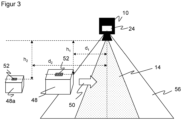
- the object 48 is detected upon entering the distance measurement field of view 56 .
- the recording should preferably be triggered when it is in the middle of the detection area 14 .
- the path d 1 still depends on the distance h 1 , since objects 48 of different heights are detected for the first time in different positions.
- Comparable considerations can be made for the other objects, only one other object 48a of a height h 2 with a path d 2 still to be covered being shown as a representative.
- the control and evaluation unit 38 thus has the figure 3 removable relevant geometric information and trigger times.
- the aperture of the adjustable aperture 17 can thus be set in good time for recording each object 48, 48a in accordance with the respective distance value of the distance sensor 24 or the height h 1 , h 2 that can be calculated therefrom.
- An object 48a that is further away from the camera 10 and thus has a lower height h 1 ⁇ h 2 is perceived as darker because the amplitude of the signal decreases with the square of the distance.
- the code 52 appears on an object 48a with lower height h 2 smaller, so better resolution is needed.
- a closed aperture increases the depth of field and reduces the resolution. Which reduction and which signal-to-noise ratio can still be tolerated depends on the specific application. This becomes clear using the example of code reading: In the end, what matters is not whether images meet physical quality criteria, but whether the code can be read.
- the appropriate aperture setting for a distance value is therefore preferably based on whether it is guaranteed that a code will be readable. This can vary depending on the code type, module size, exposure and decoder used, so that it can make sense to know several aperture settings for the respective distance values depending on these parameters and to use them during operation depending on the situation.
- a basis for adjusting the aperture can be given as follows.
- Lambda is the wavelength here, with polychromatic LEDs, for example, the mean value can be used.
- N is the f-number and is inversely proportional to the diameter of the aperture.
- the factor 1.22 corresponds to a zero position of the Bessel function and can alternatively be chosen differently.
- DOF alpha ⁇ 2 right 2 ⁇ N ⁇ C f 2 .
- alpha is an empirical correction factor
- C is the so-called "circle of confusion", which is related to the resolution limit and graphically represents the smallest unit that is still to be resolved.
- the aperture setting results If the object is small, the aperture should be opened. Thus, the depth of field DOF becomes small. A static focus position of the receiving optics 16 should therefore be designed for large distances or small objects, so that the small module size can be read in a code reading application. With smaller distances or larger objects and the same focus position, the aperture is closed until the depth of field DOF is sufficient to be able to read the code. Thanks to the smaller distance value, the module size in pixels is larger, so that the more closed aperture is tolerated.
- This aperture adjustment is also an advantage because it partially compensates for the brightness dynamics.
- the number of photons reaching the camera 10 depends on the diameter d of the aperture: signal ⁇ 1 / i.e 2 .
- an aperture (distance) function can be found, with which the control and evaluation unit 38 finds the appropriate setting for the adjustable aperture 17 for the distance value measured in each case.
- the image is sharp due to the depth of field, which is extended if necessary by the aperture, and provides sufficient signal so that the decoder can read the code (good read).
- a starting point can first be found by positioning the lowest expected object with the correspondingly smallest module size in the detection area 14 . In the case of a fixed focus system, this preferably corresponds to its focus position. The aperture is opened wide enough that the code can still be read, and this corresponds to the value to be set for the aperture at this distance. For higher objects, the aperture is closed further to compensate for the blur. It is conceivable to calibrate at least one other value of the aperture (distance) function using an object of the corresponding height. Interpolation or extrapolation can be carried out for other distance values or heights from the aperture settings that have been taught in.
Landscapes
- Engineering & Computer Science (AREA)
- Physics & Mathematics (AREA)
- General Physics & Mathematics (AREA)
- Multimedia (AREA)
- Signal Processing (AREA)
- Theoretical Computer Science (AREA)
- Computer Vision & Pattern Recognition (AREA)
- Computer Networks & Wireless Communication (AREA)
- Electromagnetism (AREA)
- Radar, Positioning & Navigation (AREA)
- Remote Sensing (AREA)
- Computing Systems (AREA)
- Artificial Intelligence (AREA)
- Studio Devices (AREA)
- Length Measuring Devices By Optical Means (AREA)
- Measurement Of Optical Distance (AREA)
- Exposure Control For Cameras (AREA)
- Automatic Focus Adjustment (AREA)
Claims (14)
- Caméra (10) pour la détection d'objets (48) déplacés à travers une zone de détection (14), la caméra (10) comprenant un capteur d'image (18) pour l'enregistrement de données d'image, une optique de réception (16) avec un diaphragme réglable (17), ainsi qu'une unité de commande et d'évaluation (38) pour lire les données d'image et pour régler le diaphragme (17),
caractérisée en ce que
l'optique de réception (16) comprend une position focale fixe, en ce que la caméra (10) comprend un capteur de distance (24) pour mesurer une valeur de distance à un objet (48), et en ce que l'unité de commande et d'évaluation (38) est configurée pour régler le diaphragme (17) par objet (48) en fonction d'une valeur de distance mesurée pour l'objet (48), de telle sorte que l'objet (48) soit enregistré dans une zone de profondeur de champ dans laquelle les données d'image enregistrées atteignent une netteté d'image requise. - Caméra (10) selon la revendication 1,
dans laquelle la zone de profondeur de champ est déterminée à partir d'exigences spécifiques à l'application. - Caméra (10) selon la revendication 1 ou 2,
dans laquelle l'unité de commande et d'évaluation (38) est configurée pour lire le contenu d'un code (52) sur l'objet (48) à l'aide des données d'image. - Caméra (10) selon la revendication 3,
dans laquelle l'objet (48) est enregistré dans la zone de profondeur de champ lorsqu'un code peut être lu à partir des données d'image enregistrées. - Caméra (10) selon la revendication 3 ou 4,
dans laquelle la zone de profondeur de champ requise dépend d'un type de code, d'une taille de module, d'une exposition et/ou d'un procédé de décodage. - Caméra (10) selon l'une des revendications précédentes,
dans laquelle le capteur de distance (24) est intégré à la caméra (10) et/ou est configuré comme un capteur de distance optoélectronique (24) selon le principe du procédé du temps de vol de la lumière. - Caméra (10) selon l'une des revendications précédentes,
dans laquelle l'unité de commande et d'évaluation (38) est configurée pour régler le diaphragme (17) pour un objet (48) à l'aide d'une fonction de l'ouverture requise en fonction de la distance d'un objet (48). - Caméra (10) selon l'une des revendications précédentes,
dans laquelle l'unité de commande et d'évaluation (38) est configurée pour un processus d'apprentissage dans lequel un objet (48) est placé à une distance, des données d'image sont enregistrées, une netteté d'image est vérifiée et le diaphragme (17) est ajusté jusqu'à ce qu'un réglage d'ouverture approprié soit trouvé pour cette distance. - Caméra (10) selon l'une des revendications précédentes,
dans laquelle l'optique de réception (16) comprend la position focale fixe pour une distance maximale de l'objet. - Caméra (10) selon l'une des revendications précédentes,
dans laquelle l'unité de commande et d'évaluation (38) est configurée pour régler le diaphragme (17) sur une ouverture maximale pour un objet (48) à une distance correspondant à la position focale et pour fermer de plus en plus le diaphragme (17) pour des distances différentes, en particulier des distances plus petites. - Caméra (10) selon l'une des revendications précédentes,
dans laquelle l'unité de commande et d'évaluation (38) est configurée pour régler le diaphragme (17) en fonction d'une luminosité, en particulier des données d'image. - Caméra (10) selon l'une des revendications précédentes,
dans laquelle le diaphragme (17) est intégré dans l'optique de réception (16) ou est monté sur l'optique de réception (16). - Caméra (10) selon l'une des revendications précédentes,
qui est montée de manière stationnaire sur un dispositif de transport (46) qui guide les objets (48) à détecter dans une direction de transport (50) à travers la zone de détection (14). - Procédé de détection d'objets (48) déplacés à travers une zone de détection (14), dans lequel des données d'image sont enregistrées avec un capteur d'image (18) à travers une optique de réception (16) avec un diaphragme réglable (17), et les données d'image sont lues,
caractérisé en ce que l'optique de réception (16) comprend une position focale fixe, en ce qu'une valeur de distance à un objet (48) est mesurée avec un capteur de distance (24), et en ce que le diaphragme (17) par objet (48) est réglé en fonction d'une valeur de distance mesurée pour l'objet (48) de telle sorte que l'objet (48) soit enregistré dans une zone de profondeur de champ dans laquelle les données d'image enregistrées atteignent une netteté d'image requise.
Applications Claiming Priority (1)
| Application Number | Priority Date | Filing Date | Title |
|---|---|---|---|
| DE102021114556.2A DE102021114556A1 (de) | 2021-06-07 | 2021-06-07 | Kamera und Verfahren zur Erfassung von durch einen Erfassungsbereich bewegten Objekten |
Publications (3)
| Publication Number | Publication Date |
|---|---|
| EP4102293A1 EP4102293A1 (fr) | 2022-12-14 |
| EP4102293B1 true EP4102293B1 (fr) | 2023-08-09 |
| EP4102293C0 EP4102293C0 (fr) | 2023-08-09 |
Family
ID=81842038
Family Applications (1)
| Application Number | Title | Priority Date | Filing Date |
|---|---|---|---|
| EP22171385.2A Active EP4102293B1 (fr) | 2021-06-07 | 2022-05-03 | Caméra et procédé de détection des objets se déplaçant dans une zone de détection |
Country Status (5)
| Country | Link |
|---|---|
| US (1) | US11743602B2 (fr) |
| EP (1) | EP4102293B1 (fr) |
| JP (1) | JP2022187471A (fr) |
| CN (1) | CN115508845A (fr) |
| DE (1) | DE102021114556A1 (fr) |
Family Cites Families (21)
| Publication number | Priority date | Publication date | Assignee | Title |
|---|---|---|---|---|
| DE19710724C2 (de) | 1997-03-14 | 2002-09-26 | Sick Ag | Optoelektronischer Sensor |
| US7025271B2 (en) | 2002-12-18 | 2006-04-11 | Symbol Technologies, Inc. | Imaging optical code reader having selectable depths of field |
| JP4916355B2 (ja) * | 2007-03-20 | 2012-04-11 | 三洋電機株式会社 | 絞り制御装置及び画像処理装置 |
| JP2008312144A (ja) | 2007-06-18 | 2008-12-25 | Canon Inc | 撮像装置及び撮像装置の制御方法 |
| JP2010262173A (ja) * | 2009-05-08 | 2010-11-18 | Sony Corp | 撮像装置および撮影レンズユニット |
| US20100310246A1 (en) | 2009-06-04 | 2010-12-09 | Digital Imaging Systems Gmbh | Method for using a variable aperture to tune image quality parameters in a camera system |
| DE202009017346U1 (de) | 2009-12-21 | 2011-05-12 | Sick Ag | Optikvorrichtung für einen optoelektronischen Sensor |
| JP5479123B2 (ja) * | 2010-01-19 | 2014-04-23 | 京セラ株式会社 | 撮像装置および電子機器 |
| US8395682B2 (en) | 2011-03-08 | 2013-03-12 | Neal Solomon | System and methods for image depth-of-field modulation |
| EP2677363A1 (fr) * | 2012-06-20 | 2013-12-25 | bioMérieux | Dispositif optique comprenant une caméra, un diaphragme et moyens d'éclairage |
| WO2014023332A1 (fr) * | 2012-08-07 | 2014-02-13 | Carl Zeiss Industrielle Messtechnik Gmbh | Appareil de mesure des coordonnées pour la détermination de coordonnées spatiales sur un objet de mesure |
| DE102013224704A1 (de) * | 2013-12-03 | 2015-06-03 | Robert Bosch Gmbh | Verfahren zur automatischen Fokussierung einer Kamera |
| JP6739979B2 (ja) * | 2016-04-21 | 2020-08-12 | オリンパス株式会社 | 光学機器および絞り制御方法 |
| JP6753744B2 (ja) * | 2016-09-09 | 2020-09-09 | ヤマハ発動機株式会社 | 基板作業装置 |
| DE102016122335A1 (de) * | 2016-11-21 | 2018-05-24 | Pepperl + Fuchs Gmbh | Optischer Sensor zum Nachweis von Objekten in einem Überwachungsbereich und Verfahren zum Betreiben eines optischen Sensors |
| JP6928458B2 (ja) * | 2017-02-23 | 2021-09-01 | 株式会社キーエンス | 光学的情報読取装置 |
| DE102018105301B4 (de) | 2018-03-08 | 2021-03-18 | Sick Ag | Kamera und Verfahren zur Erfassung von Bilddaten |
| EP3812953B1 (fr) * | 2019-10-22 | 2021-09-29 | Sick Ag | Lecteur de codes et procédé de lecture des codes optiques |
| DE102020109929B3 (de) | 2020-04-09 | 2021-01-14 | Sick Ag | Erfassung von Bilddaten eines bewegten Objekts |
| DE102020109928B3 (de) | 2020-04-09 | 2020-12-31 | Sick Ag | Kamera und Verfahren zur Erfassung von Bilddaten |
| CN111766047B (zh) * | 2020-06-03 | 2022-12-09 | 杭州三泰检测技术有限公司 | 一种模拟人眼的激光显示视觉散斑检测装置 |
-
2021
- 2021-06-07 DE DE102021114556.2A patent/DE102021114556A1/de not_active Withdrawn
-
2022
- 2022-05-03 EP EP22171385.2A patent/EP4102293B1/fr active Active
- 2022-05-17 JP JP2022080638A patent/JP2022187471A/ja active Pending
- 2022-06-06 US US17/833,281 patent/US11743602B2/en active Active
- 2022-06-07 CN CN202210639691.4A patent/CN115508845A/zh active Pending
Also Published As
| Publication number | Publication date |
|---|---|
| DE102021114556A1 (de) | 2022-12-08 |
| EP4102293A1 (fr) | 2022-12-14 |
| CN115508845A (zh) | 2022-12-23 |
| JP2022187471A (ja) | 2022-12-19 |
| US20220394185A1 (en) | 2022-12-08 |
| EP4102293C0 (fr) | 2023-08-09 |
| US11743602B2 (en) | 2023-08-29 |
Similar Documents
| Publication | Publication Date | Title |
|---|---|---|
| EP3537339A2 (fr) | Caméra et procédé de détection des données d'image | |
| EP3893051B1 (fr) | Acquisition de données d'image d'un objet mobile | |
| EP3892955B1 (fr) | Caméra et procédé de détection des données d'image | |
| EP2546776B1 (fr) | Lecteur de code basé sur un appareil de prise de vue et son procédé de fabrication ajustée | |
| EP3812953B1 (fr) | Lecteur de codes et procédé de lecture des codes optiques | |
| EP3663963B1 (fr) | Lecture de codes optiques | |
| DE102014104026B3 (de) | Optoelektronische Vorrichtung und Verfahren zum Aufnehmen eines Bildes | |
| EP4075394A1 (fr) | Détection d'un flux mobile d'objets | |
| DE102020112430B4 (de) | Kamera und Verfahren zur Erfassung von Objekten | |
| DE112019001292T5 (de) | Lichtdetektionssvorrichtung, Lichtdetektionssverfahren und Lidarvorrichtung | |
| EP3528042A1 (fr) | Caméra et procédé de détection des données d'image | |
| EP3910547B1 (fr) | Détection des objets mobiles | |
| EP3591567B1 (fr) | Capteur optoélectronique et procédé de détection optique répétitive d'objets à distance de l'objet différente | |
| EP4102293B1 (fr) | Caméra et procédé de détection des objets se déplaçant dans une zone de détection | |
| DE202006020599U1 (de) | Optische Erfassung von bewegten Objekten und Vorrichtung | |
| DE102017119282A1 (de) | Optische Abbildungsvorrichtungen und -verfahren | |
| DE69921230T2 (de) | Optischer Symbolenabtaster | |
| DE202021103066U1 (de) | Kamera zur Erfassung von durch einen Erfassungsbereich bewegten Objekten | |
| EP4047507B1 (fr) | Détection d'un code optique | |
| EP3724601B1 (fr) | Détermination de la distance basée sur différentes profondeurs de champ avec différents réglages de mise au point d'une lentille d'objectif | |
| EP4270917B1 (fr) | Caméra et procédé de capture d'un objet | |
| EP4358530B1 (fr) | Détection d'objets d'un flux d'objets en mouvement | |
| DE102019128710B4 (de) | Kamera und Verfahren zur Erfassung von Bilddaten aus einem Erfassungsbereich | |
| CH706625B1 (de) | Verfahren zur Erfassung von Codes mittels eines optischen Sensors | |
| DE202019105903U1 (de) | Beleuchtung eines Erfassungsbereichs zum Erfassen von Bilddaten |
Legal Events
| Date | Code | Title | Description |
|---|---|---|---|
| PUAI | Public reference made under article 153(3) epc to a published international application that has entered the european phase |
Free format text: ORIGINAL CODE: 0009012 |
|
| STAA | Information on the status of an ep patent application or granted ep patent |
Free format text: STATUS: THE APPLICATION HAS BEEN PUBLISHED |
|
| STAA | Information on the status of an ep patent application or granted ep patent |
Free format text: STATUS: REQUEST FOR EXAMINATION WAS MADE |
|
| AK | Designated contracting states |
Kind code of ref document: A1 Designated state(s): AL AT BE BG CH CY CZ DE DK EE ES FI FR GB GR HR HU IE IS IT LI LT LU LV MC MK MT NL NO PL PT RO RS SE SI SK SM TR |
|
| 17P | Request for examination filed |
Effective date: 20221130 |
|
| RBV | Designated contracting states (corrected) |
Designated state(s): AL AT BE BG CH CY CZ DE DK EE ES FI FR GB GR HR HU IE IS IT LI LT LU LV MC MK MT NL NO PL PT RO RS SE SI SK SM TR |
|
| GRAJ | Information related to disapproval of communication of intention to grant by the applicant or resumption of examination proceedings by the epo deleted |
Free format text: ORIGINAL CODE: EPIDOSDIGR1 |
|
| GRAP | Despatch of communication of intention to grant a patent |
Free format text: ORIGINAL CODE: EPIDOSNIGR1 |
|
| RIC1 | Information provided on ipc code assigned before grant |
Ipc: G06V 30/424 20220101ALI20230208BHEP Ipc: G06V 30/14 20220101ALI20230208BHEP Ipc: H04N 23/75 20230101ALI20230208BHEP Ipc: H04N 23/61 20230101ALI20230208BHEP Ipc: G03B 13/32 20060101ALI20230208BHEP Ipc: G03B 13/20 20060101ALI20230208BHEP Ipc: G03B 9/02 20060101ALI20230208BHEP Ipc: G03B 7/00 20060101AFI20230208BHEP |
|
| GRAP | Despatch of communication of intention to grant a patent |
Free format text: ORIGINAL CODE: EPIDOSNIGR1 |
|
| STAA | Information on the status of an ep patent application or granted ep patent |
Free format text: STATUS: GRANT OF PATENT IS INTENDED |
|
| INTG | Intention to grant announced |
Effective date: 20230404 |
|
| GRAS | Grant fee paid |
Free format text: ORIGINAL CODE: EPIDOSNIGR3 |
|
| GRAA | (expected) grant |
Free format text: ORIGINAL CODE: 0009210 |
|
| STAA | Information on the status of an ep patent application or granted ep patent |
Free format text: STATUS: THE PATENT HAS BEEN GRANTED |
|
| AK | Designated contracting states |
Kind code of ref document: B1 Designated state(s): AL AT BE BG CH CY CZ DE DK EE ES FI FR GB GR HR HU IE IS IT LI LT LU LV MC MK MT NL NO PL PT RO RS SE SI SK SM TR |
|
| REG | Reference to a national code |
Ref country code: GB Ref legal event code: FG4D Free format text: NOT ENGLISH |
|
| REG | Reference to a national code |
Ref country code: CH Ref legal event code: EP |
|
| REG | Reference to a national code |
Ref country code: IE Ref legal event code: FG4D Free format text: LANGUAGE OF EP DOCUMENT: GERMAN |
|
| REG | Reference to a national code |
Ref country code: DE Ref legal event code: R096 Ref document number: 502022000080 Country of ref document: DE |
|
| U01 | Request for unitary effect filed |
Effective date: 20230828 |
|
| U07 | Unitary effect registered |
Designated state(s): AT BE BG DE DK EE FI FR IT LT LU LV MT NL PT SE SI Effective date: 20230904 |
|
| PG25 | Lapsed in a contracting state [announced via postgrant information from national office to epo] |
Ref country code: GR Free format text: LAPSE BECAUSE OF FAILURE TO SUBMIT A TRANSLATION OF THE DESCRIPTION OR TO PAY THE FEE WITHIN THE PRESCRIBED TIME-LIMIT Effective date: 20231110 |
|
| PG25 | Lapsed in a contracting state [announced via postgrant information from national office to epo] |
Ref country code: IS Free format text: LAPSE BECAUSE OF FAILURE TO SUBMIT A TRANSLATION OF THE DESCRIPTION OR TO PAY THE FEE WITHIN THE PRESCRIBED TIME-LIMIT Effective date: 20231209 |
|
| PG25 | Lapsed in a contracting state [announced via postgrant information from national office to epo] |
Ref country code: RS Free format text: LAPSE BECAUSE OF FAILURE TO SUBMIT A TRANSLATION OF THE DESCRIPTION OR TO PAY THE FEE WITHIN THE PRESCRIBED TIME-LIMIT Effective date: 20230809 Ref country code: NO Free format text: LAPSE BECAUSE OF FAILURE TO SUBMIT A TRANSLATION OF THE DESCRIPTION OR TO PAY THE FEE WITHIN THE PRESCRIBED TIME-LIMIT Effective date: 20231109 Ref country code: IS Free format text: LAPSE BECAUSE OF FAILURE TO SUBMIT A TRANSLATION OF THE DESCRIPTION OR TO PAY THE FEE WITHIN THE PRESCRIBED TIME-LIMIT Effective date: 20231209 Ref country code: HR Free format text: LAPSE BECAUSE OF FAILURE TO SUBMIT A TRANSLATION OF THE DESCRIPTION OR TO PAY THE FEE WITHIN THE PRESCRIBED TIME-LIMIT Effective date: 20230809 Ref country code: GR Free format text: LAPSE BECAUSE OF FAILURE TO SUBMIT A TRANSLATION OF THE DESCRIPTION OR TO PAY THE FEE WITHIN THE PRESCRIBED TIME-LIMIT Effective date: 20231110 |
|
| PG25 | Lapsed in a contracting state [announced via postgrant information from national office to epo] |
Ref country code: PL Free format text: LAPSE BECAUSE OF FAILURE TO SUBMIT A TRANSLATION OF THE DESCRIPTION OR TO PAY THE FEE WITHIN THE PRESCRIBED TIME-LIMIT Effective date: 20230809 |
|
| PG25 | Lapsed in a contracting state [announced via postgrant information from national office to epo] |
Ref country code: ES Free format text: LAPSE BECAUSE OF FAILURE TO SUBMIT A TRANSLATION OF THE DESCRIPTION OR TO PAY THE FEE WITHIN THE PRESCRIBED TIME-LIMIT Effective date: 20230809 |
|
| PG25 | Lapsed in a contracting state [announced via postgrant information from national office to epo] |
Ref country code: SM Free format text: LAPSE BECAUSE OF FAILURE TO SUBMIT A TRANSLATION OF THE DESCRIPTION OR TO PAY THE FEE WITHIN THE PRESCRIBED TIME-LIMIT Effective date: 20230809 Ref country code: RO Free format text: LAPSE BECAUSE OF FAILURE TO SUBMIT A TRANSLATION OF THE DESCRIPTION OR TO PAY THE FEE WITHIN THE PRESCRIBED TIME-LIMIT Effective date: 20230809 Ref country code: ES Free format text: LAPSE BECAUSE OF FAILURE TO SUBMIT A TRANSLATION OF THE DESCRIPTION OR TO PAY THE FEE WITHIN THE PRESCRIBED TIME-LIMIT Effective date: 20230809 Ref country code: CZ Free format text: LAPSE BECAUSE OF FAILURE TO SUBMIT A TRANSLATION OF THE DESCRIPTION OR TO PAY THE FEE WITHIN THE PRESCRIBED TIME-LIMIT Effective date: 20230809 Ref country code: SK Free format text: LAPSE BECAUSE OF FAILURE TO SUBMIT A TRANSLATION OF THE DESCRIPTION OR TO PAY THE FEE WITHIN THE PRESCRIBED TIME-LIMIT Effective date: 20230809 |
|
| REG | Reference to a national code |
Ref country code: DE Ref legal event code: R097 Ref document number: 502022000080 Country of ref document: DE |
|
| PLBE | No opposition filed within time limit |
Free format text: ORIGINAL CODE: 0009261 |
|
| STAA | Information on the status of an ep patent application or granted ep patent |
Free format text: STATUS: NO OPPOSITION FILED WITHIN TIME LIMIT |
|
| U20 | Renewal fee for the european patent with unitary effect paid |
Year of fee payment: 3 Effective date: 20240516 |
|
| 26N | No opposition filed |
Effective date: 20240513 |
|
| PG25 | Lapsed in a contracting state [announced via postgrant information from national office to epo] |
Ref country code: MC Free format text: LAPSE BECAUSE OF FAILURE TO SUBMIT A TRANSLATION OF THE DESCRIPTION OR TO PAY THE FEE WITHIN THE PRESCRIBED TIME-LIMIT Effective date: 20230809 |
|
| PG25 | Lapsed in a contracting state [announced via postgrant information from national office to epo] |
Ref country code: MC Free format text: LAPSE BECAUSE OF FAILURE TO SUBMIT A TRANSLATION OF THE DESCRIPTION OR TO PAY THE FEE WITHIN THE PRESCRIBED TIME-LIMIT Effective date: 20230809 |
|
| PG25 | Lapsed in a contracting state [announced via postgrant information from national office to epo] |
Ref country code: IE Free format text: LAPSE BECAUSE OF NON-PAYMENT OF DUE FEES Effective date: 20240503 |
|
| U20 | Renewal fee for the european patent with unitary effect paid |
Year of fee payment: 4 Effective date: 20250516 |
|
| PGFP | Annual fee paid to national office [announced via postgrant information from national office to epo] |
Ref country code: CH Payment date: 20250601 Year of fee payment: 4 |
|
| PG25 | Lapsed in a contracting state [announced via postgrant information from national office to epo] |
Ref country code: CY Free format text: LAPSE BECAUSE OF FAILURE TO SUBMIT A TRANSLATION OF THE DESCRIPTION OR TO PAY THE FEE WITHIN THE PRESCRIBED TIME-LIMIT; INVALID AB INITIO Effective date: 20220503 |
|
| PG25 | Lapsed in a contracting state [announced via postgrant information from national office to epo] |
Ref country code: HU Free format text: LAPSE BECAUSE OF FAILURE TO SUBMIT A TRANSLATION OF THE DESCRIPTION OR TO PAY THE FEE WITHIN THE PRESCRIBED TIME-LIMIT; INVALID AB INITIO Effective date: 20220503 |
|
| PGFP | Annual fee paid to national office [announced via postgrant information from national office to epo] |
Ref country code: GB Payment date: 20260324 Year of fee payment: 5 |