EP4102916A1 - Procédé de déclenchement de phr prenant en charge une partie dormante de bande passante dans un système de communication mobile de prochaine génération, et procédé et dispositif de configuration de phr - Google Patents
Procédé de déclenchement de phr prenant en charge une partie dormante de bande passante dans un système de communication mobile de prochaine génération, et procédé et dispositif de configuration de phr Download PDFInfo
- Publication number
- EP4102916A1 EP4102916A1 EP21792887.8A EP21792887A EP4102916A1 EP 4102916 A1 EP4102916 A1 EP 4102916A1 EP 21792887 A EP21792887 A EP 21792887A EP 4102916 A1 EP4102916 A1 EP 4102916A1
- Authority
- EP
- European Patent Office
- Prior art keywords
- bwp
- dormant
- scell
- activated
- downlink
- Prior art date
- Legal status (The legal status is an assumption and is not a legal conclusion. Google has not performed a legal analysis and makes no representation as to the accuracy of the status listed.)
- Pending
Links
Images










Classifications
-
- H—ELECTRICITY
- H04—ELECTRIC COMMUNICATION TECHNIQUE
- H04W—WIRELESS COMMUNICATION NETWORKS
- H04W72/00—Local resource management
- H04W72/04—Wireless resource allocation
- H04W72/044—Wireless resource allocation based on the type of the allocated resource
- H04W72/0453—Resources in frequency domain, e.g. a carrier in FDMA
-
- H—ELECTRICITY
- H04—ELECTRIC COMMUNICATION TECHNIQUE
- H04L—TRANSMISSION OF DIGITAL INFORMATION, e.g. TELEGRAPHIC COMMUNICATION
- H04L5/00—Arrangements affording multiple use of the transmission path
- H04L5/0001—Arrangements for dividing the transmission path
- H04L5/0003—Two-dimensional division
- H04L5/0005—Time-frequency
- H04L5/0007—Time-frequency the frequencies being orthogonal, e.g. OFDM(A) or DMT
- H04L5/001—Time-frequency the frequencies being orthogonal, e.g. OFDM(A) or DMT the frequencies being arranged in component carriers
-
- H—ELECTRICITY
- H04—ELECTRIC COMMUNICATION TECHNIQUE
- H04L—TRANSMISSION OF DIGITAL INFORMATION, e.g. TELEGRAPHIC COMMUNICATION
- H04L5/00—Arrangements affording multiple use of the transmission path
- H04L5/0091—Signalling for the administration of the divided path, e.g. signalling of configuration information
- H04L5/0096—Indication of changes in allocation
- H04L5/0098—Signalling of the activation or deactivation of component carriers, subcarriers or frequency bands
-
- H—ELECTRICITY
- H04—ELECTRIC COMMUNICATION TECHNIQUE
- H04W—WIRELESS COMMUNICATION NETWORKS
- H04W24/00—Supervisory, monitoring or testing arrangements
- H04W24/10—Scheduling measurement reports ; Arrangements for measurement reports
-
- H—ELECTRICITY
- H04—ELECTRIC COMMUNICATION TECHNIQUE
- H04W—WIRELESS COMMUNICATION NETWORKS
- H04W52/00—Power management, e.g. Transmission Power Control [TPC] or power classes
- H04W52/02—Power saving arrangements
- H04W52/0209—Power saving arrangements in terminal devices
- H04W52/0212—Power saving arrangements in terminal devices managed by the network, e.g. network or access point is leader and terminal is follower
- H04W52/0216—Power saving arrangements in terminal devices managed by the network, e.g. network or access point is leader and terminal is follower using a pre-established activity schedule, e.g. traffic indication frame
-
- H—ELECTRICITY
- H04—ELECTRIC COMMUNICATION TECHNIQUE
- H04W—WIRELESS COMMUNICATION NETWORKS
- H04W52/00—Power management, e.g. Transmission Power Control [TPC] or power classes
- H04W52/04—Transmission power control [TPC]
- H04W52/30—Transmission power control [TPC] using constraints in the total amount of available transmission power
- H04W52/36—Transmission power control [TPC] using constraints in the total amount of available transmission power with a discrete range or set of values, e.g. step size, ramping or offsets
- H04W52/365—Power headroom reporting
-
- H—ELECTRICITY
- H04—ELECTRIC COMMUNICATION TECHNIQUE
- H04W—WIRELESS COMMUNICATION NETWORKS
- H04W72/00—Local resource management
- H04W72/20—Control channels or signalling for resource management
- H04W72/23—Control channels or signalling for resource management in the downlink direction of a wireless link, i.e. towards a terminal
- H04W72/231—Control channels or signalling for resource management in the downlink direction of a wireless link, i.e. towards a terminal the control data signalling from the layers above the physical layer, e.g. RRC or MAC-CE signalling
-
- H—ELECTRICITY
- H04—ELECTRIC COMMUNICATION TECHNIQUE
- H04W—WIRELESS COMMUNICATION NETWORKS
- H04W52/00—Power management, e.g. Transmission Power Control [TPC] or power classes
- H04W52/04—Transmission power control [TPC]
- H04W52/18—TPC being performed according to specific parameters
- H04W52/24—TPC being performed according to specific parameters using SIR [Signal to Interference Ratio] or other wireless path parameters
- H04W52/242—TPC being performed according to specific parameters using SIR [Signal to Interference Ratio] or other wireless path parameters taking into account path loss
-
- H—ELECTRICITY
- H04—ELECTRIC COMMUNICATION TECHNIQUE
- H04W—WIRELESS COMMUNICATION NETWORKS
- H04W76/00—Connection management
- H04W76/10—Connection setup
- H04W76/15—Setup of multiple wireless link connections
-
- Y—GENERAL TAGGING OF NEW TECHNOLOGICAL DEVELOPMENTS; GENERAL TAGGING OF CROSS-SECTIONAL TECHNOLOGIES SPANNING OVER SEVERAL SECTIONS OF THE IPC; TECHNICAL SUBJECTS COVERED BY FORMER USPC CROSS-REFERENCE ART COLLECTIONS [XRACs] AND DIGESTS
- Y02—TECHNOLOGIES OR APPLICATIONS FOR MITIGATION OR ADAPTATION AGAINST CLIMATE CHANGE
- Y02D—CLIMATE CHANGE MITIGATION TECHNOLOGIES IN INFORMATION AND COMMUNICATION TECHNOLOGIES [ICT], I.E. INFORMATION AND COMMUNICATION TECHNOLOGIES AIMING AT THE REDUCTION OF THEIR OWN ENERGY USE
- Y02D30/00—Reducing energy consumption in communication networks
- Y02D30/70—Reducing energy consumption in communication networks in wireless communication networks
Definitions
- the disclosure relates to a method and an apparatus for efficiently managing a dormant bandwidth part in a next-generation mobile communication system.
- the 5G or pre-5G communication system is also called a "beyond 4G Network" communication system or a "post LTE” system.
- the 5G communication system is considered to be implemented in ultrahigh frequency (mmWave) bands (e.g., 60GHz bands) so as to accomplish higher data rates.
- mmWave ultrahigh frequency
- FD-MIMO full dimensional MIMO
- array antenna analog beam forming, large scale antenna techniques are discussed in 5G communication systems.
- RANs cloud radio access networks
- D2D device-to-device
- SWSC sliding window superposition coding
- ACM advanced coding modulation
- FBMC filter bank multi carrier
- NOMA non-orthogonal multiple access
- SCMA sparse code multiple access
- the Internet which is a human centered connectivity network where humans generate and consume information
- IoT Internet of things
- IoE Internet of everything
- sensing technology “wired/wireless communication and network infrastructure”, “service interface technology”, and “security technology”
- M2M machine-to-machine
- MTC machine type communication
- IoT Internet technology
- IoT may be applied to a variety of fields including smart home, smart building, smart city, smart car or connected cars, smart grid, health care, smart appliances and advanced medical services through convergence and combination between existing information technology (IT) and various industrial applications.
- technologies such as a sensor network, machine type communication (MTC), and machine-to-machine (M2M) communication may be implemented by beamforming, MIMO, and array antennas.
- MTC machine type communication
- M2M machine-to-machine
- Application of a cloud radio access network (cloud RAN) as the above-described big data processing technology may also be considered an example of convergence of the 5G technology with the IoT technology.
- a carrier aggregation technology is used in a next-generation mobile communication system in order to provide a service having a high data transmission rate and low transmission latency to a UE.
- a method of preventing processing latency that may be generated when carrier aggregation is configured and activated in a UE having a connection with a network or when carrier aggregation is deactivated after being used is needed.
- carrier aggregation may be used to provide a service having a high data transmission rate and low transmission latency to a UE.
- a method of preventing processing latency that may be generated when carrier aggregation is configured in a UE having a connection with a network and is activated or when carrier aggregation is deactivated after being used is needed.
- the UE maintains a plurality of cells in an activated state in order to use the carrier aggregation, the UE is required to monitor a PDCCH for each cell, so that battery consumption of the UE may increase.
- the plurality of cells remain in a deactivated state in order to reduce battery consumption of the UE, data transmission/reception latency may occur due to latency generated when the plurality of cells are activated through the use of carrier aggregation.
- a method performed by a terminal in a wireless communication system includes receiving, from a base station, a message including information for configuring a plurality of serving cells for the terminal, identifying whether a predetermined event for triggering a power headroom report (PHR) is occured, in case that the predetermined event is occured, obtaining a power headroom (PH) value for an uplink carrier corresponding to an activated serving cell of the plurality of serving cells, and transmitting, to the base station, the PHR including the obtained PH value, wherein an activated downlink bandwidth part (BWP) of the activated serving cell is not a dormant BWP.
- PHR power headroom report
- a terminal in a wireless communication system includes a transceiver, and a controller configured to control the transceiver to receive, from a base station, a message including information for configuring a plurality of serving cells for the terminal, identify whether a predetermined event for triggering a power headroom report (PHR) is occured, in case that the predetermined event is occured, obtain a power headroom (PH) value for an uplink carrier corresponding to an activated serving cell of the plurality of serving cells, and control the transceiver to transmit, to the base station, the PHR including the obtained PH value, wherein an activated downlink bandwidth part (BWP) of the activated serving cell is not a dormant BWP.
- PHR power headroom report
- a method performed by a base station in a wireless communication system includes transmitting, to a terminal, a message including information for configuring a plurality of serving cells for the terminal and configuration information on a power headroom report (PHR), and receiving, from the terminal, the PHR including a power headroom (HR) value for an uplink carrier corresponding to an activated serving cell of the plurality of serving cells, based on the message, wherein an activated downlink bandwidth part (BWP) of the activated serving cell is not a dormant BWP.
- PHR power headroom report
- the disclosure proposes a new dormant mode to allow a UE in an RRC-connected mode having a connection with a network to rapidly activate and deactivate carrier aggregation in a next-generation mobile communication system.
- the disclosure proposes a method of operating a new dormant (or hibernation) mode in units of bandwidth parts (bandwidth part-levels) to rapidly activate the carrier aggregation and save a battery of the UE.
- each block of the flowchart illustrations, and combinations of blocks in the flowchart illustrations can be implemented by computer program instructions.
- These computer program instructions can be provided to a processor of a general-purpose computer, special purpose computer, or other programmable data processing apparatus to produce a machine, such that the instructions, which execute via the processor of the computer or other programmable data processing apparatus, create means for implementing the functions specified in the flowchart block or blocks.
- These computer program instructions may also be stored in a computer usable or computer-readable memory that can direct a computer or other programmable data processing apparatus to function in a particular manner, such that the instructions stored in the computer usable or computer-readable memory produce an article of manufacture including instruction means that implement the function specified in the flowchart block or blocks.
- the computer program instructions may also be loaded onto a computer or other programmable data processing apparatus to cause a series of operational steps to be performed on the computer or other programmable apparatus to produce a computer implemented process such that the instructions that execute on the computer or other programmable apparatus provide steps for implementing the functions specified in the flowchart block or blocks.
- each block of the flowchart illustrations may represent a module, segment, or portion of code, which includes one or more executable instructions for implementing the specified logical function(s). It should also be noted that in some alternative implementations, the functions noted in the blocks may occur out of the order. For example, two blocks shown in succession may in fact be executed substantially concurrently or the blocks may sometimes be executed in the reverse order, depending upon the functionality involved.
- the "unit” refers to a software element or a hardware element, such as a Field Programmable Gate Array (FPGA) or an Application Specific Integrated Circuit (ASIC), which performs a predetermined function.
- FPGA Field Programmable Gate Array
- ASIC Application Specific Integrated Circuit
- the "unit” does not always have a meaning limited to software or hardware.
- the “unit” may be constructed either to be stored in an addressable storage medium or to execute one or more processors. Therefore, the "unit” includes, for example, software elements, object-oriented software elements, class elements or task elements, processes, functions, properties, procedures, sub-routines, segments of a program code, drivers, firmware, micro-codes, circuits, data, database, data structures, tables, arrays, and parameters.
- the elements and functions provided by the "unit” may be either combined into a smaller number of elements, or a “unit”, or divided into a larger number of elements, or a “unit”. Moreover, the elements and “units” or may be implemented to reproduce one or more CPUs within a device or a security multimedia card.
- the operation principle of the disclosure will be described in detail with reference to the accompanying drawings.
- a detailed description of known functions or configurations incorporated herein will be omitted when it is determined that the description may make the subject matter of the disclosure unnecessarily unclear.
- the terms which will be described below are terms defined in consideration of the functions in the disclosure, and may be different according to users, intentions of the users, or customs. Therefore, the definitions of the terms should be made based on the contents throughout the specification.
- eNB 3rd generation partnership project long term evolution
- gNB 3rd generation partnership project long term evolution
- FIG. 1 illustrates a structure of an LTE system to which the present disclosure can be applied.
- a radio access network of the LTE system includes next-generation base stations (evolved node Bs) (hereinafter, referred to as ENBs, Node Bs, or base stations) 1a-05, 1a-10, 1a-15, and 1a-20, a mobility management entity (MME) 1a-25, and a serving gateway (S-GW) 1a-30.
- ENBs next-generation base stations
- MME mobility management entity
- S-GW serving gateway
- the ENBs 1a-05 to 1a-20 correspond to the existing node Bs of the UMTS system.
- the ENB is connected to the UE 1a-35 through a radio channel, and performs a more complicated role than that of the conventional node B.
- VoIP voice over IP
- an apparatus for collecting and scheduling status information on buffer statuses of UEs, available transmission power status, and channel statuses is required, and the ENBs 1a-05 to 1a-20 may serve as this apparatus.
- One ENB generally controls a plurality of cells.
- the LTE system uses an orthogonal frequency division multiplexing (OFDM) as a radio access technology in a bandwidth of 20 MHz. Further, an adaptive modulation and coding (AMC) scheme of determining a modulation scheme and a channel coding rate is applied depending on the channel status of the UE.
- the S-GW 1a-30 is a device for providing a data bearer, and generates or removes the data bearer under a control of the MME 1a-25.
- the MME is a device for performing not only a function of managing mobility of the UE but also various control functions and is connected to a plurality of eNBs.
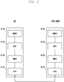
- FIG. 2 illustrates a radio protocol structure in the LTE system to which the present disclosure can be applied.
- the UE and the ENB include packet data convergence protocols (PDCPs) 1b-05 and 1b-40, radio link controls (RLCs) 1b-10 and 1b-35, and medium access controls (MACs) 1b-15 and 1b-30, respectively, in the wireless protocol of the LTE system.
- the packet data convergence protocols (PDCPs) 1b-05 and 1b-40 perform an operation of compressing/reconstructing an IP header. Main functions of the PDCP are described below.
- Radio link control (RLC) 1b-10 and 1b-35 reconfigure the PDCP packet data unit (PDU) to be the proper size and perform an automatic repeat request (ARQ) operation.
- RLC Radio link control
- PAR automatic repeat request
- the MACs 1b-15 and 1b-30 are connected with various RLC layer devices included in one UE, and perform an operation for multiplexing RLC PDUs to the MAC PDU and demultiplexing the RLC PDUs from the MAC PDU. Main functions of the MAC are described below.
- the PHY layers 1b-20 and 1b-25 perform an operation for channel-coding and modulating higher-layer data to generate an OFDM symbol and transmitting the OFDM symbol through a radio channel or demodulating and channel-decoding the OFDM symbol received through the radio channel and transmitting the demodulated and channel-decoded OFDM symbol to the higher layer.
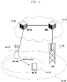
- FIG. 3 illustrates a structure of a next-generation mobile communication system to which the disclosure can be applied.
- a radio access network of a next-generation mobile communication system includes a next-generation base station 1c-10 (new-radio node B) (hereinafter, referred to as an NR gNB, or an NR base station) and a new-radio core network (NR CN) 1c-05.
- a user terminal 1c-15 (hereinafter, referred to as a new radio user equipment (NR UE) or a terminal) accesses an external network through the NR gNB 1c-10 and the NR CN 1c-05.
- NR UE new radio user equipment
- the NR gNB 1c-10 corresponds to an evolved Node B (eNB) of the conventional LTE system.
- the NR gNB may be connected to an NR UE 1c-15 through a radio channel and may provide better service than the conventional node B. Since all user traffic is served through a shared channel in the next-generation mobile communication system, a device for collecting and scheduling status information such as buffer statuses of UEs, available transmission power statuses, and channel statuses is required, and the NR NB 1c-10 serves as the device.
- One NR gNB generally controls a plurality of cells.
- the NR gNB may have a bandwidth wider than the conventional maximum bandwidth in order to implement super-high-speed data transmission compared to conventional LTE and may apply orthogonal frequency division multiplexing (OFDM) through radio access technology and further apply beamforming technology. Further, an adaptive modulation and coding (AMC) scheme of determining a modulation scheme and a channel coding rate is applied depending on the channel status of the UE.
- the NR CN 1c-05 performs a function of supporting mobility, configuring a bearer, and configuring a QoS.
- the NR CN is a device for performing a function of managing the mobility of the UE and various control functions, and is connected to a plurality of base stations. Further, the next-generation mobile communication system may interwork with the conventional LTE system, and the NR CN is connected to an MME 1c-25 through a network interface.
- the MME is connected to an eNB 1c-30, which is a conventional base station.
- FIG. 4 illustrates a wireless protocol structure of the next-generation mobile communication system to which the disclosure can be applied.
- the wireless protocol of the next-generation mobile communication system includes NR SDAPs Id-01 and Id-45, NR PDCPs Id-05 and Id-40, NR RLCs Id-10 and Id-35, and NR MACs Id-15 and Id-30 in the UE and the NR gNB.
- the main functions of the NR SDAPs Id-01 and Id-45 may include some of the following functions.
- the UE may receive a configuration as to whether to use a header of the SDAP layer device or a function of the SDAP layer device for each PDCP layer device, each bearer, or each logical channel through an RRC message. If the SDAP header is configured, a 1-bit indicator of NAS reflective QoS of the SDAP header and a 1 bit-indicator of AS reflective QoS may indicate that the UE updates or reconfigures information on mapping of QoS flow and a data bearer in uplink and downlink.
- the SDAP header may include QoS flow ID information indicating the QoS.
- the QoS information may be used as data-processing-priority or scheduling information to support a seamless service.
- the main functions of the NR PDCPs Id-05 and Id-40 may include some of the following functions.
- the reordering function of the NR PDCP device is a function of sequentially reordering PDCP PDUs received by a lower layer on the basis of a PDCP Sequence Number (SN), and may include a function of sequentially transferring the reordered data to a higher layer, a function of directly transmitting the recorded data regardless of the order, a function of recording PDCP PDUs lost due to the reordering, a function of reporting statuses of the lost PDCP PDUs to a transmitting side, and a function of making a request for retransmitting the lost PDCP PDUs.
- SN PDCP Sequence Number
- the main functions of the NR RLC Id-10 or Id-35 may include some of the following functions.
- the sequential delivery function (In-sequence delivery) of the NR RLC device is a function of sequentially transferring RLC SDUs received from a lower layer to a higher layer, and may include, when one original RLC SDU is divided into a plurality of RLC SDUs and then received, a function of reassembling and transmitting the RLC SDUs, a function of reordering the received RLC PDUs on the basis of an RLC Sequence Number (SN) or a PDCP SN, a function of recording PDCP PDUs lost due to the reordering, a function of reporting statuses of the lost PDCP PDUs to a transmitting side, a function of making a request for retransmitting the lost PDCP PDUs, a function of, if there is a lost RLC SDU, sequentially transferring only RLC SDUs preceding the lost RLC SDU to the higher layer, a function of, if a predetermined timer expires even though there
- the NR RLC device may process the RLC PDUs sequentially in a reception order thereof (according to an arrival order regardless of a serial number or a sequence number) and may transfer the RLC PDUs to the PDCP device regardless of the sequence thereof (out-of-sequence delivery).
- the NR RLC device may receive segments which are stored in the buffer or will be received in the future, reconfigure the segments to be one RLC PDU, process the RLC PDU, and then transmit the same to the PDCP device.
- the NR RLC layer may not include a concatenation function, and the function may be performed by the NR MAC layer, or may be replaced with a multiplexing function of the NR MAC layer.
- the non-sequential function (Out-of-sequence delivery) of the NR RLC device is a function of transferring RLC SDUs received from a lower layer directly to a higher layer regardless of the sequence of the RLC SDUs, and may include, when one original RLC SDU is divided into a plurality of RLC SDUs and then received, a function of reassembling and transmitting the RLC PDUs and a function of storing RLC SNs or PDCP SNs of the received RLC PDUs, reordering the RLC PDUs, and recording lost RLC PDUs.
- the NR MACs Id-15 and Id-30 may be connected to a plurality of NR RLC layer devices configured in one UE, and the main functions of the NR MACs may include some of the following functions.
- the NR PHY layers Id-20 and Id-25 perform an operation for channel-coding and modulating higher-layer data to generate an OFDM symbol and transmitting the OFDM symbol through a radio channel or demodulating and channel-decoding the OFDM symbol received through the radio channel and transmitting the demodulated and channel-decoded OFDM symbol to the higher layer.
- next-generation mobile communication system may introduce the concept of a bandwidth part (BWP), and thus a plurality of BWPs may be configured in one cell (SpCell or SCell) and data may be transmitted and received in one or a plurality of BWPs according to an indication of the NR gNB.
- BWP bandwidth part
- the disclosure proposes a state transition method or a bandwidth part switching method and a detailed operation considering a state of an SCell and a plurality of bandwidth parts configured in the SCell when a dormant bandwidth part proposed in the disclosure is introduced. Further, the disclosure proposes a method of managing a dormant mode in units of BWPs (BWP-levels) and transitioning a state or a BWP switching method, and also proposes a detailed operation in a BWP according to a state of each SCell or a state or a mode (active, inactive, or dormant) of each BWP.
- BWP-levels BWP-levels
- the disclosure configures a plurality of bandwidth parts for each downlink or uplink in one cell (SpCell, PCell, PScell, or SCell) and configures and operates active bandwidth part (active DL or UL BWP,) a dormant BWP (or dormant DL BWP), or an inactive bandwidth part (inactive or deactivated DL/UL BWP) through bandwidth part switching. That is, it is possible to increase a data transmission rate through a method similar to the carrier aggregation by transitioning a downlink or uplink BWP to an activated state for one cell and the UE does not monitor a PDCCH to save a battery by transitioning or switching the downlink BWP to a dormant BWP.
- the UE may measure a channel for the downlink BWP and report a channel measurement result, thereby supporting rapid activation of a cell or a BWP in the future.
- it is possible to save the battery life of the UE by transitioning the downlink (or uplink) BWP to a deactivated state in one cell.
- An indication of the state transition between BWPs for each cell or a BWP switching indication may be configured and indicated through a radio resource control (RRC) message, a medium access control (MAC) control element (CE), or downlink control information (DCI) of a physical downlink control channel (PDCCH).
- RRC radio resource control
- MAC medium access control
- DCI downlink control information
- the BWP may be used without distinction between the uplink and the downlink, and the meaning thereof may be each of an uplink BWP and a downlink BWP according to the context.
- the link may be used without any distinction between the uplink and the downlink, and the meaning thereof may indicate each of the uplink and the downlink.
- the disclosure configures and introduces a dormant BWP for the SCell of the UE performing carrier aggregation and not monitor a PDCCH in the dormant BWP so as to reduce battery consumption of the UE, and measures a channel (for example, measures or reports channel state information (CSI) or channel quality information (CQI)) or perform beam measurement, beam tracking, or beam operation, thereby performing switching or activation to a normal BWP and thus rapidly starting data transmission in the normal BWP in the case in which data transmission is needed.
- CSI channel state information
- CQI channel quality information
- the dormant BWP may not be configured or applied to the SpCell (the PCell of the MCG or the PCell of the SCG (or the PSCell)) in which a signal should be continuously monitored, feedback should be transmitted or received, or synchronization should be identified and maintained or the SCell in which a PUCCH is configured.
- the disclosure proposes various embodiments realized on the basis of PDCCH DCI, a MAC CE, or an RRC message in order to operate the dormant BWP proposed above for the SCell of the UE.
- the network or the base station may configure a SpCell (PCell and PSCell) and a plurality of SCells in the UE.
- the SpCell refers to a PCell when the UE communicates with one base station, and refers to a PCell of a master base station or a PSCell of a secondary base station when the UE communicates with two base stations (the master base station and the secondary base station).
- the PCell or the PSCell are primary cells used by each MAC layer device for communication between the UE and the base station, and correspond to cells for synchronizing timing, performing random access, transmitting HARQ ACK/NACK feedback through PUCCH transmission resources, and exchanging most control signals.
- a technology in which the base station operates a plurality of SCells as well as the SpCell to increase uplink or downlink transmission resources is referred to as a carrier aggregation technology.
- the UE may receive a configuration of a state or mode for each SCell or a BWP of the SCell through the RRC message and/or the MAC CE and/or the PDCCH DCI.
- the state or mode of the SCell may be configured as an active mode, activated state, a deactivated mode, or a deactivated state.
- the active mode or the activated state of the SCell may mean that the UE may exchange uplink or downlink data with the base station in a BWP other than an activated BWP of the SCell, an activated normal BWP, or an activated dormant BWP in the active mode or the activated SCell, monitors a PDCCH to identify an indication of the base station, measures a channel for a downlink of the SCell in the active mode or the activated state (or a BWP other than an activated BWP, an activated normal BWP, or an activated dormant BWP of the SCell), periodically reports measurement information, and periodically transmits a pilot signal (sounding reference signal (SRS)) to the base station so that the base station can measure an uplink channel.
- a pilot signal sounding reference signal (SRS)
- the deactivated mode or the deactivated state of the SCell may mean that the UE cannot exchange data with the base station, does not monitor a PDCCH to identify an indication of the base station, does not measure a channel, does not transmit a measurement report, and does not transmit a pilot signal since BWPs configured in the SCell is in the deactivated state, the configured BWPs are not activated, or there is no activated BWP among the configured BWPs.
- the base station in order to activate SCells in the deactivated mode, the base station first configures frequency measurement configuration information in the UE through an RRC message, and the UE measures a cell or a frequency on the basis of the frequency measurement configuration information.
- the base station may activate the deactivated SCells on the basis of frequency/channel measurement information after receiving the cell or frequency measurement report of the UE. Therefore, the base station activates the carrier aggregation technology for the UE and generates many delays to start data transmission or reception.
- the disclosure proposes a dormant mode or a dormant state for a BWP of each activated SCell (or active SCell) or proposes a configuration or introduction of a dormant bandwidth part (BWP) for each activated SCell in order to reduce a battery of the UE and rapidly start data transmission or reception.
- BWP dormant bandwidth part
- the UE In a BWP in a dormant mode of the activated SCell or a dormant BWP (dormant BWP in the activated SCell) or when the dormant BWP is activated, the UE cannot exchange data with the base station, does not monitor a PDCCH to identify an indication from the base station, or does not transmit a pilot signal but measures a channel, and transmits a report on the measurement result of the measured frequency/cell/channel according to a configuration of the base station periodically or when an event is generated.
- the UE since the UE does not monitor the PDCCH and does not transmit the pilot signal in the dormant BWP in the activated SCell, the UE may save a battery life compared to a normal BWP (or a BWP which is not the dormant BWP) of the activated SCell or compared to the case in which a normal BWP (or a BWP which is not the dormant BWP) of the activated SCell is activated, and does not transmit the pilot signal may reduce a transmission delay by rapidly activating the normal BWP of the activated SCell based on the measurement report or the measurement report of the dormant BWP of the activated SCell to promptly use the carrier aggregation since the channel measurement report is transmitted unlike the case in which the SCell is deactivated.
- the active mode or the activated state of the SCell may mean that the UE may exchange uplink or downlink data with the base station in a BWP other than an activated BWP of the SCell, an activated normal BWP, or an activated dormant BWP in the active mode or the activated SCell, monitors a PDCCH to identify an indication of the base station, measures a channel for a downlink of the SCell in the active mode or the activated state (or a BWP other than an activated BWP, an activated normal BWP, or an activated dormant BWP of the SCell), periodically reports measurement information, and periodically transmits a pilot signal (sounding reference signal (SRS)) to the base station so that the base station can measure an uplink channel.
- a pilot signal sounding reference signal (SRS)
- the active mode or the activated state of the SCell may mean that the UE cannot exchange uplink or downlink data with the base station in an activated dormant BWP of the SCell, does not monitor a PDCCH to identify an indication of the base station but measures a channel for the downlink of the activated dormant BWP of the SCell in the active mode or the activated state, and periodically reports measurement information to the base station in the active mode or the activated SCell.
- the dormant BWP may indicate a state of the BWP or may be used as a name of the logical concept indicating a specific BWP. Accordingly, the dormant BWP may be activated, deactivated, or switched. For example, an indication indicating switching of a second BWP activated in a first SCell to a dormant BWP, an indication indicating transition of the first SCell to a dormant state or a dormant mode, or an indication indicating activation of the dormant BWP of the first SCell may be interpreted as the same meaning.
- the normal BWP may indicate a BWP other than a dormant BWP among a BWP configured in each SCell of the UE through an RRC message.
- the UE may exchange uplink or downlink data with the base station, monitors a PDCCH to identify an indication of the base station, measures a channel for the downlink, periodically reports measurement information to the base station, and periodically transmits a pilot signal (sounding reference signal (SRS)) to the base station to allow the base station to measure an uplink channel.
- the normal BWP may indicate a first active BWP, a default BWP, a first active BWP from dormant, or an initial active BWP from dormant.
- only one dormant BWP may be configured for the downlink.
- one dormant BWP may be configured for the uplink or the downlink.
- FIG. 5 illustrates a procedure of serving the UE through the efficient use of a very wide frequency bandwidth in the next-generation mobile communication system of the disclosure.
- FIG. 5 a method of providing a service to UEs having different capabilities (or categories) by efficiently using a significantly wide frequency bandwidth and saving a battery in the next-generation mobile communication system is described.
- One cell in which the NR gNB provides service may serve a very wide frequency BWP as indicated by reference numeral 1e-05.
- the wide frequency bandwidth may be divided into a plurality of BWPs to manage one cell.
- the UE of which power is initially turned on may search the entire frequency band provided by a service provider (PLMN) in units of predetermined resource blocks (for example, in units of 12 resource blocks (RBs)). That is, the UE may start discovering a primary synchronization sequence (PSS)/secondary synchronization sequence (SSS) in the entire system bandwidth in units of resource blocks as indicated by reference numeral 1e-10. If the UE searches for the PSS/SSS 1e-01 or 1e-02 in units of resource blocks and then detects the signals, the UE may read the signals, analyze (decode) the signals, and identify a boundary between a subframe and a radio transmission resource frame (radio frame). Accordingly, the UE may identify subframes in units of 1 ms and synchronize a downlink signal with the NR gNB.
- PLMN service provider
- the resource block (RB) is the size of a predetermined frequency resource and a predetermined time resource, and may be defined as a two-dimensional unit.
- the UE may identify information on a control resource set (CORESET) by checking a master system information block (MIB) or minimum system information (MSI) and identify initial access bandwidth part (BWP) information, as indicated by reference numerals 1e-15 and 1e-20.
- MIB master system information block
- MSI minimum system information
- BWP initial access bandwidth part
- CORESET information refers to the location of time/frequency transmission resources through which a control signal is transmitted from the base station, and may be, for example, the location of resources through which a PDCCH channel is transmitted. That is, the CORESET information is information indicating resources through which first system information (system information block 1: SIB 1) is transmitted and indicates frequency/time resources through which a PDCCH is transmitted. The UE may identify information on an initial BWP by reading the first system information.
- SIB 1 system information block 1
- the UE may perform a random-access procedure in an initial BWP of a cell on which the UE camps, make a request for configuring an RRC connection, receive an RRC message, and make an RRC connection configuration.
- a plurality of BWPs may be configured in every cell (PCell, PSCell, SpCell, or SCell).
- a plurality of BWPs may be configured for the downlink within one cell, and separately, a plurality of BWPs may be configured for the uplink.
- the plurality of BWPs may be indicated and configured by a bandwidth part identifier (BWP identifier) to be used as an initial BWP, a default BWP, a first active BWP, a dormant BWP, or a first active BWP (first active BWP from dormant) that is activated from a dormant state.
- BWP identifier bandwidth part identifier
- the initial BWP may be used as a cell-specific BWP, one of which exists per cell, and may be used as a BWP in which the UE initially accessing the cell may configure the connection in the cell through a random-access procedure or in which the UE configuring the connection may perform synchronization.
- the gNB may configure an initial downlink BWP to be used in downlink and an initial uplink BWP to be used in uplink for each cell.
- Configuration information of the initial BWP may be broadcasted through first system information (system information 1: SIB 1) indicated by the CORESET, and may be configured again in the UE to which the NR gNB is connected through an RRC message.
- SIB 1 system information 1
- the initial BWP may be designated and used as a BWP identifier no.0 in each of the uplink and the downlink. That is, all UEs accessing the same cell may equally designate the same initial BWP to BWP identifier no.0 use the initial BWP.
- RAR random-access response
- the first active BWP may be configured to be UE specific and may be designated and indicated by a BWP identifier among a plurality of BWPs.
- the first active BWP may be configured for each of the downlink and the uplink, and include a first active downlink BWP and a first active uplink BWP configured as respective BWP identifiers.
- the first active BWP may be used to indicate which BWP is to be activated and used first.
- the UE may activate and use a first active BWP among the plurality of BWPs configured in the PCell, PSCell, or SCell. That is, the first active downlink BWP may be activated and used for the downlink, and the first active uplink BWP may be activated and used for the uplink.
- the UE may perform an operation of switching the current or activated downlink BWP of the SCell to activate the same to the first active downlink BWP (or a BWP configured or indicated by an RRC message) or switching the current or activated uplink BWP to activate the same to the first active uplink BWP (or a BWP configured or indicated by an RRC message). Further, the operation may be performed when an indication indicating transition of the SCell or the BWP to the dormant state is received through an RRC message, MAC control information, or DCI.
- the base station can effectively use carrier aggregation only by measuring and reporting a frequency/channel for the first active downlink/uplink BWP even when a channel measurement report is transmitted in the dormant state since the current or activated downlink BWP is switched and activated to activate the first active downlink BWP (or the BWP configured or indicated by the RRC message) or the uplink BWP is switched and activated to the first active uplink BWP (or the BWP configured or indicated by the RRC message) when the SCell or the BWP is activated.
- the default BWP may be configured to be UE-specific, and may be designated to and indicated by the identifier of a BWP among a plurality of BWPs.
- the default BWP may be configured only for the downlink.
- the default BWP may be used as a BWP on which to fall back from the activated BWP, among a plurality of downlink BWPs, after a predetermined time.
- a BWP inactivity timer may be configured for each cell or each BWP through an RRC message, and the timer may start or restart when data transmission/reception is generated in an activated BWP rather than the default BWP or start or restart when the activated BWP is switched to another BWP. If the timer expires, the UE may fall back or switch from the downlink BWP activated in the cell to the default BWP.
- the switching may be a procedure of deactivating the currently activated BWP and activating the BWP to be switched to, and may be triggered through an RRC message, MAC control information (MAC control element), or L1 signaling (downlink control information (DCI) of a PDCCH).
- the switching may be triggered by an indication of the BWP to be switched or activated, and the BWP may be indicated by a BWP identifier (for example, 0, 1, 2, 3, or 4).
- the reason why the default BWP is used only for the downlink is to make it easy to perform NR gNB scheduling because the NR gNB allows the UE to receive an indication of the NR gNB (for example, DCI of a PDCCH) by falling back to the default BWP for each cell after a predetermined time. For example, if the NR gNB configures the default BWP of the UEs accessing one cell as the initial BWP, the NR gNB may continuously transmit a scheduling indication only in the initial BWP after a predetermined time. If the default BWP is not configured through the RRC message, the default BWP may be fall back to the initial BWP by considering the initial BWP as the default BWP when the BWP inactivity timer expires.
- an indication of the NR gNB for example, DCI of a PDCCH
- the default BWP may be defined and configured for the uplink and thus used like the default BWP of the downlink.
- the dormant BWP refers to a BWP in a dormant mode of the activated SCell or a dormant BWP (dormant BWP in the activated SCell).
- the UE cannot exchange data with the base station, does not monitor a PDCCH to identify an indication from the base station, or does not transmit a pilot signal but measures a channel, and transmits a report on the measurement result of the measured frequency/cell/channel according to a configuration of the base station periodically or when an event is generated.
- the UE since the UE does not monitor the PDCCH and does not transmit the pilot signal in the dormant BWP in the activated SCell, the UE may save a battery life compared to a normal BWP (or a BWP which is not the dormant BWP) of the activated SCell or compared to the case in which a normal BWP (or a BWP which is not the dormant BWP) of the activated SCell is activated, and does not transmit the pilot signal may reduce a transmission delay by rapidly activating the normal BWP of the activated SCell based on the measurement report or the measurement report of the dormant BWP of the activated SCell to promptly use the carrier aggregation since the channel measurement report is transmitted unlike the case in which the SCell is deactivated.
- a first active BWP activated from a dormant state after switching from a dormant state or a dormant BWP may be a BWP which should be activated by switching the current or activated BWP of the activated SCell by the UE or a BWP which should be activated from a dormant state configured in the RRC message according to an indication in the case in which the UE receives an indication of switching a BWP of the activated SCell from a dormant BWP to a normal BWP (or a BWP which is not the dormant BWP) from the base station through PDCCH DCI, a MAC CE, or an RRC message, receives an indication of switching or transitioning an active BWP from a dormant BWP to a normal BWP, or receives an indication indicating switching or transitioning the
- FIG. 6 illustrates a procedure in which the UE switches from an RRC-idle mode to an RRC-connected mode in the next-generation mobile communication system of the disclosure and proposes a method of configuring a plurality of bandwidth parts (BWPs) and configuring a default BWP or a first active BWP.
- BWPs bandwidth parts
- the UE may search the entire frequency band provided by a service provider (public land mobile network (PLMN)) in units of predetermined resource blocks (for example, in units of 12 resource blocks (RBs)). That is, the UE may start discovering a primary synchronization sequence (PSS)/secondary synchronization sequence (SSS) in the entire system bandwidth in units of resource blocks. If the UE searches for the PSS/SSS in units of resource blocks and then detects the signals, the UE may read the signals, analyze (decode) the signals, and identify a boundary between a subframe and a radio transmission resource frame (radio frame).
- PLMN public land mobile network
- PLMN public land mobile network
- PSS primary synchronization sequence
- SSS secondary synchronization sequence
- the UE may read system information of a cell on which the UE currently camps. That is, the UE may identify information on a control resource set (CORESET) by checking a master system information block (MIB) or minimum system information (MSI) and identify initial access bandwidth part (BWP) information by reading system information in steps 1f-01 and 1f-05.
- CORESET information refers to the location of time/frequency transmission resources through which a control signal is transmitted from the base station, and may be, for example, the location of resources through which a PDCCH channel is transmitted.
- the UE may perform a random-access procedure in the initial BWP, receive a random-access response, make a request for configuring an RRC connection, receive an RRC message, and configure the RRC connection in steps 1f-10, 1f-15, 1f-20, 1f-25, and 1f-30.
- the gNB may transmit an RRC message which asks about a UE capability to the UE (UECapabilityEnquire) in order to identify the UE capability in 1f-35.
- the gNB may ask a mobility management entity (MME) or an access and mobility function (AMF) about the UE capability in order to identify the UE capability. This is because the MME or the AMF may have UE capability information if the UE previously accessed the UE. If there is no UE capability information required by the gNB, the gNB may make a request for UE capability to the UE.
- MME mobility management entity
- AMF access and mobility function
- the reason why the gNB transmits the RRC message to identify the UE capability to the UE is to identify the UE capability, for example, to determine how many frequency bands can be read by the UE or detect areas of frequency bands which can be read.
- the gNB may configure an appropriate BWP in the UE. If the UE receives the RRC message which enquires about the UE capability, the UE may transmit information containing information indicating the range of bandwidth that the UE supports, indicate an offset from a reference center frequency to indicate a range of bandwidth supported in the current system bandwidth, information directly indicating a start point and an end point of the supported frequency bandwidth, or information indicating a center frequency and a bandwidth in step 1f-40.
- the BWP may be configured through an RRCSetup message or an RRCResume message of the RRC connection configuration in step 1f-25 or an RRCReconfiguration message in step 1f-45, the RRC message may include configuration information of a PCell, a PSCell, or a plurality of SCells, and a plurality of BWPs may be configured for each cell (PCell, PSCell, or SCell).
- a plurality of BWPs to be used in the downlink of each cell may be configured.
- FDD frequency division duplex
- a plurality of BWPs to be used in the uplink of each cell may be configured to be distinguished from downlink BWPs.
- TDD time division duplex
- a plurality of BWPs to be used in common in the downlink and the uplink of each cell may be configured.
- Information for configuring the BWP of each cell may include some of the following information.
- the configured initial BWP, default BWP, or first active BWP may be used for the following purpose, and may be operated so as to suit the purpose.
- the initial BWP may be used as a cell-specific BWP, one of which exists per cell, and may be used as a BWP in which the UE initially accessing the cell may configure the connection in the cell through a random-access procedure or in which the UE configuring the connection may perform synchronization.
- the gNB may configure an initial downlink BWP to be used in downlink and an initial uplink BWP to be used in uplink for each cell.
- Configuration information of the initial BWP may be broadcasted through first system information (system information 1: SIB 1) indicated by the CORESET, and may be configured again in the UE which accesses the gNB through an RRC message.
- SIB 1 system information
- the initial BWP may be used while being designated with BWP identifier number 0 in each of the uplink and the downlink. That is, all UEs accessing the same cell may equally designate the same initial BWP to BWP identifier no.0 use the initial BWP.
- This confers an advantage of easily performing a contention-based random-access procedure because the NR gNB can transmit a random-access response (RAR) message in the initial BWP, which all UEs can read, during the random-access procedure.
- RAR random-access response
- the first active BWP may be configured to be UE specific and may be designated and indicated by a BWP identifier among a plurality of BWPs.
- the first active BWP may be configured for each of the downlink and the uplink, and a first active downlink BWP and a first active uplink BWP may be configured by respective BWP identifiers.
- the first active BWP may be used to indicate which BWP is to be activated and used first.
- the UE may activate and use a first active BWP among the plurality of BWPs configured in the PCell, PSCell, or SCell. That is, the first active downlink BWP may be activated and used for the downlink, and the first active uplink BWP may be activated and used for the uplink.
- the UE may perform an operation of switching the current or activated downlink BWP of the SCell to activate the first active downlink BWP (or a BWP configured or indicated by an RRC message) or switching the current or activated uplink BWP to activate the first active uplink BWP (or a BWP configured or indicated by an RRC message).
- the UE may switch the BWP to the dormant BWP, activate the BWP, or make the BWP be the dormant state.
- the switching to the dormant state or the dormant BWP or the activation of the dormant BWP may be the performance of an operation proposed in the dormant state in the disclosure. That is, an operation of measuring a channel in a downlink BWP (or a dormant BWP) and transmitting a report to the base station without monitoring a PDCCH may be performed.
- a downlink BWP is switched and activated to a first active downlink BWP and an uplink BWP is switched and activated to a first active uplink BWP, and thus the dormant BWP may be configured as the first active downlink, the uplink BWP, or the default BWP.
- the default BWP may be configured to be UE-specific, and may be designated to and indicated by the identifier of a BWP among a plurality of BWPs.
- the default BWP may be configured only for the downlink.
- the default BWP may be used as a BWP on which to fall back from the activated BWP, among a plurality of downlink BWPs, after a predetermined time.
- a BWP inactivity timer may be configured for each cell or each BWP through an RRC message, and the timer may start or restart when data transmission/reception is generated in an activated BWP rather than the default BWP or start or restart when the activated BWP is switched to another BWP. If the timer expires, the UE may fall back or switch the downlink BWP activated in the cell to the default BWP.
- the switching may be a procedure of deactivating the currently activated BWP and activating the BWP to be switched, and may be triggered through an RRC message, MAC control information (MAC control element), or L1 signaling (downlink control information (DCI) of a PDCCH).
- the switching may be triggered by an indication of a BWP to be switched or activated, and the BWP may be indicated by a BWP identifier (for example, 0, 1, 2, 3, or 4).
- the reason why the default BWP is used only for the downlink is to make it easy to perform gNB scheduling because the gNB allows the UE to receive an indication of the gNB (for example, DCI of a PDCCH) by falling back to the default BWP for each cell after a predetermined time. For example, if the gNB configures the default BWP of the UEs accessing one cell as the initial BWP, the gNB may continuously transmit a scheduling indication only in the initial BWP after a predetermined time. If the default BWP is not configured through the RRC message, the default BWP may be fall back to the initial BWP by considering the initial BWP as the default BWP when the BWP inactivity timer expires.
- an indication of the gNB for example, DCI of a PDCCH
- the default BWP may be defined and configured for the uplink and thus used like the default BWP of the downlink.
- the dormant BWP refers to a BWP in a dormant mode of the activated cell or a dormant BWP (dormant BWP in the activated SCell).
- the UE cannot exchange data with the base station, does not monitor a PDCCH to identify an indication from the base station, or does not transmit a pilot signal but measures a channel, and transmits a report on the measurement result of the measured frequency/cell/channel according to a configuration of the base station periodically or when an event is generated.
- the UE since the UE does not monitor the PDCCH and does not transmit the pilot signal in the dormant BWP in the activated SCell, the UE may save a battery life compared to a normal BWP (or a BWP which is not the dormant BWP) of the activated SCell or compared to the case in which a normal BWP (or a BWP which is not the dormant BWP) of the activated SCell is activated, and does not transmit the pilot signal may reduce a transmission delay by rapidly activating the normal BWP of the activated SCell based on the measurement report or the measurement report of the dormant BWP of the activated SCell to promptly use the carrier aggregation since the channel measurement report is transmitted unlike the case in which the SCell is deactivated.
- the first active BWP activated from a dormant state may be a first active BWP activated from a dormant state, that is, a BWP which the UE should switch or activate in the activated SCell, configured in the RRC message according to an indication in the case in which the UE receives an indication indicating switching of the BWP of the activated SCell from a dormant BWP to a normal BWP (or a BWP which is not the dormant BWP) through PDCCH DCI, a MAC CE, or an RRC message from the gNB, receives an indication indicating switching or transmission of the active BWP from a dormant BWP to a normal BWP, and receives an information indicating switching, transition, or activation of the active BWP from a dormant BWP to a normal BWP (for example, a first active BWP activated from
- switching a first BWP to a second BWP may mean activating the second BWP or deactivating the activated first BWP and activating the second BWP.
- a state transition timer may be configured to allow the UE to transition the state by itself even though the UE does not receive an indication through an RRC message from the base station, MAC control information, or DCI of a PDCCH. For example, when a cell inactivity timer (SCellDeactivationTimer) is configured for each SCell and the cell inactivity timer expires, the SCell may transition to the deactivated state.
- SCellDeactivationTimer when a cell inactivity timer (SCellDeactivationTimer) is configured for each SCell and the cell inactivity timer expires, the SCell may transition to the deactivated state.
- a downlink (or uplink) BWP hibernation timer (DLBWPHibernationTimer or ULBWPHibernationTimer) is configured for each SCell or each SCell BWP
- a cell hibernation timer (SCellHibernationTimer) may be configured for each SCell, and the cell hibernation timer or the downlink (or uplink) BWP hibernation timer expires, the SCell or the downlink (or uplink) BWP may be transitioned to a dormant state or switched to a dormant BWP.
- the SCell or downlink (uplink) BWP in an activated state may be transitioned or switched to a dormant BWP, and the SCell or downlink (or uplink) BWP in a deactivated state or the dormant state may not be transitioned to a dormant state or a dormant BWP.
- the BWP hibernation timer may start when an indication indicating switching or activating of a BWP is received through an RRC message, a MAC CE, or PDCCH DCI, or may stop when an indication indicating switching to a dormant BWP, an indication hibernation of the BWP, or an indication indicating activation of a dormant BWP is received through an RRC message, a MAC CE, or PDCCH DCI.
- a dormant cell inactivity timer (dormantSCellDeactivationTimer) or a dormant or downlink (or uplink) dormant BWP inactivity timer (dormantDLDeactivationTimer or dormantULDeactivationTimer) may be configured for each SCell or downlink (uplink) BWP, and an SCell or downlink (uplink) dormant BWP in a dormant state may be transitioned to a deactivated state.
- the dormant cell inactivity timer or the dormant or downlink (uplink) BWP inactivity timer expires, only the SCell or downlink (or uplink) dormant BWP in a dormant state is transitioned to a deactivated state, but the SCell or downlink (or uplink) BWP in an activated state or a deactivated state is not transitioned to the deactivated state.
- the dormant BWP hibernation timer may start when an indication indicating switching, hibernation, or activation of the dormant BWP is received through an RRC message, a MAC CE, or PDCCH DCI or may stop when an indication indicating deactivation or activation of the BWP or the SCell or an indication indicating activation of a normal BWP (for example, a BWP which is not a dormant BWP configured through RRC) is received through an RRC message, a MAC CE, or PDCCH DCI.
- a normal BWP for example, a BWP which is not a dormant BWP configured through RRC
- the cell hibernation timer (SCellHibernationTimer) (or the downlink (or uplink) dormant BWP hibernation timer) is prioritized.
- SCellHibernationTimer the cell hibernation timer (SCellHibernationTimer) (or the downlink (or uplink) BWP hibernation timer) is configured, the corresponding SCell or downlink (or uplink) BWP is not deactivated even though the cell inactivity timer (SCellDeactivationTimer) (or the downlink (or uplink) dormant BWP inactivity timer) expires.
- the SCell or downlink (or uplink) BWP may be first transitioned from an activated state to a dormant state or switched to a dormant BWP due to expiration of the timer, and then the cell or BWP which has been transitioned to the dormant state may be transitioned to the deactivated state due to expiration of the dormant cell or BWP inactivity timer.
- the cell inactivity timer or the dormant BWP inactivity timer does not influence the state transition of the SCell or downlink (or uplink) BWP.
- the SCell or downlink (or uplink) BWP is not directly transitioned to the deactivated state if the cell hibernation timer or the BWP hibernation timer is configured even though the cell inactivity timer or the dormant BWP inactivity timer expires.
- the UE may consider the cell inactivity timer (or the downlink (or uplink) BWP hibernation timer) to be set to an infinite value.
- the gNB may configure frequency measurement configuration information and frequency measurement gap information through an RRC setup message of the RRC connection configuration, the RRCResume message of step 1f-25, or the RRCReconfiguration message of step 1f-45, and the message may include information on a target for which a frequency is to be measured (measurement object).
- a function for reducing power consumption of the UE may be configured, or configuration information such as a discontinuous reception (DRX) cycle, an offset, an on-duration interval (an interval in which the UE should monitor a PDCCH), or time information, time information indicating when the UE should monitor or search for a PDCCH from the base station before the on-duration interval during the DRX cycle, or short time period information may be configured together with the function for reducing power consumption.
- DRX discontinuous reception
- an offset an on-duration interval
- time information time information indicating when the UE should monitor or search for a PDCCH from the base station before the on-duration interval during the DRX cycle, or short time period information
- the UE may configure a DRX cycle and search for a Wake-Up Signal (WUS) in an interval configured to monitor the PDCCH by the base station before the on-duration interval, and the base station may indicate whether to skip (or not perform) or perform monitoring of the PDCCH in the on-duration interval to the UE through DCI of the PDCCH of the WUS.
- WUS Wake-Up Signal
- the UE should always monitor the PDCCH in the on-duration interval, but the base station may allow the UE to reduce battery consumption by making the UE not monitor the PDCCH in the on-duration interval through the WUS.
- the UE may configure a plurality of BWPs according to the indication configured through the RRC message. Further, in order to save a battery, the UE may activate one or a small number of BWPs among the plurality of configured BWPs. For example, the gNB may indicate one BWP to be activated. The gNB may indicate activation of the BWP through the RRC message, MAC control information (MAC CE), or L1 signaling (PHY layer control signal such as DCI of the PDCCH) to indicate switching of the initial access BWP to a new BWP.
- MAC CE MAC control information
- L1 signaling PHY layer control signal such as DCI of the PDCCH
- the UE may define new bitmap information through DCI of the PDCCH and indicate activation, hibernation, or deactivation.
- whether to activate the normal BWP for example, the first active BWP that is activated from the dormant state
- activate the dormant BWP, switch the dormant BWP, or switch the BWP may be indicated by the bitmap. Since there are many users who newly access in the initial access BWP, it may be more advantageous for scheduling to allocate a new BWP and separately manage the connected users. This is because the initial access BWP may be shared and used by all UEs in common rather than being configured in a UE-specific manner. Further, the default BWP may be dynamically indicated through the MAC control information, L1 signaling, or system information in order to reduce signaling overhead.
- the disclosure newly proposes the dormant BWP in the next-generation mobile communication system and proposes in detail the UE operation in each BWP when each BWP is transitioned or switched.
- FIG. 7 illustrates a procedure of transitioning a state for each BWP or switching a BWP proposed in the disclosure.
- a BWP of each cell may be activated to a normal BWP in operation 1g-01, activated to a dormant BWP in operation 1g-02, or deactivated in operation 1g-03.
- the normal BWP or the dormant BWP may be activated or deactivated by the indication of configuration information of the RRC message, MAC control information, or PDCCH DCI.
- the BWP of each cell of the UE may have an activated state 1g-01, a deactivated state 1g-03, or a dormant state 1g-02, and may perform state transition due to an indication by configuration information of the RRC message, MAC control information, or PDCCH DCI.
- the state transition operation for each BWP of the SCell activation, deactivation, or hibernation or the operation of activating the normal BWP, activating the dormant BWP, activating the first active BWP activated from the dormant state, or deactivating the normal BWP or the dormant BWP proposed in the disclosure may be performed by one indication or configuration among the following cases.
- state transition operation or the dormant BWP operation method proposed in the disclosure have the following features.
- the uplink may indicate an uplink BWP and the downlink may indicate a downlink BWP. This is because only one activated or hibernated BWP can be operated for each uplink or downlink.
- the disclosure proposes in detail a method of operating the state transition in units of BWPs (bandwidth part-level) proposed in the disclosure to rapidly activate the carrier aggregation and save the battery of the UE.
- the BWP may be configured for each cell in the RRCSetup message, the RRCReconfiguration message, or the RRCResume message as described with reference to FIG. 6 .
- the RRC message may include configuration information for a PCell, a PSCell, or a plurality of SCells and configure a plurality of BWPs for each cell (PCell, PSCell, or SCell).
- a plurality of BWPs to be used in the downlink of each cell may be configured in the RRC message.
- a plurality of BWPs to be used in the uplink of each cell may be configured to be distinguished from downlink BWPs.
- a plurality of BWPs to be used in common in the downlink and the uplink of each cell may be configured.
- a new indicator is introduced in the BWP and thus whether each BWP is a normal BWP (for example, a BWP that can be operated or configured in an activated state or a deactivated state) or a dormant BWP (for example, a BWP that can be operated or configured in a dormant state) may be indicated. For example, whether the BWP is a dormant BWP or not may be indicated through a BWP identifier.
- a second method may separate configuration information by not configuring configuration information (for example, a search space, PDCCH transmission resources, and periodicity) required to read a PDCCH for a BWP corresponding to a dormant BWP may not be configured (in another method, periodicity may be configured to be very long along with other configuration information) and configuring configuration information (for example, a search space, PDCCH transmission resources, and periodicity) required to read a PDCCH for a normal BWP.
- configuration information for example, a search space, PDCCH transmission resources, and periodicity
- the dormant BWP is a BWP to reduce battery consumption of the UE by not reading the PDCCH and may perform channel measurement and reporting a channel measurement result to the PCell so as to rapidly activate the BWP or the cell, thereby promptly allocating uplink or downlink transmission resources.
- the dormant BWP may be a BWP in which configuration information (for example, a search space, PDCCH transmission resources, and periodicity) for PDCCH monitoring is not configured or indicate a BWP indicated by a dormant BWP identifier or a BWP configured to be monitored with very long periodicity even though configuration information for PDCCH monitoring is configured therein.
- the dormant BWP may a BWP in which PDCCH transmission resources and periodicity are not configured in configuration information for PDCCH monitoring and thus the PDCCH monitoring is not performed in the cell in which the dormant BWP is configured but search space information or cross-carrier scheduling configuration information is configured and thus switching or an indication for the dormant BWP is received in another cell through cross-carrier scheduling. Since data transmission/reception is not possible in the dormant BWP, only PDCCH configuration information (PDCCH-config) is configured for the dormant BWP (or a first BWP) (for example, only search space information is configured).
- PDCCH-config PDCCH configuration information
- PDCCH monitoring should be performed in a normal BWP (or a second BWP) which is not the dormant BWP and also data transmission/reception should be possible, and thus PDCCH configuration information (for example, CORESET configuration information, search space configuration information, PDCCH transmission resources, or period) and PDSCH configuration information, PUSCH configuration information, or random access-related configuration information may be further configured.
- PDCCH configuration information for example, CORESET configuration information, search space configuration information, PDCCH transmission resources, or period
- PDSCH configuration information for example, CORESET configuration information, search space configuration information, PDCCH transmission resources, or period
- PDSCH configuration information for example, PDSCH configuration information, PUSCH configuration information, or random access-related configuration information
- the uplink or downlink normal BWP should be configured for each cell, but the dormant BWP may be or may not be configured for each cell, and the configuration thereof may be handled by gNB implementation according to the purpose thereof. Further, a first active BWP, a default BWP, or an initial BWP may be configured as the dormant BWP according to gNB implementation.
- the UE In the dormant BWP, the UE cannot exchange data with the gNB, does not monitor a PDCCH to identify an indication of the gNB, does not transmit a pilot signal, but measures a channel, and reports a measurement result for the measured frequency/cell/channel periodically or when an event is generated according to a configuration of the gNB. Accordingly, the UE does not monitor the PDCCH and not transmit the pilot signal in the dormant BWP, thereby reducing a battery compared to the active mode.
- the UE transmits a channel measurement report, so that the gNB may rapidly activate the cell in which the dormant BWP is configured on the basis of the measurement report of the dormant BWP to use carrier aggregation.
- the dormant BWP may be configured in the downlink BWP configuration information and used only for the downlink BWP.
- the UE operation for the dormant BWP or the UE operation for the activated SCell when the dormant BWP is activated is described below.
- the UE operation when the normal BWP (active bandwidth part (BWP) of the activated SCell is activated or when a BWP which is not the dormant BWP is activated is described below.
- the UE operation when an inactive BWP (active bandwidth part (BWP)), a BWP, or an SCell is deactivated is described below.
- BWP active bandwidth part
- the active state, the inactive state, or the dormant state are operated and cell or BWP transition or switching is performed in units of BWPs.
- state transition or switching is performed in units of BWPs
- a BWP indicated to have state transition or switching (a downlink BWP or an uplink BWP) is transitioned or switched according to an indication of state transition or switching. For example, if a BWP (a downlink or uplink BWP) is transitioned from an active state to a dormant state or switched (or activated) to a dormant BWP, the BWP may be transitioned to the dormant state or switched (or activated) to the dormant BWP.
- BWP switching means that, if BWP switching is indicated with a BWP identifier through PDCCH DCI while downlink assignment is allocated, the downlink BWP is switched to a BWP indicated by the BWP identifier, and if BWP switching is indicated with a BWP identifier through PDCCH DCI while a UL grant is allocated, the uplink BWP is switched to a BWP indicated by the BWP identifier.
- the UE operation follows a DCI format although description for the uplink and the downlink is not separated since PDCCH DCI formats are different for the downlink assignment (format1) and the UL grant (format0).
- the method of operating the state transition in units of BWPs (BWP levels) and the operation of the BWP according to each state proposed in the disclosure may be expanded and applied to various embodiments.
- the disclosure describes detailed embodiments for expanding and applying the content proposed in the disclosure.
- FIG. 8 illustrates a method of configuring DRX or operating DRX to reduce a battery of the UE proposed in the disclosure.
- the gNB may configure a DRX function such as a DRX cycle, a start point, an offset, or on-duration (active time) in the PCell, the SCell, or the PSCell for the UE through the RRC message as illustrated in FIG. 6 .
- a DRX function such as a DRX cycle, a start point, an offset, or on-duration (active time) in the PCell, the SCell, or the PSCell for the UE through the RRC message as illustrated in FIG. 6 .
- the disclosure considers configuration of the DRX function in the PCell, SpCell, or the PSCell.
- the UE may consider a DRX cycle 1h-03, a DRX start time, or an offset to apply the DRX function.
- the UE may monitor a PDCCH or DCI of the PDCCH which can be received from the gNB in the PCell only within the active time 1h-01 (on-duration) of the DRX. Further, the UE does not need to monitor the PDCCH or the DCI of the PDCCH outside the active time 1h-02 of the DRX function, thereby reducing UE battery consumption.
- the gNB may configure a power saving function (power saving mode) in the UE through the RRC message in order to further reduce battery consumption of the UE.
- the power saving function is configured along with the DRX function
- the PDCCH is monitored outside the active time during a short time interval 1h-04 configured through RRC before the active time 1h-01 in which the UE should monitor the PDCCH, and a wake up signal (WUS) is monitored and received outside the active time.
- the gNB may indicate whether the UE should monitor the PDCCH or not in the next active time 1h-05 or 1h-07 through a bit of the DCI of the PDCCH of the WUS.
- the UE in which the power saving function or the DRX function is configured may monitor the WUS during the short time interval 1h-04 configured in the RRC message before the active time 1h-05. If a bit value of the DCI of the PDCCH for the next active time 1h-05 or 1h-07 is 0 (or 1) in the WUS, it may indicate that the UE does not monitor the PDCCH within the next active time 1h-07 or indicate that the UE does not monitor the PDCCH by not driving a timer corresponding to the next active time in the MAC layer device.
- bit value of the DCI of the PDCCH for the next active time 1h-05 or 1h-07 is 1 (or 0) in the received WUS, it may indicate that the UE monitors the PDCCH within the next active time 1h-05 or may indicate that the UE monitors the PDCCH by running a timer corresponding to the next active time in the MAC layer device.
- the UE may not monitor the WUS or the PDCCH for searching for the WUS within the active time.
- the UE in which the power saving function or the DRX function is configured may search for a signal by identifying the PDCCH through a first RNTI (for example, a PS-RNTI).
- the first RNTI (for example, the PS-RNTI) may be configured in a plurality of UEs, and the base station may indicate simultaneously whether to monitor the PDCCH within the next active time to the plurality of UEs through the first RNTI (for example, PS-RNTI).
- the UE in which the power-saving function or the DRX function is configured may detect a signal on the basis of a second RNTI (for example, a C-RNTI), a third RNTI (for example, an MCS-C-RNTI), or a fourth RNTI (SPS-C-RNTI or CS-RNTI) uniquely configured in the UE through the RRC message.
- a second RNTI for example, a C-RNTI
- a third RNTI for example, an MCS-C-RNTI
- SPS-C-RNTI or CS-RNTI fourth RNTI
- the second RNTI (for example, C-RNTI) may be used to indicate general UE scheduling
- the third RNTI (for example, MCS-C-RNTI) may be used to indicate a modulation and coding scheme of the UE
- the fourth RNTI (SPS-C-RNTI or CS-RNTI) may be used to indicate periodic transmission resources of the UE.
- FIG. 9 illustrates the concept of a method of operating a dormant BWP in an activated SCell proposed in the disclosure.
- the gNB may configure a plurality of SCells in the UE for carrier aggregation through the RRC message, allocate each SCell identifier, and configure a dormant BWP for each SCell as illustrated in FIG. 6 . Further, the plurality of SCells may be included in each SCell, and one SCell group may include a plurality of SCells. An SCell group identifier may be allocated to each SCell group, and a plurality of SCell identifier may be included in or mapped to each SCell group identifier. An SCell identifier value or an SCell group identifier value may be allocated as a predetermined bit value and have an integer value (or a natural number value).
- the gNB may define a new bitmap for PDCCH DCI transmitted in the PCell, map bit values such that each bit value of the bitmap indicates each SCell identifier value or each SCell group identifier value, and define each bit value to indicate whether to switch the SCell corresponding to the bit or SCells belonging to the SCell group to a dormant BWP or activate the dormant BWP.
- the gNB may indicate whether to switch the SCell corresponding to the bit or SCells belonging to the SCell group from a dormant BWP to a normal BWP (for example, a first active BWP activated from a dormant state) or activate the normal BWP (for example, first active BWP activated from a dormant state).
- the UE may receive PDCCH DCI in a PCell 1i-01, read the DCI, and then identify whether there is a bitmap including an indication for BWPs of SCells or SCell groups (for example, switching or activation to the dormant BWP or switching or activation to the normal BWP) and, if there is the bitmap, switch or activate the BWP according to the bit value for the SCell indicated by each bit of the bitmap or SCells 1i-02 and 1i-03 belonging to the SCell group.
- a bitmap including an indication for BWPs of SCells or SCell groups for example, switching or activation to the dormant BWP or switching or activation to the normal BWP
- the UE may activate a BWP 1i-21 to a dormant BWP 1i-22 for the first SCell 1i-02 and switch the current BWP to the dormant BWP 1i-22 or, if the current BWP is not a dormant BWP, switch or activate the currently activated BWP 1i-21 to the dormant BWP 1i-22 as indicated by reference numeral 1i-25.
- the UE may receive PDCCH DCI in a PCell 1i-01, read the DCI, and then identify whether there is a bitmap including an indication for BWPs of SCells or SCell groups (for example, switching or activation to the dormant BWP or switching or activation to the normal BWP) and, if there is the bitmap, switch or activate the BWP according to the bit value for the SCell indicated by each bit of the bitmap or SCells 1i-02 and 1i-03 belonging to the SCell group.
- a bitmap including an indication for BWPs of SCells or SCell groups for example, switching or activation to the dormant BWP or switching or activation to the normal BWP
- the UE may switch or activate a BWP of the second SCell 1i-03 to a BWP configured through an RRC message (for example, a first active BWP 1i-33 activated from a dormant state) as indicated by reference numeral 1i-35 if the current activated BWP for the second SCell 1i-03 is a dormant BWP 1i-32, the current activated BWP is not a normal BWP, or the current BWP (or cell) is activated and is activated to the dormant BWP 1i-32 (or activated to a BWP which is not the normal BWP).
- an RRC message for example, a first active BWP 1i-33 activated from a dormant state
- the SCell or SCells belonging to the SCell group may not apply the bit value, may ignore the bit value, or may not read the bit value if the state of the SCell is in a deactivated state or the state of the SCell is in an activated state and an activated BWP is not a dormant BWP (or is a normal BWP).
- FIG. 10 illustrates a first embodiment obtained by concretizing the concept of the method of operating the dormant BWP in the activated SCell described with reference to FIG. 9 of the disclosure.
- the gNB may configure a plurality of SCells in the UE for carrier aggregation through the RRC message as described in FIG. 6 , allocate each SCell, configure a dormant BWP for each SCell, and may not configure a dormant BWP for some SCells. Further, the plurality of SCells may be included in each SCell, and one SCell group may include a plurality of SCells. An SCell group identifier may be allocated to each SCell group, and a plurality of SCell identifier may be included in or mapped to each SCell group identifier.
- An SCell identifier value or an SCell group identifier value may be allocated as a predetermined bit value and have an integer value (or a natural number value).
- SCell groups or SCell group identifier configured for the first embodiment of the disclosure or for applying the same may be referred to as first SCell groups.
- the first SCell groups may indicate group identifiers to which the operation indicated by a DCI bitmap value received after monitoring of PDCCH DCI by the UE within a short time (out of active time) or a time outside an active time is applied in the first embodiment.
- the gNB may configure a power saving function or a DRX function in each of a plurality of UEs through the RRC message as illustrated in FIG. 6 .
- the gNB may configure time information of a short time 1j-02 within which a first DCI format or a WUS should be found before an active time 1j-30 of a DRX cycle in the PCell or SpCell or configuration information of the first DCI format in each UE through the RRC message, and may configure the location of a bitmap including an indication for first SCell groups of each UE in the first DCI format through the RRC message when the UE found the first DCI format within the short time 1j-02 in the PCell or SpCell.
- the base station may configure a search space of PDCCH monitoring or a UE identifier (for example, PS-RNTI) for searching for the first DCI format during the short time 1j-02 in the UE through the RRC message.
- a search space of PDCCH monitoring or a UE identifier for example, PS-RNTI
- the UE does not monitor PDCCH DCI, and thus it is very inefficient for the UE to receive the PDCCH DCI or bitmap proposed in the disclosure in the SCell instead of the PCell or SpCell. Accordingly, the disclosure proposes monitoring of the PDCCH DCI proposed in the disclosure in the PCell or SpCell.
- the gNB may configure the power saving function or the DRX function in a plurality of UEs and transmit the first DCI format through PDCCH transmission resources within the short time 1j-02 configured before the next active time 1j-30 of the DRX cycle configured in the UEs as indicated by reference numeral 1j-03.
- the first DCI format may include bitmaps 1j-04 and 1j-05 including indication information for dormant BWPs of the first SCell groups configured in each of the plurality of UEs.
- a first UE 1j-10 applying information configured through the RRC message may monitor the PDCCH on the basis of the PS-RNTI which is an identifier within the short time 1j-02 configured before the next active time 1j-30 of the DRX cycle and search for the first DCI format from the base station in the search space as indicated by reference numeral 1j-03. If the first DCI format 1j-03 is detected, the first UE may read the bitmap 1j-04 including indication information for the dormant BWPs of the first SCell groups of the first UE through time information or location information configured through the RRC message in the first DCI format 1j-03.
- the length of the bitmap may be configured to be the same as the number of first SCell groups configured in the first UE or maximally configured to a predetermined number (for example, 5). Further, each bit value of the bitmap may be mapped to or indicated by each first SCell group in an ascending order of SCell group identifier values of the first SCell groups configured in the first UE from the right bit (for example, from the least significant bit (LSB)) of the bitmap. In another method, each bit value of the bitmap may be mapped to or indicated by each first SCell group in a descending order of SCell group identifier values of the first SCell groups configured in the first UE from the right bit (for example, from the least significant bit (LSB)) of the bitmap.
- LSB least significant bit
- each bit value of the bitmap may be mapped to or indicated by each first SCell group in an ascending order of SCell group identifier values of the first SCell groups configured in the first UE from the left bit (for example, from the most significant bit (MSB)) of the bitmap.
- each bit value of the bitmap may be mapped to or indicated by each first SCell group in a descending order of SCell group identifier values of the first SCell groups configured in the first UE from the left bit (for example, from the most significant bit (MSB)) of the bitmap.
- bit value of 0 may indicate switching to a dormant BWP or activation of a dormant BWP for each activated SCell among SCells belonging to the first SCell group corresponding to the bit (if a dormant BWP is configured).
- the bit value of 0 may indicate switching to a dormant BWP or activation of a dormant BWP if a BWP activated for each activated SCell among SCells belonging to the first SCell group corresponding to the bit is not a dormant BWP (or is a normal BWP).
- the bit value of 1 may indicate switching to a normal BWP (for example, a first active BWP activated from a dormant state) or activation to a normal BWP (for example, a first active BWP activated from a dormant state) for each activated SCell among SCells belonging to the first SCell group corresponding to the bit.
- a normal BWP for example, a first active BWP activated from a dormant state
- a normal BWP for example, a first active BWP activated from a dormant state
- the bit value of 1 may indicate switching to the normal BWP (for example, the first active BWP that is activated from the dormant state) or activation to the normal BWP (for example, the first active BWP that is activated from the dormant state) if the current or activated BWP for each activated SCell among SCells belonging to the first SCell group corresponding to the bit is a dormant BWP (or is not a normal BWP).
- the normal BWP for example, the first active BWP that is activated from the dormant state
- activation to the normal BWP for example, the first active BWP that is activated from the dormant state
- the active BWP may be maintained, continuously used, applied, or activated.
- the bit value of 1 may indicate switching from the dormant BWP to the normal BWP (for example, the first active BWP activated from the dormant state) for each activated SCell among SCells included in the first SCell group corresponding to the bit, indicate activation to the normal BWP (for example, the first active BWP activated from the dormant state), or indicate maintenance, continuous use, application, or activation of the current active BWP.
- the normal BWP for example, the first active BWP activated from the dormant state
- the normal BWP for example, the first active BWP activated from the dormant state
- a second UE 1j-20 applying information configured through the RRC message may monitor the PDCCH on the basis of the PS-RNTI which is an identifier within the short time 1j-02 configured before the next active time 1j-30 of the DRX cycle and detect the first DCI format from the base station in the search space as indicated by reference numeral 1j-03. If the first DCI format 1j-03 is detected, the second UE may read the bitmap 1j-05 including indication information for the dormant BWPs of the first SCell groups of the second UE through time information or location information configured through the RRC message in the first DCI format 1j-03.
- the length of the bitmap may be configured to be the same as the number of first SCell groups configured in the second UE or maximally configured to a predetermined number (for example, 5). Further, each bit value of the bitmap may be mapped to or indicated by each first SCell group in an ascending order of SCell group identifier values of the first SCell groups configured in the second UE from the right bit (for example, from the least significant bit (LSB)) of the bitmap. In another method, each bit value of the bitmap may be mapped to or indicated by each first SCell group in a descending order of SCell group identifier values of the first SCell groups configured in the second UE from the right bit (for example, from the least significant bit (LSB)) of the bitmap.
- LSB least significant bit
- each bit value of the bitmap may be mapped to or indicated by each first SCell group in an ascending order of SCell group identifier values of the first SCell groups configured in the second UE from the left bit (for example, from the most significant bit (MSB)) of the bitmap.
- each bit value of the bitmap may be mapped to or indicated by each first SCell group in a descending order of SCell group identifier values of the first SCell groups configured in the second UE from the left bit (for example, from the most significant bit (MSB)) of the bitmap.
- bit value of 0 may indicate switching to a dormant BWP or activation of a dormant BWP for each activated SCell among SCells belonging to the first SCell group corresponding to the bit (if a dormant BWP is configured).
- the bit value of 0 may indicate switching to a dormant BWP or activation of a dormant BWP if a BWP activated for each activated SCell among SCells belonging to the first SCell group corresponding to the bit is not a dormant BWP (or is a normal BWP).
- the bit value of 1 may indicate switching to a normal BWP (for example, a first active BWP activated from a dormant state) or activation to a normal BWP (for example, a first active BWP activated from a dormant state) for each activated SCell among SCells belonging to the first SCell group corresponding to the bit.
- a normal BWP for example, a first active BWP activated from a dormant state
- a normal BWP for example, a first active BWP activated from a dormant state
- the bit value of 1 may indicate switching to the normal BWP (for example, the first active BWP that is activated from the dormant state) or activation of the normal BWP (for example, the first active BWP that is activated from the dormant state) if the current or activated BWP for each activated SCell among SCells belonging to the first SCell group corresponding to the bit is a dormant BWP (or is not a normal BWP).
- the normal BWP for example, the first active BWP that is activated from the dormant state
- activation of the normal BWP for example, the first active BWP that is activated from the dormant state
- the active BWP may be maintained, continuously used, applied, or activated.
- the bit value of 1 may indicate switching from the dormant BWP to the normal BWP (for example, the first active BWP activated from the dormant state) for each activated SCell among SCells included in the first SCell group corresponding to the bit, indicate activation to the normal BWP (for example, the first active BWP activated from the dormant state), or indicate maintenance, continuous use, application, or activation of the current active BWP.
- the normal BWP for example, the first active BWP activated from the dormant state
- the normal BWP for example, the first active BWP activated from the dormant state
- Embodiment 1 of the disclosure is realized as described above, and the first DCI format of the PDCCH proposed by embodiment 1 may be used within the short time and is not accompanied by downlink transmission resources (for example, PDSCH) or uplink transmission resources (for example, PUSCH) for the UE. Accordingly, the UE may receive the first DCI format of the PDCCH and may not transmit ACK or NACK information (for example, HARQ ACK or NACK) therefor in the first embodiment.
- ACK or NACK information for example, HARQ ACK or NACK
- the first embodiment proposed in the disclosure may be implemented in more detail as described below.
- a hibernation or non-hibernation operation for SCells of the UE and an operation for a PDCCH monitoring indicator are described below.
- the UE in which the DRX function or the power saving function for the PCell or SpCell is configured may monitor the PDCCH within the short time 1h-04 of FIG. 8 or 1j-02 of FIG. 10 and may follow the operation described below. Further, the UE may monitor the PDCCH in an activated downlink BWP of the PCell or SpCell.
- the UE does not monitor PDCCH for detecting DCI format 2_6 during Active Time.
- a UE reports for an active DL BWP a requirement for a number of slots prior to the beginning of a slot where the UE would start the drx-onDurationTimer, the UE is not required to monitor PDCCH for detection of DCI format 2_6 during the number of slots.
- search space sets to monitor PDCCH for detection of DCI format 2_6 in the active DL BWP of the PCell or of the SpCell and the UE does not detect DCI format 2 6
- search space sets to monitor PDCCH for detection of DCI format 2_6 in the active DL BWP of the PCell or of the SpCell and the UE
- FIG. 11 illustrates a second embodiment obtained by concretizing the concept of the method of operating the dormant BWP in the activated SCell described with reference to FIG. 9 of the disclosure.
- the gNB may configure a plurality of SCells in the UE for carrier aggregation through the RRC message as described in FIG. 6 , allocate each SCell identifier, configure a dormant BWP for each SCell, and may not configure a dormant BWP for some SCells.
- the plurality of SCells may be included in each SCell, and one SCell group may include a plurality of SCells.
- An SCell group identifier may be allocated to each SCell group, and a plurality of SCell identifier may be included in or mapped to each SCell group identifier.
- An SCell identifier value or an SCell group identifier value may be allocated as a predetermined bit value and have an integer value (or a natural number value).
- SCell groups or SCell group identifier configured for the second embodiment of the disclosure or for applying the same may be referred to as second SCell groups.
- the second SCell groups may indicate group identifiers to which the operation indicated by a DCI bitmap value received after monitoring of PDCCH DCI by the UE within the active time is applied in the second embodiment of the disclosure.
- the gNB may configure a power saving function or a DRX function in the UE through the RRC message as illustrated in FIG. 6 .
- configuration information of a second DCI format for example, DCI format 0_1 or DCI format 1_1 for which the UE should search within an active time 1k-30 of the DRX cycle for the PCell or SpCell may be configured.
- the UE may identify whether a bitmap including an indicator for second SCell groups for the UE in the second DCI format.
- the gNB may configure a search space of PDCCH monitoring or a UE identifier (for example, C-RNTI, MCS-C-RNTI, or SPS-C-RNTI (or CS-RNTI)) for searching for the second DCI format within the active time 1k-30 in the UE through the RRC message.
- a search space of PDCCH monitoring or a UE identifier for example, C-RNTI, MCS-C-RNTI, or SPS-C-RNTI (or CS-RNTI)
- the disclosure proposes monitoring of the PDCCH DCI proposed in the disclosure in the PCell or SpCell.
- the gNB may transmit the second DCI format through PDCCH transmission resources of the active time 1k-30 in the PCell or SpCell as indicated by reference numeral 1k-03, and the second DCI format may include a bitmap 1k-04 including indication information for the dormant BWP of the second SCell groups configured in the UE.
- the first UE 1k-10 applying information configured through the RRC message may monitor the PDCCH on the basis of the UE identifier (for example, C-RNTI, MCS-C-RNTI, or SPS-C-RNTI (or CS-RNTI)) which is an identifier configured within the active time 1k-30 of the DRX cycle and search for the second DCI format from the base station in the search space as indicated by reference numeral 1k-03.
- the first UE may read the bitmap 1k-04 including indication information for the dormant BWP of the second SCell groups of the first UE in the second DCI format 1k-03.
- the length of the bitmap may be configured to be the same as the number of second SCell groups configured in the first UE or maximally configured to a predetermined number (for example, 5).
- each bit value of the bitmap may be mapped to or indicated by each second SCell group in an ascending order of SCell group identifier values of the second SCell groups configured in the first UE from the right bit (for example, from the least significant bit (LSB)) of the bitmap.
- each bit value of the bitmap may be mapped to or indicated by each second SCell group in a descending order of SCell group identifier values of the second SCell groups configured in the first UE from the right bit (for example, from the least significant bit (LSB)) of the bitmap.
- each bit value of the bitmap may be mapped to or indicated by each second SCell group in an ascending order of SCell group identifier values of the second SCell groups configured in the first UE from the left bit (for example, from the most significant bit (MSB)) of the bitmap.
- each bit value of the bitmap may be mapped to or indicated by each second SCell group in a descending order of SCell group identifier values of the second SCell groups configured in the first UE from the left bit (for example, from the most significant bit (MSB)) of the bitmap.
- bit value of 0 may indicate switching to a dormant BWP or activation of a dormant BWP for each activated SCell among SCells belonging to the second SCell group corresponding to the bit (if a dormant BWP is configured).
- the bit value of 0 may indicate switching to a dormant BWP or activation of a dormant BWP if a BWP activated for each activated SCell among SCells belonging to the second SCell group corresponding to the bit is not a dormant BWP (or is a normal BWP).
- the bit value of 1 may indicate switching to a normal BWP (for example, a first active BWP activated from a dormant state) or activation to a normal BWP (for example, a first active BWP activated from a dormant state) for each activated SCell among SCells belonging to the second SCell group corresponding to the bit.
- a normal BWP for example, a first active BWP activated from a dormant state
- a normal BWP for example, a first active BWP activated from a dormant state
- the bit value of 1 may indicate switching to the normal BWP (for example, the first active BWP that is activated from the dormant state) or activation to the normal BWP (for example, the first active BWP that is activated from the dormant state) if the current or activated BWP for each activated SCell among SCells belonging to the second SCell group corresponding to the bit is a dormant BWP (or is not a normal BWP).
- the normal BWP for example, the first active BWP that is activated from the dormant state
- activation to the normal BWP for example, the first active BWP that is activated from the dormant state
- the active BWP may be maintained, continuously used, applied, or activated.
- the bit value of 1 may indicate switching from the dormant BWP to the normal BWP (for example, the first active BWP activated from the dormant state) for each activated SCell among SCells belonging to the second SCell group corresponding to the bit, indicate activation to the normal BWP (for example, the first active BWP activated from the dormant state), or indicate maintenance, continuous use, application, or activation of the current active BWP.
- the normal BWP for example, the first active BWP activated from the dormant state
- the normal BWP for example, the first active BWP activated from the dormant state
- the second embodiment of the disclosure is realized as described above, and the second DCI format of the PDCCH proposed by the second embodiment may be used within the active time and accompanied by downlink transmission resources (for example, PDSCH) or uplink transmission resources (for example, PUSCH) for the PCell or SpCell of the UE.
- the UE may receive the second DCI format of the PDCCH and transmit ACK or NACK information (for example, HARQ ACK or NACK) for scheduling information (downlink transmission resources or uplink transmission resources) of the PCell or SpCell indicated by the second DCI format, and accordingly the gNB may identify whether the UE successfully receives an indication of the second DCI format in the second embodiment.
- ACK or NACK information for example, HARQ ACK or NACK
- the second embodiment proposed in the disclosure may be implemented in more detail as described below.
- a hibernation or non-hibernation operation for SCells of the UE and an operation for a PDCCH monitoring indicator are described below.
- the UE may receive the bitmap and operate as follows. Further, the UE may monitor the PDCCH in an activated downlink BWP of the PCell or SpCell.
- the second DCI format for example, DCI format 0_1 or DCI format 1_1
- the UE may receive the bitmap and operate as follows. Further, the UE may monitor the PDCCH in an activated downlink BWP of the PCell or SpCell.
- search space sets to monitor PDCCH for detection of DCI format 0_1 and DCI format 1_1 and if one or both of DCI format 0_1 and DCI format 1_1 include a XYZ field, for PCell,
- the gNB may configure first SCell group configuration information which can be applied to the first embodiment and second SCell group configuration information which can be applied to the second embodiment, proposed in the disclosure, in the UE.
- the gNB may allocate an SCell identifier to each SCell of the UE, and may allocate a first SCell group identifier to each of the first SCell groups and a second SCell group identifier to each of the second SCell groups.
- a first SCell group set identifier indicating first SCell groups may be allocated and a second SCell group set identifier indicating second SCell groups may be allocated.
- Each SCell identifier may be included in or mapped to each first SCell group or each second SCell group.
- the gNB may include the SCell or the SCell identifier in the first SCell group or the second SCell group or map the SCell or the SCell identifier to the first SCell group or the second SCell group to configure the SCell or the SCell identifier only when a dormant BWP (for example, a downlink dormant BWP) is configured for the SCell.
- a dormant BWP for example, a downlink dormant BWP
- FIG. 12 illustrates a third embodiment obtained by concretizing the conception of the method of operating the dormant BWP in the activated SCell described with reference to FIG. 9 of the disclosure.
- the gNB may configure a plurality of SCells in the UE for carrier aggregation through the RRC message as described in FIG. 6 , allocate each SCell identifier, configure a dormant BWP for each SCell, and may not configure a dormant BWP for some SCells.
- An SCell identifier value may be allocated as a predetermined bit value and have an integer value (or a natural number value).
- SCell identifiers configured in the RRC message may be used.
- the SCell identifiers may indicate SCells or SCell identifiers to which the operation indicated by a DCI bitmap value received after monitoring of PDCCH DCI by the UE within the active time is applied in the third embodiment of the disclosure.
- the gNB may configure a power saving function or a DRX function in the UE through the RRC message as illustrated in FIG. 6 .
- configuration information of a third DCI format for example, DCI format 1_1 for which the UE should search within an active time 11-30 of the DRX cycle for the PCell or SpCell may be configured.
- the UE may identify whether a bitmap including an indicator for each SCell or SCell identifier of the UE in the third DCI format.
- the third DCI format may include a transmission resource type (resourceAllocation) field, a frequency transmission resource allocation (frequency domain resource assignment) field, a modulation and coding scheme (MCS) field, a new data indicator (NDI) field, a redundancy version (RV) field, an HARQ process number field, an antenna port field, or a DMRS sequence initialization (DMRS SI) field.
- resourceAllocation resourceAllocation
- MCS modulation and coding scheme
- NDI new data indicator
- RV redundancy version
- HARQ process number field an antenna port field
- DMRS SI DMRS sequence initialization
- the type indicated by the transmission resource type field is a first type (for example, resourceAllocationTypeO) and all bits of the frequency transmission resource allocation field are 0 or if the type indicated by the transmission resource type field (for example, resourceAllocation) is a second type (for example, resourceAllocationTypel) and all bits of the frequency transmission resource allocation field are 1 in the detected third DCI format, bits or fields located thereafter are not analyzed by the modulation and coding scheme (MCS) field, the new data indicator (NDI) field, the Redundancy version (RV) field, the HARQ process number field, the antenna port field, or the DMRS sequence initialization (DMRS SI) field, but information indicated by the bitmap may be applied by considering and reading bitmap fields indicating switching to the dormant BWP for each SCell configured in the UE or activation or indicating switching of the dormant BWP to the normal BWP or the activation.
- MCS modulation and coding scheme
- NDI new data indicator
- RV Red
- the type indicated by the transmission resource type field is the first type (for example, resourceAllocationTypeO) and all bits of the frequency transmission resource allocation field are not 0 or if the type indicated by the transmission resource type field (for example, resourceAllocation) is a second type (for example, resourceAllocationTypel) and all bits of the frequency transmission resource allocation field are not 1 in the detected third DCI format, bits or fields located thereafter are analyzed, read, and applied by the modulation and coding scheme (MCS) field, the new data indicator (NDI) field, the redundancy version (RV) field, the HARQ process number field, the antenna port field, or the DMRS sequence initialization (DMRS SI) field.
- MCS modulation and coding scheme
- NDI new data indicator
- RV redundancy version
- HARQ process number field the antenna port field
- DMRS SI DMRS sequence initialization
- a special instruction indicating activation or release of periodic transmission resources configured in the UE may be transmitted when the type indicated by the transmission resource type field (for example, resourceAllocation) is a first type (for example, resourceAllocationTypeO) and all bits of the frequency transmission resource allocation field are 0 or if the type indicated by the transmission resource type field (for example, resourceAllocation) is a second type (for example, resourceAllocationTypel) and all bits of the frequency transmission resource allocation field are 1 in the third DCI format.
- the third embodiment of the disclosure proposes analysis of the fields thereafter by the bitmap indicating the dormant BWP operation for each SCell of the UE.
- the gNB may configure a search space of PDCCH monitoring or a UE identifier (for example, C-RNTI or MCS-C-RNTI) for searching for the third DCI format within the active time 11-30 in the UE through the RRC message.
- a search space of PDCCH monitoring or a UE identifier for example, C-RNTI or MCS-C-RNTI
- the gNB may transmit the third DCI format through PDCCH transmission resources of the active time 11-30 in the PCell or SpCell as indicated by reference numeral 11-03, and may include a bitmap 11-04 including indication information for the dormant BWP of the third SCell groups configured in the UE.
- the first UE 11-10 applying information configured through the RRC message may monitor the PDCCH on the basis of (or through scrambling with) the first UE identifier (for example, C-RNTI or MCS-C-RNTI) which is an identifier configured within the active time 11-30 of the DRX cycle to search for the third DCI format from the base station in the search space as indicated by reference numeral 11-03.
- the first UE identifier for example, C-RNTI or MCS-C-RNTI
- the third DCI format 11-03 is detected and the type indicated by the transmission resource type field (for example, resourceAllocation) is a first type (for example, resourceAllocationTypeO) and all bits of the frequency transmission resource allocation field are 0 or if the type indicated by the transmission resource type field (for example, resourceAllocation) is a second type (for example, resourceAllocationTypel) and all bits of the frequency transmission resource allocation field are 1 in the third DCI format 11-03 as indicated by reference numeral 11-20, fields thereafter may be analyzed by the bitmap indicating the dormant BWP operation for each SCell of the UE and the bitmap 11-04 including indication information for the dormant BWP for a plurality of SCells (or SCell identifiers) configured in the first UE may be read.
- the bitmap indicating the dormant BWP operation for each SCell of the UE
- the bitmap 11-04 including indication information for the dormant BWP for a plurality of SCells (or
- the bitmap may have a fixed length, for example, 15 bits or 16 bits since the bitmap is analyzed to replace the conventional MCS field, NDI field, RV field, HARQ process number field, antenna port field, or DMRS SI field.
- Embodiment 3-1 to which a second bitmap mapping method is applied to the third embodiment proposed in the disclosure is described below.
- each bit value of the bitmap may be mapped to and indicated by each SCell in an ascending order or a descending order of SCell identifier values of SCells configured in the first UE from a right bit (for example, from the least significant bit (LSB)) of the bitmap or from a left bit (for example, from the most significant bit (MSB)).
- LSB least significant bit
- MSB most significant bit
- each bit value of the bitmap may be mapped to and indicated by each SCell in an ascending order of SCell identifier values of SCells of a cell group (a master cell group (MCG) or a secondary cell group (SCG)) configured in the first UE from a right bit (for example, from the least significant bit (LSB)) of the bitmap.
- MCG master cell group
- SCG secondary cell group
- the SCell identifier values may be mapped to the bitmap in an ascending order only for SCells belonging to the cell group of the MCG.
- the SCell identifier values may be mapped to the bitmap in an ascending order only for SCells belonging to the cell group of the SCG.
- the reason why the SCells belonging to one cell group are mapped to the bitmap is that the number of SCells which can be configured in one UE is 32 and the bitmap is 15 bits or 16 bits.
- each bit value of the bitmap may be mapped to and indicated by each SCell in a descending order of SCell identifier values of SCells of a cell group (a master cell group (MCG) or a secondary cell group (SCG)) configured in the first UE from a right bit (for example, from the least significant bit (LSB)) of the bitmap.
- MCG master cell group
- SCG secondary cell group
- the SCell identifier values may be mapped to the bitmap in an ascending order only for SCells belonging to the cell group of the MCG.
- the SCell identifier values may be mapped to the bitmap in a descending order only for SCells belonging to the cell group of the SCG.
- the reason why the SCells belonging to one cell group are mapped to the bitmap is that the number of SCells which can be configured in one UE is 32 and the bitmap is 15 bits or 16 bits.
- each bit value of the bitmap may be mapped to and indicated by each SCell in an ascending order of SCell identifier values of SCells of a cell group (a master cell group (MCG) or a secondary cell group (SCG)) configured in the first UE from a left bit (for example, from the most significant Bit (MSB)) of the bitmap.
- MCG master cell group
- SCG secondary cell group
- MSB most significant Bit
- the SCell identifier values may be mapped to the bitmap in an ascending order only for SCells belonging to the cell group of the SCG.
- the reason why the SCells belonging to one cell group are mapped to the bitmap is that the number of SCells which can be configured in one UE is 32 and the bitmap is 15 bits or 16 bits.
- each bit value of the bitmap may be mapped to and indicated by each SCell in a descending order of SCell identifier values of SCells of a cell group (a master cell group (MCG) or a secondary cell group (SCG)) configured in the first UE from a left bit (for example, from the most significant bit (MSB)) of the bitmap.
- MCG master cell group
- SCG secondary cell group
- the SCell identifier values may be mapped to the bitmap in an ascending order only for SCells belonging to the cell group of the MCG.
- the SCell identifier values may be mapped to the bitmap in a descending order only for SCells belonging to the cell group of the SCG.
- the reason why the SCells belonging to one cell group are mapped to the bitmap is that the number of SCells which can be configured in one UE is 32 and the bitmap is 15 bits or 16 bits.
- mapping rule from the left bit or the right bit of the bitmap is applied, it is possible to reduce the number of bitmaps which the UE should read, thereby enabling more rapid UE processing.
- bit value of 0 may indicate switching to a dormant BWP or activation of a dormant BWP for each activated SCell corresponding to the bit (if a dormant BWP is configured or belongs to a first SCell group or a second SCell group).
- the bit value of 0 may indicate switching to a dormant BWP or activation of a dormant BWP if a BWP activated for each activated SCell corresponding to the bit is not a dormant BWP (or is a normal BWP). If the dormant BWP is not configured in the activated SCell corresponding to the bit of the bitmap, the UE may ignore, may not read, or may not apply the bit value.
- the bit value of 1 may indicate switching to a normal BWP (for example, a first active BWP activated from a dormant state) or activation to a normal BWP (for example, a first active BWP activated from a dormant state) for each activated SCell corresponding to the bit.
- a normal BWP for example, a first active BWP activated from a dormant state
- a normal BWP for example, a first active BWP activated from a dormant state
- the bit value of 1 may indicate switching to the normal BWP (for example, the first active BWP that is activated from the dormant state) or activation of the normal BWP (for example, the first active BWP that is activated from the dormant state) if the current or activated BWP for each activated SCell corresponding to the bit is the dormant BWP (or is not the normal BWP). Otherwise (if the current or activated BWP for each activated SCell corresponding to the bit is not the dormant BWP (or is the normal BWP)), the active BWP may be maintained, continuously used, applied, or activated.
- the normal BWP for example, the first active BWP that is activated from the dormant state
- activation of the normal BWP for example, the first active BWP that is activated from the dormant state
- the bit value of 1 when the bit value of the bitmap is 1, the bit value of 1 may indicate switching from the dormant BWP to the normal BWP (for example, the first active BWP activated from the dormant state) for each activated SCell corresponding to the bit, indicate activation to the normal BWP (for example, the first active BWP activated from the dormant state), or indicate maintenance, continuous use, application, or activation of the current active BWP. If the dormant BWP is not configured in the activated SCell corresponding to the bit of the bitmap, the UE may ignore, may not read, or may not apply the bit value.
- the dormant BWP is not configured in the activated SCell corresponding to the bit of the bitmap, the UE may ignore, may not read, or may not apply the bit value.
- Embodiment 3-2 to which a first bitmap mapping method is applied to the third embodiment proposed in the disclosure is described below.
- each bit value of the bitmap may be mapped to and indicated by each SCell in an ascending order or a descending order of SCell identifier values of SCells included in a first SCell group or a second SCell group or in which a dormant BWP is configured among SCells configured in the first UE from a right bit (for example, from the least significant bit (LSB)) of the bitmap or from a left bit (for example, from the most significant bit (MSB)).
- LSB least significant bit
- MSB most significant bit
- each bit value of the bitmap may be mapped to and indicated by each SCell in an ascending order of SCell identifier values of SCells belonging to a first SCell group or a second SCell group or in which a dormant BWP is configured among SCells of a cell group (a master cell group (MCG) or a secondary cell group (SCG)) configured in the first UE from a right bit (for example, from the least significant bit (LSB)) of the bitmap.
- MCG master cell group
- SCG secondary cell group
- SCells included in the first SCell group or the second SCell group or in which the dormant BWP is configured among the SCells belonging to the cell group of the MCG may be mapped to the bitmap in an ascending order of the SCell identifier values.
- SCells belonging to the first SCell group or the second SCell group or in which the dormant BWP is configured among the SCells belonging to the cell group of the SCG may be mapped to the bitmap in an ascending order of the SCell identifier values.
- the reason why the SCells belonging to one cell group are mapped to the bitmap is that the number of SCells which can be configured in one UE is 32 and the bitmap is 15 bits or 16 bits.
- each bit value of the bitmap may be mapped to and indicated by each SCell in a descending order of SCell identifier values of SCells belonging to a first SCell group or a second SCell group or in which a dormant BWP is configured among SCells of a cell group (a master cell group (MCG) or a secondary cell group (SCG)) configured in the first UE from a right bit (for example, from the least significant bit (LSB)) of the bitmap.
- MCG master cell group
- SCG secondary cell group
- SCells included in the first SCell group or the second SCell group or in which the dormant BWP is configured among the SCells belonging to the cell group of the MCG may be mapped to the bitmap in an ascending order of the SCell identifier values.
- SCells belonging to the first SCell group or the second SCell group or in which the dormant BWP is configured among the SCells belonging to the cell group of the SCG may be mapped to the bitmap in a descending order of the SCell identifier values.
- the reason why the SCells belonging to one cell group are mapped to the bitmap is that the number of SCells which can be configured in one UE is 32 and the bitmap is 15 bits or 16 bits.
- each bit value of the bitmap may be mapped to and indicated by each SCell in an ascending order of SCell identifier values of SCells belonging to a first SCell group or a second SCell group or in which a dormant BWP is configured among SCells of a cell group (a master cell group (MCG) or a secondary cell group (SCG)) configured in the first UE from a left bit (for example, from the most significant bit (MSB)) of the bitmap.
- MCG master cell group
- SCG secondary cell group
- SCells included in the first SCell group or the second SCell group or in which the dormant BWP is configured among the SCells belonging to the cell group of the MCG may be mapped to the bitmap in an ascending order of the SCell identifier values.
- SCells belonging to the first SCell group or the second SCell group or in which the dormant BWP is configured among the SCells belonging to the cell group of the SCG may be mapped to the bitmap in an ascending order of the SCell identifier values.
- the reason why the SCells belonging to one cell group are mapped to the bitmap is that the number of SCells which can be configured in one UE is 32 and the bitmap is 15 bits or 16 bits.
- each bit value of the bitmap may be mapped to and indicated by each SCell in a descending order of SCell identifier values of the SCells belonging to a first SCell group or a second SCell group or in which a dormant BWP is configured among SCells of a cell group among the SCells of a cell group (a master cell group (MCG) or a secondary cell group (SCG)) configured in the first UE from a left bit (for example, from the most significant bit (MSB)) of the bitmap.
- MCG master cell group
- SCG secondary cell group
- the SCell identifier values may be mapped to the bitmap in an ascending order only for SCells belonging to the cell group of the MCG. If the UE receives the third DCI format in the PSCell, SCells belonging to the first SCell group or the second SCell group or in which the dormant BWP is configured among the SCells belonging to the cell group of the SCG may be mapped to the bitmap in a descending order of the SCell identifier values.
- the reason why the SCells belonging to one cell group are mapped to the bitmap is that the number of SCells which can be configured in one UE is 32 and the bitmap is 15 bits or 16 bits.
- mapping rule from the left bit or the right bit of the bitmap is applied, it is possible to reduce the number of bitmaps which the UE should read, thereby enabling more rapid UE processing.
- bit values of the bitmaps 11-11, 11-12, 11-13, and 11-14 are 0, the bit value of 0 may indicate switching to a dormant BWP or activation of a dormant BWP for each activated SCell corresponding to the bit (if a dormant BWP is configured or belongs to a first SCell group or a second SCell group).
- the bit value of 0 may indicate switching to a dormant BWP or activation of a dormant BWP if a BWP activated for each activated SCell corresponding to the bit is not a dormant BWP (or is a normal BWP).
- the bit value of 1 may indicate switching to a normal BWP (for example, a first active BWP activated from a dormant state) or activation to a normal BWP (for example, a first active BWP activated from a dormant state) for each activated SCell corresponding to the bit.
- a normal BWP for example, a first active BWP activated from a dormant state
- a normal BWP for example, a first active BWP activated from a dormant state
- the bit value of 1 may indicate switching to the normal BWP (for example, the first active BWP that is activated from the dormant state) or activation of the normal BWP (for example, the first active BWP that is activated from the dormant state) if the current or activated BWP for each activated SCell corresponding to the bit is the dormant BWP (or is not the normal BWP). Otherwise (if the current or activated BWP for each activated SCell corresponding to the bit is not the dormant BWP (or is the normal BWP)), the active BWP may be maintained, continuously used, applied, or activated.
- the normal BWP for example, the first active BWP that is activated from the dormant state
- activation of the normal BWP for example, the first active BWP that is activated from the dormant state
- the bit value of 1 may indicate switching from the dormant BWP to the normal BWP (for example, the first active BWP activated from the dormant state) for each activated SCell corresponding to the bit, indicate activation to the normal BWP (for example, the first active BWP activated from the dormant state), or indicate maintenance, continuous use, application, or activation of the current active BWP.
- the normal BWP for example, the first active BWP activated from the dormant state
- the normal BWP for example, the first active BWP activated from the dormant state
- the third embodiment of the disclosure is realized as described above, and the third DCI format of the PDCCH proposed by the third embodiment may be used within the active time and is not accompanied by downlink transmission resources (for example, PDSCH) or uplink transmission resources (for example, PUSCH) for the PCell or SpCell of the UE. Accordingly, in the third embodiment, the UE may receive the third DCI format of the PDCCH and may not transmit ACK or NACK information (for example, HARQ ACK or NACK) for indication in the third DCI format.
- ACK or NACK information for example, HARQ ACK or NACK
- the third embodiment proposed in the disclosure may be implemented in more detail as described below.
- a hibernation or non-hibernation operation for SCells of the UE and an operation for a PDCCH monitoring indicator in the third embodiment of the disclosure are described below.
- search space sets to monitor PDCCH for detection of DCI format 1_1 scrambled by C-RNTI or MCS-C-RNTI, for PCell or SpCell and if
- search space sets to monitor PDCCH for detection of DCI format 1_1 scrambled by C-RNTI or MCS-C-RNTI, for PCell or SpCell and if
- an active DL BWP provided by dormant-BWP for a UE on an activated SCell is not a default DL BWP for the UE on the activated SCell, as described in Clause 12, the BWP inactivity timer is not used for transitioning from the active DL BWP provided by dormant-BWP to the default DL BWP on the activated SCell.
- FIG. 13 illustrates a fourth embodiment obtained by concretizing the concept of the method of operating the dormant BWP in the activated SCell described with reference to FIG. 9 of the disclosure.
- the gNB may configure a plurality of SCells in the UE for carrier aggregation through the RRC message as described in FIG. 6 , allocate each SCell identifier, configure a dormant BWP for each SCell, and may not configure a dormant BWP for some SCells.
- a plurality of BWPs may be configured for each SCell, and a BWP identifier may be allocated to each BWP.
- Each BWP identifier may have a value of 0, 1, 2, 3, or 4.
- a predetermined bit value (for example, 5 bits) may be allocated to the SCell identifier value, and the SCell identifier may have an integer value (or a natural number value).
- SCell identifiers or BWP identifiers configured in the RRC message may be used to implement or apply the fourth embodiment of the disclosure.
- the UE in order to monitor PDCCH DCI in a PCell or SCell within an active time and indicate switching or activation of a BWP by a 2-bit indicator of received DCI, the UE may indicate a BWP identifier value.
- the two-bit indicator value may indicate 0, 1, 2, or 3, which may show a specific BWP identifier value to indicate a BWP to be switched from the current BWP or which should be activated from the current BWP.
- the gNB may configure a power saving function or a DRX function in the UE through the RRC message as illustrated in FIG. 6 . Further, in the RRC message, configuration information of a fourth DCI format (for example, DCI format 0, DCI format 1, DCI format 0_1, or DCI format 1_1) for which the UE should search within an active time 1m-30 of the DRX cycle for the PCell, SpCell, or the SCell may be configured.
- a fourth DCI format for example, DCI format 0, DCI format 1, DCI format 0_1, or DCI format 1_1
- the UE may identify whether a 2-bit indicator indicating BWP switching of the activated SCell of the UE is included in the fourth DCI format.
- the PDCCH DCI proposed by the fourth embodiment may be always accompanied by downlink transmission resources (downlink assignment) or uplink transmission resources (uplink grant), and may be used to switch a BWP currently activated in the PCell, SpCell, or SCell to another BWP or to activate the BWP.
- the gNB may indicate an identifier value 1m-11 of the first BWP through a 2-bit indicator 1m-04 of the fourth DCI format and indicate downlink transmission resources or uplink transmission resources for the first BWP.
- the UE may read the 2-bit indicator 1m-20 receiving the fourth DCI format, switch the current BWP to the first BWP 1m-11 or activate the current BWP according to an indication, receive downlink data through the downlink transmission resources of the first BWP, or transmit uplink data through the uplink transmission resources.
- the UE may transmit HARQ ACK or NACK for the downlink transmission resources in the first BWP. Accordingly, upon receiving HARQ ACK or NACK for the downlink transmission in the first BWP or receiving uplink data through the uplink transmission resources, the gNB may know that the BWP indicated by the fourth DCI format of the PDCCH is successfully indicated. Further, the fourth embodiment may be applied to a procedure of switching the current BWP (for example, a first BWP) activated in the PCell, SpCell, or SCell to a second BWP (for example, a BWP first activated from a dormant state configured through RRC) or activating the current BWP through the PDCCH DCI 1m-03.
- a procedure of switching the current BWP for example, a first BWP
- a second BWP for example, a BWP first activated from a dormant state configured through RRC
- a method of not applying the fourth embodiment illustrated in FIG. 13 to the dormant BWP is described below. This is because that uplink transmission resources or downlink transmission resources are always accompanied by an indication of switching of the BWP to the UE through the PDCCH DCI in the fourth embodiment proposed above.
- data cannot be transmitted through uplink transmission resources and data cannot be transmitted through downlink transmission resources in the dormant BWP, and thus the gNB or the UE may not use the fourth embodiment. That is, the gNB may not indicate the fourth embodiment to the UE or the UE may not expect reception of an indication of the fourth embodiment from the gNB.
- the UE does not expect that a BWP indicator indicating a BWP (or BWP identifier) indicates a BWP identifier configured by a dormant BWP of the SCell in a higher layer (device or RRC layer device) in the fourth embodiment or in a DCI format used in the fourth embodiment by the gNB.
- a BWP indicator indicating a BWP indicates a BWP identifier configured by a dormant BWP of the SCell in a higher layer (device or RRC layer device) in the fourth embodiment or in a DCI format used in the fourth embodiment by the gNB
- the UE may ignore the same.
- the higher-layer device may configure the configuration information of the BWP configured as the dormant BWP as follows
- the disclosure proposes a UE operation allowing the fourth embodiment illustrated in FIG. 13 to be applied to the dormant BWP. This is because that uplink transmission resources or downlink transmission resources are always accompanied by the indication of switching of the BWP to the UE through the PDCCH DCI in the fourth embodiment proposed above, and thus the UE operation corresponding thereto is needed.
- the disclosure has provided the method of applying the fourth embodiment proposed in the disclosure to make the indication of switching of the dormant BWP in the case in which self-scheduling or cross-scheduling is configured for the SCell.
- the fourth embodiment proposed in the disclosure for the procedure of switching the dormant BWP cannot be applied when the method is modified or expanded and self-scheduling is configured for the SCell, and the fourth embodiment proposed in the disclosure for the procedure of switching the dormant BWP can be applied and allowed only when cross-scheduling is configured for the SCell. This is because the UE cannot receive PDCCH DCI through self-scheduling when the downlink BWP is switched or activated to the dormant BWP in the SCell.
- the higher-layer device may configure the configuration information of the BWP configured as the dormant BWP as follows.
- the downlink dormant BWP configured in the SCell of the UE is not configured as a downlink default BWP (default DL BWP)
- a BWP inactivity timer for switching or transitioning the dormant BWP to the default BWP may not be used. This is because, when the default BWP is configured as the normal BWP which is not the dormant BWP, the dormant BWP is automatically switched to the normal BWP when the timer expires, and thus battery consumption due to PDCCH monitoring may be generated.
- FIG. 14 illustrates a problem generated due to time difference between instructions or indications of PDCC DCIs which the gNB transmits or the UE receives from the gNB in the disclosure.
- the UE may receive first PDCCH DCI In-10 in a PCell or SpCell 1n-30 through cross-scheduling or in an SCell 1n-40 through self-scheduling for a second BWP (a downlink BWP 1n-01 which is not a dormant BWP or an uplink BWP 1n-03 which is not a dormant BWP) of the activated SCell 1n-40.
- a second BWP a downlink BWP 1n-01 which is not a dormant BWP or an uplink BWP 1n-03 which is not a dormant BWP
- the first PDCCH DCI may indicate (or allocate) uplink transmission resources 1n-11 (PUSCH) for the uplink BWP, indicate (or allocate) downlink transmission resources 1n-11 (PDSCH) for the downlink BWP, or indicate (or allocate) the uplink transmission resources 1n-11 (PUSCH) for an aperiodic channel measurement report (aperiodic CSI report) for the uplink BWP.
- PUSCH uplink transmission resources 1n-11
- PDSCH downlink transmission resources 1n-11
- PUSCH aperiodic channel measurement report
- the UE may receive second PDCCH DCI 1n-20 in the PCell or SpCell 1n-30 or the SCell before receiving downlink data through the downlink transmission resources (PDSCH) of the downlink BWP indicated by the first PDCCH DCI or before transmitting uplink data (or aperiodic channel measurement result report) through the uplink transmission resources (PUSCH) of the uplink BWP indicated by the first PDCCH DCI.
- PDSCH downlink transmission resources
- PUSCH uplink transmission resources
- the gNB may apply the first embodiment, the second embodiment, the third embodiment, or the fourth embodiment proposed in the disclosure when transmitting the first PDCCH DCI or the second PDCCH DCI, or the UE may perform the UE operation according to the first embodiment, the second embodiment, the third embodiment, or the fourth embodiment proposed in the disclosure when receiving the first PDCCH DCI or the second PDCCH DCI.
- the UE performs switching to the third downlink BWP before receiving downlink data through the downlink transmission resources 1n-11 indicated by the first PDCCH DCI, and thus a problem that downlink data cannot be received through the downlink transmission resources 1n-11 indicated by the first PDCCH DCI may occur. Accordingly, in order to solve the first problem, one of the following methods may be applied or a plurality of methods among the following methods may be combined and applied.
- the UE performs switching to the indicated third downlink BWP before transmitting uplink data through the uplink transmission resources 1n-11 indicated by the first PDCCH DCI, and thus a problem that uplink data cannot be transmitted through the uplink transmission resources 1n-11 indicated by the first PDCCH DCI may occur. Accordingly, in order to solve the second problem, one of the following methods may be applied or a plurality of methods among the following methods may be combined and applied.
- a third problem which may occur due to switching of a downlink normal BWP to a downlink dormant BWP in the embodiment of FIG. 14 is described below.
- the UE performs switching to the indicated first downlink BWP before transmitting uplink data through the uplink transmission resources 1n-11 or the downlink transmission resources 1n-11 indicated by the first PDCCH DCI, and thus a problem that uplink data cannot be transmitted through the uplink transmission resources 1n-11 indicated by the first PDCCH DCI or a problem that downlink data cannot be received through the downlink transmission resources 1n-11 indicated by the first PDCCH DCI may occur. Accordingly, in order to solve the third problem, a method for a downlink BWP or a method for an uplink BWP is proposed, and one of the following methods may be applied or a plurality of methods among the following methods may be combined and applied.
- the operation of the uplink BWP proposed to solve the third problem is described below, and one of the following methods may be applied or a plurality of methods among the following methods may be combined and applied.
- the first solution, the second solution, or the third solution for the downlink BWP and the first solution, the second solution, or the third solution for the uplink BWP to solve the third problem may be applied to the UE transmitting or receiving data to or from the gNB through a frequency division duplex (FDD) system or an FDD method.
- FDD frequency division duplex
- the uplink and the downlink use different frequencies and different BWPs in the FDD communication.
- one of the following methods may be applied to the UE transmitting or receiving data to or from the gNB through a TDD system or a TDD method.
- switching or activation timing for one BWP may be determined as follows.
- the second downlink BWP may be a first active downlink BWP from dormant, configured through an RRC message.
- the second downlink BWP or the second uplink BWP may be a first active downlink BWP or a first active uplink BWP configured through the RRC message when the UE activates the second downlink BWP or the second uplink BWP.
- FIG. 15 proposes a format of the RRC message for configuring configuration information to apply the first embodiment, the second embodiment, the third embodiment, or the fourth embodiment, proposed in the disclosure.
- the gNB may transmit configuration information for applying the first embodiment, the second embodiment, the third embodiment, or the fourth embodiment proposed in the disclosure to the UE through the RRC message (for example, the RRCSetup message, the RRCResume message, or the RRCReconfiguration message) as illustrated in FIG. 6 .
- the RRC message for example, the RRCSetup message, the RRCResume message, or the RRCReconfiguration message
- the format of the RRC message (for example, the RRCReconfiguration message) may be configured as illustrated in FIG. 15 .
- the gNB may configure a plurality of SCells in the UE for carrier aggregation through the RRC message as illustrated in FIG. 15 , allocate each SCell identifier, configure a dormant BWP for each SCell, and may not configure a dormant BWP for some SCells as illustrated in FIG. 6 .
- the plurality of SCells may be included and configured in each SCell group (the first SCell group for the first embodiment or the second SCell group for the second embodiment), and one SCell group (the first SCell group for the first embodiment or the second SCell group for the second embodiment) may include a plurality of SCells.
- An SCell group identifier (the first SCell group identifier for the first embodiment or the second SCell group identifier for the second embodiment) may be allocated to each SCell group (the first SCell group for the first embodiment or the second SCell group for the second embodiment), and a plurality of SCell identifiers may be configured to be included in or mapped to each SCell group identifier (the first SCell group identifier for the first embodiment or the second SCell group identifier for the second embodiment).
- the SCell identifier value or the SCell group identifier value may be allocated as a predetermined bit value and have an integer value (or a natural number value).
- First SCell groups for the first embodiment may be configured to be plural, and the first SCell group may have the SCell group identifier or the SCell group identifier may be mapped to a first SCell group set identifier for the first embodiment.
- Second SCell groups for the second embodiment may be configured to be plural, and the second SCell group may have the SCell group identifier or the SCell group identifier may be mapped to a second SCell group set identifier for the second embodiment.
- a plurality of BWPs may be configured for each of the uplink and the downlink for each SCell, and a BWP identifier may be allocated to each BWP.
- Each BWP identifier may have a value of 0, 1, 2, 3, or 4.
- a predetermined bit value (for example, 5 bits) may be allocated to the SCell identifier value, and the SCell identifier may have an integer value (or a natural number value).
- a first active BWP, a default BWP, an initial BWP, a dormant BWP, or a first active BWP from dormant for the uplink or downlink may be indicated and configured by a BWP identifier.
- the method of configuring configuration information to apply the first embodiment, the second embodiment, the third embodiment, or the fourth embodiment proposed in the disclosure by the UE or the gNB is proposed below and one or a plurality of following methods may be applied.
- the above-proposed methods may be applied by inserting the configuration information proposed in the first method, the second method, the third method, or the fourth method into the MAC layer device configuration information 1o-21, the PHY layer device configuration information 1o-21, or the bearer configuration information 1o-10.
- FIG. 16 illustrates a fifth embodiment of expanding and applying the first embodiment, the second embodiment, the third embodiment, or the fourth embodiment proposed in the disclosure to the UE in an RRC-inactive mode.
- the fifth embodiment proposes continuous storage of the SCell configuration information (for example, the configuration information described or proposed in FIG. 15 ) configured or stored for the first embodiment, the second embodiment, the third embodiment, or the fourth embodiment in the RRC-connected mode without releasing or discarding the SCell configuration information as illustrated in FIG. 6 even though the UE transitions to the RRC-inactive mode. Further, when performing an RRC connection resume procedure, the UE in the RRC-inactive mode proposes determining whether to discard, release, maintain and apply, or reconfiguring the stored SCell configuration information (for example, the configuration information described or proposed in FIG. 15 ) through an indicator of an RRCResume message or an RRCReconfiguration message transmitted by the gNB or through a reconfiguration procedure.
- the SCell configuration information for example, the configuration information described or proposed in FIG. 15
- the gNB may also transmit an indicator or configuration information indicating whether to discard, release, maintain and apply, or reconfigure the SCell configuration information (for example, the configuration information described or proposed in FIG. 15 ) stored in the RRCRelease message to the UE.
- the UE may receive and apply an indicator or configuration information indicating whether to discard, release, maintain and apply, or reconfigure the SCell configuration information (for example, the configuration information described or proposed in FIG. 15 ) stored in the RRCRelease message which the gNB transmits to the UE.
- the gNB may allow configuration of the first active BWP of downlink or uplink BWP configuration information of each cell as the dormant BWP in the SCell configuration information (for example, configuration information described or proposed in FIG. 15 ) of the RRC message and thus the UE may operate the downlink BWP or the uplink BWP of each SCell as the dormant BWP when the UE activates each SCell, so that battery consumption of the UE can be reduced.
- SCell configuration information for example, configuration information described or proposed in FIG. 15
- the gNB may not allow configuration of the first active BWP of BWP configuration information of the downlink or uplink of each cell as the dormant BWP in SCell configuration information (for example, the configuration information described or proposed in FIG. 15 ) of the RRC message to always activate the downlink BWP or the uplink BWP of each SCell as the first active BWP when the UE activates each SCell and switch the same to the dormant BWP or activate the same by the first embodiment, the second embodiment, the third embodiment, or the fourth embodiment proposed in the disclosure, thereby reducing battery consumption of the UE.
- SCell configuration information for example, the configuration information described or proposed in FIG. 15
- the fifth embodiment proposed above may be expanded and applied to configuration information of each SCell of a master cell group (MCG) or a secondary cell group (SCG) of the UE in which the dual connectivity is configured. That is, SCell configuration information of the SCG may be stored when the UE transitions to the RRC-inactive mode, and an indicator or configuration information indicating whether to discard, release, maintain and apply, or reconfigure the stored SCell configuration information of the MCG or the SCG (for example, the configuration information described or proposed in FIG.
- MCG master cell group
- SCG secondary cell group
- RRC message 15 may be transmitted to the UE through the RRC message (for example, RRCResume, RRCReconfiguration, or RRCRelease) when the RRC connection resume procedure is performed or when the UE transitions to the RRC-inactive mode.
- RRC message for example, RRCResume, RRCReconfiguration, or RRCRelease
- a UE 1p-01 may make a network connection with an MgNB 1p-02 and transmit and receive data in operation 1p-05. If the MgNB needs to transition the UE to the RRC-inactive mode for a predetermined reason, the MgNB may transmit an RRCRelease message 1p-20 to transition the UE to the RRC-inactive mode.
- the indicator or configuration information indicating whether to discard, release, maintain and apply, or reconfigure the stored SCell configuration information of the MCG or the SCG (for example, the configuration information described or proposed in FIG. 15 ) may be transmitted to the UE through the RRC message (for example, RRCRelease).
- the MgNB may determine whether to stop and resume master cell group bearer configuration, RRC configuration information, or SCell configuration information of the MCG or the SCG, ask the gNB of the secondary cell about whether to stop and resume the secondary cell group bearer configuration and the RRC configuration information in order to determine whether to stop and resume the same, and receive a response to determine the same in operation 1p-15. Further, the MgNB may configure a list of frequencies which the UE measures in the RRC-idle mode or the RRC-inactive mode, frequency measurement configuration information, or a period during which the frequency is measured in the RRCRelease message.
- the UE in the RRC-inactive mode When the UE in the RRC-inactive mode receives a paging message during movement in operation 1p-25, has a need to transmit uplink data, or has a need to update a RAN notification area, the UE may perform the RRC connection resumption procedure.
- the UE When the UE needs to configure the connection, the UE performs a random access procedure, and when an RRCResumeRequest message is transmitted to the MgNB, a proposed UE operation related to transmission of the message is described below in operation 1p-30.
- the UE operation proposed when the UE has a need to configure the connection, performs a random access procedure, transmits an RRCResumeRequest message to the MgNB, and receives an RRCResume message in response thereto is described below in operation 1p-35.
- the RRCResume message includes an indicator indicating a report on an effective frequency measurement result measured in the RRC-inactive mode to the UE
- the UE may configure the frequency measurement result in an RRCResumeComplete message and report the same.
- the MgNB may insert an indicator or configuration information indicating whether to discard, release, maintain and apply, or reconfigure SCell configuration information of the MCG or SCG (for example, the configuration information described or proposed in FIG. 15 ) stored in the UE into the RRC message (for example, RRCResume) and transmit the same to the UE.
- the UE may perform frequency measurement on the basis of frequency configuration information configured in system information, the RRCRelease message, or the RRCResume message and, when there is an effective result, insert an indicator indicating the result into the RRCResumeComplete message, and transmit the same.
- the MgNB may instruct the UE to report the frequency measurement result in operation 1p-45 and receive a report on the frequency measurement result or receive the report on the frequency measurement result through the RRCResumeComplete message in operation 1p-50 when resumption of the carrier aggregation or the dual connectivity is needed.
- the MgNB may ask the gNB of the secondary cell about whether to resume bearer information for the suspended secondary cell group, receive a response thereto, determine whether to resume, transmit an RRCReconfiguation message to the UE, and indicate whether to resume or release bearers for the second cell group. Further, the MgNB may insert an indicator or configuration information indicating whether to discard, release, maintain and apply, or reconfigure SCell configuration information of the MCG or SCG (for example, the configuration information described or proposed in FIG. 15 ) stored in the UE into the RRC message (for example, RRCReconfiguration) and transmit the same to the UE.
- an indicator or configuration information indicating whether to discard, release, maintain and apply, or reconfigure SCell configuration information of the MCG or SCG (for example, the configuration information described or proposed in FIG. 15 ) stored in the UE into the RRC message (for example, RRCReconfiguration) and transmit the same to the UE.
- the MgNB may allow configuration of the first active BWP of downlink or uplink BWP configuration information of each cell as the dormant BWP in the SCell configuration information (for example, configuration information described or proposed in FIG. 15 ) of the RRC message (for example, RRCRelease, RRCResume, or RRCReconfiguration) and thus the UE may operate the downlink BWP or the uplink BWP of each SCell as the dormant BWP when the UE activates each SCell, so that battery consumption of the UE can be reduced.
- the SCell configuration information for example, configuration information described or proposed in FIG. 15
- the RRC message for example, RRCRelease, RRCResume, or RRCReconfiguration
- the SCell state when the SCell state is configured as an activated state in the SCell configuration information of the RRC message (for example, RRCRelease, RRCResume, or RRCReconfiguration) or an indication indicating activation of the SCell is received through the MAC control information proposed in the disclosure, the SCell may be activated and the downlink BWP or the uplink BWP of the SCell may be activated as the dormant BWP when the SCell is activated, thereby saving the battery of the UE.
- the SCell configuration information of the RRC message for example, RRCRelease, RRCResume, or RRCReconfiguration
- the SCell may be activated and the downlink BWP or the uplink BWP of the SCell may be activated as the dormant BWP when the SCell is activated, thereby saving the battery of the UE.
- the MgNB may not allow configuration of the first active BWP of BWP configuration information of the downlink or uplink of each cell as the dormant BWP in SCell configuration information (for example, the configuration information described or proposed in FIG. 15 ) of the RRC message to always activate the downlink BWP or the uplink BWP of each SCell as the first active BWP when the UE activates each SCell and switch the same to the dormant BWP or activate the same by the first embodiment, the second embodiment, the third embodiment, or the fourth embodiment proposed in the disclosure, thereby reducing battery consumption of the UE.
- SCell configuration information for example, the configuration information described or proposed in FIG. 15
- BWPs When the UE in the RRC-inactive mode transitions to the RRC-connected mode and the SCell configuration information proposed in the disclosure is restored, applied, or reconfigured, BWPs may be switched or activated, or the dormant BWP may be activated or applied for each activated SCell according to the first embodiment, the second embodiment, the third embodiment, or the fourth embodiment proposed in the disclosure. Further, the firth embodiment may be expanded and applied when a handover is performed.
- BWP inactivity timer starts or restarts only when a default BWP is configured and a BWP instructed to be BWP-switched is not a dormant BWP or not the default BWP or when the default BWP is not configured and a BWP instructed to be BWP-switched is not the dormant BWP or not an initial BWP.
- the MAC layer device If the MAC layer device receives an indication of a PDCCH for switching of a BWP of a serving cell (PCell, PSCell, or SCell), the MAC layer device operates with respect to a serving cell in which a BWP inactivity timer is configured as follows.
- BWP inactivity timer starts or restarts only when the switched and activated BWP is not the dormant BWP.
- the MAC layer device If the MAC layer device receives an indication of a PDCCH for switching of a BWP of a serving cell (PCell, PSCell, or SCell), the MAC layer device operates with respect to a serving cell in which a BWP inactivity timer is configured as follows.
- Another embodiment of the detailed operation related to an uplink BWP when a downlink BWP when the downlink BWP of the MAC layer device is switched to a dormant BWP according to the first embodiment, the second embodiment, or the third embodiment of the disclosure is described below, and an active uplink BWP is deactivated or hibernated when the downlink BWP is switched to the dormant BWP. This is because the PDCCH is not monitored and data transmission/reception is not performed in the dormant BWP and thus the uplink BWP is not used.
- the MAC layer device receives the indication of the PDCCH for switching of the BWP of the serving cell (PCell, PSCell, or SCell),
- the MAC layer device receives the indication of the PDCCH for switching of the BWP of the serving cell (PCell, PSCell, or SCell),
- Another embodiment of the detailed operation related to the uplink BWP when the downlink BWP of the MAC layer device is a dormant BWP but the downlink BWP is switched to a normal BWP instead of the dormant BWP according to embodiment 1, embodiment 2, or embodiment 3 is described below, and the uplink BWP is switched to an uplink BWP having the same BWP identifier as a BWP identifier indicated by the PDCCH and activated when the downlink BWP is switched from the dormant BWP to the normal BWP.
- the MAC layer device receives the indication of the PDCCH for switching of the BWP of the serving cell (PCell, PSCell, or SCell),
- Another embodiment of the detailed operation related to the uplink BWP when the downlink BWP of the MAC layer device is a dormant BWP but the downlink BWP is switched to a normal BWP which is not the dormant BWP according to the first embodiment, the second embodiment, or the third embodiment is described below, and the uplink BWP is switched and activated to an uplink BWP activated when a previous downlink BWP is switched to the dormant BWP or a last activated uplink BWP if the downlink BWP is switched from the dormant BWP to the normal BWP.
- the MAC layer device receives the indication of the PDCCH for switching of the BWP of the serving cell (PCell, PSCell, or SCell),
- the gNB when the gNB triggers a random access procedure for the SCell, the gNB does not indicate BWP switching of the downlink BWP to the dormant BWP. This is because the uplink BWP is deactivated when switching to the downlink dormant BWP is performed and thus the random access procedure cannot be successfully performed.
- the operation related to switching of the normal BWP (for example, a BWP which is not the dormant BWP) or the dormant BWP is performed when the cell (for example, SCell) operating the BWP is in an active state in the embodiment of the disclosure.
- the indication may be ignored if the cell operates a downlink dormant BWP and receives the MAC CE including the indication indicating activation of the cell, and the downlink dormant BWP of the cell may be deactivated if the cell operates the downlink dormant BWP and receives the MAC CE including the indication indicating deactivation of the cell.
- the cell inactivity timer may be suspended if a cell inactivity timer is running when the downlink BWP is switched to the dormant BWP. The operation is applied to prevent cell deactivation of the dormant BWP due to expiration of the cell timer and automatic deactivation of the dormant BWP.
- a dormant BWP is configured by an indicator or a BWP identifier when a plurality of BWPs are configured in the UE for each cell through the RRC message as illustrated in FIG. 6 .
- the gNB transmits the MAC CE including the indication indicating deactivation of a specific cell to the UE and a dormant BWP is configured in the cell, the UE deactivates the specific cell and perform switching to the dormant BWP according to the indication of the MAC CE.
- the UE monitors no PDCCH and perform no data transmission/reception in the dormant BWP of the specific cell, but transmits a channel measurement report so as to reduce UE battery consumption and enable rapid BWP activation.
- the gNB may transmit the MAC CE including an indication indicating activation of a specific cell to the UE.
- the UE may activate the specific cell, and perform switching and activation to a first active BWP.
- the UE may monitor the PDCCH and start data transmission/reception again in the switched BWP.
- the UE may activate the dormant BWP, perform an operation in the dormant BWP, and start a channel measurement report if the dormant BWP is configured for the cell.
- the cell in the inactive state operates or uses the dormant BWP. Further, in the fourth embodiment of the disclosure, switching the BWP to the dormant BWP indicates switching of the downlink BWP. This is because the operation of not monitoring the PDCCH and the operation of reporting the channel measurement are operations for the downlink BWP of the cell by the UE.
- the activated state or the deactivated state is maintained and operated and the state transition between states is supported.
- the activated state, the dormant state, or the deactivated state is maintained and operated and the state transition between BWPs or switching between BWPs is performed according to the cell state.
- the UE operation for the active BWP active Band Width Part according to the disclosure is described below.
- various embodiments may be configured and operated by combining or expanding the first embodiment, the second embodiment, the third embodiment, or the fourth embodiment of operating state transition in units of BWPs and the operation according thereto.
- another fifth embodiment of operating the state transition in units of BWPs and the operation according thereto is described below.
- a dormant BWP is configured by an indicator or a BWP identifier when a plurality of BWPs are configured in the UE for each cell through the RRC message as illustrated in FIG. 6 .
- the gNB may indicate switching of the BWP for the cell in an activated state to the dormant BWP through DCI of the PDCCH which is LI signaling and perform no PDCCH monitoring and no data transmission/reception in the dormant BWP but transmits a channel measurement report therein, thereby reducing UE battery consumption and enabling rapid BWP activation.
- the gNB may transmit DCI of the PDCCH which is LI signaling in the cell (self-scheduling) or transmit the same in the PCell (cross-carrier scheduling) so as to indicate BWP switching.
- the gNB may transmit a MAC CE including an indicator indicating activation of the cell to the UE, indicate switching of the dormant BWP for the cell in the activated state to a BWP (or an active BWP) which is not the dormant BWP among a plurality of BWPs configured through the RRC message, monitor a PDCCH again in the switched BWP, and start data transmission/reception.
- the UE may deactivate an uplink or downlink BWP of the specific cell and perform the deactivation operations proposed in the disclosure.
- the BWP is not operated or used in the cell in the inactive state.
- switching the BWP to the dormant BWP is an indication of switching a downlink BWP
- switching the dormant BWP to the active BWP may act as a cell activation indicator of the MAC CE.
- Detailed operations for the cell state and the BWP switching operation may be implemented on the basis of the operation proposed in the first embodiment, the second embodiment, or the third embodiment of the disclosure.
- various embodiments may be configured and operated by combining or expanding the first embodiment, the second embodiment, the third embodiment, the fourth embodiment, or the fifth embodiment of the disclosure
- FIG. 17 illustrates MAC control information indicating state transition to the active state, the dormant state, or the inactive state proposed in the disclosure.
- the active and inactive MAC CE proposed in the disclosure is an embodiment and may have the format illustrated in FIG. 17 , and may be divided into a MAC CE format 1q-05 having the size of 1 byte supporting 7 SCells and a MAC CE format 1q-10 having the size of 4 bytes supporting 31 SCells. Further, the MAC CEs have the following characteristics.
- the dormant MAC CE proposed in the disclosure is an embodiment and may have the format illustrated in FIG. 17 , and may be divided into a MAC CE format 1q-05 having the size of 1 byte supporting 7 SCells and a MAC CE format 1q-05 having the size of 4 bytes supporting 31 SCells. Further, the MAC CEs have the following characteristics.
- the active, inactive, and dormant states for each link may be indicated using an R field included in the format of the cell active and inactive MAC CEs or the cell dormant MAC CE proposed above.
- R field included in the format of the cell active and inactive MAC CEs or the cell dormant MAC CE proposed above.
- the R field may indicate transition of the downlink of the cell to the activated, deactivated, or dormant state.
- the R field may indicate transition of the uplink of the cell to the activated, deactivated, or dormant state.
- the R field may be defined and used to indicate only the state transition of the downlink (or uplink).
- the MAC CE including each cell identifier and each link indicator or state indicator may be defined as indicated by reference numeral 1q-15 to indicate state transition for each link of each cell.
- a new MAC CE for supporting embodiments of the disclosure and expanding to various embodiments may be designed or the conventional MAC CE function may be expanded.
- the MAC CEs proposed and described in FIG. 17 of the disclosure may be applied, and the reserved bit (R bit) may be expanded as indicated by reference numeral 1q-05 or 1q-10 to expand or apply the function described with reference to FIG. 17 of the disclosure.
- the MAC CE function described above by way of example may be variously expanded and designed to indicate state transition or switching of the cell or BWP and may be applied to the embodiments of the disclosure.
- FIG. 18 illustrates the UE operation according to the first embodiment, the second embodiment, or the third embodiment proposed in the disclosure.
- the UE may search for DCI of a PDCCH in a PCell or an SpCell in operation 1r-05 and identify a bitmap including an indication of switching or activation from a dormant BWP to a first active BWP from dormant proposed in the disclosure in the found DCI format in operation 1r-10.
- the UE may identify each bit value in the bitmap in operation 1r-10. If the bit value of the bitmap is 0 in operation 1r-20, the bit value of 0 may indicate switching of each activated SCell corresponding to the bit, an SCell identifier, an activated SCell included in a first SCell group, or an activated SCell included in a second SCell group to a dormant BWP or activation of the dormant BWP (if the dormant BWP is configured or is included in the first SCell group or the second SCell group).
- the bit value of 0 may indicate switching to the dormant BWP or activation of the dormant BWP if the dormant BWP is configured for each activated SCell corresponding to the bit, the activated SCell included in the first SCell group, or the activated SCell included in the second SCell group, if the dormant BWP is included in the first SCell group or the second SCell group, or if the activated BWP is not the dormant BWP (or if the activated BWP is a normal BWP).
- the bit value of 0 may indicate switching of each activated SCell corresponding to the bit (having the dormant BWP configured therein or included in the first SCell group or the second SCell group), an SCell identifier, the activated SCell included in the first SCell group, or the activated SCell included in the second SCell group to the dormant BWP or activation of the dormant BWP.
- the bit value of the bitmap when the bit value of the bitmap is 0, the bit value of 0 may indicate switching of each activated SCell corresponding to the bit, the SCell identifier, the activated SCell included in the first SCell group, or the activated SCell included in the second SCell group to the dormant BWP or activation of the dormant BWP. If the bit of the bitmap indicates the SCell in which no dormant BWP is configured or the SCell identifier, the UE may ignore the bit, or not read or apply the bit.
- the UE may identify each bit value in the bitmap in operation 1r-10. If the bit value of the bitmap is 1 in operation 1r-25, the bit value of 1 may indicate switching of each activated SCell corresponding to the bit, an activated SCell included in a first SCell group, or an activated SCell included in a second SCell group to a normal BWP (for example, a first active BWP that is activated from a dormant state) or activation of the normal BWP (for example, a first active BWP that is activated from a dormant state).
- a normal BWP for example, a first active BWP that is activated from a dormant state
- activation of the normal BWP for example, a first active BWP that is activated from a dormant state
- the bit value of 1 may indicate switching to the normal BWP (for example, the first active BWP that is activated from the dormant state) or activation of the normal BWP (for example, the first active BWP that is activated from the dormant state) if the current or activated BWP for each activated SCell corresponding to the bit, the activated SCell included in the first SCell group, or the activated SCell included in the second SCell group is the dormant BWP (or is not the normal BWP).
- the normal BWP for example, the first active BWP that is activated from the dormant state
- activation of the normal BWP for example, the first active BWP that is activated from the dormant state
- the active BWP may be maintained, continuously used, applied, or activated.
- the bit value of the bitmap is 1, the bit value of 1 may indicate switching from the dormant BWP to the normal BWP (for example, the first active BWP that is activated from the dormant state) for each activated SCell corresponding to the bit, the activated SCell included in the first SCell group, or the activated SCell included in the second SCell group, switching or activation to the normal BWP (for example, the first active BWP that is activated from the dormant state), or maintenance, continuous use, application, or activation of the current active BWP.
- the normal BWP for example, the first active BWP that is activated from the dormant state
- the bit value of 1 may indicate switching to the normal BWP (for example, the first active BWP that is activated from the dormant state) or activation of the normal BWP (for example, the first active BWP that is activated from the dormant state) if the current or activated BWP for each activated SCell corresponding to the bit, the activated SCell included in the first SCell group, or the activated SCell included in the second SCell group is the dormant BWP (or is not the normal BWP). Otherwise (if the current or activated BWP for each activated SCell corresponding to the bit is not the dormant BWP (or is the normal BWP)), the active BWP may be maintained, continuously used, applied, or activated.
- the normal BWP for example, the first active BWP that is activated from the dormant state
- activation of the normal BWP for example, the first active BWP that is activated from the dormant state
- the disclosure proposes a procedure of reporting a power headroom.
- a power headroom report procedure is used to provide the following information to a base station (serving gNB) serving the UE.
- the power headroom may indicate difference between a maximum transmission power (or a calculated or nominal maximum transmission power (nominal UE maximum transmit power)) which the UE can transmit in each activated serving cell (PCell, SCell, PSCell, or SpCell) and a power measured for uplink data transmission (UL-SCH) or Sounding Reference Signal (SRS) transmission or difference between a maximum transmission power which the UE can transmit and a power measured for PUCCH transmission and uplink data transmission in an SpCell (PCell or PSCell) of another MAC layer device (for example, LTE MAC or E-UTRA MAC).
- the power headroom may configure a power headroom value in MAC control information according to a power headroom report procedure and transmit the MAC control information through uplink transmission resources to report the same to the base station.
- the UE may receive a configuration of configuration information for reporting the power headroom by the RRC message (for example, RRCReconfiguration) and the RRC layer device may control the power headroom report procedure by the following parameters.
- RRC message for example, RRCReconfiguration
- RRC layer device may control the power headroom report procedure by the following parameters.
- the parameters may be configured through the RRC message (for example, RRCReconfiguration) as illustrated in FIG. 6 of the disclosure.
- the power headroom report procedure may be triggered when one event is generated or one condition is satisfied among the following conditions.
- the disclosure proposes an operation of the MAC layer device when one or a plurality of events are generated or one or a plurality of conditions are satisfied among the proposed conditions and the power headroom report procedure is triggered.
- the MAC layer device If the MAC layer device has or receives an uplink allocated for new transmission, the MAC layer device operates as follows.
- the gNB may control or manage uplink transmission power of the UE.
- the current or activated BWP (or downlink BWP) of the activated serving cell is the dormant BWP or is activated to a BWP indicated by a dormant BWP identifier, an unnecessary power headroom report is performed since uplink data transmission or PUCCH transmission is impossible in the dormant BWP even though the power headroom is reported for the cell.
- the disclosure proposes a procedure in which the UE first identifies whether the cell is activated or deactivated and then identifies whether an activated BWP (for example, downlink BWP) of the activated cell is the dormant BWP (or a BWP having a dormant BWP identifier configured by the RRC message) or is not the dormant BWP (or is not a BWP having a dormant BWP identifier configured by the RRC message).
- an activated BWP for example, downlink BWP
- the UE may perform a procedure of first identifying whether the cell is activated or deactivated and then identifying whether an activated BWP (for example, downlink BWP) of the activated cell is a dormant BWP (or a BWP having a dormant BWP identifier configured by the RRC message) or is not the dormant BWP (or is not a BWP having a dormant BWP identifier configured by the RRC message) with respect to the activated cell in which a dormant BWP is configured (for example, if a dormant BWP identifier is configured for the cell by the RRC message), and may omit (or may not perform) the procedure of identifying the activated BWP with respect to the activated cell in which the dormant BWP is not configured.
- an activated BWP for example, downlink BWP
- an activated BWP for example, downlink BWP
- the power headroom report procedure is not triggered and the power headroom is not reported even through the power headroom report procedure is triggered by another cell.
- the power headroom report procedure may be triggered only when the current or activated BWP (or downlink BWP) of the activated serving cell is not the dormant BWP or is not activated to the BWP indicated by the dormant BWP identifier, or the power headroom may be reported only when the current or activated BWP (or downlink BWP) of the activated serving cell is not the dormant BWP or is not activated to the BWP indicated by the dormant BWP identifier even though the power headroom report procedure is triggered by another cell. Accordingly, the procedure proposed in the disclosure may allow the UE to reduce the unnecessary processing load and prevent transmission resource waste due to the unnecessary power headroom report.
- the above-proposed detailed embodiment is described through a second embodiment considering the dormant BWP.
- the power headroom report procedure is used to provide the following information to the gNB serving the UE (serving gNB) in the disclosure.
- the power headroom may indicate difference between a maximum transmission power (or a calculated or nominal maximum transmission power (nominal UE maximum transmit power)) which the UE can transmit in each activated serving cell (PCell, SCell, PSCell, or SpCell) and a power measured for uplink data transmission (UL-SCH) or Sounding Reference Signal (SRS) transmission or difference between a maximum transmission power which the UE can transmit and a power measured for PUCCH transmission and uplink data transmission in an SpCell (PCell or PSCell) of another MAC layer device (for example, LTE MAC or E-UTRA MAC).
- the power headroom may configure a power headroom value in MAC control information according to a power headroom report procedure and transmit the MAC control information through uplink transmission resources to report the same to the base station.
- the UE may receive a configuration of configuration information for reporting the power headroom by the RRC message (for example, RRCReconfiguration) and the RRC layer device may control the power headroom report procedure by the following parameters in the second embodiment of the disclosure.
- RRC message for example, RRCReconfiguration
- the parameters may be configured through the RRC message (for example, RRCReconfiguration) as illustrated in FIG. 6 of the disclosure.
- the power headroom report procedure may be triggered when one event is generated or one condition is satisfied among the following conditions.
- the disclosure proposes an operation of the MAC layer device when one or a plurality of events are generated or one or a plurality of conditions are satisfied among the proposed conditions and the power headroom report procedure is triggered.
- the MAC layer device If the MAC layer device has or receives an uplink allocated for new transmission, the MAC layer device operates as follows.
- the Power Headroom reporting procedure is used to provide the serving gNB with the following information:
- RRC controls Power Headroom reporting by configuring the following parameters:
- a Power Headroom Report shall be triggered if any of the following events occur:
- the MAC entity should avoid triggering a PHR when the required power backoff due to power management decreases only temporarily (e.g. for up to a few tens of milliseconds) and it should avoid reflecting such temporary decrease in the values of PCMAX,f,c/PH when a PHR is triggered by other triggering conditions.
- the MAC entity shall:
- the UE may receive a configuration of configuration information for reporting the power headroom by the RRC message (for example, RRCReconfiguration) and the RRC layer device may control the power headroom report procedure by the following parameters in the third embodiment of the disclosure.
- RRC message for example, RRCReconfiguration
- the parameters may be configured through the RRC message (for example, RRCReconfiguration) as illustrated in FIG. 6 of the disclosure.
- the power headroom report procedure may be triggered when one event is generated or one condition is satisfied among the following conditions.
- the disclosure proposes an operation of the MAC layer device when one or a plurality of events are generated or one or a plurality of conditions are satisfied among the proposed conditions and the power headroom report procedure is triggered.
- the MAC layer device If the MAC layer device has or receives an uplink allocated for new transmission, the MAC layer device operates as follows.
- the Power Headroom reporting procedure is used to provide the serving gNB with the following information:
- RRC controls Power Headroom reporting by configuring the following parameters:
- a Power Headroom Report shall be triggered if any of the following events occur:
- the MAC entity should avoid triggering a PHR when the required power backoff due to power management decreases only temporarily (e.g. for up to a few tens of milliseconds) and it should avoid reflecting such temporary decrease in the values of PCMAX,f,c/PH when a PHR is triggered by other triggering conditions.
- the MAC entity shall:
- the first embodiment, the second embodiment, or the third embodiment of the power headroom report procedure proposed in the disclosure may be expanded to another embodiment and may be combined, applied, and expanded.
- the disclosure proposes a fourth embodiment of transmitting a PHR only when a sounding reference signal (SRS) or a CRS-RS is configured in the uplink BWP (or uplink dormant BWP) of the activated SCell in the case in which the downlink BWP of the activated SCell is switched or activated to the dormant BWP, thereby reducing unnecessary UE processing load.
- SRS sounding reference signal
- CRS-RS uplink dormant BWP
- the power headroom report procedure may be triggered when one event is generated or one condition is satisfied among the following conditions.
- the disclosure proposes an operation of the MAC layer device when one or a plurality of events are generated or one or a plurality of conditions are satisfied among the proposed conditions and the power headroom report procedure is triggered.
- the MAC layer device If the MAC layer device has or receives an uplink allocated for new transmission, the MAC layer device operates as follows.
- the Power Headroom reporting procedure is used to provide the serving gNB with the following information:
- RRC controls Power Headroom reporting by configuring the following parameters:
- a Power Headroom Report shall be triggered if any of the following events occur:
- the MAC entity should avoid triggering a PHR when the required power backoff due to power management decreases only temporarily (e.g. for up to a few tens of milliseconds) and it should avoid reflecting such temporary decrease in the values of PCMAX,f,c/PH when a PHR is triggered by other triggering conditions.
- the MAC entity shall:
- the first embodiment, the second embodiment, the third embodiment, or the fourth embodiment of the power headroom report procedure proposed in the disclosure may be expanded to another embodiment, and may be combined, applied, and expanded.
- FIG. 19 illustrates a structure of the UE to which an embodiment of the disclosure can be applied.
- the UE includes a radio frequency (RF) processing unit 1s-10, a baseband processing unit 1s-20, a storage unit 1s-30, and a controller 1s-40.
- RF radio frequency
- the RF processing unit Is-10 performs a function of transmitting and receiving a signal through a wireless channel, such as band conversion and amplification of a signal. That is, the RF processing unit Is-10 up-converts a baseband signal provided from the baseband processing unit 1s-20 into an RF band signal, transmits the RF band signal through an antenna, and then down-converts the RF band signal received through the antenna into a baseband signal.
- the RF processing unit Is-10 may include a transmission filter, a reception filter, an amplifier, a mixer, an oscillator, a digital-to-analog convertor (DAC), an analog-to-digital convertor (ADC), and the like.
- the UE may include a plurality of antennas.
- the RF processing unit Is-10 may include a plurality of RF chains.
- the RF processing unit Is-10 may perform beamforming. For the beamforming, the RF processing unit Is-10 may control the phase and size of each signal transmitted/received through a plurality of antennas or antenna elements.
- the RF processing unit may perform MIMO and receive a plurality of layers when performing the MIMO operation.
- the RF processing unit Is-10 may appropriately configure a plurality of antennas or antenna elements according to the control of the controller to perform reception beam sweeping or control a reception beam direction and a beam width such that the reception beam cooperate with a transmission beam.
- the baseband processing unit 1s-20 performs a function for conversion between a baseband signal and a bitstream according to a physical layer standard of the system. For example, in data transmission, the baseband processing unit 1s-20 generates complex symbols by encoding and modulating a transmission bitstream. Further, in data reception, the baseband processing unit 1s-20 reconstructs a reception bitstream by demodulating and decoding a baseband signal provided from the RF processing unit Is-10.
- the baseband processing unit 1s-20 when data is transmitted, the baseband processing unit 1s-20 generates complex symbols by encoding and modulating a transmission bitstream, mapping the complex symbols to subcarriers, and then configures OFDM symbols through an inverse fast Fourier transform (IFFT) operation and a cyclic prefix (CP) insertion. Further, when data is received, the baseband processing unit 1s-20 divides the baseband signal provided from the RF processor Is-10 in units of OFDM symbols, reconstructs the signals mapped to the subcarriers through a fast Fourier transform (FFT) operation, and then reconstructs a reception bitstream through demodulation and decoding.
- OFDM orthogonal frequency division multiplexing
- the baseband processing unit 1s-20 and the RF processing unit 1s-10 may transmit and receive signals as described above. Accordingly, the baseband processing unit 1s-20 and the RF processing unit 1s-10 may be referred to as a transmitter, a receiver, a transceiver, or a communication unit. At least one of the baseband processing unit 1s-20 and the RF processing unit 1s-10 may include a plurality of communication modules for supporting a plurality of different radio access technologies. At least one of the baseband processing unit 1s-20 and the RF processing unit 1s-10 may include different communication modules to support signals in different frequency bands. For example, the different radio access technologies may include an LTE network and an NR network. Further, the different frequency bands may include a super high frequency (SHF) (for example, 2.5 GHz and 5 Ghz) band and a millimeter (mm) wave (for example, 60 GHz) band.
- SHF super high frequency
- mm millimeter
- the storage unit 1s-30 stores a basic program for the operation of the UE, an application program, and data such as configuration information.
- the storage unit 1s-30 provides stored data according to a request from the controller 1s-40.
- the controller 1s-40 controls the overall operation of the UE. For example, the controller 1s-40 transmits and receives a signal through the baseband processing unit 1s-20 and the RF processing unit 1s-10. Further, the controller 1s-40 records data in the storage unit 1s-30 and reads the data. To this end, the controller 1s-40 may include at least one processor. For example, the controller 1s-40 may include a communications processor (CP) that performs control for communication, and an application processor (AP) that controls higher layers such as an application layer.
- CP communications processor
- AP application processor
- FIG. 20 is a block diagram of a TRP in a wireless communication system to which an embodiment of the disclosure can be applied.
- the TRP (for example, base station) includes an RF processing unit It-10, a baseband processing unit 1t-20, a backhaul communication unit 1t-30, a storage unit 1t-40, and a controller 1t-50.
- the RF processor 1t-10 performs a function for transmitting and receiving a signal through a wireless channel, such as band conversion and amplification of a signal. That is, the RF processing unit 1t-10 up-converts a baseband signal provided from the baseband processing unit 1t-20 into an RF band signal and then transmits the converted signal through an antenna, and down-converts an RF band signal received through the antenna into a baseband signal.
- the RF processing unit 1t-10 may include a transmission filter, a reception filter, an amplifier, a mixer, an oscillator, a DAC, and an ADC.
- the TRP for example, a first access node
- the TRP may include a plurality of antennas.
- the RF processing unit 1t-10 may include a plurality of RF chains.
- the RF processing unit 1t-10 may perform beamforming.
- the RF processing unit 1t-10 may control a phase and a size of each of the signals transmitted and received through a plurality of antennas or antenna elements.
- the RF processing unit may perform a downlink MIMO operation by transmitting one or more layers.
- the baseband processing unit 1t-20 performs a function of performing conversion between a baseband signal and a bitstream according to a physical-layer standard of the first radio access technology. For example, when data is transmitted, the baseband processing unit 1t-20 generates complex symbols by encoding and modulating a transmission bitstream. Further, when data is received, the baseband processing unit 1t-20 reconstructs a reception bitstream by demodulating and decoding a baseband signal provided from the RF processing unit It-10. For example, in an OFDM scheme, when data is transmitted, the baseband processing unit 1t-20 may generate complex symbols by encoding and modulating the transmission bitstream, map the complex symbols to subcarriers, and then configure OFDM symbols through an IFFT operation and CP insertion.
- the baseband processing unit 1t-20 divides a baseband signal provided from the RF processing unit 1t-10 in units of OFDM symbols, recovers signals mapped with sub-carriers through an FFT operation, and then recovers a reception bit string through demodulation and decoding.
- the baseband processing unit 1t-20 and the RF processing unit 1t-10 transmit and receive a signal as described above. Accordingly, the baseband processing unit 1t-20 and the RF processing unit 1t-10 may be referred to as a transmitter, a receiver, a transceiver, a communication unit, or a wireless communication unit.
- the communication unit 1t-30 provides an interface for communicating with other nodes within the network.
- the storage unit 1t-40 stores data such as a basic program, an application, and setting information for the operation of the MeNB. Particularly, the storage unit 1t-40 may store information on a bearer allocated to the accessed UE and a measurement result reported from the accessed UE. Further, the storage unit 1t-40 may store information which is a reference for determining whether to allow or interrupt multiple accesses to the UE. The storage unit 1t-40 provides stored data according to a request from the controller 1t-50.
- the controller 1t-50 controls the overall operation of the MeNB. For example, the controller 1t-50 transmits and receives a signal through the baseband processor 1t-20 and the RF processor 1t-10 or through the backhaul communication unit 1t-30. Further, the controller 1t-50 records data in the storage unit 1t-40 and reads the data. To this end, the controller 1t-50 may include at least one processor.
Landscapes
- Engineering & Computer Science (AREA)
- Signal Processing (AREA)
- Computer Networks & Wireless Communication (AREA)
- Mobile Radio Communication Systems (AREA)
Applications Claiming Priority (4)
| Application Number | Priority Date | Filing Date | Title |
|---|---|---|---|
| KR20200047666 | 2020-04-20 | ||
| KR20200058595 | 2020-05-15 | ||
| KR1020200065465A KR20210129559A (ko) | 2020-04-20 | 2020-05-29 | 차세대 이동 통신 시스템에서 휴면 부분 대역폭을 고려한 phr 트리거링 방법과 phr 구성 방법 및 장치 |
| PCT/KR2021/004894 WO2021215770A1 (fr) | 2020-04-20 | 2021-04-19 | Procédé de déclenchement de phr prenant en charge une partie dormante de bande passante dans un système de communication mobile de prochaine génération, et procédé et dispositif de configuration de phr |
Publications (2)
| Publication Number | Publication Date |
|---|---|
| EP4102916A1 true EP4102916A1 (fr) | 2022-12-14 |
| EP4102916A4 EP4102916A4 (fr) | 2023-08-02 |
Family
ID=78232805
Family Applications (1)
| Application Number | Title | Priority Date | Filing Date |
|---|---|---|---|
| EP21792887.8A Pending EP4102916A4 (fr) | 2020-04-20 | 2021-04-19 | Procédé de déclenchement de phr prenant en charge une partie dormante de bande passante dans un système de communication mobile de prochaine génération, et procédé et dispositif de configuration de phr |
Country Status (5)
| Country | Link |
|---|---|
| US (1) | US12267789B2 (fr) |
| EP (1) | EP4102916A4 (fr) |
| KR (1) | KR20210129559A (fr) |
| CN (1) | CN115428560A (fr) |
| WO (1) | WO2021215770A1 (fr) |
Families Citing this family (10)
| Publication number | Priority date | Publication date | Assignee | Title |
|---|---|---|---|---|
| US20230239811A1 (en) * | 2020-05-20 | 2023-07-27 | Nokia Technologies Oy | Power headroom report for a serving cell |
| US12108308B2 (en) * | 2020-06-11 | 2024-10-01 | Qualcomm Incorporated | User equipment assistance information for multicast and broadcast services |
| CN116195320B (zh) * | 2020-06-16 | 2025-09-02 | 上海诺基亚贝尔股份有限公司 | 用于多波束操作的不连续接收配置 |
| BR112023001282A2 (pt) * | 2020-08-03 | 2023-02-14 | Ericsson Telefon Ab L M | Métodos realizados por um dispositivo sem fio e por um nó de rede, dispositivo sem fio capaz de operar com um primeiro grupo de células e um segundo grupo de células, e, nó de rede |
| US12219392B2 (en) * | 2022-03-10 | 2025-02-04 | At&T Intellectual Property I, L.P. | Management of bandwidth part switching |
| US12255854B2 (en) * | 2022-05-09 | 2025-03-18 | T-Mobile Usa, Inc. | User equipment specific bandwidths |
| US12484068B2 (en) * | 2022-10-12 | 2025-11-25 | Qualcomm Incorporated | Deactivation of semi-persistent scheduling and configured grant resources during temporary bandwidth part switching |
| CN118118125A (zh) * | 2022-11-29 | 2024-05-31 | 华为技术有限公司 | 一种ppdu传输方法及装置 |
| CN118175549A (zh) * | 2022-12-09 | 2024-06-11 | 上海朗帛通信技术有限公司 | 一种被用于无线通信的节点中的方法和装置 |
| US12457565B2 (en) * | 2023-01-06 | 2025-10-28 | Qualcomm Incorporated | Reduced power headroom reporting with configured grants |
Family Cites Families (41)
| Publication number | Priority date | Publication date | Assignee | Title |
|---|---|---|---|---|
| US8249091B2 (en) * | 2009-10-21 | 2012-08-21 | Samsung Electronics Co., Ltd | Power headroom reporting method and device for wireless communication system |
| KR101910899B1 (ko) * | 2010-11-05 | 2019-01-07 | 삼성전자 주식회사 | 이동통신 시스템에서 단말이 Power Headroom을 계산하는 방법 및 장치 |
| US9185665B2 (en) | 2010-11-05 | 2015-11-10 | Samsung Electronics Co., Ltd. | Power headroom report method and apparatus for mobile communication system supporting carrier aggregation |
| EP3214875B1 (fr) * | 2011-01-07 | 2020-10-07 | InterDigital Patent Holdings, Inc. | Procédés, appareils et systèmes de gestion de recul de puissance additionnel |
| US9363782B2 (en) * | 2011-06-22 | 2016-06-07 | Qualcomm Incorporated | Methods and apparatus for wireless device positioning in multicarrier configurations |
| CN103733697B (zh) * | 2011-08-12 | 2018-01-12 | 交互数字专利控股公司 | 用于功率控制和定时提前的方法和装置 |
| US9544804B2 (en) * | 2011-09-26 | 2017-01-10 | Lg Electronics Inc. | Method and apparatus for transmitting and receiving power headroom report in a wireless communication system |
| CN104272616B (zh) * | 2012-03-19 | 2018-02-16 | 三星电子株式会社 | 用于在支持载波聚合的移动通信系统中报告功率余量的方法和装置 |
| US9806873B2 (en) * | 2012-05-09 | 2017-10-31 | Samsung Electronics Co., Ltd. | Method and apparatus for controlling discontinuous reception in mobile communication system |
| EP2739107B1 (fr) * | 2012-11-28 | 2019-01-02 | Samsung Electronics Co., Ltd | Procédé et appareil pour réaliser des communications dans un système de communications sans fil |
| KR20140090533A (ko) * | 2012-12-20 | 2014-07-17 | 삼성전자주식회사 | 이동통신시스템에서의 신호 송신장치 및 방법 |
| WO2014131159A1 (fr) * | 2013-02-27 | 2014-09-04 | 华为技术有限公司 | Procédé de transfert intercellulaire, équipement d'utilisateur et station de base |
| US10172102B2 (en) * | 2013-12-22 | 2019-01-01 | Lg Electronics Inc. | Method for power headroom reporting and device therefor |
| EP3018855B1 (fr) * | 2014-11-07 | 2019-03-20 | Panasonic Intellectual Property Corporation of America | Canal de commande physique de liaison descendante de la procédure d'attribution de canal PDCCH |
| KR20190143472A (ko) * | 2015-01-28 | 2019-12-30 | 인터디지탈 패튼 홀딩스, 인크 | 비면허 대역에서의 lte용 업링크 동작 |
| JP2018050089A (ja) * | 2015-01-29 | 2018-03-29 | シャープ株式会社 | 端末装置、基地局装置、集積回路、および、通信方法 |
| US10834687B2 (en) * | 2016-11-21 | 2020-11-10 | Qualcomm Incorporated | Power headroom reporting for systems with multiple transmission time intervals |
| WO2019013584A1 (fr) * | 2017-07-13 | 2019-01-17 | Lg Electronics Inc. | Procédé de transmission d'un rapport de marge de sécurité de puissance dans un système de communication sans fil et dispositif associé |
| US10939388B2 (en) * | 2017-07-20 | 2021-03-02 | Lg Electronics Inc. | Method for transmitting a power headroom reporting in wireless communication system and a device therefor |
| US10912041B2 (en) * | 2017-08-11 | 2021-02-02 | Lg Electronics Inc. | Method for triggering a power headroom reporting in wireless communication system and a device therefor |
| JP2019050472A (ja) * | 2017-09-08 | 2019-03-28 | シャープ株式会社 | 基地局装置、端末装置、通信方法、および、集積回路 |
| CN117353886A (zh) * | 2017-11-15 | 2024-01-05 | 交互数字专利控股公司 | 5g nr中的功率余量报告 |
| KR102352684B1 (ko) * | 2017-11-16 | 2022-01-18 | 삼성전자주식회사 | 무선통신 시스템에서 통신 방법 및 장치 |
| CN109803367B (zh) * | 2017-11-16 | 2021-02-23 | 华为技术有限公司 | 上行数据的传输方法、终端设备和基站 |
| CN111615859B (zh) * | 2018-02-14 | 2024-06-14 | 联想(新加坡)私人有限公司 | 激活带宽部分 |
| US10736046B2 (en) * | 2018-04-05 | 2020-08-04 | Lenovo (Singapore) Pte Ltd | Power headroom report for multiple uplink carriers |
| US11546936B2 (en) | 2018-05-09 | 2023-01-03 | Lenovo (Singapore) Pte. Ltd. | Procedures for multiple active bandwidth parts |
| KR102629306B1 (ko) * | 2018-05-21 | 2024-01-25 | 삼성전자 주식회사 | 차세대 이동통신 시스템에서 sdap 제어 pdu를 구분해서 처리하는 방법 및 장치 |
| EP4521675B1 (fr) * | 2018-06-20 | 2026-04-15 | Lenovo (Singapore) Pte. Ltd. | Génération de rapport de marge de puissance |
| US12089220B2 (en) * | 2018-07-19 | 2024-09-10 | Comcast Cable Communications, Llc | Resource management for wireless communications using a power saving state |
| EP3834508A1 (fr) * | 2018-08-10 | 2021-06-16 | Telefonaktiebolaget LM Ericsson (publ) | Détermination d'indication de rapport de marge de puissance (phr) |
| EP3857992B1 (fr) * | 2018-09-25 | 2025-09-10 | Lenovo (Singapore) Pte. Ltd. | Rapport de marge de puissance pour multiples porteuses de liaison montante |
| WO2020063560A1 (fr) * | 2018-09-25 | 2020-04-02 | FG Innovation Company Limited | Procédé et appareil permettant de déclencher des rapports de marge de puissance |
| EP3884716B1 (fr) * | 2018-11-21 | 2024-09-04 | Lenovo (Singapore) Pte. Ltd. | Détermination d'un rapport de marge de puissance |
| WO2020168296A1 (fr) * | 2019-02-14 | 2020-08-20 | Hyoungsuk Jeon | Rapport de marge de puissance pour de multiples groupes d'antennes |
| EP3925319A1 (fr) * | 2019-02-15 | 2021-12-22 | Lenovo (Singapore) Pte. Ltd. | Procédé et appareil d'application sélective de réglage de puissance d'une commande de régulation de puissance d'émission |
| WO2020201827A1 (fr) * | 2019-03-29 | 2020-10-08 | Lenovo (Singapore) Pte. Ltd. | Puissance de transmission pour double connectivité |
| MX2022003426A (es) * | 2019-12-06 | 2022-04-18 | Fg innovation co ltd | Metodo de comunicacion y equipo de usuario para operaciones con conmutacion de partes de ancho de banda. |
| KR102918446B1 (ko) | 2020-02-11 | 2026-01-28 | 삼성전자 주식회사 | 차세대 이동 통신 시스템에서 휴면 부분 대역폭을 관리하는 방법 및 장치 |
| CA3112971A1 (fr) * | 2020-03-18 | 2021-09-18 | Comcast Cable Communications, Llc | Detection et rapport d`exposition pour communication sans fil |
| CN114698082A (zh) * | 2020-12-31 | 2022-07-01 | 华硕电脑股份有限公司 | 无线通信系统中多trp的功率余量报告的方法和设备 |
-
2020
- 2020-05-29 KR KR1020200065465A patent/KR20210129559A/ko active Pending
-
2021
- 2021-04-19 US US17/913,980 patent/US12267789B2/en active Active
- 2021-04-19 WO PCT/KR2021/004894 patent/WO2021215770A1/fr not_active Ceased
- 2021-04-19 CN CN202180029275.6A patent/CN115428560A/zh active Pending
- 2021-04-19 EP EP21792887.8A patent/EP4102916A4/fr active Pending
Also Published As
| Publication number | Publication date |
|---|---|
| CN115428560A (zh) | 2022-12-02 |
| EP4102916A4 (fr) | 2023-08-02 |
| US12267789B2 (en) | 2025-04-01 |
| KR20210129559A (ko) | 2021-10-28 |
| WO2021215770A1 (fr) | 2021-10-28 |
| US20230122848A1 (en) | 2023-04-20 |
Similar Documents
| Publication | Publication Date | Title |
|---|---|---|
| US12212530B2 (en) | Method and apparatus for managing dormant bandwidth part in next-generation mobile communication system | |
| US12284603B2 (en) | Method and device for supporting multiple SCG configurations in dual connectivity supported by next-generation mobile communication system | |
| US12289259B2 (en) | Method and apparatus for improving carrier aggregation in next-generation mobile communication system | |
| US11856630B2 (en) | Method and apparatus for handling a protocol supporting suspension and resumption of secondary cell group (SCG) in dual connectivity technology supported by next-generation mobile communication system | |
| EP3905838B1 (fr) | Procédé et dispositif d'activation et de désactivation par liaison permettant de réduire la consommation d'énergie dans un système de communication mobile de prochaine génération | |
| EP4042794B1 (fr) | Terminal, station de base et procédé exécuté par le terminal pour la gestion d'une partie de la largeur de bande dans un système de communication sans fil | |
| US12267789B2 (en) | PHR triggering method accommodating dormant portion of bandwidth in next-generation mobile communication system, and PHR configuration method and device | |
| US20240196245A1 (en) | Method and apparatus for controlling activation of cell group in wireless communication system | |
| US11936597B2 (en) | Method and apparatus for activating and reactivating SCell considering currently activated bandwidth part and bandwidth part configuration information in next-generation mobile communication system | |
| US11558167B2 (en) | Method and apparatus for efficiently operating dormant bandwidth part in a next generation mobile communication system | |
| EP4145952A1 (fr) | Structure porteuse pour supporter une multidiffusion dans un système de communication mobile de prochaine génération, et procédé et dispositif de support | |
| KR102768303B1 (ko) | 차세대 이동 통신 시스템에서 캐리어 집적 기술을 향상시키는 방법 및 장치 | |
| KR102954887B1 (ko) | 이동 통신 시스템에서 대역폭 설정 방법 및 장치 | |
| KR102959624B1 (ko) | 차세대 이동 통신 시스템에서 전력 소모 절감을 위한 링크 별 활성화 및 비활성화 방법 및 장치 | |
| KR20200094059A (ko) | 차세대 이동 통신 시스템에서 전력 소모 절감을 위한 링크 별 활성화 및 비활성화 방법 및 장치 |
Legal Events
| Date | Code | Title | Description |
|---|---|---|---|
| STAA | Information on the status of an ep patent application or granted ep patent |
Free format text: STATUS: THE INTERNATIONAL PUBLICATION HAS BEEN MADE |
|
| PUAI | Public reference made under article 153(3) epc to a published international application that has entered the european phase |
Free format text: ORIGINAL CODE: 0009012 |
|
| STAA | Information on the status of an ep patent application or granted ep patent |
Free format text: STATUS: REQUEST FOR EXAMINATION WAS MADE |
|
| 17P | Request for examination filed |
Effective date: 20220906 |
|
| AK | Designated contracting states |
Kind code of ref document: A1 Designated state(s): AL AT BE BG CH CY CZ DE DK EE ES FI FR GB GR HR HU IE IS IT LI LT LU LV MC MK MT NL NO PL PT RO RS SE SI SK SM TR |
|
| DAV | Request for validation of the european patent (deleted) | ||
| DAX | Request for extension of the european patent (deleted) | ||
| A4 | Supplementary search report drawn up and despatched |
Effective date: 20230704 |
|
| RIC1 | Information provided on ipc code assigned before grant |
Ipc: H04W 52/24 20090101ALI20230628BHEP Ipc: H04L 5/00 20060101ALI20230628BHEP Ipc: H04W 52/36 20090101ALI20230628BHEP Ipc: H04W 76/27 20180101ALI20230628BHEP Ipc: H04W 72/02 20090101ALI20230628BHEP Ipc: H04W 72/04 20090101AFI20230628BHEP |
|
| STAA | Information on the status of an ep patent application or granted ep patent |
Free format text: STATUS: EXAMINATION IS IN PROGRESS |
|
| 17Q | First examination report despatched |
Effective date: 20240229 |