EP4102976B1 - Dispositif et procédé pour façonner un produit alimentaire de forme allongée - Google Patents
Dispositif et procédé pour façonner un produit alimentaire de forme allongée Download PDFInfo
- Publication number
- EP4102976B1 EP4102976B1 EP21704253.0A EP21704253A EP4102976B1 EP 4102976 B1 EP4102976 B1 EP 4102976B1 EP 21704253 A EP21704253 A EP 21704253A EP 4102976 B1 EP4102976 B1 EP 4102976B1
- Authority
- EP
- European Patent Office
- Prior art keywords
- pressing chamber
- foodstuff
- pressing
- food
- chamber
- Prior art date
- Legal status (The legal status is an assumption and is not a legal conclusion. Google has not performed a legal analysis and makes no representation as to the accuracy of the status listed.)
- Active
Links
Images


Classifications
-
- A—HUMAN NECESSITIES
- A22—BUTCHERING; MEAT TREATMENT; PROCESSING POULTRY OR FISH
- A22C—PROCESSING MEAT, POULTRY, OR FISH
- A22C7/00—Apparatus for pounding, forming, or pressing meat, sausage-meat, or meat products
- A22C7/0023—Pressing means
-
- A—HUMAN NECESSITIES
- A23—FOODS OR FOODSTUFFS; TREATMENT THEREOF, NOT COVERED BY OTHER CLASSES
- A23L—FOODS, FOODSTUFFS OR NON-ALCOHOLIC BEVERAGES, NOT OTHERWISE PROVIDED FOR; PREPARATION OR TREATMENT THEREOF
- A23L13/00—Meat products; Meat meal; Preparation or treatment thereof
- A23L13/03—Coating with a layer; Stuffing, laminating, binding, or compressing of original meat pieces
-
- A—HUMAN NECESSITIES
- A23—FOODS OR FOODSTUFFS; TREATMENT THEREOF, NOT COVERED BY OTHER CLASSES
- A23V—INDEXING SCHEME RELATING TO FOODS, FOODSTUFFS OR NON-ALCOHOLIC BEVERAGES AND LACTIC OR PROPIONIC ACID BACTERIA USED IN FOODSTUFFS OR FOOD PREPARATION
- A23V2002/00—Food compositions, function of food ingredients or processes for food or foodstuffs
Definitions
- the invention relates to a device for forming a strand-shaped foodstuff, in particular a piece of meat, with a pressing chamber which is delimited by walls, at least one of which is movable by means of a pressing device and is designed as a pressing ram, whereby the pressing chamber can be transferred from an initial state with a first enclosed volume to a final state with a second enclosed volume.
- the invention relates to a method for forming a strand-shaped food, in particular a piece of meat.
- the food is usually cut into slices using a cutting machine and then transferred to a packaging device, which packages a specific number of the separated slices together in a single package.
- the number of slices contained in a package is based on the quantity specified on the packaging, with the actual quantity of food contained in the package only being permitted to deviate from the stated quantity within a legally specified range.
- devices for forming foodstuffs are known, by means of which the foodstuff can be pressed into a predetermined shape, for example, into a cuboid or at least a cuboid-like volume. This ensures that the cut slices essentially coincide in cross-sectional area, thereby Cutting of the shaped food is possible with approximately the same slice thickness.
- a device described above is derived from the EP 1 595 456 A2
- the device comprises a pressing chamber, comprising six walls, three of which are designed as movable pressing rams.
- a wall forming a base plate of the pressing chamber is firmly anchored.
- a rear side of the pressing chamber is designed as a stationary wall.
- the food items to be formed are fed to the pressing chamber by means of a conveyor belt, wherein the food items are conveyed from a first level by means of the conveyor belt to an edge region of the conveyor belt and then fall onto the base plate, which is arranged vertically below the conveyor belt.
- two food items, separated from one another by a separating part are formed simultaneously by means of the device by moving the walls designed as pressing rams.
- a wall forming one side is moved in such a way that an opening cross-section of the pressing chamber is exposed.
- the two formed food items are then conveyed out of the pressing chamber by means of a movement of the opposite pressing ram.
- the device comprises a pressing chamber with two walls designed as pressing rams, by means of which the food product can be shaped.
- the food product is fed into the pressing chamber by means of a conveyor belt which is aligned at an angle to a horizontal and has a first direction of movement.
- the shaping process then takes place.
- a wall forming one side is moved to release an opening cross-section, while a pressing ram arranged on an opposite side is moved to convey the food product out of the pressing chamber and transfer it to the conveyor belt, which runs in a direction of movement opposite to the first direction of movement and is also aligned at an angle to the horizontal.
- a feed opening of the pressing chamber thus corresponds to a discharge opening of the pressing chamber.
- the DE 20 2005 018 374 U1 describes a device for forming a foodstuff, which device comprises a pressing chamber and a conveyor belt for feeding the foodstuff into and out of the pressing chamber.
- the device comprises a means for receiving the foodstuff, which is coupled to the conveyor belt, so that the means is moved along with the movement of the conveyor belt.
- the conveyor belt transports the food lying on the medium to a pressing chamber, which forms the food using its pressing rams. After the forming process, the food is conveyed out of the pressing chamber by the medium.
- the DE 2 140 585 A A device for pressing meat products, in particular belly bacon, with a plurality of parallel rollers is known, which form a pressing nip between them, through which the meat product to be pressed is guided.
- a conveyor belt, on which the meat product rests, is used as the conveying device.
- opposing pairs of rollers are arranged such that a pressing nip formed between them decreases progressively in the feed direction.
- a pressing chamber in the sense of a device of the type underlying this application, in which the food product remains stationary during the pressing process, is not present.
- the previously known device also does not function when the conveyor belt is stationary, since otherwise no further movement of the meat product through the pairs of rollers would be possible, although such further movement is essential to achieve the pressing effect.
- a relative sliding movement would have to occur between the surface of the conveyor belt and the upper pressing rollers, which is not feasible.
- both the entirety of the lower rollers and the entirety of the upper rollers are combined and mounted in a common frame, whereby this frame is displaceable parallel to itself and perpendicular to the roller axes, or is arranged to pivot about a roller axis or an axis parallel to the roller axes.
- the gap width as well as the inlet and outlet cross-section for the material to be pressed are adjusted by means of a handwheel, which, due to the desired high feed speed of the device, is only operated before the start of the pressing process and not during it.
- Walls that have a DE 2 140 585 A to be defined "press chamber" are neither present nor compatible with the roller principle of this state of the art and the adjustability of the rollers.
- EP 3 542 979 A1 an apparatus and a method for forming a strand-shaped food product having the technical features of the preambles of independent claims 1 and 2.
- the object of the present invention is to develop a device for forming a strand-shaped food product that is suitable for integration into a transport system. This object is to be achieved analogously for a method for forming a food product.
- the above object is achieved by a feed device, by means of which the food can be fed into the pressing chamber through a first opening cross-section, and a discharge device, by means of which the food can be discharged from the pressing chamber through a second opening cross-section.
- the first opening cross-section is opposite the second opening cross-section, so that the food can preferably be fed in and discharged in the same direction.
- the pressing chamber consists of six walls, four of which are designed as pressing rams and can each be moved in different directions by means of an associated pressing device.
- an "enclosed volume” is understood to mean a volume enclosed by a surface of any shape, whereby at least parts of the enclosing surface do not necessarily have to be physically present. Rather, the surface can be partially formed by planes that are a notional extension of existing components, with intersections of such planes with other notional planes on the one hand or with the physical components on the other hand defining the volume.
- the "initial state" of the pressing chamber is understood to mean a state of the pressing chamber in which the pressing chamber is at least dimensioned such that a food product to be formed can be placed in the pressing chamber without the food product being deformed.
- the walls of the pressing chamber are arranged at a distance from a surface of the food product in the initial state.
- the walls are at least partially in contact with the surface of the food product.
- the pressing chamber in its initial state is not necessarily in the state in which it encloses the largest volume. The initial state can therefore be dependent on the volume of the food product to be formed.
- the "final state" of the pressing chamber is understood to mean the state of the pressing chamber in which the same is in contact with the food to be formed, in particular transmitting pressing forces to it, whereby the food has been converted into its formed state.
- a forming process in which the food is converted from an unformed state to a formed state therefore takes place during a transfer of the pressing chamber from its initial state to its final state.
- the device according to the invention has many advantages.
- a particular advantage of the device is that the device can be easily integrated into an existing transport system.
- the latter typically comprises at least one device for forming a food product and a downstream cutting device by means of which the formed food product is sliced. This is often followed by a packaging device that packages the slices for an end consumer.
- the individual devices generally have at least one conveyor belt, each of which is arranged in an associated interior space and moves the food product within the device.
- the transport system is often provided with a plurality of conveyor belts running between the devices.
- Such guidance of the foodstuff also makes it possible to increase throughput, since a plurality of foodstuffs to be shaped can be fed to the device one after the other, without an already shaped foodstuff first having to be removed from the device in order to be able to feed another foodstuff to the device.
- the object stated at the outset is achieved on the basis of a method for shaping a strand-shaped foodstuff according to claim 2 in that the shaped foodstuff is fed into the pressing chamber and the shaped foodstuff is removed from the pressing chamber on opposite sides of the pressing chamber, preferably by moving the foodstuff in the same direction, and that the pressing chamber consists of six walls, four of which are designed as pressing rams and can each be moved in different directions by means of an associated pressing device.
- the method according to the invention initially comprises four steps: In a first step, a pressing chamber delimited by the walls is opened by moving at least one of the walls relative to at least one other of the walls, thereby releasing an opening cross-section. In an initial state as well as in a final state, the pressing chamber encloses the food. In a second step, the food is introduced into the pressing chamber through the opening cross-section, preferably by means of the feeding device. In a third step, the opening cross-section of the The pressing chamber is closed again, and the food is transformed from an unformed state into a formed state by the movement of the pressing chamber walls, which are designed as pressing rams. The pressing chamber is thus in its final state. In a fourth step, an opening in the pressing chamber is opened, and the formed food is discharged from the pressing chamber through this opening. The food is preferably discharged by means of the discharge device.
- the unformed food is fed to the pressing chamber by means of a conveyor belt which preferably extends into the pressing chamber and further preferably covers a wall of the pressing chamber at least partially and even more preferably runs around a wall of the pressing chamber.
- the food can be fed into the device particularly easily and quickly. If the conveyor belt runs around the wall of the pressing chamber, the food can be introduced directly into the pressing chamber, with one wall of the pressing chamber remaining covered by the conveyor belt even during a pressing process.
- the wall serves to support the food against the pressing forces exerted by a pressing ram of the pressing chamber.
- the wall is immobile, so that the food is deformed by the pressing ram.
- the shaped food is removed from the pressing chamber by means of a conveyor belt which preferably extends into the pressing chamber and further preferably covers at least partially a wall of the pressing chamber and even more preferably encircles a wall of the pressing chamber.
- the feeding of the unformed food into the pressing chamber and the removal of the formed food from the pressing chamber take place by means of the same conveyor belt.
- the food can be fed into and removed from the pressing chamber particularly easily and quickly. This is primarily due to the fact that no additional means are required to transfer the food to the pressing chamber. It is also not necessary to ensure that the food is transferred The food product must be transferred smoothly from one conveyor belt to the next. Rather, the food product simply needs to be placed on the conveyor belt.
- a further preferred embodiment of the invention provides that a temperature of the food, at least in edge regions, is lower than a temperature of the food in a core region.
- the shape of the food obtained through the forming process is advantageously retained longer, so that the food remains in a formed state upon reaching a downstream cutting machine and can nevertheless be sliced using conventional cutting machines.
- the temperature of the food in the edge areas is below 0°C. In particular, this reduces the restoring force of the food, which ensures that the food returns to its unformed state.
- a preferred embodiment of the invention provides that at least one wall designed as a pressing ram is moved during the introduction of the food into the pressing chamber perpendicular and/or parallel to a direction of movement of the food in which the food is fed to the pressing chamber, preferably in the direction of movement or perpendicular thereto, so that a distance between the wall and an opposite wall of the pressing chamber is reduced.
- the size of the pressing chamber can be adjusted to the food before the food is finally positioned in the pressing chamber.
- This advantageously reduces the time required to form a food product, as the travel distances of the pressing rams in a subsequent forming process are reduced.
- a light barrier is provided that determines the length of the food product. Using the determined length, the distance between the opposing walls can be adjusted such that it essentially corresponds to the length of the food product, preferably slightly exceeds it, so that the food product can be arranged between the walls and finally formed.
- the pressing chamber is delimited, and more preferably in all three mutually perpendicular spatial directions, by walls aligned parallel to one another in pairs.
- FIG. 1 An example of implementation that is shown in the Figures 1 to 6 1, comprises a device 1 according to the invention for forming a strand-shaped food product 2 in the form of a piece of meat 3, wherein the piece of meat 3 has an uneven surface contour which is to be corrected by means of the device 1.
- the piece of meat 3 in an unformed state is in Figure 7 shown.
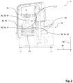
- the device 1 comprises a housing 4, which encloses an interior space 5 and which is provided with a closable opening 7 on two opposite side walls 6.
- the openings 7 form a feed opening 8 and a discharge opening, whereby only the feed opening 8 is shown in the figures.
- a conveyor belt 9 is arranged at each of the openings 7, whereby only the conveyor belt 9 associated with the feed opening 8 is shown in the figures.
- the conveyor belt 9 is provided for the initial placement of the food 2.
- the device 1 is provided with a stationary positioning device 10 in the form of a guide rail, which transfers the placed food item 2 into a starting position in which it rests centrally on the conveyor belt 9.
- a direction of movement 11 of the conveyor belt 9 is aligned parallel to a front side 12 of the device 1, wherein the direction of movement 11 of the conveyor belt 9 defines an X direction 13.
- the food item 2 is conveyed in the X direction 13 to the feed opening 8.
- the position is corrected by means of the positioning device 10, in that the food item 2 slides along the positioning direction 10 during the movement and is thereby displaced and aligned transversely to the direction of movement 11.
- a position of the positioning device 10 relative to the conveyor belt 9 is adjustable, so that the position of the food item 2 can be corrected depending on the width of the conveyor belt.
- the device 1 comprises a feed device 15 and a discharge device 16 in the form of a single conveyor belt 17 extending through the interior 5 of the device 1, wherein the strand-shaped food product 2 can be fed to a pressing chamber 18 arranged in the interior 5 of the device 1 by means of the conveyor belt 17 and can be discharged from the pressing chamber 18.
- a direction of movement 19 of the conveyor belt 17 also runs in the X direction 13.
- the food 2 can be conveyed to a cutting device, also not shown in the figures, which cuts the shaped food 2 into slices.
- the food product 2 is transferred from the first conveyor belt 9 to the second conveyor belt 17, from which the food product 2 is transferred to the last conveyor belt, wherein a respective width 14 of the conveyor belts 9, 17 corresponds.
- the first conveyor belt 9 extends partially into the interior 5 of the device 1, so that a transfer of the food product 2 takes place in the interior 5 of the device 1.
- a feeding of the food product 2 into the pressing chamber 18 and a discharge of the same thus take place on two opposite sides of the pressing chamber 18.
- the food product 2 is continuously moved in the X-direction 13, so that the starting position of the food product 2 - relative to the width of the conveyor belts 9, 17 - corresponds to an end position of the the same after passing through the device 1, so that the starting position for the subsequent cutting device can essentially be specified as soon as it is placed on the first conveyor belt 9. All three conveyor belts run in a horizontal direction and the surfaces of the upper strands are at the same level when viewed in the Z direction.
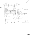
- the pressing chamber 18, consisting of six walls 20, is arranged in the interior 5 of the device 1, four of which are designed as pressing rams 28, 29, 30, 31 and are each movable in different directions by means of an associated pressing device 21, 22, 23, 24.
- a wall 20 forming a front side 25 of the pressing chamber 18 and a wall 20 forming a bottom 26 of the pressing chamber 18 are firmly connected to the device 1 and its machine frame, while the remaining walls 20 form movable pressing rams 28, 29, 30, 31, each of which is displaceable in one direction relative to the machine frame and to the food 2.
- the pressing rams 28, 29, 30, 31 are each coupled to a pressing device 21, 22, 23, 24, each in the form of an electromechanical cylinder driven by a servomotor.
- the thickness of the wall 20 forming the front side 25 of the pressing chamber 18 is adjustable to adapt to a cutting cross-section of the device 1, so that the pressing chamber 18 can be adapted to a width of the food product 2 to be formed.
- the wall 20 forming the floor 26 of the pressing chamber 18 is fixedly mounted in the machine frame and covered with the second conveyor belt 17, wherein the floor 26 is enclosed between an upper run 32 and a lower run 33 of the second conveyor belt 17.
- a width 14 of the second conveyor belt 17 is designed to be larger than a width 34 of the pressing chamber 18 measured transversely to the movement device 11 of the conveyor belt 17 in a final state, which in connection with the Figures 2 to 6 is described in detail.
- the floor 26 of the pressing chamber 18 is thus completely covered by the conveyor belt 17, so that during the forming process, pressing forces introduced into the food 2 in the Z direction are transferred from the food 2 via the conveyor belt 17 into the floor 26.
- the fourth press ram 31 forming a rear side 35 of the press chamber 18 is movable in a Y-direction 36 running perpendicular to the X-direction 13, wherein the first press ram 28 forming a top side 37 of the press chamber 18 is movable in a Z-direction 38, the is oriented perpendicular to the X-direction 13 and the Y-direction 36.
- the upper side 37 of the pressing chamber 18 is circularly arc-shaped when viewed in a vertical cross-section.
- the second and third pressing rams 29, 30 forming the two remaining sides 27 of the pressing chamber 18 are movable in the X-direction 13 and counter to the X-direction 13, respectively, wherein the second and third pressing rams 29, 30, with their pressing devices 22, 23, are coupled to the first pressing ram 28 and its associated pressing device 21 in such a way that they move along with a movement of the upper side 37 in the Z-direction 36.
- the respective pressing ram 29, 30 has a contact element 42 which is arranged at an end facing the foodstuff 2. In the final state of the pressing chamber 18, the contact element 42 forms a contact surface which is in contact with the foodstuff 2.
- the respective contact surface 41 of the second and third press rams 29, 30 is designed to be variable in size.
- the contact element 42 is designed as a folded sheet metal, which is movably attached to the respective press ram 29, 30 on the one hand and fixedly attached to the first press ram 28 on the other hand by means of a spring, so that a relative movement between the respective press ram 29, 30 and the first press ram 28 is possible.
- the first press ram 28, with its pressing device 21, is coupled to the second and third press rams 29, 30 and the associated pressing device 22, 23 by means of a linear guide.
- the spring In the initial state of the press chamber 18, the spring is deflected by the respective press ram 29, 30 due to gravity in such a way that a section of the contact element 42 protrudes above a surface of the respective press ram 29, 30.
- the press chamber 18 can be transferred from its initial state to a final state in which it has a second enclosed volume.
- the walls 20 of the press chamber 18, which are designed as press rams 28, 29, 30, 31 and together form a "half-chamber,” are moved relative to the food 2.
- the final state of the press chamber is shown in the Figures 4 and 6 shown.
- the pressing chamber 18 is first returned to its initial state by opening the pressing chamber 18.
- the first Press ram 28 of the press chamber 18 with the second and third press ram 29, 30 is moved against the Y-direction 36, so that an opening cross-section 40 is released, which fits well in the Figure 2a can be seen.
- the opening cross-section 40 of the pressing chamber 18 exceeds a cross-section of the food 2, so that the same can be fed into the pressing chamber 18.
- the food 2 which has been tempered for better formability such that a temperature at least in the edge regions of the food 2 is reduced compared to a temperature of the food 2 in a core region, is then introduced into the pressing chamber 18 by means of the first conveyor belt 9.
- the food 2 has been placed on the first conveyor belt 9 by means of the positioning device 10 such that, upon introduction into the pressing chamber 18, it lies close to the wall 20 forming the rear side 35, as shown in Figure 2 is shown.
- the length of the food 2 is measured by means of a light barrier not shown in the figures.
- the feed opening 8 is closed again by means of a closing element and the food is transferred to the second conveyor belt and aligned centrally relative to the pressing chamber.
- the second and third pressing rams 29, 30 are already moved in the X-direction 13 and opposite to the X-direction 13, so that a distance between the two pressing rams 29, 30 is reduced such that it essentially corresponds to a length of the food 2, preferably slightly exceeds it.
- the second conveyor belt 17 is stopped. Subsequently - as can be clearly seen in the Figure 3 can be seen - which moves the press ram 31 forming the back 35 of the pressing chamber 18 in such a way that it comes into contact with the food 2.
- the food 2 escapes in the X-direction 36 and in the Z-direction 38.
- the first press ram 28 is brought into contact with the food 2 by moving the same in the Z-direction 38, as can be seen from Figure 4 can be seen.
- the press ram 28 comes into contact with the food 2.
- the contact elements 42 are initially still deflected.
- the second and third press rams 29, 30 come into contact with the conveyor belt 17.
- the linear guide in conjunction with the spring then makes it possible to move the first press ram 28 further in the Z-direction 38 by moving the contact element 42 in the Z-direction 38, so that the contact surface 41 of the respective press ram 29, 30 in the size is reduced.
- the food 2 is thus compressed in the Z-direction 38, causing an increased expansion of the food 2 in the X-direction 13 as well as against the X-direction 13, while a cross-section of the food 2 parallel to a YZ plane already corresponds to a "final cross-section" of the pressing chamber 18.
- the pressing rams 29, 30 forming the sides 27 of the pressing chamber 18 are moved in the X-direction 13 and against the X-direction 13, respectively, in order to come into contact with the food 2, as shown in the Figures 5 and 6 can be seen.
- the pressing chamber 18 is thus in its final state, in which all walls 20 of the pressing chamber 18 are in contact with the food 2 and pressing forces are introduced into the food 2 by the pressing rams 28, 29, 30, 31.
- the food 2, which is enclosed in an interior 39 of the pressing chamber 18, is thereby transferred into a shaped state, which in the Figure 8 is recognizable and should be as close as possible to a cuboid.
- the food product 2 is conveyed in the X direction 13 out of the pressing chamber 18 and the interior 5 of the device 1 by means of the second conveyor belt 17.
- the first pressing ram 28 of the pressing chamber 18, together with the second and third pressing rams 29, 30, is again moved counter to the Y direction 36, so that a second opening cross-section opposite the first opening cross-section 40 is released, which exceeds a cross-section of the food product 2, so that the food product 2 can be removed from the pressing chamber 18.
- the food product 2 is transferred to the third conveyor belt, by means of which the food product 2 can be transported to the cutting machine.
Landscapes
- Life Sciences & Earth Sciences (AREA)
- Engineering & Computer Science (AREA)
- Food Science & Technology (AREA)
- Wood Science & Technology (AREA)
- Zoology (AREA)
- Health & Medical Sciences (AREA)
- Nutrition Science (AREA)
- Chemical & Material Sciences (AREA)
- Polymers & Plastics (AREA)
- Formation And Processing Of Food Products (AREA)
- Meat, Egg Or Seafood Products (AREA)
Claims (7)
- Dispositif (1) destiné à former une denrée alimentaire en forme de boudin (2) en particulier une pièce de viande (3), avec une chambre de pressage (18), qui est limitée par des parois (20) desquelles au moins une est constituée mobile au moyen d'un dispositif de pressage (21, 22, 23, 24)et sous la forme d'un piston de presse (28, 29, 30, 31), la chambre de pressage (18) pouvant être transférée d'un état initial avec un premier volume confiné à un état final avec un deuxième volume confiné, sachant que le dispositif comporte un système d'alimentation (15) au moyen duquel la denrée alimentaire (2) peut être acheminée (40) à la chambre de pressage (18) par une première section d'ouverture et comporte un système d'évacuation (16), au moyen duquel la denrée alimentaire (2) peut être évacuée par une deuxième section d'ouverture hors de la chambre de pressage (18), sachant que la première section d'ouverture (40) est opposée à la deuxième section d'ouverture de telle manière que la denrée alimentaire (2) peut être acheminée et évacuée de préférence dans la même direction,
caractérisé en ce que
la chambre de pressage (18) est composée de six parois (20) dont quatre sont constituées sous la forme de pistons de presse (28, 29, 30, 31) et peuvent être respectivement déplacées dans des directions différentes au moyen d'un système de pressage correspondant (21, 22, 23, 24). - Procédé destiné à former une denrée alimentaire en forme de boudin (2), en particulier une pièce de viande (3), avec les étapes de procédé suivantes :a) une chambre de pressage (18) délimitée par des parois (20) est ouverte dans laquelle au moins une des parois (20) est déplacée par rapport à au moins une autre des parois (20), une section d'ouverture (40) étant de ce fait libérée,b) la denrée alimentaire (2) est introduite par la section d'ouverture (40) dans la chambre de pressage (18),c) la section d'ouverture (40) de la chambre de pressage (18) est à nouveau fermée et la denrée alimentaire (2) est transférée par le déplacement des parois (20) de la chambre de pressage (18) d'un état non formé à un état formé,d) une section d'ouverture de la chambre de pressage (18) est libérée et la denrée alimentaire (2) formée est évacuée par cette section d'ouverture hors de la chambre de pressage (18),e) l'acheminement de la denrée alimentaire (2) non formée dans la chambre de pressage (18) et l'évacuation de la denrée alimentaire (2) formée hors de la chambre de pressage (18) ont lieu sur les côtés opposés (27) de la chambre de pressage (18), de préférence par déplacement de la denrée alimentaire (2) dans la même direction,
caractérisé en ce quef) la chambre de pressage (18) est composée de six parois (20) dont quatre sont constituées sous la forme de pistons de presse (28, 29, 30, 31) et peuvent être respectivement déplacées dans des directions différentes au moyen d'un système de pressage correspondant (21, 22, 23, 24). - Procédé selon la revendication 2, caractérisé en ce que la denrée alimentaire (2) non formée est acheminée à la chambre de pressage (18) au moyen d'une bande transporteuse (9), qui s'étend de préférence dans la chambre de pressage (18) et couvre en plus de préférence au moins en partie une paroi (20) de la chambre de pressage (18) et encore en plus tourne de préférence autour d'une paroi (20) de la chambre de pressage (18).
- Procédé selon la revendication 2 ou 3, caractérisé en ce que la denrée alimentaire (2) formée est évacuée de la chambre de pressage (18) au moyen d'une bande transporteuse, qui s'étend de préférence dans la chambre de pressage (18) et couvre en plus de préférence au moins en partie une paroi (20) de la chambre de pressage (18) et encore en plus tourne de préférence autour d'une paroi (20) de la chambre de pressage (18).
- Procédé selon l'une quelconque des revendications 2 à 4, caractérisé en ce que l'acheminement de la denrée alimentaire (2) non formée (2) dans la chambre de pressage (18) et l'évacuation de la denrée alimentaire (2) formée de la chambre de pressage (18) ont lieu au moyen de la même bande transporteuse (17).
- Procédé selon l'une quelconque des revendications 2 à 5, caractérisé en ce qu'une température de la denrée alimentaire (2) est au moins dans les zones de bord plus faible qu'une température de la denrée alimentaire (2) dans une zone centrale.
- Procédé selon l'une quelconque des revendications 2 à 6, caractérisé en ce qu'au moins une paroi (20) constituée sous la forme d'un piston de presse (29, 30) est déplacée pendant l'introduction de la denrée alimentaire (2) dans la chambre de pressage (18) perpendiculairement et/ou parallèlement à un sens de déplacement (19) de la denrée alimentaire (2), dans lequel la denrée alimentaire (2) est acheminée à la chambre de pressage (18), de préférence dans le sens de déplacement (19) ou perpendiculairement à celui-ci de telle manière qu'une distance entre la paroi (20) et une paroi opposée (20) de la chambre de pressage (18) est réduite.
Applications Claiming Priority (2)
| Application Number | Priority Date | Filing Date | Title |
|---|---|---|---|
| DE102020103311.7A DE102020103311A1 (de) | 2020-02-10 | 2020-02-10 | Vorrichtung und Verfahren zum Formen eines strangförmigen Lebensmittels |
| PCT/EP2021/052965 WO2021160563A1 (fr) | 2020-02-10 | 2021-02-08 | Dispositif et procédé de mise en forme d'aliment de type boudin |
Publications (3)
| Publication Number | Publication Date |
|---|---|
| EP4102976A1 EP4102976A1 (fr) | 2022-12-21 |
| EP4102976B1 true EP4102976B1 (fr) | 2025-06-11 |
| EP4102976B8 EP4102976B8 (fr) | 2025-07-16 |
Family
ID=74572782
Family Applications (1)
| Application Number | Title | Priority Date | Filing Date |
|---|---|---|---|
| EP21704253.0A Active EP4102976B8 (fr) | 2020-02-10 | 2021-02-08 | Dispositif et procédé pour façonner un produit alimentaire de forme allongée |
Country Status (6)
| Country | Link |
|---|---|
| US (1) | US20230049142A1 (fr) |
| EP (1) | EP4102976B8 (fr) |
| CN (1) | CN115003161A (fr) |
| DE (1) | DE102020103311A1 (fr) |
| DK (1) | DK4102976T3 (fr) |
| WO (1) | WO2021160563A1 (fr) |
Families Citing this family (1)
| Publication number | Priority date | Publication date | Assignee | Title |
|---|---|---|---|---|
| DE102021126430A1 (de) * | 2021-10-12 | 2023-04-13 | Textor Maschinenbau GmbH | Presseinrichtung |
Citations (1)
| Publication number | Priority date | Publication date | Assignee | Title |
|---|---|---|---|---|
| EP1595456A2 (fr) * | 2004-05-13 | 2005-11-16 | Hoegger AG | Presse de moulage et procédé de pressage de viande |
Family Cites Families (18)
| Publication number | Priority date | Publication date | Assignee | Title |
|---|---|---|---|---|
| US3040654A (en) * | 1959-11-03 | 1962-06-26 | Opie John | Machines for compressing meat |
| BE786744A (fr) * | 1971-07-26 | 1973-01-26 | Chemetron Corp | Presse ayant un cycle de fonctionnement semi-automatique |
| DE2140585A1 (de) | 1971-08-13 | 1973-02-22 | Ernst Holz | Speckpresse |
| DE3708387A1 (de) * | 1987-03-14 | 1988-09-22 | Schneider Gmbh & Co Kg Fleisch | Vorrichtung zum umformen von lebensmitteln, insbesondere von fleischwaren, in eine vorgegebene gestalt |
| US4967652A (en) * | 1988-12-15 | 1990-11-06 | Oscar Mayer Foods Corporation | Pressing system for shaping bacon bellies and the like |
| AU2006206275B2 (en) * | 2005-01-22 | 2012-01-19 | Blentech Corporation | Semi-continuous meat press method and apparatus |
| DE202005018374U1 (de) | 2005-11-23 | 2006-04-06 | Ulbricht, Christian | Pressvorrichtung zum Formen von Fleischwaren |
| CA2676361A1 (fr) * | 2007-01-23 | 2008-07-31 | Formax, Inc. | Machine a mouler des galettes alimentaires |
| US8424430B2 (en) * | 2007-08-09 | 2013-04-23 | Kraft Foods Group Brands Llc | Food product conveyor and handling systems |
| ES2450240T3 (es) * | 2007-10-25 | 2014-03-24 | Nienstedt Gmbh | Procedimiento para producir productos alimenticios conformados |
| DE102009024189A1 (de) * | 2009-06-08 | 2010-12-09 | Weber Maschinenbau Gmbh Breidenbach | Verarbeitungsvorrichtung für Lebensmittelprodukte |
| JP2012035314A (ja) * | 2010-08-10 | 2012-02-23 | Kikusui Seisakusho Ltd | 粉体圧縮成形機 |
| US9487444B2 (en) * | 2011-04-22 | 2016-11-08 | Mass S.P.A. | Apparatuses, system and methods for forming pressed articles and pressed articles formed thereby |
| LU92917B1 (de) * | 2015-12-17 | 2017-06-19 | Sms Group Gmbh | Strang- und Rohrpresse bzw. Metallstrangpresse |
| DE202016102297U1 (de) | 2016-04-29 | 2016-06-24 | Anton & Völkl Patente GmbH & Co. KG | Presse |
| DE102018106299B3 (de) * | 2018-03-19 | 2019-06-19 | Tvi Entwicklung Und Produktion Gmbh | Verfahren zum Verformen und Frosten eines ungleichmäßig geformten, länglichen Laibes sowie hierfür geeignete Vorrichtungen |
| DE102018106300B4 (de) * | 2018-03-19 | 2024-03-14 | Tvi Entwicklung Und Produktion Gmbh | Verfahren zum Verpressen und Aufschneiden von elastischen Laiben sowie Schneidemaschine hierfür |
| KR101970821B1 (ko) * | 2018-12-26 | 2019-04-23 | (주)아그로시스템즈 | 포앙식품용 성형 컨베이어 장치 |
-
2020
- 2020-02-10 DE DE102020103311.7A patent/DE102020103311A1/de not_active Withdrawn
-
2021
- 2021-02-08 US US17/797,283 patent/US20230049142A1/en active Pending
- 2021-02-08 WO PCT/EP2021/052965 patent/WO2021160563A1/fr not_active Ceased
- 2021-02-08 CN CN202180009094.7A patent/CN115003161A/zh active Pending
- 2021-02-08 EP EP21704253.0A patent/EP4102976B8/fr active Active
- 2021-02-08 DK DK21704253.0T patent/DK4102976T3/da active
Patent Citations (1)
| Publication number | Priority date | Publication date | Assignee | Title |
|---|---|---|---|---|
| EP1595456A2 (fr) * | 2004-05-13 | 2005-11-16 | Hoegger AG | Presse de moulage et procédé de pressage de viande |
Also Published As
| Publication number | Publication date |
|---|---|
| DE102020103311A1 (de) | 2021-08-12 |
| EP4102976A1 (fr) | 2022-12-21 |
| WO2021160563A1 (fr) | 2021-08-19 |
| EP4102976B8 (fr) | 2025-07-16 |
| CN115003161A (zh) | 2022-09-02 |
| US20230049142A1 (en) | 2023-02-16 |
| DK4102976T3 (da) | 2025-09-08 |
Similar Documents
| Publication | Publication Date | Title |
|---|---|---|
| EP3448641B1 (fr) | Trancheuse et procédé pour trancher des boudins élastiques, en particulier des boudins de viande | |
| DE69206105T2 (de) | Verfahren und Vorrichtung zum Zuführen eines gleichmässigen Brotteigstreifens. | |
| DE69019975T2 (de) | Verfahren und Vorrichtung zum Herstellen von Nahrungsmitteln durch Koch-Koextrusion. | |
| DE3025507A1 (de) | Verfahren und vorrichtung zum formen und verpacken von gegenstaenden aus einer weichen masse | |
| DE60225657T2 (de) | Verfahren und Vorrichtung zum Ausstanzen tiefgezogener Formteile, die noch teilweise mit der Restbahn verbunden sind und damit entformt werden | |
| EP4102975B1 (fr) | Dispositif et procédé pour façonner un produit alimentaire de forme allongée | |
| DE102020115748A1 (de) | Presseinrichtung | |
| DE60219707T2 (de) | Verfahren und Vorrichtung zum Schneiden und Formen von Bandelementen aus Gummi | |
| EP3760049A1 (fr) | Élément de contact pour un agencement de presse et agencement de presse | |
| EP3566985B1 (fr) | Dispositif d'empilement de plateaux pourvu d'un moyen de décharge | |
| EP4102976B1 (fr) | Dispositif et procédé pour façonner un produit alimentaire de forme allongée | |
| DE3908867C2 (fr) | ||
| DE69101374T2 (de) | Verpackungsmaschine und -verfahren mit servomotor für schrittweisen antrieb. | |
| DE69304141T2 (de) | Vorrichtung zum Teilen von Brotteig oder dergleichen | |
| WO2021160554A2 (fr) | Dispositif et procédé permettant la mise en forme d'un produit alimentaire de forme allongée | |
| EP3359356B1 (fr) | Dispositif pour couper un tronçon d'aliments | |
| EP2435198B1 (fr) | Serre-flan flexible pour installations de profilage continu | |
| EP1595456A2 (fr) | Presse de moulage et procédé de pressage de viande | |
| EP2713708A1 (fr) | Procédé pour façonner et faire refroidir une masse de fromage fondue préalablement chaude et par conséquent coulante | |
| EP3898137B1 (fr) | Unité presse pour machine à diviser en portions | |
| DE102006045477A1 (de) | Arbeitsstation für eine Tiefziehmaschine | |
| DE10357391A1 (de) | Verfahren zur Herstellung von Döner Kebab sowie eine Maschine zur Durchführung des Verfahrens | |
| DE19921047A1 (de) | Vorrichtung zum Portionieren eines Fleischstücks | |
| AT402166B (de) | Vorrichtung zum formen formbeständiger ballenartiger formkörper aus dünnfasrigem metall | |
| DE102024106754B4 (de) | Längstrennschweißeinrichtung mit Austreibvorrichtung |
Legal Events
| Date | Code | Title | Description |
|---|---|---|---|
| STAA | Information on the status of an ep patent application or granted ep patent |
Free format text: STATUS: UNKNOWN |
|
| STAA | Information on the status of an ep patent application or granted ep patent |
Free format text: STATUS: THE INTERNATIONAL PUBLICATION HAS BEEN MADE |
|
| PUAI | Public reference made under article 153(3) epc to a published international application that has entered the european phase |
Free format text: ORIGINAL CODE: 0009012 |
|
| STAA | Information on the status of an ep patent application or granted ep patent |
Free format text: STATUS: REQUEST FOR EXAMINATION WAS MADE |
|
| 17P | Request for examination filed |
Effective date: 20220809 |
|
| AK | Designated contracting states |
Kind code of ref document: A1 Designated state(s): AL AT BE BG CH CY CZ DE DK EE ES FI FR GB GR HR HU IE IS IT LI LT LU LV MC MK MT NL NO PL PT RO RS SE SI SK SM TR |
|
| DAV | Request for validation of the european patent (deleted) | ||
| DAX | Request for extension of the european patent (deleted) | ||
| GRAP | Despatch of communication of intention to grant a patent |
Free format text: ORIGINAL CODE: EPIDOSNIGR1 |
|
| STAA | Information on the status of an ep patent application or granted ep patent |
Free format text: STATUS: GRANT OF PATENT IS INTENDED |
|
| INTG | Intention to grant announced |
Effective date: 20250311 |
|
| GRAS | Grant fee paid |
Free format text: ORIGINAL CODE: EPIDOSNIGR3 |
|
| GRAA | (expected) grant |
Free format text: ORIGINAL CODE: 0009210 |
|
| STAA | Information on the status of an ep patent application or granted ep patent |
Free format text: STATUS: THE PATENT HAS BEEN GRANTED |
|
| REG | Reference to a national code |
Ref country code: DE Ref legal event code: R081 Ref document number: 502021007702 Country of ref document: DE Owner name: MAREL TREIF GMBH, DE Free format text: FORMER OWNER: ANMELDERANGABEN UNKLAR / UNVOLLSTAENDIG, 80297 MUENCHEN, DE |
|
| AK | Designated contracting states |
Kind code of ref document: B1 Designated state(s): AL AT BE BG CH CY CZ DE DK EE ES FI FR GB GR HR HU IE IS IT LI LT LU LV MC MK MT NL NO PL PT RO RS SE SI SK SM TR |
|
| P01 | Opt-out of the competence of the unified patent court (upc) registered |
Free format text: CASE NUMBER: APP_21364/2025 Effective date: 20250506 |
|
| REG | Reference to a national code |
Ref country code: GB Ref legal event code: FG4D Free format text: NOT ENGLISH |
|
| REG | Reference to a national code |
Ref country code: CH Ref legal event code: EP |
|
| RAP2 | Party data changed (patent owner data changed or rights of a patent transferred) |
Owner name: MAREL TREIF GMBH |
|
| REG | Reference to a national code |
Ref country code: DE Ref legal event code: R096 Ref document number: 502021007702 Country of ref document: DE |
|
| REG | Reference to a national code |
Ref country code: CH Ref legal event code: PK Free format text: BERICHTIGUNG B8 |
|
| REG | Reference to a national code |
Ref country code: IE Ref legal event code: FG4D Free format text: LANGUAGE OF EP DOCUMENT: GERMAN |
|
| REG | Reference to a national code |
Ref country code: CH Ref legal event code: PK Free format text: BERICHTIGUNG B8 |
|
| REG | Reference to a national code |
Ref country code: DK Ref legal event code: T3 Effective date: 20250903 |
|
| REG | Reference to a national code |
Ref country code: NL Ref legal event code: FP |
|
| PG25 | Lapsed in a contracting state [announced via postgrant information from national office to epo] |
Ref country code: ES Free format text: LAPSE BECAUSE OF FAILURE TO SUBMIT A TRANSLATION OF THE DESCRIPTION OR TO PAY THE FEE WITHIN THE PRESCRIBED TIME-LIMIT Effective date: 20250611 Ref country code: FI Free format text: LAPSE BECAUSE OF FAILURE TO SUBMIT A TRANSLATION OF THE DESCRIPTION OR TO PAY THE FEE WITHIN THE PRESCRIBED TIME-LIMIT Effective date: 20250611 |
|
| REG | Reference to a national code |
Ref country code: LT Ref legal event code: MG9D |
|
| PG25 | Lapsed in a contracting state [announced via postgrant information from national office to epo] |
Ref country code: NO Free format text: LAPSE BECAUSE OF FAILURE TO SUBMIT A TRANSLATION OF THE DESCRIPTION OR TO PAY THE FEE WITHIN THE PRESCRIBED TIME-LIMIT Effective date: 20250911 Ref country code: GR Free format text: LAPSE BECAUSE OF FAILURE TO SUBMIT A TRANSLATION OF THE DESCRIPTION OR TO PAY THE FEE WITHIN THE PRESCRIBED TIME-LIMIT Effective date: 20250912 |
|
| PG25 | Lapsed in a contracting state [announced via postgrant information from national office to epo] |
Ref country code: BG Free format text: LAPSE BECAUSE OF FAILURE TO SUBMIT A TRANSLATION OF THE DESCRIPTION OR TO PAY THE FEE WITHIN THE PRESCRIBED TIME-LIMIT Effective date: 20250611 |
|
| PG25 | Lapsed in a contracting state [announced via postgrant information from national office to epo] |
Ref country code: HR Free format text: LAPSE BECAUSE OF FAILURE TO SUBMIT A TRANSLATION OF THE DESCRIPTION OR TO PAY THE FEE WITHIN THE PRESCRIBED TIME-LIMIT Effective date: 20250611 |
|
| PG25 | Lapsed in a contracting state [announced via postgrant information from national office to epo] |
Ref country code: RS Free format text: LAPSE BECAUSE OF FAILURE TO SUBMIT A TRANSLATION OF THE DESCRIPTION OR TO PAY THE FEE WITHIN THE PRESCRIBED TIME-LIMIT Effective date: 20250911 |
|
| PG25 | Lapsed in a contracting state [announced via postgrant information from national office to epo] |
Ref country code: LV Free format text: LAPSE BECAUSE OF FAILURE TO SUBMIT A TRANSLATION OF THE DESCRIPTION OR TO PAY THE FEE WITHIN THE PRESCRIBED TIME-LIMIT Effective date: 20250611 |
|
| PG25 | Lapsed in a contracting state [announced via postgrant information from national office to epo] |
Ref country code: PT Free format text: LAPSE BECAUSE OF FAILURE TO SUBMIT A TRANSLATION OF THE DESCRIPTION OR TO PAY THE FEE WITHIN THE PRESCRIBED TIME-LIMIT Effective date: 20251013 |
|
| PG25 | Lapsed in a contracting state [announced via postgrant information from national office to epo] |
Ref country code: IS Free format text: LAPSE BECAUSE OF FAILURE TO SUBMIT A TRANSLATION OF THE DESCRIPTION OR TO PAY THE FEE WITHIN THE PRESCRIBED TIME-LIMIT Effective date: 20251011 |
|
| PG25 | Lapsed in a contracting state [announced via postgrant information from national office to epo] |
Ref country code: SM Free format text: LAPSE BECAUSE OF FAILURE TO SUBMIT A TRANSLATION OF THE DESCRIPTION OR TO PAY THE FEE WITHIN THE PRESCRIBED TIME-LIMIT Effective date: 20250611 |
|
| PG25 | Lapsed in a contracting state [announced via postgrant information from national office to epo] |
Ref country code: CZ Free format text: LAPSE BECAUSE OF FAILURE TO SUBMIT A TRANSLATION OF THE DESCRIPTION OR TO PAY THE FEE WITHIN THE PRESCRIBED TIME-LIMIT Effective date: 20250611 |
|
| PG25 | Lapsed in a contracting state [announced via postgrant information from national office to epo] |
Ref country code: PL Free format text: LAPSE BECAUSE OF FAILURE TO SUBMIT A TRANSLATION OF THE DESCRIPTION OR TO PAY THE FEE WITHIN THE PRESCRIBED TIME-LIMIT Effective date: 20250611 |
|
| PG25 | Lapsed in a contracting state [announced via postgrant information from national office to epo] |
Ref country code: SK Free format text: LAPSE BECAUSE OF FAILURE TO SUBMIT A TRANSLATION OF THE DESCRIPTION OR TO PAY THE FEE WITHIN THE PRESCRIBED TIME-LIMIT Effective date: 20250611 |
|
| PGFP | Annual fee paid to national office [announced via postgrant information from national office to epo] |
Ref country code: NL Payment date: 20260121 Year of fee payment: 6 |
|
| REG | Reference to a national code |
Ref country code: CH Ref legal event code: U11 Free format text: ST27 STATUS EVENT CODE: U-0-0-U10-U11 (AS PROVIDED BY THE NATIONAL OFFICE) Effective date: 20260301 |
|
| PGFP | Annual fee paid to national office [announced via postgrant information from national office to epo] |
Ref country code: GB Payment date: 20260122 Year of fee payment: 6 |
|
| PGFP | Annual fee paid to national office [announced via postgrant information from national office to epo] |
Ref country code: DK Payment date: 20260121 Year of fee payment: 6 Ref country code: DE Payment date: 20260121 Year of fee payment: 6 |
|
| PG25 | Lapsed in a contracting state [announced via postgrant information from national office to epo] |
Ref country code: IT Free format text: LAPSE BECAUSE OF FAILURE TO SUBMIT A TRANSLATION OF THE DESCRIPTION OR TO PAY THE FEE WITHIN THE PRESCRIBED TIME-LIMIT Effective date: 20250611 |
|
| PGFP | Annual fee paid to national office [announced via postgrant information from national office to epo] |
Ref country code: BE Payment date: 20260121 Year of fee payment: 6 |
|
| PLBE | No opposition filed within time limit |
Free format text: ORIGINAL CODE: 0009261 |
|
| STAA | Information on the status of an ep patent application or granted ep patent |
Free format text: STATUS: NO OPPOSITION FILED WITHIN TIME LIMIT |
|
| PGFP | Annual fee paid to national office [announced via postgrant information from national office to epo] |
Ref country code: FR Payment date: 20260121 Year of fee payment: 6 |
|
| REG | Reference to a national code |
Ref country code: CH Ref legal event code: L10 Free format text: ST27 STATUS EVENT CODE: U-0-0-L10-L00 (AS PROVIDED BY THE NATIONAL OFFICE) Effective date: 20260423 |