EP4103014B1 - Seitenzarge für einen schubkasten - Google Patents
Seitenzarge für einen schubkasten Download PDFInfo
- Publication number
- EP4103014B1 EP4103014B1 EP21703448.7A EP21703448A EP4103014B1 EP 4103014 B1 EP4103014 B1 EP 4103014B1 EP 21703448 A EP21703448 A EP 21703448A EP 4103014 B1 EP4103014 B1 EP 4103014B1
- Authority
- EP
- European Patent Office
- Prior art keywords
- adapter
- wall section
- vertical wall
- guide tab
- side frame
- Prior art date
- Legal status (The legal status is an assumption and is not a legal conclusion. Google has not performed a legal analysis and makes no representation as to the accuracy of the status listed.)
- Active
Links
Images






Classifications
-
- A—HUMAN NECESSITIES
- A47—FURNITURE; DOMESTIC ARTICLES OR APPLIANCES; COFFEE MILLS; SPICE MILLS; SUCTION CLEANERS IN GENERAL
- A47B—TABLES; DESKS; OFFICE FURNITURE; CABINETS; DRAWERS; GENERAL DETAILS OF FURNITURE
- A47B88/00—Drawers for tables, cabinets or like furniture; Guides for drawers
- A47B88/90—Constructional details of drawers
- A47B88/941—Drawers being constructed from two or more parts
Definitions
- the present invention relates to a side frame for a drawer according to the preamble of claim 1.
- the EP 2 852 303 B1 reveals a drawer with two side frames that surround an adapter. Elastic, deformable elevations are provided on each adapter in order to be deformed when a rear wall is inserted and then to lock the rear wall in the assembly position. Such locking means are intended to secure the floor in the longitudinal direction of a pull-out guide.
- the vertical wall section of the adapter is also flat so that the base can be inserted in the longitudinal direction.
- the WO 2012/065195 A1 discloses a support rail for a drawer bottom, which has a horizontal leg and a vertical web.
- a protruding stop is provided on the vertical web, which serves as an assembly aid in order to be able to assemble a floor of different thicknesses.
- a corner area can be stopped at the stop, which makes assembly more difficult and can lead to damage.
- a frame for a drawer which includes a frame base for fixing a base and a frame attachment.
- DE 10 2012 104 457 A1 discloses a fixing arrangement for fixing sheet metal parts to a drawer.
- the side frame according to the invention comprises a support rail with a horizontal support web with a base and a vertical wall section, wherein at least one adapter is fixed to the vertical wall section and a guide tab is arranged on the vertical wall section adjacent to the at least one adapter, which covers at least part of an edge of the adapter.
- the guide tab is integrally formed on the vertical wall section and covers at least part of an edge of the adapter.
- the guide tab is integrally formed on the adapter and dips into a recess in the vertical wall section, the coverage of at least part of an edge of the adapter then relating to a folding edge at which the guide tab is angled.
- the guide tab protrudes obliquely from a plane formed by the vertical wall section.
- the dimensionally stable guide tab can be either straight or curved.
- the guide tab is straight and projects, for example, at an angle between 2° and 20° to the plane of the vertical wall section.
- one end of the guide tab is aligned essentially flush with a surface of the adapter facing the floor.
- the end of the guide tab is an edge that is the greatest distance from the plane of the vertical wall section. This end or edge is thus aligned essentially in the same plane parallel to the vertical wall section as a surface of the adapter, so that there are no steps that could hinder the assembly process.
- a front and a rear adapter are fixed to the carrier rail, with at least one guide tab being arranged on each adapter. It is sufficient if a single guide tab is provided on the support rail for guiding the floor, although several guide tabs per adapter can optionally be provided vertically offset.
- Each adapter preferably comprises a metal sheet which rests on the vertical wall section on a side facing the floor, i.e. is arranged on the inside of the vertical wall section.
- the metal sheet of the adapter can, for example, have a thickness between 0.5 mm and 2 mm and thus forms a step on the vertical wall section, which is bridged by embossing the guide tab on the vertical wall section, so that the floor along the guide tab at the Assembly can be postponed.
- the adapters on the carrier rail are preferably arranged at the ends of the carrier rail.
- a front adapter can have means for fixing to a front panel and a rear adapter can have means for fixing a rear wall.
- more than two adapters can be fixed to the support rail.
- the guide tabs can be formed directly on the one or more adapters.
- An integrally formed projection is bent towards the vertical wall section.
- the vertical wall section has a recess into which the guide tab of the adapter can be inserted flush. This also ensures continuous guidance of the floor during the assembly process.
- a groove is preferably formed on the support rail between the vertical wall section and the horizontal support web. Bendable fastening elements, for example hooks or claws, can be provided on the groove, which can be driven into an underside of the base when it is arranged in the desired position.
- the side frame according to the invention is preferably used in a drawer in which an inlay is fixed between two adapters on the side frame.
- an inlay can be a plate-shaped element, for example made of glass, wood, plastic or metal, which is attached to the two adapters.
- a side frame 1 includes a support rail 2, to which a front adapter 3 and a rear adapter 4 are fixed.
- a cover 5 is mounted on the front adapter 3 and surrounds the adapter 3.
- a further cover 6 is arranged around the adapter 4 on the rear adapter 4.
- the Support rail 2 extends over the entire length of the side frame, but can optionally also be formed from individual rail sections.
- the support rail 2 comprises a horizontal support web 7 and a vertical wall section 8.
- a groove 9 is formed between the horizontal support web 7 and the vertical wall section 8, the groove bottom being arranged below the plane of the horizontal support web 7.
- integrally formed fastening elements 10, in particular bendable hooks, are provided, which can be driven into an underside of a floor.
- the guide tabs 12 and 13 are integrally formed from the vertical wall section 8, in particular by embossing, and are inclined aligned with the plane of the vertical wall section 8.
- FIG 2 the side frame 1 is shown without the covers 5 and 6. It can be seen that means 14 for attaching a front panel are formed on the front adapter 3, for example locking mechanisms.
- Means 15 for fastening a rear wall of a drawer are provided on the rear adapter 4, for example locking elements or sleeves into which screws can be screwed.
- a plate-shaped inlay can be inserted between the adapters 3 and 4, with a horizontal frame strip 11 and vertical frame strips 31 and 41 being formed for this purpose.
- the frame strips 31 and 41 have a U-shaped cross section.
- the adapter 3 includes a vertical frame strip 31 for fixing a front end of a plate-shaped inlay.
- the adapter 3 comprises a foot element 30, which is made, for example, from a metal sheet and rests on the inside of the vertical wall section 8.
- the guide tab 12 runs obliquely to the vertical wall section 8 and ends essentially with an outer end flush with an upper side of the foot element 30. This allows an edge of a base for the drawer to be moved along the vertical wall section 8 and is then guided over the guide tab 12 in order to avoid hitting the foot element 30.
- FIG 4 the front adapter 3 is shown from above when assembling a floor 16.
- the guide tab 12 protrudes inwards from the vertical wall section 8.
- the floor 16 is inserted along the vertical wall section 8 and then hits the guide tab 12, so that an edge of the floor 16 is moved away from the vertical wall section 8 and the floor 16 can be further moved along the vertical surface of the foot element 30.
- the fastening elements 10 protrude into the groove 9 on the support rail 2.
- FIG 5 the area of the foot element 30 on the adapter 3 is shown in a mounted position with a base 16 in a sectional view.
- the floor 16 can be made of a wood material and is mounted on the support web 7 of the support rail 2. An edge of the floor 16 is arranged on the foot element 30 and positioned at a distance from the vertical wall section 8.
- the carrier rail 2 is shown without the adapter.
- the guide tab 12 is integrally formed on the vertical wall portion 8 and protrudes inward.
- the adapter 3 can also be positioned and fixed to the guide rail 2 via the dimensionally stable guide tab 12.
- FIG. 7 the rear adapter 4 is shown, on which means 15 are provided for fixing a rear wall.
- a foot element 40 is provided, which is formed from a metal sheet and rests on an inside of the vertical wall section 8.
- a guide tab 13 is integrally formed on the vertical wall section 8, which is inclined and whose end is aligned essentially flush with a surface of the foot element 40 in order to form a step between the vertical wall section 8 and the foot element 40 Area of the guide tab 13 to avoid.
- a support 42 is formed on the rear adapter 4, which is aligned essentially flush with the horizontal support web 7 of the support rail 2 and serves to support and attach to the guide rail.
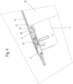
- FIG 9 the rear adapter 4 is shown when installing a floor 16.
- the floor 16 can be displaced along the vertical wall section 8 and then hits the guide tab 13, so that an edge of the floor 16 is moved away from the vertical wall section 8 and the floor 16 can be further displaced along the vertical surface of the foot element 40.
- Figure 10 the floor 16 is shown in a mounted position in a sectional view, and it can be seen that an edge of the floor 16 rests on the foot element 40 or elevations formed thereon and is arranged at a distance from the vertical wall section 8.
- FIG 11 the rear area of the support rail 2 is shown without an adapter.
- the guide tab 13 protrudes inwards from the vertical wall section 8 and can also be used to position the rear adapter 4 during assembly.
- FIG 12 a view of a further embodiment of the guide tab 32 is shown. Shown is the area of the front adapter 3 with the foot element 30 placed against the vertical wall section 8.
- the two embodiments differ in that the guide tab 32 has not been stamped into the vertical wall section 8, instead the adapter 3 or the foot element 30 points an integrally formed extension which forms the guide tab 32. This is bent in the direction of the vertical wall section 8 and dips into a recess 17 within the vertical wall section 8.
- This form of design also leads to a stepless displacement when assembling the base 16 without hooking an edge of the base 16 on the adapter 3 or the foot element 30.
- Figure 13 is an exploded view of the view Figure 12 shown.
- the guide tab 32 and the recess 17 can be seen particularly advantageously.
- the guide tab protrudes obliquely in the direction of the vertical wall section from the plane of the foot element 30 and protrudes with the free end obliquely in front of a plane formed by the vertical wall section 8 .
- Figure 14 a rear view of the front adapter 3 is shown. Here, in particular, the engagement of the guide tab 32 in the recess 17 in the vertical wall section 8 can be seen.
- the guide tab 32 can also be designed as part of the rear adapter 4 or the rear foot element 40.
Landscapes
- Drawers Of Furniture (AREA)
Description
- Die vorliegende Erfindung betrifft eine Seitenzarge für einen Schubkasten nach dem Oberbegriff des Anspruches 1.
- Die
EP 2 852 303 B1 offenbart einen Schubkasten mit zwei Seitenzargen, die einen Adapter umgreifen. An jedem Adapter sind elastische verformbare Erhebungen vorgesehen, um beim Einschieben einer Rückwand verformt zu werden und dann die Rückwand in der Montageposition zu verrasten. Solche Rastmittel sollen den Boden in Längsrichtung einer Auszugsführung sichern. Der vertikale Wandabschnitt des Adapters ist im Übrigen eben ausgebildet, um den Boden in Längsrichtung einführen zu können. - Die
WO 2012/065195 A1 offenbart eine Trägerschiene für einen Schubladenboden, die einen horizontal verlaufenden Schenkel und einen Vertikalsteg aufweist. An dem Vertikalsteg ist ein abstehender Anschlag vorgesehen, der als Montagehilfe dient, um einen Boden unterschiedlicher Dicke montieren zu können. Beim Einschieben eines dicken Bodens in Längsrichtung der Trägerschiene kann ein Eckbereich an dem Anschlag angehalten werden, was die Montage erschwert und zu einer Beschädigung führen kann. - In der
WO 2018/166838 A1 ist eine Zarge für einen Schubkasten offenbart, die einen Zargensockel zur Fixierung eines Bodens und einen Zargenaufsatz umfasst. -
DE 10 2012 104 457 A1 offenbart eine Fixierungsanordnung zur Fixierung von Blechteilen an einem Schubkasten. - Es ist daher Aufgabe der vorliegenden Erfindung, eine Seitenzarge für einen Schubkasten zu schaffen, die stabil aufgebaut ist und eine einfache Montage des Bodens ermöglicht.
- Diese Aufgabe wird mit einer Seitenzarge mit den Merkmalen des Anspruches 1 gelöst.
- Die erfindungsgemäße Seitenzarge umfasst eine Trägerschiene mit einem horizontalen Auflagesteg mit einem Boden und einem vertikalen Wandabschnitt, wobei an dem vertikalen Wandabschnitt mindestens ein Adapter festgelegt ist und benachbart zu dem mindestens einen Adapter eine Führungslasche an dem vertikalen Wandabschnitt angeordnet ist, die zumindest einen Teil einer Kante des Adapters überdeckt. Dadurch kann beim Montieren des Bodens der Boden mit seiner seitlichen Kante entlang dem vertikalen Wandabschnitt bewegt werden, ohne dass der Boden an dem Adapter anschlägt oder beschädigt werden kann. Der Boden kann dann entlang der Führungslasche bewegt werden, so dass eine Kante des Bodens sich von dem vertikalen Wandabschnitt an der Trägerschiene leicht abhebt und in Richtung des Adapters verschoben werden kann.
- Die Führungslasche ist nach einer ersten erfindungsgemäßen Variante an dem vertikalen Wandabschnitt integral ausgebildet und überdeckt zumindest einen Teil einer Kante des Adapters. Alternativ ist die Führungslasche nach einer zweiten erfindungsgemäßen Variante an dem Adapter integral ausgebildet ist und taucht in eine Aussparung in dem vertikalen Wandabschnitt ein, wobei die Überdeckung zumindest eines Teils einer Kante des Adapters sich dann auf eine Knickkante bezieht, an der die Führungslasche abgewinkelt ist. Erfindungsgemäß steht die Führungslasche schräg von einer durch den vertikalen Wandabschnitt gebildeten Ebene hervor. Dabei kann die formstabile Führungslasche wahlweise gerade oder gebogen ausgebildet sein. Vorzugsweise ist die Führungslasche gerade ausgebildet und steht beispielsweise in einem Winkel zwischen 2° und 20° zu der Ebene des vertikalen Wandabschnittes hervor.
- Ein Ende der Führungslasche ist erfindungsgemäß im Wesentlichen flächenbündig mit einer dem Boden zugewandten Oberfläche des Adapters ausgerichtet. Das Ende der Führungslasche ist dabei eine Kante, die die größte Entfernung zu der Ebene des vertikalen Wandabschnittes besitzt. Dieses Ende bzw. diese Kante ist somit im Wesentlichen in der gleichen Ebene parallel zu dem vertikalen Wandabschnitt wie eine Oberfläche des Adapters ausgerichtet, so dass keine Stufen vorhanden sind, die den Montagevorgang behindern könnten.
- An der Trägerschiene sind in einer Ausgestaltung ein vorderer und ein hinterer Adapter festgelegt, wobei an jedem Adapter mindestens eine Führungslasche angeordnet ist. Es reicht aus, wenn an der Trägerschiene eine einzige Führungslasche zum Führen des Bodens vorgesehen ist, allerdings können vertikal versetzt optional auch mehrere Führungslaschen pro Adapter vorgesehen sein.
- Jeder Adapter umfasst vorzugsweise ein Metallblech, das an einer zum Boden gewandten Seite auf dem vertikalen Wandabschnitt aufliegt, also an der Innenseite des vertikalen Wandabschnittes angeordnet ist. Das Metallblech des Adapters kann beispielsweise eine Dicke zwischen 0,5 mm bis 2 mm besitzen und bildet somit eine Stufe an dem vertikalen Wandabschnitt aus, die über das Prägen der Führungslasche an dem vertikalen Wandabschnitt überbrückt wird, so dass der Boden entlang der Führungslasche bei der Montage verschoben werden kann.
- Die Adapter an der Trägerschiene sind vorzugsweise endseitig an der Trägerschiene angeordnet. Dabei kann ein vorderer Adapter Mittel zur Fixierung an einer Frontblende und ein hinterer Adapter Mittel zur Fixierung einer Rückwand aufweisen. Optional können auch mehr als zwei Adapter an der Trägerschiene fixiert werden.
- In einer weiteren Ausführungsform können die Führungslaschen direkt an dem einen oder den mehreren Adaptern ausgeprägt sein. Dabei wird ein integral angeformter Überstand hin zu dem vertikalen Wandabschnitt gebogen. Des Weiteren weist der vertikale Wandabschnitt eine Aussparung auf, in die die Führungslasche vom Adapter bündig eintauchen kann. Dadurch wird ebenfalls eine stufenlose Führung des Bodens im Montagevorgang gewährleistet.
- Für eine einfache Montage des Bodens kann dieser auf den horizontalen Auflagesteg aufgesetzt und in Längsrichtung verschoben werden. Dabei ist vorzugsweise zwischen dem vertikalen Wandabschnitt und dem horizontalen Auflagesteg eine Nut an der Trägerschiene ausgebildet. An der Nut können biegbare Befestigungselemente, beispielsweise Haken oder Krallen, vorgesehen sein, die in eine Unterseite des Bodens eintreibbar sind, wenn dieser in der gewünschten Position angeordnet ist.
- Die erfindungsgemäße Seitenzarge wird vorzugsweise bei einem Schubkasten eingesetzt, bei dem zwischen zwei Adaptern an der Seitenzarge ein Inlay fixiert ist. Ein solches Inlay kann ein plattenförmiges Element sein, beispielsweise aus Glas, Holz, Kunststoff oder Metall, das an den beiden Adaptern festgelegt ist.
- Die Erfindung wird nachfolgend anhand eines Ausführungsbeispiels mit Bezug auf die beigefügten Zeichnungen näher erläutert. Es zeigen:
- Figur 1
- eine perspektivische Ansicht einer erfindungsgemäßen Seitenzarge ohne Inlay;
- Figur 2
- eine Ansicht der Seitenzarge der
Figur 1 ohne Abdeckungen der Adapter; - Figur 3
- eine vergrößerte Ansicht des vorderen Adapters an der Trägerschiene;
- Figur 4
- eine weitere Ansicht des vorderen Adapters an der Trägerschiene;
- Figur 5
- eine Schnittansicht an dem Adapter im Bereich des Bodens;
- Figur 6
- eine Ansicht des vorderen Endabschnittes der Trägerschiene ohne Adapter;
- Figur 7
- eine perspektivische Ansicht des hinteren Adapters der Seitenzarge der
Figur 2 ; - Figur 8
- eine weitere Ansicht des hinteren Adapters;
- Figur 9
- eine Ansicht des hinteren Adapters bei der Montage des Bodens;
- Figur 10
- eine Schnittansicht durch den Adapter im Bereich des Bodens;
- Figur 11
- eine Detailansicht der Trägerschiene ohne den Adapter;
- Figur 12
- eine Ansicht des vorderen Adapters mit einer zweiten Ausführungsform der Führungslasche;
- Figur 13
- eine Explosionsdarstellung der Ansicht aus
Figur 12 , und - Figur 14
- eine Rückansicht des vorderen Adapters mit der Führungslasche der
Figur 12 . - Eine Seitenzarge 1 umfasst eine Trägerschiene 2, an der ein vorderer Adapter 3 und ein hinterer Adapter 4 festgelegt sind. An dem vorderen Adapter 3 ist eine Abdeckung 5 montiert, die den Adapter 3 umgibt. An dem hinteren Adapter 4 ist eine weitere Abdeckung 6 um den Adapter 4 angeordnet. Die Trägerschiene 2 erstreckt sich über die gesamte Länge der Seitenzarge, kann optional aber auch aus einzelnen Schienenabschnitten gebildet sein.
- Die Trägerschiene 2 umfasst einen horizontalen Auflagesteg 7 und einen vertikalen Wandabschnitt 8. Zwischen dem horizontalen Auflagesteg 7 und dem vertikalen Wandabschnitt 8 ist eine Nut 9 ausgebildet, wobei der Nutboden unterhalb der Ebene des horizontalen Auflagesteges 7 angeordnet ist. Im Bereich einer Nutwand der Nut 9 sind integral ausgebildete Befestigungselemente 10, insbesondere biegbare Haken, vorgesehen, die in eine Unterseite eines Bodens eintreibbar sind.
- An dem vertikalen Wandabschnitt 8 befindet sich benachbart zu dem Adapter 3 eine Führungslasche 12, und benachbart zu dem hinteren Adapter 4 eine Führungslasche 13. Die Führungslaschen 12 und 13 sind dabei integral aus dem vertikalen Wandabschnitt 8 ausgebildet, insbesondere durch Prägen, und sind geneigt zu der Ebene des vertikalen Wandabschnittes 8 ausgerichtet.
- In
Figur 2 ist die Seitenzarge 1 ohne die Abdeckungen 5 und 6 gezeigt. Es ist erkennbar, dass an dem vorderen Adapter 3 Mittel 14 zur Befestigung einer Frontblende ausgebildet sind, beispielsweise Rastmechaniken. - An dem hinteren Adapter 4 sind Mittel 15 zur Befestigung einer Rückwand eines Schubkastens vorgesehen, beispielsweise Rastelemente oder Hülsen, in die Schrauben eindrehbar sind. Zwischen den Adaptern 3 und 4 kann ein plattenförmiges Inlay eingesetzt werden, wobei hierfür eine horizontale Rahmenleiste 11 und vertikale Rahmenleisten 31 und 41 ausgebildet sind. Die Rahmenleisten 31 und 41 weisen einen U-förmigen Querschnitt auf.
- In
Figur 3 ist der vordere Adapter im Detail gezeigt. Der Adapter 3 umfasst eine vertikale Rahmenleiste 31 zur Fixierung eines vorderen Endes eines plattenförmigen Inlays. Im Bereich des vertikalen Wandabschnittes 8 der Führungsschiene 2 umfasst der Adapter 3 ein Fußelement 30, das beispielsweise aus einem Metallblech hergestellt ist und an der Innenseite des vertikalen Wandabschnittes 8 aufliegt. Um eine Stufe an dem Fußelement 30 an einer Kante zu vermeiden, verläuft die Führungslasche 12 schräg zu dem vertikalen Wandabschnitt 8 und schließt im Wesentlichen mit einem äußeren Ende flächenbündig mit einer Oberseite des Fußelementes 30 ab. Dadurch kann eine Kante eines Bodens für den Schubkasten entlang dem vertikalen Wandabschnitt 8 bewegt werden und wird dann über die Führungslasche 12 geführt, um ein Anschlagen an dem Fußelement 30 zu vermeiden. - In
Figur 4 ist der vordere Adapter 3 bei der Montage eines Bodens 16 von oben gezeigt. es ist erkennbar, dass die Führungslasche 12 von dem vertikalen Wandabschnitt 8 nach innen hervorsteht. Der Boden 16 wird entlang des vertikalen Wandabschnitts 8 eingeschoben und trifft dann auf die Führungslasche 12, so dass eine Kante des Bodens 16 von dem vertikalen Wandabschnitt 8 wegbewegt wird und der Boden 16 entlang der vertikalen Oberfläche des Fußelementes 30 weiter verschoben werden kann. Die Befestigungselemente 10 ragen in die Nut 9 an der Trägerschiene 2 hinein. - In
Figur 5 ist der Bereich des Fußelementes 30 an dem Adapter 3 in einer montierten Position mit einem Boden 16 in einer Schnittansicht gezeigt. Der Boden 16 kann aus einem Holzwerkstoff hergestellt sein und wird auf dem Auflagesteg 7 der Trägerschiene 2 montiert. Eine Kante des Bodens 16 ist an dem Fußelement 30 angeordnet und beabstandet von dem vertikalen Wandabschnitt 8 positioniert. - In
Figur 6 ist die Trägerschiene 2 ohne den Adapter gezeigt. Die Führungslasche 12 ist integral an dem vertikalen Wandabschnitt 8 ausgebildet und steht nach innen hervor. Über die formstabile Führungslasche 12 kann auch der Adapter 3 positioniert und an der Führungsschiene 2 fixiert werden. - In
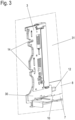
Figur 7 ist der hintere Adapter 4 gezeigt, an dem Mittel 15 zur Fixierung einer Rückwand vorgesehen sind. Im unteren Bereich des Adapters 4 ist ein Fußelement 40 vorgesehen, das aus einem Metallblech gebildet ist und an einer Innenseite des vertikalen Wandabschnittes 8 anliegt. An einer Vorderseite des Fußelementes 40 ist eine Führungslasche 13 integral an dem vertikalen Wandabschnitt 8 ausgebildet, die geneigt ausgebildet ist und deren Ende im Wesentlichen flächenbündig mit einer Oberfläche des Fußelementes 40 ausgerichtet ist, um eine Stufe zwischen dem vertikalen Wandabschnitt 8 und dem Fußelement 40 im Bereich der Führungslasche 13 zu vermeiden. An dem hinteren Adapter 4 ist eine Auflage 42 ausgebildet, die im Wesentlichen flächenbündig mit dem horizontalen Auflagesteg 7 der Trägerschiene 2 ausgerichtet ist und zur Auflage und Befestigung an der Führungsschiene dient. - In
Figur 8 ist der hintere Adapter 4 von einer Außenseite gezeigt, und es ist die Aussparung erkennbar, die durch Prägen der Führungslasche 13 gebildet ist. - In
Figur 9 ist der hintere Adapter 4 bei der Montage eines Bodens 16 gezeigt. Der Boden 16 kann entlang dem vertikalen Wandabschnitt 8 verschoben werden und trifft dann auf die Führungslasche 13, so dass eine Kante des Bodens 16 von dem vertikalen Wandabschnitt 8 wegbewegt wird und der Boden 16 entlang der vertikalen Oberfläche des Fußelementes 40 weiter verschoben werden kann. - In
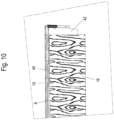
Figur 10 ist der Boden 16 in einer montierten Position in einer Schnittansicht gezeigt, und es ist erkennbar, dass eine Kante des Bodens 16 an dem Fußelement 40 oder daran ausgebildeten Erhebungen anliegt und beabstandet von dem vertikalen Wandabschnitt 8 angeordnet ist. - In
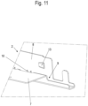
Figur 11 ist der hintere Bereich der Trägerschiene 2 ohne Adapter gezeigt. Die Führungslasche 13 steht von dem vertikalen Wandabschnitt 8 nach innen hervor und kann auch zur Positionierung des hinteren Adapters 4 bei der Montage eingesetzt werden. - In
Figur 12 ist eine Ansicht einer weiteren Ausführungsform der Führungslasche 32 dargestellt. Gezeigt ist der Bereich des vorderen Adapters 3 mit dem Fußelement 30 angelegt an den vertikalen Wandabschnitt 8. Die beiden Ausführungsformen unterscheiden sich dahingehend, dass die Führungslasche 32 nun nicht in den vertikalen Wandabschnitt 8 eingeprägt wurde, stattdessen weist der Adapter 3 bzw. das Fußelement 30 eine integral angeformte Verlängerung auf, die die Führungslasche 32 bildet. Diese wird in Richtung des vertikalen Wandabschnitts 8 gebogen, und taucht in eine Aussparung 17 innerhalb des vertikalen Wandabschnitts 8 ein. Auch diese Form der Gestaltung führt bei der Montage des Bodens 16 zu einer stufenlosen Verschiebung ohne ein Einhaken einer Kante des Bodens 16 an dem Adapter 3 bzw. dem Fußelement 30. - In
Figur 13 ist eine Explosionsdarstellung der Ansicht ausFigur 12 dargestellt. Hier sind besonders vorteilhaft die Ausgestaltung der Führungslasche 32 und die Aussparung 17 zu sehen, Die Führungslasche steht dabei schräg in Richtung des vertikalen Wandabschnittes aus der Ebene des Fußelementes 30 hervor und steht mit dem freien Ende schräg vor einer durch den vertikalen Wandabschnitt 8 gebildeten Ebene hervor. - In
Figur 14 ist eine Rückansicht des vorderen Adapters 3 gezeigt. Hier ist insbesondere der Eingriff der Führungslasche 32 in die Aussparung 17 in dem vertikalen Wandabschnitt 8 zu erkennen. - Analog zur Ausbildung der Führungslasche 32 als Teil des Adapters 3 bzw. des Fußelementes 30 kann die Führungslasche auch als Teil des hinteren Adapters 4 bzw. des hinteren Fußelementes 40 ausgebildet sein.
-
- 1
- Seitenzarge
- 2
- Trägerschiene
- 3
- Adapter
- 4
- Adapter
- 5
- Abdeckung
- 6
- Abdeckung
- 7
- Auflagesteg
- 8
- Wandabschnitt
- 9
- Nut
- 10
- Befestigungselement
- 11
- Rahmenleiste
- 12
- Führungslasche
- 13
- Führungslasche
- 14
- Mittel zur Befestigung einer Frontblende
- 15
- Mittel zur Befestigung einer Rückwand
- 16
- Boden
- 17
- Aussparung
- 30
- Fußelement
- 31
- Rahmenleiste
- 32
- Führungslasche
- 40
- Fußelement
- 41
- Rahmenleiste
- 42
- Auflage
Claims (9)
- Seitenzarge (1) für einen Schubkasten, mit einer Trägerschiene (2), an der ein horizontaler Auflagesteg (7) für einen Boden (16) und ein vertikaler Wandabschnitt (8) ausgebildet ist, wobei an dem vertikalen Wandabschnitt (8) mindestens ein Adapter (3, 4) festgelegt ist, an dem eine Abdeckung (5, 6) und/oder ein Wandelement fixierbar ist, wobei benachbart zu dem mindestens einen Adapter (3, 4) eine Führungslasche (12, 13, 32) an dem vertikalen Wandabschnitt (8) angeordnet ist, die zumindest einen Teil einer Kante des Adapters (3, 4) überdeckt und die Führungslasche (12, 13, 32) an dem vertikalen Wandabschnitt (8) integral ausgebildet ist oder an dem Adapter (3, 4) integral ausgebildet ist und in eine Aussparung (17) in dem vertikalen Wandabschnitt (8) eintaucht, wobei die Führungslasche (12, 13, 32) schräg von einer durch den vertikalen Wandabschnitt (8) gebildeten Ebene hervorsteht und der Boden (16) entlang der Führungslasche (12, 13, 32) bewegt werden kann, so dass eine Kante des Bodens (16) sich von dem vertikalen Wandabschnitt an der Trägerschiene (2) leicht abhebt und in Richtung des Adapters (3, 4) verschoben werden kann, dadurch gekennzeichnet, dass ein Ende der Führungslasche (12, 13) im Wesentlichen flächenbündig mit einer dem Boden (16) zugewandten Oberfläche des Adapters (3, 4) ausgerichtet ist.
- Seitenzarge nach Anspruch 1, dadurch gekennzeichnet, dass die Führungslasche (12, 13, 32) in einem Winkel zwischen 2° und 20° zu der Ebene des vertikalen Wandabschnittes (8) hervorsteht.
- Seitenzarge nach Anspruch 1 oder 2, dadurch gekennzeichnet, dass der mindestens ein Adapter (3, 4) einen vorderer und einen hinterer Adapter (3, 4) umfasst, die an der Trägerschiene (2) festgelegt sind und an jedem der Adapter (3, 4) mindestens eine Führungslasche (12, 13, 32) angeordnet ist.
- Seitenzarge nach einem der vorhergehenden Ansprüche, dadurch gekennzeichnet, dass jeder Adapter (3, 4) ein Metallblech (30, 40) umfasst, das an einer zum Boden (16) gewandten Seite auf dem vertikalen Wandabschnitt (8) aufliegt.
- Seitenzarge nach Anspruch 3, dadurch gekennzeichnet, dass an dem vorderen Adapter (3) Mittel (14) zur Fixierung einer Frontblende vorgesehen sind.
- Seitenzarge nach Anspruch 3 oder 5, dadurch gekennzeichnet, dass an dem hinteren Adapter (4) Mittel (15) zur Fixierung einer Rückwand vorgesehen sind.
- Seitenzarge nach einem der vorhergehenden Ansprüche 1 bis 3, dadurch gekennzeichnet, dass zwischen dem horizontalen Auflagesteg (7) und dem vertikalen Wandabschnitt (8) eine Nut (9) an der Trägerschiene (2) ausgebildet ist.
- Schubkasten mit einer Seitenzarge (1) nach einem der vorhergehenden Ansprüche, an dem ein Boden (16) an der Trägerschiene (2) festgelegt ist.
- Schubkasten nach Anspruch 8, dadurch gekennzeichnet, dass zwischen zwei Adaptern (3, 4) an der Trägerschiene (2) ein Inlay fixiert ist.
Applications Claiming Priority (2)
| Application Number | Priority Date | Filing Date | Title |
|---|---|---|---|
| DE102020103497.0A DE102020103497A1 (de) | 2020-02-11 | 2020-02-11 | Seitenzarge für einen Schubkasten |
| PCT/EP2021/052681 WO2021160512A1 (de) | 2020-02-11 | 2021-02-04 | Seitenzarge für einen schubkasten |
Publications (2)
| Publication Number | Publication Date |
|---|---|
| EP4103014A1 EP4103014A1 (de) | 2022-12-21 |
| EP4103014B1 true EP4103014B1 (de) | 2023-11-01 |
Family
ID=74553834
Family Applications (1)
| Application Number | Title | Priority Date | Filing Date |
|---|---|---|---|
| EP21703448.7A Active EP4103014B1 (de) | 2020-02-11 | 2021-02-04 | Seitenzarge für einen schubkasten |
Country Status (4)
| Country | Link |
|---|---|
| EP (1) | EP4103014B1 (de) |
| CN (1) | CN115003195B (de) |
| DE (1) | DE102020103497A1 (de) |
| WO (1) | WO2021160512A1 (de) |
Family Cites Families (10)
| Publication number | Priority date | Publication date | Assignee | Title |
|---|---|---|---|---|
| MY140411A (en) * | 2006-07-14 | 2009-12-31 | Harn Marketing Sdn Bhd | Drawer fitting |
| JP4737556B2 (ja) * | 2007-04-16 | 2011-08-03 | 繁夫 尾野 | 家具 |
| CN201403824Y (zh) * | 2009-04-08 | 2010-02-17 | 世塑有限公司 | 抽屉面板结合构件 |
| AT509849B1 (de) | 2010-11-16 | 2011-12-15 | Blum Gmbh Julius | Trägerschiene für einen schubladenboden |
| DE102012104457A1 (de) * | 2012-05-23 | 2013-11-28 | Paul Hettich Gmbh & Co. Kg | Fixierungsanordnung und Schubkasten |
| DE202013011426U1 (de) | 2013-12-20 | 2015-03-23 | Grass Gmbh | Schubladenwandeelement |
| DE202013011559U1 (de) * | 2013-12-23 | 2015-03-24 | Grass Gmbh | Dämpfungsvorrichtung |
| DE102015105131B4 (de) * | 2015-04-02 | 2024-06-20 | Paul Hettich Gmbh & Co. Kg | Zarge, insbesondere Seitenzarge, für einen Schubkasten |
| DE102017105798A1 (de) * | 2017-03-17 | 2018-09-20 | Paul Hettich Gmbh & Co. Kg | Zarge für einen Schubkasten |
| CN209554195U (zh) * | 2019-01-31 | 2019-10-29 | 宁波圣瑞思工业自动化有限公司 | 一种导轨转接轨 |
-
2020
- 2020-02-11 DE DE102020103497.0A patent/DE102020103497A1/de active Pending
-
2021
- 2021-02-04 EP EP21703448.7A patent/EP4103014B1/de active Active
- 2021-02-04 WO PCT/EP2021/052681 patent/WO2021160512A1/de not_active Ceased
- 2021-02-04 CN CN202180011332.8A patent/CN115003195B/zh active Active
Also Published As
| Publication number | Publication date |
|---|---|
| CN115003195B (zh) | 2025-07-25 |
| CN115003195A (zh) | 2022-09-02 |
| DE102020103497A1 (de) | 2021-08-12 |
| WO2021160512A1 (de) | 2021-08-19 |
| EP4103014A1 (de) | 2022-12-21 |
Similar Documents
| Publication | Publication Date | Title |
|---|---|---|
| EP2703237B1 (de) | Baugruppe mit einem Regensensor und einer Halteklammer für den Regensensor. | |
| EP1383967B1 (de) | Abdeckung für eine entwässerungseinrichtung | |
| EP2270403B1 (de) | Solartechnischer Kollektor mit Tragschiene | |
| DE102019121404A1 (de) | Schiebetürbeschlag, Möbel und Verfahren zur Montage eines Schiebetürbeschlages | |
| EP0596306A2 (de) | Abdeckleiste für eine in ein Fahrzeugdach eingelassene Rinne | |
| DE8802459U1 (de) | Gehäuse für ein elektrisches Gerät | |
| DE3906682C2 (de) | ||
| EP0917842B1 (de) | Schubkasten | |
| EP0593882A2 (de) | Sockelleiste für den unteren Abschluss von an Bauwerkswänden anbringbaren Wärmedämmschichten | |
| DE19730600A1 (de) | Stulpschienenbeschlag | |
| EP4007096B1 (de) | An einer begrenzungsfläche eines gebäudes festlegbares kabelrinnensystem | |
| EP4103014B1 (de) | Seitenzarge für einen schubkasten | |
| DE29712614U1 (de) | Stulpschienenbeschlag | |
| DE102014111976B4 (de) | Türdichtungssystem | |
| EP3527744B1 (de) | Basisprofil einer fussbodenprofilanordnung | |
| AT500181B1 (de) | Tür- oder fensterbeschlag | |
| DE29803656U1 (de) | Tür- oder Fensterbeschlag | |
| AT17359U1 (de) | Montagehalterung für ein Sandwichelement und System zur Befestigung einer Dachrinne an einem Sandwichelement | |
| EP4411150B1 (de) | Befestigungsklemme | |
| DE4005508C2 (de) | Fassadenverkleidung | |
| EP1584874B1 (de) | Befestigungsvorrichtung für eine Frontplatte | |
| EP0786846B1 (de) | Elektroinstallationskanal | |
| DE9420155U1 (de) | FAssadenbekleidung mit horizontalen Halteprofilen | |
| DE102017207494B4 (de) | Montagevorrichtung und Montageverfahren für Wand- oder Dachtafeln mit wellenartigem oder trapezartigem Querschnitt | |
| DE60012109T2 (de) | Klammer |
Legal Events
| Date | Code | Title | Description |
|---|---|---|---|
| STAA | Information on the status of an ep patent application or granted ep patent |
Free format text: STATUS: UNKNOWN |
|
| STAA | Information on the status of an ep patent application or granted ep patent |
Free format text: STATUS: THE INTERNATIONAL PUBLICATION HAS BEEN MADE |
|
| PUAI | Public reference made under article 153(3) epc to a published international application that has entered the european phase |
Free format text: ORIGINAL CODE: 0009012 |
|
| STAA | Information on the status of an ep patent application or granted ep patent |
Free format text: STATUS: REQUEST FOR EXAMINATION WAS MADE |
|
| 17P | Request for examination filed |
Effective date: 20220812 |
|
| AK | Designated contracting states |
Kind code of ref document: A1 Designated state(s): AL AT BE BG CH CY CZ DE DK EE ES FI FR GB GR HR HU IE IS IT LI LT LU LV MC MK MT NL NO PL PT RO RS SE SI SK SM TR |
|
| DAV | Request for validation of the european patent (deleted) | ||
| DAX | Request for extension of the european patent (deleted) | ||
| GRAP | Despatch of communication of intention to grant a patent |
Free format text: ORIGINAL CODE: EPIDOSNIGR1 |
|
| STAA | Information on the status of an ep patent application or granted ep patent |
Free format text: STATUS: GRANT OF PATENT IS INTENDED |
|
| INTG | Intention to grant announced |
Effective date: 20230621 |
|
| P01 | Opt-out of the competence of the unified patent court (upc) registered |
Effective date: 20230809 |
|
| GRAS | Grant fee paid |
Free format text: ORIGINAL CODE: EPIDOSNIGR3 |
|
| GRAA | (expected) grant |
Free format text: ORIGINAL CODE: 0009210 |
|
| STAA | Information on the status of an ep patent application or granted ep patent |
Free format text: STATUS: THE PATENT HAS BEEN GRANTED |
|
| AK | Designated contracting states |
Kind code of ref document: B1 Designated state(s): AL AT BE BG CH CY CZ DE DK EE ES FI FR GB GR HR HU IE IS IT LI LT LU LV MC MK MT NL NO PL PT RO RS SE SI SK SM TR |
|
| REG | Reference to a national code |
Ref country code: GB Ref legal event code: FG4D Free format text: NOT ENGLISH |
|
| REG | Reference to a national code |
Ref country code: CH Ref legal event code: EP |
|
| REG | Reference to a national code |
Ref country code: DE Ref legal event code: R096 Ref document number: 502021001863 Country of ref document: DE |
|
| REG | Reference to a national code |
Ref country code: IE Ref legal event code: FG4D Free format text: LANGUAGE OF EP DOCUMENT: GERMAN |
|
| REG | Reference to a national code |
Ref country code: LT Ref legal event code: MG9D |
|
| REG | Reference to a national code |
Ref country code: NL Ref legal event code: MP Effective date: 20231101 |
|
| PG25 | Lapsed in a contracting state [announced via postgrant information from national office to epo] |
Ref country code: GR Free format text: LAPSE BECAUSE OF FAILURE TO SUBMIT A TRANSLATION OF THE DESCRIPTION OR TO PAY THE FEE WITHIN THE PRESCRIBED TIME-LIMIT Effective date: 20240202 |
|
| PG25 | Lapsed in a contracting state [announced via postgrant information from national office to epo] |
Ref country code: IS Free format text: LAPSE BECAUSE OF FAILURE TO SUBMIT A TRANSLATION OF THE DESCRIPTION OR TO PAY THE FEE WITHIN THE PRESCRIBED TIME-LIMIT Effective date: 20240301 |
|
| PG25 | Lapsed in a contracting state [announced via postgrant information from national office to epo] |
Ref country code: LT Free format text: LAPSE BECAUSE OF FAILURE TO SUBMIT A TRANSLATION OF THE DESCRIPTION OR TO PAY THE FEE WITHIN THE PRESCRIBED TIME-LIMIT Effective date: 20231101 |
|
| PG25 | Lapsed in a contracting state [announced via postgrant information from national office to epo] |
Ref country code: NL Free format text: LAPSE BECAUSE OF FAILURE TO SUBMIT A TRANSLATION OF THE DESCRIPTION OR TO PAY THE FEE WITHIN THE PRESCRIBED TIME-LIMIT Effective date: 20231101 |
|
| PG25 | Lapsed in a contracting state [announced via postgrant information from national office to epo] |
Ref country code: ES Free format text: LAPSE BECAUSE OF FAILURE TO SUBMIT A TRANSLATION OF THE DESCRIPTION OR TO PAY THE FEE WITHIN THE PRESCRIBED TIME-LIMIT Effective date: 20231101 |
|
| PG25 | Lapsed in a contracting state [announced via postgrant information from national office to epo] |
Ref country code: NL Free format text: LAPSE BECAUSE OF FAILURE TO SUBMIT A TRANSLATION OF THE DESCRIPTION OR TO PAY THE FEE WITHIN THE PRESCRIBED TIME-LIMIT Effective date: 20231101 Ref country code: LT Free format text: LAPSE BECAUSE OF FAILURE TO SUBMIT A TRANSLATION OF THE DESCRIPTION OR TO PAY THE FEE WITHIN THE PRESCRIBED TIME-LIMIT Effective date: 20231101 Ref country code: IS Free format text: LAPSE BECAUSE OF FAILURE TO SUBMIT A TRANSLATION OF THE DESCRIPTION OR TO PAY THE FEE WITHIN THE PRESCRIBED TIME-LIMIT Effective date: 20240301 Ref country code: GR Free format text: LAPSE BECAUSE OF FAILURE TO SUBMIT A TRANSLATION OF THE DESCRIPTION OR TO PAY THE FEE WITHIN THE PRESCRIBED TIME-LIMIT Effective date: 20240202 Ref country code: ES Free format text: LAPSE BECAUSE OF FAILURE TO SUBMIT A TRANSLATION OF THE DESCRIPTION OR TO PAY THE FEE WITHIN THE PRESCRIBED TIME-LIMIT Effective date: 20231101 Ref country code: BG Free format text: LAPSE BECAUSE OF FAILURE TO SUBMIT A TRANSLATION OF THE DESCRIPTION OR TO PAY THE FEE WITHIN THE PRESCRIBED TIME-LIMIT Effective date: 20240201 Ref country code: PT Free format text: LAPSE BECAUSE OF FAILURE TO SUBMIT A TRANSLATION OF THE DESCRIPTION OR TO PAY THE FEE WITHIN THE PRESCRIBED TIME-LIMIT Effective date: 20240301 |
|
| PG25 | Lapsed in a contracting state [announced via postgrant information from national office to epo] |
Ref country code: SE Free format text: LAPSE BECAUSE OF FAILURE TO SUBMIT A TRANSLATION OF THE DESCRIPTION OR TO PAY THE FEE WITHIN THE PRESCRIBED TIME-LIMIT Effective date: 20231101 Ref country code: RS Free format text: LAPSE BECAUSE OF FAILURE TO SUBMIT A TRANSLATION OF THE DESCRIPTION OR TO PAY THE FEE WITHIN THE PRESCRIBED TIME-LIMIT Effective date: 20231101 Ref country code: PL Free format text: LAPSE BECAUSE OF FAILURE TO SUBMIT A TRANSLATION OF THE DESCRIPTION OR TO PAY THE FEE WITHIN THE PRESCRIBED TIME-LIMIT Effective date: 20231101 Ref country code: NO Free format text: LAPSE BECAUSE OF FAILURE TO SUBMIT A TRANSLATION OF THE DESCRIPTION OR TO PAY THE FEE WITHIN THE PRESCRIBED TIME-LIMIT Effective date: 20240201 Ref country code: LV Free format text: LAPSE BECAUSE OF FAILURE TO SUBMIT A TRANSLATION OF THE DESCRIPTION OR TO PAY THE FEE WITHIN THE PRESCRIBED TIME-LIMIT Effective date: 20231101 Ref country code: HR Free format text: LAPSE BECAUSE OF FAILURE TO SUBMIT A TRANSLATION OF THE DESCRIPTION OR TO PAY THE FEE WITHIN THE PRESCRIBED TIME-LIMIT Effective date: 20231101 |
|
| PG25 | Lapsed in a contracting state [announced via postgrant information from national office to epo] |
Ref country code: DK Free format text: LAPSE BECAUSE OF FAILURE TO SUBMIT A TRANSLATION OF THE DESCRIPTION OR TO PAY THE FEE WITHIN THE PRESCRIBED TIME-LIMIT Effective date: 20231101 |
|
| PG25 | Lapsed in a contracting state [announced via postgrant information from national office to epo] |
Ref country code: CZ Free format text: LAPSE BECAUSE OF FAILURE TO SUBMIT A TRANSLATION OF THE DESCRIPTION OR TO PAY THE FEE WITHIN THE PRESCRIBED TIME-LIMIT Effective date: 20231101 |
|
| PG25 | Lapsed in a contracting state [announced via postgrant information from national office to epo] |
Ref country code: SK Free format text: LAPSE BECAUSE OF FAILURE TO SUBMIT A TRANSLATION OF THE DESCRIPTION OR TO PAY THE FEE WITHIN THE PRESCRIBED TIME-LIMIT Effective date: 20231101 |
|
| PG25 | Lapsed in a contracting state [announced via postgrant information from national office to epo] |
Ref country code: SM Free format text: LAPSE BECAUSE OF FAILURE TO SUBMIT A TRANSLATION OF THE DESCRIPTION OR TO PAY THE FEE WITHIN THE PRESCRIBED TIME-LIMIT Effective date: 20231101 Ref country code: SK Free format text: LAPSE BECAUSE OF FAILURE TO SUBMIT A TRANSLATION OF THE DESCRIPTION OR TO PAY THE FEE WITHIN THE PRESCRIBED TIME-LIMIT Effective date: 20231101 Ref country code: EE Free format text: LAPSE BECAUSE OF FAILURE TO SUBMIT A TRANSLATION OF THE DESCRIPTION OR TO PAY THE FEE WITHIN THE PRESCRIBED TIME-LIMIT Effective date: 20231101 Ref country code: DK Free format text: LAPSE BECAUSE OF FAILURE TO SUBMIT A TRANSLATION OF THE DESCRIPTION OR TO PAY THE FEE WITHIN THE PRESCRIBED TIME-LIMIT Effective date: 20231101 Ref country code: CZ Free format text: LAPSE BECAUSE OF FAILURE TO SUBMIT A TRANSLATION OF THE DESCRIPTION OR TO PAY THE FEE WITHIN THE PRESCRIBED TIME-LIMIT Effective date: 20231101 |
|
| REG | Reference to a national code |
Ref country code: DE Ref legal event code: R097 Ref document number: 502021001863 Country of ref document: DE |
|
| PLBE | No opposition filed within time limit |
Free format text: ORIGINAL CODE: 0009261 |
|
| STAA | Information on the status of an ep patent application or granted ep patent |
Free format text: STATUS: NO OPPOSITION FILED WITHIN TIME LIMIT |
|
| PG25 | Lapsed in a contracting state [announced via postgrant information from national office to epo] |
Ref country code: MC Free format text: LAPSE BECAUSE OF FAILURE TO SUBMIT A TRANSLATION OF THE DESCRIPTION OR TO PAY THE FEE WITHIN THE PRESCRIBED TIME-LIMIT Effective date: 20231101 |
|
| REG | Reference to a national code |
Ref country code: CH Ref legal event code: PL |
|
| 26N | No opposition filed |
Effective date: 20240802 |
|
| PG25 | Lapsed in a contracting state [announced via postgrant information from national office to epo] |
Ref country code: LU Free format text: LAPSE BECAUSE OF NON-PAYMENT OF DUE FEES Effective date: 20240204 |
|
| PG25 | Lapsed in a contracting state [announced via postgrant information from national office to epo] |
Ref country code: CH Free format text: LAPSE BECAUSE OF NON-PAYMENT OF DUE FEES Effective date: 20240229 |
|
| PG25 | Lapsed in a contracting state [announced via postgrant information from national office to epo] |
Ref country code: SI Free format text: LAPSE BECAUSE OF FAILURE TO SUBMIT A TRANSLATION OF THE DESCRIPTION OR TO PAY THE FEE WITHIN THE PRESCRIBED TIME-LIMIT Effective date: 20231101 |
|
| PG25 | Lapsed in a contracting state [announced via postgrant information from national office to epo] |
Ref country code: SI Free format text: LAPSE BECAUSE OF FAILURE TO SUBMIT A TRANSLATION OF THE DESCRIPTION OR TO PAY THE FEE WITHIN THE PRESCRIBED TIME-LIMIT Effective date: 20231101 Ref country code: LU Free format text: LAPSE BECAUSE OF NON-PAYMENT OF DUE FEES Effective date: 20240204 Ref country code: CH Free format text: LAPSE BECAUSE OF NON-PAYMENT OF DUE FEES Effective date: 20240229 |
|
| REG | Reference to a national code |
Ref country code: BE Ref legal event code: MM Effective date: 20240229 |
|
| PG25 | Lapsed in a contracting state [announced via postgrant information from national office to epo] |
Ref country code: BE Free format text: LAPSE BECAUSE OF NON-PAYMENT OF DUE FEES Effective date: 20240229 |
|
| PG25 | Lapsed in a contracting state [announced via postgrant information from national office to epo] |
Ref country code: FR Free format text: LAPSE BECAUSE OF NON-PAYMENT OF DUE FEES Effective date: 20240229 |
|
| PG25 | Lapsed in a contracting state [announced via postgrant information from national office to epo] |
Ref country code: IE Free format text: LAPSE BECAUSE OF NON-PAYMENT OF DUE FEES Effective date: 20240204 |
|
| PG25 | Lapsed in a contracting state [announced via postgrant information from national office to epo] |
Ref country code: IE Free format text: LAPSE BECAUSE OF NON-PAYMENT OF DUE FEES Effective date: 20240204 Ref country code: FR Free format text: LAPSE BECAUSE OF NON-PAYMENT OF DUE FEES Effective date: 20240229 Ref country code: BE Free format text: LAPSE BECAUSE OF NON-PAYMENT OF DUE FEES Effective date: 20240229 |
|
| PG25 | Lapsed in a contracting state [announced via postgrant information from national office to epo] |
Ref country code: RO Free format text: LAPSE BECAUSE OF FAILURE TO SUBMIT A TRANSLATION OF THE DESCRIPTION OR TO PAY THE FEE WITHIN THE PRESCRIBED TIME-LIMIT Effective date: 20231101 |
|
| PG25 | Lapsed in a contracting state [announced via postgrant information from national office to epo] |
Ref country code: CY Free format text: LAPSE BECAUSE OF FAILURE TO SUBMIT A TRANSLATION OF THE DESCRIPTION OR TO PAY THE FEE WITHIN THE PRESCRIBED TIME-LIMIT; INVALID AB INITIO Effective date: 20210204 |
|
| PG25 | Lapsed in a contracting state [announced via postgrant information from national office to epo] |
Ref country code: HU Free format text: LAPSE BECAUSE OF FAILURE TO SUBMIT A TRANSLATION OF THE DESCRIPTION OR TO PAY THE FEE WITHIN THE PRESCRIBED TIME-LIMIT; INVALID AB INITIO Effective date: 20210204 |
|
| PG25 | Lapsed in a contracting state [announced via postgrant information from national office to epo] |
Ref country code: FI Free format text: LAPSE BECAUSE OF FAILURE TO SUBMIT A TRANSLATION OF THE DESCRIPTION OR TO PAY THE FEE WITHIN THE PRESCRIBED TIME-LIMIT Effective date: 20231101 |
|
| GBPC | Gb: european patent ceased through non-payment of renewal fee |
Effective date: 20250204 |
|
| PG25 | Lapsed in a contracting state [announced via postgrant information from national office to epo] |
Ref country code: GB Free format text: LAPSE BECAUSE OF NON-PAYMENT OF DUE FEES Effective date: 20250204 |
|
| PGFP | Annual fee paid to national office [announced via postgrant information from national office to epo] |
Ref country code: DE Payment date: 20260217 Year of fee payment: 6 |
|
| PGFP | Annual fee paid to national office [announced via postgrant information from national office to epo] |
Ref country code: AT Payment date: 20260216 Year of fee payment: 6 |
|
| PGFP | Annual fee paid to national office [announced via postgrant information from national office to epo] |
Ref country code: IT Payment date: 20260227 Year of fee payment: 6 |
|
| PGFP | Annual fee paid to national office [announced via postgrant information from national office to epo] |
Ref country code: TR Payment date: 20260129 Year of fee payment: 6 |