EP4103105B1 - System zur implantation eines medizinischen implantats im menschlichen oder tierischen körper - Google Patents
System zur implantation eines medizinischen implantats im menschlichen oder tierischen körper Download PDFInfo
- Publication number
- EP4103105B1 EP4103105B1 EP21712846.1A EP21712846A EP4103105B1 EP 4103105 B1 EP4103105 B1 EP 4103105B1 EP 21712846 A EP21712846 A EP 21712846A EP 4103105 B1 EP4103105 B1 EP 4103105B1
- Authority
- EP
- European Patent Office
- Prior art keywords
- medical implant
- lumen
- wire
- double
- handle
- Prior art date
- Legal status (The legal status is an assumption and is not a legal conclusion. Google has not performed a legal analysis and makes no representation as to the accuracy of the status listed.)
- Active
Links
Images

Classifications
-
- A—HUMAN NECESSITIES
- A61—MEDICAL OR VETERINARY SCIENCE; HYGIENE
- A61B—DIAGNOSIS; SURGERY; IDENTIFICATION
- A61B17/00—Surgical instruments, devices or methods
- A61B17/22—Implements for squeezing-off ulcers or the like on inner organs of the body; Implements for scraping-out cavities of body organs, e.g. bones; for invasive removal or destruction of calculus using mechanical vibrations; for removing obstructions in blood vessels, not otherwise provided for
- A61B17/221—Gripping devices in the form of loops or baskets for gripping calculi or similar types of obstructions
-
- A—HUMAN NECESSITIES
- A61—MEDICAL OR VETERINARY SCIENCE; HYGIENE
- A61F—FILTERS IMPLANTABLE INTO BLOOD VESSELS; PROSTHESES; DEVICES PROVIDING PATENCY TO, OR PREVENTING COLLAPSING OF, TUBULAR STRUCTURES OF THE BODY, e.g. STENTS; ORTHOPAEDIC, NURSING OR CONTRACEPTIVE DEVICES; FOMENTATION; TREATMENT OR PROTECTION OF EYES OR EARS; BANDAGES, DRESSINGS OR ABSORBENT PADS; FIRST-AID KITS
- A61F2/00—Filters implantable into blood vessels; Prostheses, i.e. artificial substitutes or replacements for parts of the body; Appliances for connecting them with the body; Devices providing patency to, or preventing collapsing of, tubular structures of the body, e.g. stents
- A61F2/01—Filters implantable into blood vessels
- A61F2/011—Instruments for their placement or removal
-
- A—HUMAN NECESSITIES
- A61—MEDICAL OR VETERINARY SCIENCE; HYGIENE
- A61B—DIAGNOSIS; SURGERY; IDENTIFICATION
- A61B17/00—Surgical instruments, devices or methods
- A61B17/0057—Implements for plugging an opening in the wall of a hollow or tubular organ, e.g. for sealing a vessel puncture or closing a cardiac septal defect
- A61B2017/00575—Implements for plugging an opening in the wall of a hollow or tubular organ, e.g. for sealing a vessel puncture or closing a cardiac septal defect for closure at remote site, e.g. closing atrial septum defects
- A61B2017/00623—Introducing or retrieving devices therefor
-
- A—HUMAN NECESSITIES
- A61—MEDICAL OR VETERINARY SCIENCE; HYGIENE
- A61B—DIAGNOSIS; SURGERY; IDENTIFICATION
- A61B17/00—Surgical instruments, devices or methods
- A61B2017/00831—Material properties
- A61B2017/00867—Material properties shape memory effect
-
- A—HUMAN NECESSITIES
- A61—MEDICAL OR VETERINARY SCIENCE; HYGIENE
- A61B—DIAGNOSIS; SURGERY; IDENTIFICATION
- A61B17/00—Surgical instruments, devices or methods
- A61B17/12—Surgical instruments, devices or methods for ligaturing or otherwise compressing tubular parts of the body, e.g. blood vessels or umbilical cord
- A61B17/12022—Occluding by internal devices, e.g. balloons or releasable wires
- A61B2017/1205—Introduction devices
- A61B2017/12054—Details concerning the detachment of the occluding device from the introduction device
-
- A—HUMAN NECESSITIES
- A61—MEDICAL OR VETERINARY SCIENCE; HYGIENE
- A61F—FILTERS IMPLANTABLE INTO BLOOD VESSELS; PROSTHESES; DEVICES PROVIDING PATENCY TO, OR PREVENTING COLLAPSING OF, TUBULAR STRUCTURES OF THE BODY, e.g. STENTS; ORTHOPAEDIC, NURSING OR CONTRACEPTIVE DEVICES; FOMENTATION; TREATMENT OR PROTECTION OF EYES OR EARS; BANDAGES, DRESSINGS OR ABSORBENT PADS; FIRST-AID KITS
- A61F2/00—Filters implantable into blood vessels; Prostheses, i.e. artificial substitutes or replacements for parts of the body; Appliances for connecting them with the body; Devices providing patency to, or preventing collapsing of, tubular structures of the body, e.g. stents
- A61F2/95—Instruments specially adapted for placement or removal of stents or stent-grafts
- A61F2002/9505—Instruments specially adapted for placement or removal of stents or stent-grafts having retaining means other than an outer sleeve, e.g. male-female connector between stent and instrument
- A61F2002/9511—Instruments specially adapted for placement or removal of stents or stent-grafts having retaining means other than an outer sleeve, e.g. male-female connector between stent and instrument the retaining means being filaments or wires
Definitions
- the invention relates to a system for implanting a medical implant in the human or animal body.
- a medical implant is an artificial device implanted in the human or animal body, which remains permanently or temporarily within the human or animal body.
- a medical implant is what is known as a stent, which is inserted into hollow organs of the human or animal body in order to keep them open.
- a stent can, for example, be a small, tubular lattice structure made of metal or synthetic fibers.
- stents are used in blood vessels, especially in the coronary arteries, to prevent them from closing again after they have expanded.
- stents in cancer treatment are used to keep constrictions caused by malignant tumors open after they have been dilated.
- VSD ventricular septum defects
- PFO persistent foramen ovale
- PDA persistent ductus arteriosus
- ASD atrial septum defects
- LAA left atrial appendage
- such medical implants are introduced into the human or animal body using a minimally invasive method.
- a minimally invasive procedure access is created to a large blood vessel within the human or animal body, through which a catheter is introduced into the human or animal body. This catheter is guided through the blood vessels to the implantation site. The medical implant is then transported via the catheter using an insertion aid.
- the medical implants usually consist of a shape-memory material, so that the medical implant unfolds into a predetermined shape after leaving the catheter.
- the medical implant is thus transported to the implantation site by means of the insertion aid and via the catheter unfolds into the predetermined shape after leaving the catheter. After the medical implant has been inserted correctly at the implantation site in the human or animal body, the connection between the insertion aid and the medical implant can be released.
- the medical implant must be connected as firmly as possible to the insertion aid during transport through the catheter and at the same time be able to be easily detached from the insertion aid after implantation has taken place. It is known from the prior art, for example, to clamp the medical implant onto a carrier wire of the insertion aid and to release the clamping connection after successful implantation of the medical implant.
- the disadvantage of such a connection between the medical implant and the insertion aid is that a relatively high force is required to loosen the connection between the implant and the carrier wire, and the connection to the medical implant and the carrier wire, which is based on a frictional force, can also be negatively influenced by liquids, for example, so that the connection between the medical implant and the carrier wire can loosen prematurely.
- the WO 2015/078807 A1 discloses a system for connecting a medical implant to an insertion aid, wherein the medical implant and the insertion aid each have a spiral-shaped connection region, which engage in one another in the connected state and are fixed relative to one another by a locking wire.
- this requires a specially designed helical connection area on the medical implant.
- the US 2010/0268201 A1 discloses another system for implanting a medical implant.
- the invention is therefore based on the object of providing a system for implanting a medical implant in the human or animal body, which ensures a secure connection between the medical implant and the insertion aid during the implantation of the medical implant in the human or animal body and at the same time enables the connection between the medical implant and the insertion aid to be easily released after the medical implant has been implanted.
- the connection between the medical implant and the insertion aid should have the smallest possible diameter due to its use in minimally invasive surgery. preferably a diameter that is smaller than or equal to the diameter of the medical implant or the insertion aid.
- the wire-like element is guided through a connection device such as a loop or eyelet of the medical implant in order to create a detachable connection between the system according to the invention and the medical implant.
- a first end of the wire-like element is subsequently passed through the first lumen of the double lumen guide tube and the second end of the wire-like element is passed through the second lumen of the double lumen guide tube.
- one end of the wire-like member is fixed to the handle while the other end of the wire-like member is releasably connected to the handle.
- the medical implant can be implanted via a catheter that has already been placed at the implantation site in the human or animal body.
- the connection between the system according to the invention and the medical implant is released, so that the medical implant remains in the human or animal body and the system according to the invention can be removed again.
- the detachable connection between the handle and one end of the wire-like element is released.
- the wire-like element is pulled out of the loop or eyelet of the medical implant at the same time, as a result of which the connection between the system according to the invention and the medical implant is released. After releasing this connection, the double-lumen tube can be removed from the human or animal body.
- the proximal end of the double-lumen guide tube within the meaning of the invention is the end facing the human or animal body and the distal end of the double-lumen guide tube within the meaning of the invention is the end facing away from the human body.
- connection between the system according to the invention and the medical implant has a very small diameter, since only the wire-like element has to be guided through an eyelet or loop of the medical implant. No additional locking wire or the like is required, and no specially formed connecting sections on the medical implant and/or the insertion aid are disclosed, as is disclosed in the prior art. The diameter of the catheter required for implantation can thus be reduced.
- the double-lumen guide tube prevents the wire-like element from twisting into one another, which would make removing and thus releasing the medical implant significantly more difficult. Only one section of the wire-like element is passed through each lumen of the double-lumen guide tube.
- the system according to the invention comprises a very small number of components, which at the same time have the simplest possible structure.
- the system according to the invention can be produced simply and inexpensively. Storage, packaging and transport costs are also reduced. Handling is also very simple and intuitive and the user does not need to have any special knowledge to use it.
- the wire-like element consists of a metal, in particular stainless steel.
- a wire-like element made of metal has a high tensile strength with a small diameter, as a result of which the diameter of the system according to the invention can be minimized. This has a positive effect on the implantation, especially since a catheter with a smaller diameter can be used for the implantation.
- the wire-like element has a diameter of 0.1 mm to 0.5 mm, in particular a diameter of 0.2 mm.
- the double-lumen guide hose consists at least partially of a plastic.
- the double-lumen guide tube is flexible, which simplifies guiding the guide tube through the vascular system of the human or animal body.
- a flexible guide tube for example, adapts to the shape of a catheter that has already been placed.
- the mechanical properties of the double-lumen guide tube can also be adjusted by reinforcing elements such as metal elements integrated in the plastic, in particular wires or metal grids.
- the guide hose can also be designed to be controllable by means of wires introduced into the plastic.
- the double-lumen guide tube has a diameter of 1.0 mm to 2.0 mm, in particular a diameter of 1.76 mm.
- the individual lumens of the double-lumen guide tube have an inner diameter that is adapted to the diameter of the wire-like element, so that the wire-like element can be guided through the lumen of the double-lumen guide tube.
- the diameter of the lumen is at least slightly larger than the diameter of the wire-like element.
- the double-lumen guide tube comprises two inner tube-like elements which form the first lumen and the second lumen of the double-lumen guide tube.
- the double-lumen guide tube thus consists of a total of three tube-like elements, two tube-like elements being arranged in an outer tube-like element are.
- the two inner tube-like elements form the first lumen and the second lumen of the double-lumen guide tube.
- the invention is also not limited to a double-lumen guide tube, but can also be implemented with a multi-lumen tube. However, only two lumens are required to guide the wire-like element. Any additional lumens may be used for other purposes, such as injecting liquids such as contrast media for imaging, or injecting or inserting other liquids, objects and/or equipment.
- the two inner hose-like elements are each designed as stainless steel coils.
- Such stainless steel coils have a high degree of radial flexibility while at the same time being stable in the longitudinal direction.
- connection device of the medical implant is designed as an eyelet or loop.
- Such an eyelet or loop can be easily produced on the medical implant, since medical implants are often made from wire-like elements.
- the only thing that needs to be formed from the wire-like element of the medical implant is an eyelet or loop, for example at one end of the medical implant.
- the first end of the wire-like element comprises a nipple which can be fixed in a corresponding recess of the handle.
- the first end of the wire-like element can be easily fixed to the handle.
- fixations are also possible, such as gluing, welding, soldering and the like.
- the handle comprises a clamping mechanism for the second end of the wire-like element for releasably fixing the second end of the wire-like element on the handle.
- the clamping mechanism allows the second end to be releasably fixed to the handle.
- the clamping connection is released and the connection between the system according to the invention and the medical implant can be released by pulling the wire-like element out of the eyelet or loop of the medical implant to be solved. This is achieved in that the first end of the wire-like element is fixed to the handle and the connection to the second end of the wire-like element is released and the wire-like element is pulled by means of the handle.
- the clamping mechanism includes a safeguard against unintentional actuation of the clamping mechanism, in particular against unintentional loosening of the clamping mechanism.
- the fuse must therefore be released before the clamping mechanism is actuated.
- the system according to the invention comprises an implantation catheter for guiding the double-lumen guide hose and the medical implant connected thereto to the implantation site in the human or animal body.
- the implantation catheter is guided through the vascular system of the human or animal body to the implantation site.
- access to a larger vessel of the human or animal body is established, in particular in the groin area of the human body.
- a steerable catheter can be steered through the vasculature to the site of implantation in the human or animal body.
- the implantation catheter is guided to the implantation site using a guide wire that has already been placed.
- the medical implant is advanced through the implantation catheter by means of the double-lumen guide tube via the implantation catheter.
- the double-lumen guide tube assumes the function of a so-called pusher, which pushes the medical implant through the implantation catheter to the implantation site.
- the connection of the system according to the invention to the medical implant is released as described above and the double-lumen guide tube and the implantation catheter can be removed from the human or animal body.
- the system also includes a Y-connector for flushing the system, in particular the double-lumen guide tube and/or the implantation catheter.
- the system also includes a so-called pusher in order to move the double-lumen guide tube and the medical implant connected to it through the implantation catheter.
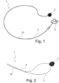
- FIG 1 shows an exemplary embodiment of a system 1 according to the invention for implanting a medical implant 2 in the human or animal body.
- the system 1 comprises a wire-like element 3 for connecting the system 1 to the medical implant 2.
- the system 1 also comprises a double-lumen guide tube 4 for the wire-like element 3 and a handle 5 for handling the system 1.
- the medical implant 2 is arranged at the proximal end of the guide tube 4 and the handle 5 at the distal end of the guide tube 4, with the end of the guide tube 4 facing the human or animal body being proximal and the end of the guide tube 4 facing away from the human or animal body being distal.
- the wire-like element 3 is fixed to the handle 5 with a first end 9, guided through a first lumen 6 of the double-lumen guide tube 4 to the medical implant 2, then engages with a connecting device 8 of the medical implant 2 and is then guided through a second lumen 7 of the double-lumen guide tube 4 to the handle 5.
- the second end 10 of the wire-like element 3 is detachably fixed to the handle 5 .
- the system 1 also comprises an implantation catheter 15, by means of which the medical implant 2 is advanced to the implantation site in the human or animal body by means of the double-lumen guide tube 4.
- the wire-like element 3 consists, for example, of a metal, in particular high-grade steel, and has a diameter of 0.1 mm to 0.5 mm, in particular 0.2 mm.
- the double-lumen guide tube 4 consists, for example, at least partially of a plastic and has a diameter of 1.0 mm to 2.0 mm, in particular 1.76 mm.
- connection device 8 of the medical implant 2 is preferably designed as an eyelet or loop.
- a so-called pusher is arranged between the implantation catheter 15 and the handle 5 in order to move the double-lumen guide tube 4 and the medical implant 2 fastened therein through the implantation catheter 15 .
- a Y-connector can be arranged at the transition between the implantation catheter 15 and the double-lumen guide tube 4 for rinsing the system 1 according to the invention, in particular the implantation catheter 15.
- FIG 2 shows a detailed view of the connection of the system 1 according to the invention to a medical implant 2 at the proximal end of the system 1.
- the double-lumen guide tube 4 with the medical implant 2 attached thereto emerges from the implantation catheter 15.
- the medical implant 2 is connected to the system 1 according to the invention by the wire-like element 3, with the wire-like element 2 engaging in a connecting device 8 of the medical implant.
- the connection device 8 of the medical implant is designed, for example, as an eyelet or loop.
- the two ends 9 , 10 of the wire-like element are guided through the first lumen 6 and the second lumen 7 of the double-lumen guide tube 4 .
- FIG 3 is a detailed view of a handle 5 of a system 1 according to the invention for implanting a medical implant 2 in the human or animal body.
- a first end 9 of the wire-like element 4 is firmly fixed to the handle 5 .
- the wire-like 4 has, for example, a nipple 12 on the first one, which engages in a corresponding recess 13 on the handle 5 .
- fixations such as gluing, welding, or soldering other connection techniques.
- the second end 10 of the wire-like element 4 is detachably connected to the handle 5 by means of a clamping mechanism 14 .
- connection between the second end 10 of the wire-like element 4 and the handle 5 is released and the wire-like element 4 is pulled out of the connection device 8 of the medical implant 2 in order to release the connection between the system 1 according to the invention and the medical implant 2.
- the clamping mechanism 14 includes a safety device (not shown) which prevents the clamping mechanism 14 from being operated unintentionally.
- the fuse is designed as a bolt, for example.
- FIG. 4 a detailed view of a medical implant 2 connected to a system 1 according to the invention is shown.
- the double-lumen guide tube 4 emerges from the implantation catheter 15 .
- the wire-like element 3 is guided from the handle 5 of the system 1 according to the invention to the medical implant 2 through the first lumen 6 of the double-lumen guide tube 4 .
- the wire-like element 3 engages in the connection device 8 of the medical implant 2 and is guided through the second lumen 7 back to the handle 5 of the system 1 according to the invention.
- a first end 9 of the wire-like element 3 is fixed to the handle 5 , while the second end 10 is detachably attached to the handle 5 .
- the detachable connection between the handle 5 and the second end 10 of the wire-like element 3 is released and the wire-like element is pulled out of the double-lumen guide tube 4 by means of the handle 5 and the first end 9 fixed thereto until the wire-like element 3 no longer engages in the connecting device 8 of the medical implant 2.
- the double-lumen guide tube 4 can then be pulled out of the implantation catheter 15 and finally the implantation catheter 15 is removed from the human or animal body.
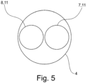
- FIG 5 shows a cross-sectional view of a double-lumen guide tube 4 of a system 1 according to the invention figure 5
- the double-lumen guide tube 4 comprises two inner tube-like elements 11 which form the first lumen 6 and the second lumen 7 of the double-lumen guide tube 4 .
- the two inner ones tube-like elements 11 are each formed, for example, as a stainless steel coil.
Landscapes
- Health & Medical Sciences (AREA)
- Life Sciences & Earth Sciences (AREA)
- Surgery (AREA)
- Biomedical Technology (AREA)
- Public Health (AREA)
- Engineering & Computer Science (AREA)
- Heart & Thoracic Surgery (AREA)
- Vascular Medicine (AREA)
- Veterinary Medicine (AREA)
- Animal Behavior & Ethology (AREA)
- General Health & Medical Sciences (AREA)
- Medical Informatics (AREA)
- Orthopedic Medicine & Surgery (AREA)
- Nuclear Medicine, Radiotherapy & Molecular Imaging (AREA)
- Molecular Biology (AREA)
- Oral & Maxillofacial Surgery (AREA)
- Cardiology (AREA)
- Transplantation (AREA)
- Media Introduction/Drainage Providing Device (AREA)
- Prostheses (AREA)
- Steroid Compounds (AREA)
Description
- Die Erfindung betrifft ein System zur Implantation eines medizinischen Implantats im menschlichen oder tierischen Körper. Ein medizinisches Implantat ist eine im menschlichen oder tierischen Körper eingepflanzte, künstliche Vorrichtung, welche permanent oder temporär innerhalb des menschlichen oder tierischen Körpers verbleibt.
- Ein Beispiel für ein medizinisches Implantat ist ein sogenannter Stent, welcher in Hohlorgane des menschlichen oder tierischen Körpers eingebracht wird, um diese offen zu halten. Bei einem Stent kann es sich beispielsweise um ein kleines Gittergerüst in Röhrenform aus Metall oder Kunstfasern handeln. Verwendung finden Stents zum einen in Blutgefäßen, speziell in den Herzkranzgefäßen, um nach deren Aufdehnung einen erneuten Verschluss zu verhindern. Zum anderen dienen Stents in der Krebsbehandlung dazu, durch bösartige Tumore verursachte Verengungen nach einer Aufdehnung offen zu halten.
- Weiterhin finden medizinische Implantate in der Herzchirurgie Anwendung, wobei die medizinischen Implantate meist dazu dienen, eine abnormale Öffnung innerhalb des Herzens zu verschließen. Beispiele für derartige Anwendungen sind die Behandlung von Ventrikel Septum Defekten (VSD), Persistierenden Foramen Ovale (PFO), Persistierender Ductus Arteriosus (PDA), Atrium Septum Defekten (ASD) oder der Verschluss des linken Herzohrs (Left Atrial Appendage, LAA).
- Soweit möglich werden derartige medizinische Implantate mittels eines minimalinvasiven Verfahrens in den menschlichen oder tierischen Körper eingebracht. Bei einem minimalinvasiven Verfahren wird ein Zugang zu einem großen Blutgefäß innerhalb des menschlichen oder tierischen Körpers geschaffen, über welchen ein Katheter in den menschlichen oder tierischen Körper eingeführt wird. Über die Blutgefäße wird dieser Katheter zur Implantationsstelle geführt. Nachfolgend wir über den Katheter das medizinische Implantat mittels einer Einführhilfe transportiert.
- Üblicherweise bestehen die medizinischen Implantate aus einem Formgedächtnismaterial, so dass sich das medizinische Implantat nach Verlassen des Katheters in eine vorgegebene Form entfaltet. Das medizinische Implantat wird also mittels der Einführhilfe über den Katheter zu der Implantationsstelle transportiert und entfaltet sich nach Verlassen des Katheters in die vorgegebene Form. Nachdem das medizinische Implantat korrekt an der Implantationsstelle in den menschlichen oder tierischen Körper eingesetzt wurde, kann die Verbindung zwischen Einführhilfe und medizinischen Implantat gelöst werden.
- Folglich muss das medizinische Implantat während des Transports durch den Katheter möglichst fest mit der Einführhilfe verbunden sein und sich gleichzeitig nach erfolgter Implantation einfach von der Einführhilfe lösen lassen. Aus dem Stand der Technik ist es beispielsweise bekannt, das medizinische Implantat auf einen Trägerdraht der Einführhilfe aufzuklemmen und die Klemmverbindung nach erfolgreicher Implantation des medizinischen Implantats zu lösen. Nachteilig an einer derartigen Verbindung zwischen dem medizinischen Implantat und der Einführhilfe ist jedoch, dass zum Lösen der Verbindung zwischen Implantat und Trägerdraht eine relativ hohe Kraft notwendig ist und weiterhin kann die Verbindung zum medizinischen Implantat und Trägerdraht, welcher auf einer Reibkraft basiert, beispielsweise durch Flüssigkeiten negativ beeinflusst werden, so dass sich die Verbindung zwischen medizinischen Implantat und Trägerdraht frühzeitig lösen kann.
- Die
WO 2015/078807 A1 offenbart ein System zum Verbinden eines medizinischen Implantats mit einer Einführhilfe, wobei das medizinische Implantat und die Einführhilfe jeweils einen spiralförmigen Verbindungsbereich aufweisen, welche im verbundenen zustand ineinandergreifen und durch einen Riegeldraht miteinander relativ zueinander fixiert sind. Dies setzt jedoch einen speziell ausgestalteten spiralförmigen Verbindungsbereich am medizinischen Implantat voraus. - Die
US 2010/0268201 A1 offenbart ein weiteres System zum Implantieren eines medizinischen Implantats. - Der Erfindung liegt somit die Aufgabe zugrunde, ein System zur Implantation eines medizinischen Implantats im menschlichen oder tierischen Körper bereitzustellen, welches während der Implantation des medizinischen Implantats im menschlichen oder tierischen Körper eine sichere Verbindung zwischen medizinischen Implantat und Einführhilfe gewährleistet und gleichzeitig ein einfaches Lösen der Verbindung zwischen medizinischen Implantat und Einführhilfe nach erfolgter Implantation des medizinischen Implantats ermöglicht. Ferner sollte die Verbindung zwischen dem medizinischen Implantat und der Einführhilfe aufgrund eines Einsatzes in der minimalinvasiven Chirurgie einen möglichst geringen Durchmesser aufweisen, vorzugsweise einen Durchmesser der kleiner oder gleich dem Durchmesser des medizinischen Implantats bzw. der Einführhilfe ist.
- Die Aufgabe wird erfindungsgemäß gelöst durch ein System zur Implantation eines medizinischen Implantats im menschlichen oder tierischen Körper, umfassend:
- ein drahtartiges Element zur Verbindung des Systems mit dem medizinischen Implantat,
- einen doppellumigen Führungsschlauch für das drahtartige Element, und
- einen Handgriff zur Handhabung des Systems,
- wobei das medizinische Implantat am proximalen Ende des Führungsschlauchs angeordnet ist und der Handgriff am distalen Ende des Führungsschlauchs, und wobei das drahtartige Element mit einem ersten Ende am Handgriff fixiert ist, durch ein erstes Lumen des doppellumigen Führungsschlauchs zu dem medizinischen Implantat geführt ist, mit einer Verbindungseinrichtung des medizinischen Implantat eingreift und durch ein zweites Lumen des doppellumigen Führungsschlauchs zum Handgriff geführt ist und am Handgriff mit einem zweiten Ende lösbar fixiert ist.
- Bei der Herstellung des erfindungsgemäßen Systems wird beispielsweise das drahtartige Element durch eine Verbindungseinrichtung wie eine Schlaufe oder Öse des medizinischen Implantats geführt, um eine lösbare Verbindung zwischen dem erfindungsgemäßen System und dem medizinischen Implantat herzustellen. Ein erstes Ende des drahtartigen Elements wird nachfolgend durch das erste Lumen des doppellumigen Führungsschlauchs geführt und das zweite Ende des drahtartigen Elements wird durch das zweite Lumen des doppellumigen Führungsschlauchs geführt. Dadurch wird das medizinische Implantat am proximalen Ende des doppellumigen Führungsschlauchs fixiert. Am distalen Ende des doppellumigen Führungsschlauchs wird ein Ende des drahtartigen Elements an dem Handgriff fixiert, während das andere Ende des drahtartigen Elements lösbar mit dem Handgriff verbunden wird. Mittels des so hergestellten Systems kann das medizinische Implantat über einen bereits zur Implantationsstelle im menschlichen oder tierischen Körper gelegten Katheter implantiert werden. Nachdem das medizinische Implantat korrekt im menschlichen Körper positioniert wurde, was beispielsweise mittels eines bildgebenden Verfahrens überprüft wird, wird die Verbindung zwischen dem erfindungsgemäßen System und dem medizinischen Implantat gelöst, so dass das medizinische Implantat im menschlichen oder tierischen Körper verbleibt und das erfindungsgemäße System wieder entfernt werden kann. Dazu wird die lösbare Verbindung zwischen Handgriff und einem Ende es drahtartigen Elements gelöst. Durch Ziehen an dem Handgriff wird das drahtartige Element durch die Fixierung des anderen Endes des drahtartigen Elements an dem Handgriff aus dem menschlichen oder tierischen Körper gezogen. Dadurch wird gleichzeitig das drahtartige aus der Schlaufe oder Öse des medizinischen Implantats gezogen, wodurch die Verbindung zwischen dem erfindungsgemäßen System und dem medizinischen Implantat gelöst wird. Nach dem Lösen dieser Verbindung kann der doppellumige Schlauch aus dem menschlichen oder tierischen Körper entfernt werden.
- Das proximale Ende des doppellumigen Führungsschlauchs im Sinne der Erfindung ist das dem menschlichen oder tierischen Körper zugewandte Ende und das distale Ende des doppellumigen Führungsschlauchs im Sinne der Erfindung ist das dem menschlichen Körper abgewandte Ende.
- Die Verbindung zwischen dem erfindungsgemäßen System und dem medizinischen Implantat weist einen sehr geringen Durchmesser auf, da lediglich das drahtartige Element durch eine öse oder Schlaufe des medizinischen Implantats geführt werden muss. Es wird kein zusätzlicher Riegeldraht oder ähnliches benötigt und auch keine speziell ausgeformten Verbindungsabschnitte am medizinischen Implantat und/oder der Einführhilfe wie im Stand der Technik offenbart. Somit kann der für die Implantation benötigte Durchmesser des Katheters reduziert werden.
- Der doppellumige Führungsschlauch verhindert dabei, dass sich das drahtartige Element ineinander verdreht, wodurch das Entfernen und somit Lösen des medizinischen Implantats deutlich erschwert würde. Durch jedes Lumen des doppellumigen Führungsschlauch ist jeweils nur ein Abschnitt des drahtartigen Elements geführt.
- Das erfindungsgemäße System umfasst eine sehr geringe Anzahl von Komponenten, welche gleichzeitig einen möglichst einfachen Aufbau haben. Dadurch lässt sich das erfindungsgemäße System einfach und kostengünstig herstellen. Ferner verringern sich Lager-, Verpackungs- und Transportkosten. Auch ist die Handhabung sehr einfach und intuitiv und der Anwender muss keine besonderen Kenntnisse für die Nutzung haben.
- Gemäß einer vorteilhaften Variante der Erfindung besteht das drahtartige Element aus einem Metall, insbesondere aus Edelstahl. Ein drahtartiges Element aus Metall weist eine hohe Zugfestigkeit bei einem geringen Durchmesser auf, wodurch der Durchmesser des erfindungsgemäßen Systems minimiert werden kann. Dies wirkt sich Positiv auf die Implantation aus, insbesondere da ein Katheter mit einem geringeren Durchmesser für die Implantation benutzt werden kann.
- Nach einer zweckmäßigen Variante der Erfindung weist das drahtartige Element einen Durchmesser von 0,1 mm bis 0,5 mm auf, insbesondere einen Durchmesser von 0,2 mm.
- In einer bevorzugten Variante der Erfindung besteht der doppellumige Führungsschlauch zumindest teilwiese aus einem Kunststoff. Dadurch ist der doppellumige Führungsschlauch flexibel, was die Führung des Führungsschlauchs durch das Gefäßsystem des menschlichen oder tierischen Körpers vereinfacht. Ein flexibel Führungsschlauchs passt sich beispielsweise der Form eines bereits gelegten Katheters an. Die mechanischen Eigenschaften des doppellumigen Führungsschlauchs können ferner durch Verstärkungselemente wie in dem Kunststoff integrierte Metallelement, insbesondere Drähte oder Metallgitter, angepasst werden. Auch kann der Führungsschlauch durch in den Kunststoff eingebrachte Drähte steuerbar ausgebildet werden.
- Nach einer zweckmäßigen Variante der Erfindung weist der doppellumige Führungsschlauch einen Durchmesser von 1,0 mm bis 2,0 mm auf, insbesondere einen Durchmesser von 1,76 mm.
- Die einzelnen Lumen des doppellumigen Führungsschlauch weisen einen an den Durchmesser des drahtartigen Elements angepassten Innendurchmesser auf, so dass das drahtartige Element durch die Lumen des doppellumigen Führungsschlauchs geführt werden kann. Insbesondere ist der Durchmesser der Lumen wenigstens geringfügig größer als der Durchmesser des drahtartigen Elements.
- Gemäß einer Variante der Erfindung umfasst der doppellumige Führungsschlauch zwei innenliegende schlauchartige Elemente, welche das erste Lumen und das zweite Lumen des doppellumigen Führungsschlauchs bilden. Der doppellumige Führungsschlauch besteht also aus insgesamt drei schlauchartigen Elementen, wobei zwei schlauchartige Elemente in einem äußeren schlauchartigen Element angeordnet sind. Die zwei innenliegenden schlauchartigen Elemente bilden dabei das erste Lumen und das zweite Lumen des doppellumigen Führungsschlauchs.
- Die Erfindung ist auch nicht auf einen doppellumigen Führungsschlauch begrenzt, sondern kann auch mit einem mehrlumigen Schlauch verwirklicht werden. Für die Führung des drahtartigen Elements werden jedoch nur zwei Lumen benötigt. Eventuell weitere Lumen können für andere Zwecke genutzt werden, wie beispielsweise Injektion von Flüssigkeiten wie Kontrastmittel für bildgebende Verfahren oder das Injizieren oder Einführen anderer Flüssigkeiten, Gegenstände und/oder Gerätschaften.
- In einer zweckmäßigen Variante der Erfindung sind die zwei innenliegenden schlauchartige Elemente jeweils als Edelstahlwende ausgebildet. Derartige Edelstahlwendel weisen eine hohe radiale Flexibilität auf, bei einer gleichzeitigen Stabilität in Längsrichtung.
- Nach einer vorteilhaften Variante der Erfindung ist die Verbindungseinrichtung des medizinischen Implantats als Öse oder Schlaufe ausgebildet. Eine derartige Öse oder Schlaufe lässt sich einfach an dem medizinischen Implantat herstellen, da medizinische Implantate häufig aus drahtartigen Elementen hergestellt werden. Es muss als nur aus dem drahtartigen Element des medizinischen Implantats eine Öse oder Schlaufe geformt werden, beispielsweise an einem Ende des medizinischen Implantats.
- Gemäß einer weiteren Variante der Erfindung umfasst das erste Ende des drahtartigen Elements einen Nippel, welcher in einer entsprechenden Ausnehmung des Handgriffs fixierbar ist. Dadurch lässt sich das erste Ende des drahtartigen Elements einfach am Handgriff fixieren. Es sind aber auch andere Fixierungen möglich, wie Kleben, Schweißen, Löten und dergleichen.
- Erfindungsgemäß umfasst der Handgriff einen Klemmmechanismus für das zweite Ende des drahtartigen Elements, zur lösbaren Fixierung des zweiten Endes des drahtartigen Elements am Handgriff. Durch den Klemmmechanismus lässt sich das zweite Ende lösbar am Handgriff fixieren. Nach erfolgreicher Implantation des medizinischen Implantats wird die Klemmverbindung gelöst und die Verbindung zwischen dem erfindungsgemäßen System und dem medizinischen Implantat kann durch Herauszeihen des drahtartigen Elements aus der Öse oder Schlaufe des medizinischen Implantats gelöst werden. Dies wird dadurch erreicht, dass das erste Ende des drahtartigen Elements am Handgriff fixiert ist und die Verbindung zum zweiten Ende des drahtartigen Elements gelöst wird und das drahtartige Element mittels des Handgriffs gezogen wird.
- Nach der Erfindung umfasst der Klemmmechanismus eine Sicherung gegen ein unbeabsichtigtes Betätigen des Klemmmechanismus, insbesondere gegen ein unbeabsichtigtes Lösen des Klemmmechanismus. Es muss also vor einer Betätigung des Klemmmechanismus die Sicherung gelöst werden.
- Gemäß einer weiteren zweckmäßigen Variante der Erfindung umfasst das erfindungsgemäße System einen Implantationskatheter zur Führung des doppellumigen Führungsschlauchs und des damit verbundenen medizinischen Implantats zur Implantationsstelle im menschlichen oder tierischen Körper. Der Implantationskatheter wird durch das Gefäßsystem des menschlichen oder tierischen Körpers zur Implantationsstelle geführt. Dazu wird beispielsweis ein Zugang zu einem größeren Gefäß des menschlichen oder tierischen Körpers hergestellt, insbesondere in der Leistengegend des menschlichen Körpers. Ein steuerbarer Katheter kann durch das Gefäßsystem zur Implantationsstelle im menschlichen oder tierischen Körper gelenkt werden. Alternativ wird der Implantationskatheter mittels eines bereits gelegten Führungsdrahts zur Implantationsstelle geführt. Über den Implantationskatheter wird das medizinische Implantat mittels des doppellumigen Führungsschlauchs durch den Implantationskatheter vorgeschoben. Der doppellumige Führungsschlauch übernimmt dabei die Funktion eines sogenannten Pushers, welcher das medizinische Implantat durch den Implantationskatheter zur Implantationsstelle vorschiebt. Nach erfolgreicher Implantation wird die Verbindung des erfindungsgemäßen Systems zum medizinischen Implantat wie vorbeschrieben gelöst und der doppellumige Führungsschlauch und der Implantationskatheter können aus dem menschlichen oder tierischen Körper entfernt werden.
- In einer Variante der Erfindung umfasst das System zusätzlich einen Y-Konnektor zum Spülen des Systems, insbesondere des doppellumigen Führungsschlauchs und/oder des Implantationskatheters.
- Nach einer weiteren Variante umfasst das System ferner einen sogenannten Pusher, um den doppellumigen Führungsschlauch und das damit verbundene medizinische Implantat durch den Implantationskatheter zu bewegen.
- Nachfolgend wird die Erfindung anhand der in den Figuren dargestellten Ausführungsbeispiele näher erläutert. Es zeigen:
- Fig. 1
- eine Ansicht eines erfindungsgemäßen Systems,
- Fig. 2
- eine Detailansicht des proximalen Endes des Systems aus
Figur 1 , - Fig. 3
- eine Detailansicht eines Handgriffs eines erfindungsgemäßen Systems,
- Fig. 4
- eine Detailansicht eines mit einem erfindungsgemäßen System verbundenen medizinischen Implantats, und
- Fig. 5
- eine Querschnittsansicht eines doppellumigen Führungsschlauchs eines erfindungsgemäßen Systems.
-
Figur 1 zeigt eine beispielhafte Ausführungsform eines erfindungsgemäßen Systems 1 zur Implantation eines medizinischen Implantats 2 im menschlichen oder tierischen Körper. Das System 1 umfasst ein drahtartiges Element 3 zur Verbindung des Systems 1 mit dem medizinischen Implantat 2. Das System 1 umfasst ferner einen doppellumigen Führungsschlauch 4 für das drahtartige Element 3 und einen Handgriff 5 zur Handhabung des Systems 1. - Das medizinische Implantat 2 ist am proximalen Ende des Führungsschlauchs 4 angeordnet und der Handgriff 5 am distalen Ende des Führungsschlauch 4, wobei proximal das dem menschlichen oder tierischen Körper zugewandte Ende des Führungsschlauchs 4 betrifft und distal das dem menschlichen oder tierischen Körper abgewandte Ende des Führungsschlauchs 4.
- Das drahtartige Element 3 ist mit einem ersten Ende 9 am Handgriff 5 fixiert ist, durch ein erstes Lumen 6 des doppellumigen Führungsschlauchs 4 zu dem medizinischen Implantat 2 geführt, greift nachfolgend mit einer Verbindungseinrichtung 8 des medizinischen Implantats 2 ein und ist anschließend durch ein zweites Lumen 7 des doppellumigen Führungsschlauchs 4 zum Handgriff 5 geführt. Am Handgriff 5 ist das zweite Ende 10 des drahtartigen Elements 3 lösbar fixiert.
- Gemäß dem Ausführungsbeispiel aus
Fig. 1 umfasst das erfindungsgemäße System 1 ferner einen Implantationskatheter 15, mittels welchem das medizinische Implantat 2 mittels des doppellumigen Führungsschlauchs 4 zur Implantationsstelle im menschlichen oder tierischen Körper vorgeschoben wird. - Das drahtartige Element 3 besteht beispielsweise aus einem Metall, insbesondere Edelstahl und weist einen Durchmesser von 0,1 mm bis 0,5 mm, insbesondere 0,2 mm, auf.
- Der doppellumige Führungsschlauch 4 besteht beispielsweise zumindest teilweise aus einem Kunststoff und weist einen Durchmesser von 1,0 mm bis 2,0 mm, insbesondere 1,76 mm, auf.
- Die Verbindungseinrichtung 8 des medizinischen Implantats 2 ist vorzugsweise als Öse oder Schlaufe ausgebildet.
- Zwischen dem Implantationskatheter 15 und dem Handgriff 5 ist ein sogenannter Pusher angeordnet, um den doppellumigen Führungsschlauch 4 und das darin befestigte medizinische Implantat 2 durch den Implantationskatheter 15 zu bewegen.
- Ferner kann an dem Übergang zwischen Implantationskatheter 15 und doppellumigen Führungsschlauch 4 ein Y-Konnektor angeordnet werden, zum Spülen des erfindungsgemäßen System 1, insbesondere des Implantationskatheters 15.
-
Figur 2 zeigt eine Detailansicht der Verbindung des erfindungsgemäßen Systems 1 mit einem medizinischen Implantat 2 am proximalen Ende des Systems 1. Aus dem Implantationskatheter 15 tritt der doppellumige Führungsschlauch 4 mit dem daran befestigten medizinischen Implantat 2 aus. Das medizinische Implantat 2 ist mit dem erfindungsgemäßen System 1 durch das drahtartige Element 3 verbunden, wobei das drahtartige Element 2 in eine Verbindungseinrichtung 8 des medizinischen Implantats eingreift. Die Verbindungseinrichtung 8 des medizinischen Implantats ist beispielsweise als Öse oder Schlaufe ausgebildet. Auf dem Weg zum distalen Ende des erfindungsgemäßen Systems 1 sind die beiden Enden9, 10 des drahtartigen Elements durch das erste Lumen 6 und das zweite Lumen 7 des doppellumigen Führungsschlauchs 4 geführt. -
Figur 3 ist eine Detailansicht eines Handgriffs 5 eines erfindungsgemäßen Systems 1 zur Implantation eines medizinischen Implantats 2 im menschlichen oder tierischen Körper. Ein erstes Ende 9 des drahtartigen Elements 4 ist fest an dem Handgriff 5 fixiert. Dazu weist das drahtartige 4 an dem ersten beispielsweise einen Nippel 12 auf, welcher in eine entsprechende Ausnehmung 13 am Handgriff 5 eingreift. Es sind aber auch andere Fixierungen möglich, wie beispielsweise Kleben, Schweißen, Löten oder andere Verbindungstechniken. Das zweite Ende 10 des drahtartigen Elements 4 ist lösbar mittels eines Klemmmechanismus 14 mit dem Handgriff 5 verbunden. - Nach einer erfolgreichen Implantation des medizinischen Implantats 2 wird die Verbindung zwischen zweitem Ende 10 des drahtartigen Elements 4 und dem Handgriff 5 gelöst und das drahtartige Element 4 aus der Verbindungseinrichtung 8 des medizinischen Implantats 2 gezogen, um die Verbindung zwischen erfindungsgemäßen System 1 und medizinischem Implantat 2 zu lösen.
- Nach der Erfindung umfasst der Klemmmechanismus 14 eine Sicherung (nicht dargestellt), welche ein unbeabsichtigtes Betätigen des Klemmmechanismus 14 verhindert. Die Sicherung ist beispielsweise als Riegel ausgebildet.
- In
Fig. 4 ist eine Detailansicht eines mit einem erfindungsgemäßen System 1 verbundenen medizinischen Implantats 2 dargestellt. Aus dem Implantationskatheter 15 tritt der doppellumige Führungsschlauch 4 aus. Durch das erste Lumen 6 des doppellumigen Führungsschlauchs 4 ist das drahtartige Element 3 vom Handgriff 5 des erfindungsgemäßen Systems 1 zu dem medizinischen Implantat 2 geführt. Das drahtartige Element 3 greift in die Verbindungseinrichtung 8 des medizinischen Implantats 2 ein und ist durch das zweite Lumen 7 zurück zum Handgriff 5 des erfindungsgemäßen Systems 1 geführt. An dem Handgriff 5 ist ein erstes Ende 9 des drahtartiges Elements 3 fixiert, während das zweite Ende 10 lösbar an dem Handgriff 5 befestigt ist. Zum Abwerfen des medizinischen Implantats 2 von dem erfindungsgemäßen System 1 wird die lösbare Verbindung zwischen Handgriff 5 und zweitem Ende 10 des drahtartigen Element 3 gelöst und das drahtartige Element mittels des Handgriffs 5 und dem daran fixierten ersten Ende 9 aus dem doppellumigen Führungsschlauch 4 gezogen, bis das drahtartige Element 3 nicht mehr in die Verbindungseinrichtung 8 des medizinischen Implantat 2 eingreift. Nachfolgend kann der doppellumige Führungsschlauch 4 aus dem Implantationskatheter 15 gezogen werden und abschließend wird der Implantationskatheter 15 aus dem menschlichen oder tierischen Körper entfernt. -
Figur 5 zeigt eine Querschnittsansicht eines doppellumigen Führungsschlauchs 4 eines erfindungsgemäßen Systems 1. Gemäß dem inFigur 5 dargestellten Ausführungsbeispiel umfasst der doppellumige Führungsschlauch 4 zwei innenliegende schlauchartige Elemente 11, welche das erste Lumen 6 und das zweite Lumen 7 des doppellumigen Führungsschlauchs 4 bilden. Die zwei innenliegenden schlauchartigen Elemente 11 sind beispielsweise jeweils als Edelstahlwendel ausgebildet. -
- 1
- System
- 2
- medizinisches Implantat
- 3
- drahtartiges Element
- 4
- doppellumiger Führungsschlauch
- 5
- Handgriff
- 6
- erstes Lumen
- 7
- zweites Lumen
- 8
- Verbindungseinrichtung (medizinisches Implantat)
- 9
- erstes Ende (drahtartiges Element)
- 10
- zweites Ende (drahtartiges Element)
- 11
- innenliegende schlauchartige Elemente
- 12
- Nippel
- 13
- Ausnehmung
- 14
- Klemmmechanismus
- 15
- Implantationskatheter
Claims (10)
- System (1) zur Implantation eines medizinischen Implantats (2) im menschlichen oder tierischen Körper, umfassend:ein drahtartiges Element (3) zur Verbindung des Systems (1) mit dem medizinischen Implantat (2),einen doppellumigen Führungsschlauch (4) für das drahtartige Element (3), undeinen Handgriff (5) zur Handhabung des Systems (1),wobei das medizinische Implantat (2) am proximalen Ende des Führungsschlauchs (4) angeordnet ist und der Handgriff (5) am distalen Ende des Führungsschlauchs (4), und wobei das drahtartige Element (3) mit einem ersten Ende (9) am Handgriff (5) fixiert ist, durch ein erstes Lumen (6) des doppellumigen Führungsschlauchs (4) zu dem medizinischen Implantat (2) geführt ist, mit einer Verbindungseinrichtung (8) des medizinischen Implantats (2) eingreift und durch ein zweites Lumen (7) des doppellumigen Führungsschlauchs (4) zum Handgriff (5) geführt ist und am Handgriff (5) mit einem zweiten Ende (10) lösbar fixiert ist,dadurch gekennzeichnet, dassder Handgriff (5) einen Klemmmechanismus (14) für das zweite Ende (10) des drahtartigen Elements (3), zur lösbaren Fixierung des zweiten Endes (10) des drahtartigen Elements (3) am Handgriff (5), und eine Sicherung gegen ein unbeabsichtigtes Betätigen des Klemmmechanismus (14) umfasst.
- System (1) nach Anspruch 1,
wobei das drahtartige Element (3) aus einem Metall, insbesondere Edelstahl, besteht. - System (1) nach Anspruch 1 oder Anspruch 2,
wobei das drahtartige Element (3) einen Durchmesser von 0,1 mm bis 0,5 mm, insbesondere 0,2 mm, aufweist. - System (1) nach einem der Ansprüche 1 bis 3,
wobei der doppellumige Führungsschlauch (4) zumindest teilweise aus einem Kunststoff besteht. - System (1) nach einem der Ansprüche 1 bis 4,
wobei der doppellumige Führungsschlauch (4) einen Durchmesser von 1,0 mm bis 2,0 mm, insbesondere 1,76 mm, aufweist. - System (1) nach einem der Ansprüche 1 bis 5,
wobei der doppellumige Führungsschlauch (4) zwei innenliegende schlauchartige Elemente (11) umfasst, welche das erste Lumen (6) und das zweite Lumen (7) des doppellumigen Führungsschlauch (4) bilden. - System (1) nach Anspruch 6,
wobei die zwei innenliegenden schlauchartigen Elemente (11) jeweils als Edelstahlwendel ausgebildet sind. - System (1) nach einem der Ansprüche 1 bis 7,
wobei die Verbindungseinrichtung (8) des medizinischen Implantats (2) als Öse oder Schlaufe ausgebildet ist. - System (1) nach einem der Ansprüche 1 bis 8,
wobei das erste Ende (9) des drahtartigen Elements (3) einen Nippel (12) umfasst, welcher in einer entsprechenden Ausnehmung (13) des Handgriffs (5) fixierbar ist. - System (1) nach einem der Ansprüche 1 bis 9,
ferner umfassend einen Implantationskatheter (15) zur Führung des doppellumigen Führungsschlauchs (4) und des damit verbundenen medizinischen Implantats (2) zur Implantationsstelle im menschlichen oder tierischen Körper.
Applications Claiming Priority (2)
| Application Number | Priority Date | Filing Date | Title |
|---|---|---|---|
| IT102020000006286A IT202000006286A1 (it) | 2020-03-25 | 2020-03-25 | System zur implantation eines medizinischen implantats im menschlichen oder tierischen körper |
| PCT/EP2021/057223 WO2021191129A1 (de) | 2020-03-25 | 2021-03-22 | System zur implantation eines medizinischen implantats im menschlichen oder tierischen körper |
Publications (3)
| Publication Number | Publication Date |
|---|---|
| EP4103105A1 EP4103105A1 (de) | 2022-12-21 |
| EP4103105B1 true EP4103105B1 (de) | 2023-07-26 |
| EP4103105C0 EP4103105C0 (de) | 2023-07-26 |
Family
ID=70918878
Family Applications (1)
| Application Number | Title | Priority Date | Filing Date |
|---|---|---|---|
| EP21712846.1A Active EP4103105B1 (de) | 2020-03-25 | 2021-03-22 | System zur implantation eines medizinischen implantats im menschlichen oder tierischen körper |
Country Status (5)
| Country | Link |
|---|---|
| US (1) | US20230110195A1 (de) |
| EP (1) | EP4103105B1 (de) |
| CN (1) | CN116096324A (de) |
| IT (1) | IT202000006286A1 (de) |
| WO (1) | WO2021191129A1 (de) |
Families Citing this family (3)
| Publication number | Priority date | Publication date | Assignee | Title |
|---|---|---|---|---|
| US11399842B2 (en) | 2013-03-13 | 2022-08-02 | Conformal Medical, Inc. | Devices and methods for excluding the left atrial appendage |
| US11426172B2 (en) | 2016-10-27 | 2022-08-30 | Conformal Medical, Inc. | Devices and methods for excluding the left atrial appendage |
| WO2018081466A2 (en) | 2016-10-27 | 2018-05-03 | Conformal Medical, Inc. | Devices and methods for excluding the left atrial appendage |
Citations (2)
| Publication number | Priority date | Publication date | Assignee | Title |
|---|---|---|---|---|
| EP0684022B1 (de) * | 1994-05-12 | 2004-02-18 | Endovascular Technologies, Inc. | Intraluminales verzweigtes Mehrkapseltransplantationssystem |
| EP0880341B1 (de) * | 1996-02-02 | 2006-01-11 | The Regents Of The University Of California | Blutgerinnselfangspirale |
Family Cites Families (32)
| Publication number | Priority date | Publication date | Assignee | Title |
|---|---|---|---|---|
| US3572325A (en) * | 1968-10-25 | 1971-03-23 | Us Health Education & Welfare | Flexible endoscope having fluid conduits and control |
| US5060660A (en) * | 1990-02-28 | 1991-10-29 | C. R. Bard, Inc. | Steerable extendable guidewire with adjustable tip |
| US5108406A (en) * | 1990-12-14 | 1992-04-28 | L.P. Wagi | Instrument to retrieve intraluminal objects |
| WO1994006357A1 (en) * | 1992-09-23 | 1994-03-31 | Target Therapeutics, Inc. | Medical retrieval device |
| US5562678A (en) * | 1995-06-02 | 1996-10-08 | Cook Pacemaker Corporation | Needle's eye snare |
| US5868754A (en) * | 1996-06-12 | 1999-02-09 | Target Therapeutics, Inc. | Medical retrieval device |
| US6379319B1 (en) * | 1996-10-11 | 2002-04-30 | Transvascular, Inc. | Systems and methods for directing and snaring guidewires |
| US5795326A (en) * | 1997-01-29 | 1998-08-18 | Baxter International Inc. | Double lumen tubing design for catheter |
| US6454740B1 (en) * | 2000-01-05 | 2002-09-24 | Cook Incorporated | Double-loop catheter |
| US6440152B1 (en) * | 2000-07-28 | 2002-08-27 | Microvena Corporation | Defect occluder release assembly and method |
| US6673100B2 (en) * | 2001-05-25 | 2004-01-06 | Cordis Neurovascular, Inc. | Method and device for retrieving embolic coils |
| US20040199052A1 (en) * | 2003-04-01 | 2004-10-07 | Scimed Life Systems, Inc. | Endoscopic imaging system |
| US20060156851A1 (en) * | 2004-12-02 | 2006-07-20 | Jacobsen Stephen C | Mechanical serpentine device |
| US7955345B2 (en) * | 2005-04-01 | 2011-06-07 | Nexgen Medical Systems, Inc. | Thrombus removal system and process |
| US8951285B2 (en) * | 2005-07-05 | 2015-02-10 | Mitralign, Inc. | Tissue anchor, anchoring system and methods of using the same |
| US9889275B2 (en) * | 2006-06-28 | 2018-02-13 | Abbott Laboratories | Expandable introducer sheath to preserve guidewire access |
| US9114229B2 (en) * | 2006-12-29 | 2015-08-25 | St. Jude Medical, Af Division, Inc. | Dual braid reinforcement deflectable device |
| US9950141B2 (en) * | 2006-12-29 | 2018-04-24 | St. Jude Medical, Atrial Fibrillation Division, Inc. | Dual braid reinforcement deflectable device (sheath or catheter) |
| US8364281B2 (en) * | 2008-11-07 | 2013-01-29 | W. L. Gore & Associates, Inc. | Implantable lead |
| KR101828088B1 (ko) * | 2009-04-15 | 2018-02-09 | 마이크로벤션, 인코포레이티드 | 임플란트 전달 시스템 |
| CA2828960A1 (en) * | 2011-03-02 | 2012-09-07 | Joe Michael Eskridge | Endovascular closure system |
| US10105219B2 (en) * | 2012-08-02 | 2018-10-23 | St. Jude Medical, Cardiology Division, Inc. | Mitral valve leaflet clip |
| US20140066969A1 (en) * | 2012-09-05 | 2014-03-06 | Joe Michael Eskridge | Blood clot treatment method and apparatus |
| US9186238B2 (en) * | 2013-01-29 | 2015-11-17 | St. Jude Medical, Cardiology Division, Inc. | Aortic great vessel protection |
| US9486303B2 (en) * | 2013-03-14 | 2016-11-08 | Cook Medical Technologies Llc | Implantable medical device retrieval system, apparatus, and method |
| US9398945B2 (en) * | 2013-09-19 | 2016-07-26 | Cook Medical Technologies Llc | Vascular implant retrieval assembly and method |
| DE202013105452U1 (de) | 2013-11-29 | 2015-03-04 | Pfm Medical Ag | System zum Verbinden eines medizinischen Implantats mit einer Einführhilfe |
| US9848943B2 (en) * | 2014-04-18 | 2017-12-26 | Biosense Webster (Israel) Ltd. | Ablation catheter with dedicated fluid paths and needle centering insert |
| JP7237313B2 (ja) * | 2016-07-29 | 2023-03-13 | シャンハイ ワラビー メディカル テクノロジーズ カンパニー インコーポレイテッド | インプラント送達システムおよび方法 |
| WO2018129551A1 (en) * | 2017-01-09 | 2018-07-12 | United States Endoscopy Group, Inc. | Endoscopic snare device |
| CN109833117B (zh) * | 2017-11-28 | 2020-12-25 | 杭州德晋医疗科技有限公司 | 双侧人工腱索植入系统 |
| KR20220066398A (ko) * | 2019-09-25 | 2022-05-24 | 카디악 임플란츠 엘엘씨 | 심장 판막 고리 감소 시스템 |
-
2020
- 2020-03-25 IT IT102020000006286A patent/IT202000006286A1/it unknown
-
2021
- 2021-03-22 US US17/907,009 patent/US20230110195A1/en active Pending
- 2021-03-22 EP EP21712846.1A patent/EP4103105B1/de active Active
- 2021-03-22 WO PCT/EP2021/057223 patent/WO2021191129A1/de not_active Ceased
- 2021-03-22 CN CN202180020438.4A patent/CN116096324A/zh active Pending
Patent Citations (2)
| Publication number | Priority date | Publication date | Assignee | Title |
|---|---|---|---|---|
| EP0684022B1 (de) * | 1994-05-12 | 2004-02-18 | Endovascular Technologies, Inc. | Intraluminales verzweigtes Mehrkapseltransplantationssystem |
| EP0880341B1 (de) * | 1996-02-02 | 2006-01-11 | The Regents Of The University Of California | Blutgerinnselfangspirale |
Also Published As
| Publication number | Publication date |
|---|---|
| WO2021191129A1 (de) | 2021-09-30 |
| CN116096324A (zh) | 2023-05-09 |
| IT202000006286A1 (it) | 2021-09-25 |
| EP4103105A1 (de) | 2022-12-21 |
| EP4103105C0 (de) | 2023-07-26 |
| US20230110195A1 (en) | 2023-04-13 |
Similar Documents
| Publication | Publication Date | Title |
|---|---|---|
| DE60103973T2 (de) | Vorrichtung zum einfangen von fremdkörpern | |
| EP1962702B1 (de) | Vorrichtung zur Entfernung von Thromben aus Blutgefässen | |
| DE60015841T2 (de) | Verschlussvorrichtung | |
| DE68902516T2 (de) | Mechanisch feststellbarer filter fuer blutgerinnsel. | |
| DE69225720T2 (de) | Hämostatisches abdichtsystem einer punktur | |
| DE69800460T2 (de) | Katheteranordnung zum intrakardialen Nähen | |
| DE69330502T2 (de) | Anordnung einer lösbaren Emboliespiralfeder | |
| DE69603680T2 (de) | Katheteranordnung zum intrakardialen Nähen | |
| DE69735088T2 (de) | Blutgerinnselfangspirale | |
| EP2496152B1 (de) | Medizinische vorrichtung zum rekanalisieren von körperhohlräumen, set umfassend eine derartige vorrichtung und verfahren zur herstellung einer medizinischen vorrichtung | |
| DE202019006230U1 (de) | Aspirationskathetersysteme | |
| EP4103105B1 (de) | System zur implantation eines medizinischen implantats im menschlichen oder tierischen körper | |
| DE3640745A1 (de) | Katheter zum herstellen oder erweitern von verbindungen zu oder zwischen koerperhohlraeumen | |
| DE19607451B4 (de) | Okklusionsimplantat zum Verschließen arteriovenöser Kurzschlußverbindungen | |
| EP3072463B1 (de) | Medizinisches Kit bzw. Set zur Behandlung eines krankhaft veränderten Hohlorgans | |
| DE8910603U1 (de) | Vorrichtung zum Ausbringen von Blutgerinnseln aus Arterien und Venen | |
| DE202007019662U1 (de) | Perkutane kathetergeführte intravaskuläre Verschlussvorrichtungen | |
| DE69934732T2 (de) | Vorrichtung zum Herausnehmen einer Verschlussprothese | |
| EP2145585A2 (de) | Punktionsverschluss zum Verschließen eines eine Punktionsöffnung aufweisenden Hohlorgans, insbesondere eines Blutgefäßes | |
| WO2007054118A1 (de) | Occlusionsinstrument und operationsbesteck sowie verfahren zu dessen im- und explantation | |
| DE19842520C2 (de) | Vorrichtung zum Ergreifen von Körpern | |
| EP3073935B1 (de) | System zum verbinden eines medizinischen implantats mit einer einführhilfe | |
| WO2009077203A2 (de) | Vorrichtung zur endovaskulären behandlung, insbesondere zum entfernen von konkrementen aus körpergefässen | |
| DE202020003594U1 (de) | Katheter zur Fragmentation eines Lungenembolus | |
| DE19706529C2 (de) | Perkutanes vaskuläres Verschlußsystem |
Legal Events
| Date | Code | Title | Description |
|---|---|---|---|
| STAA | Information on the status of an ep patent application or granted ep patent |
Free format text: STATUS: UNKNOWN |
|
| STAA | Information on the status of an ep patent application or granted ep patent |
Free format text: STATUS: THE INTERNATIONAL PUBLICATION HAS BEEN MADE |
|
| PUAI | Public reference made under article 153(3) epc to a published international application that has entered the european phase |
Free format text: ORIGINAL CODE: 0009012 |
|
| STAA | Information on the status of an ep patent application or granted ep patent |
Free format text: STATUS: REQUEST FOR EXAMINATION WAS MADE |
|
| 17P | Request for examination filed |
Effective date: 20220915 |
|
| AK | Designated contracting states |
Kind code of ref document: A1 Designated state(s): AL AT BE BG CH CY CZ DE DK EE ES FI FR GB GR HR HU IE IS IT LI LT LU LV MC MK MT NL NO PL PT RO RS SE SI SK SM TR |
|
| GRAP | Despatch of communication of intention to grant a patent |
Free format text: ORIGINAL CODE: EPIDOSNIGR1 |
|
| STAA | Information on the status of an ep patent application or granted ep patent |
Free format text: STATUS: GRANT OF PATENT IS INTENDED |
|
| INTG | Intention to grant announced |
Effective date: 20230228 |
|
| GRAS | Grant fee paid |
Free format text: ORIGINAL CODE: EPIDOSNIGR3 |
|
| GRAA | (expected) grant |
Free format text: ORIGINAL CODE: 0009210 |
|
| STAA | Information on the status of an ep patent application or granted ep patent |
Free format text: STATUS: THE PATENT HAS BEEN GRANTED |
|
| DAV | Request for validation of the european patent (deleted) | ||
| DAX | Request for extension of the european patent (deleted) | ||
| AK | Designated contracting states |
Kind code of ref document: B1 Designated state(s): AL AT BE BG CH CY CZ DE DK EE ES FI FR GB GR HR HU IE IS IT LI LT LU LV MC MK MT NL NO PL PT RO RS SE SI SK SM TR |
|
| REG | Reference to a national code |
Ref country code: CH Ref legal event code: EP |
|
| REG | Reference to a national code |
Ref country code: IE Ref legal event code: FG4D Free format text: LANGUAGE OF EP DOCUMENT: GERMAN |
|
| REG | Reference to a national code |
Ref country code: DE Ref legal event code: R096 Ref document number: 502021001096 Country of ref document: DE |
|
| U01 | Request for unitary effect filed |
Effective date: 20230810 |
|
| U07 | Unitary effect registered |
Designated state(s): AT BE BG DE DK EE FI FR IT LT LU LV MT NL PT SE SI Effective date: 20230817 |
|
| REG | Reference to a national code |
Ref country code: LT Ref legal event code: MG9D |
|
| PG25 | Lapsed in a contracting state [announced via postgrant information from national office to epo] |
Ref country code: GR Free format text: LAPSE BECAUSE OF FAILURE TO SUBMIT A TRANSLATION OF THE DESCRIPTION OR TO PAY THE FEE WITHIN THE PRESCRIBED TIME-LIMIT Effective date: 20231027 |
|
| PG25 | Lapsed in a contracting state [announced via postgrant information from national office to epo] |
Ref country code: IS Free format text: LAPSE BECAUSE OF FAILURE TO SUBMIT A TRANSLATION OF THE DESCRIPTION OR TO PAY THE FEE WITHIN THE PRESCRIBED TIME-LIMIT Effective date: 20231126 |
|
| PG25 | Lapsed in a contracting state [announced via postgrant information from national office to epo] |
Ref country code: RS Free format text: LAPSE BECAUSE OF FAILURE TO SUBMIT A TRANSLATION OF THE DESCRIPTION OR TO PAY THE FEE WITHIN THE PRESCRIBED TIME-LIMIT Effective date: 20230726 Ref country code: NO Free format text: LAPSE BECAUSE OF FAILURE TO SUBMIT A TRANSLATION OF THE DESCRIPTION OR TO PAY THE FEE WITHIN THE PRESCRIBED TIME-LIMIT Effective date: 20231026 Ref country code: IS Free format text: LAPSE BECAUSE OF FAILURE TO SUBMIT A TRANSLATION OF THE DESCRIPTION OR TO PAY THE FEE WITHIN THE PRESCRIBED TIME-LIMIT Effective date: 20231126 Ref country code: HR Free format text: LAPSE BECAUSE OF FAILURE TO SUBMIT A TRANSLATION OF THE DESCRIPTION OR TO PAY THE FEE WITHIN THE PRESCRIBED TIME-LIMIT Effective date: 20230726 Ref country code: GR Free format text: LAPSE BECAUSE OF FAILURE TO SUBMIT A TRANSLATION OF THE DESCRIPTION OR TO PAY THE FEE WITHIN THE PRESCRIBED TIME-LIMIT Effective date: 20231027 |
|
| PG25 | Lapsed in a contracting state [announced via postgrant information from national office to epo] |
Ref country code: PL Free format text: LAPSE BECAUSE OF FAILURE TO SUBMIT A TRANSLATION OF THE DESCRIPTION OR TO PAY THE FEE WITHIN THE PRESCRIBED TIME-LIMIT Effective date: 20230726 |
|
| PG25 | Lapsed in a contracting state [announced via postgrant information from national office to epo] |
Ref country code: ES Free format text: LAPSE BECAUSE OF FAILURE TO SUBMIT A TRANSLATION OF THE DESCRIPTION OR TO PAY THE FEE WITHIN THE PRESCRIBED TIME-LIMIT Effective date: 20230726 |
|
| REG | Reference to a national code |
Ref country code: DE Ref legal event code: R097 Ref document number: 502021001096 Country of ref document: DE |
|
| PG25 | Lapsed in a contracting state [announced via postgrant information from national office to epo] |
Ref country code: SM Free format text: LAPSE BECAUSE OF FAILURE TO SUBMIT A TRANSLATION OF THE DESCRIPTION OR TO PAY THE FEE WITHIN THE PRESCRIBED TIME-LIMIT Effective date: 20230726 Ref country code: RO Free format text: LAPSE BECAUSE OF FAILURE TO SUBMIT A TRANSLATION OF THE DESCRIPTION OR TO PAY THE FEE WITHIN THE PRESCRIBED TIME-LIMIT Effective date: 20230726 Ref country code: ES Free format text: LAPSE BECAUSE OF FAILURE TO SUBMIT A TRANSLATION OF THE DESCRIPTION OR TO PAY THE FEE WITHIN THE PRESCRIBED TIME-LIMIT Effective date: 20230726 Ref country code: CZ Free format text: LAPSE BECAUSE OF FAILURE TO SUBMIT A TRANSLATION OF THE DESCRIPTION OR TO PAY THE FEE WITHIN THE PRESCRIBED TIME-LIMIT Effective date: 20230726 Ref country code: SK Free format text: LAPSE BECAUSE OF FAILURE TO SUBMIT A TRANSLATION OF THE DESCRIPTION OR TO PAY THE FEE WITHIN THE PRESCRIBED TIME-LIMIT Effective date: 20230726 |
|
| U20 | Renewal fee for the european patent with unitary effect paid |
Year of fee payment: 4 Effective date: 20240325 |
|
| PLBE | No opposition filed within time limit |
Free format text: ORIGINAL CODE: 0009261 |
|
| STAA | Information on the status of an ep patent application or granted ep patent |
Free format text: STATUS: NO OPPOSITION FILED WITHIN TIME LIMIT |
|
| 26N | No opposition filed |
Effective date: 20240429 |
|
| REG | Reference to a national code |
Ref country code: CH Ref legal event code: PL |
|
| PG25 | Lapsed in a contracting state [announced via postgrant information from national office to epo] |
Ref country code: MC Free format text: LAPSE BECAUSE OF FAILURE TO SUBMIT A TRANSLATION OF THE DESCRIPTION OR TO PAY THE FEE WITHIN THE PRESCRIBED TIME-LIMIT Effective date: 20230726 |
|
| PG25 | Lapsed in a contracting state [announced via postgrant information from national office to epo] |
Ref country code: MC Free format text: LAPSE BECAUSE OF FAILURE TO SUBMIT A TRANSLATION OF THE DESCRIPTION OR TO PAY THE FEE WITHIN THE PRESCRIBED TIME-LIMIT Effective date: 20230726 |
|
| PG25 | Lapsed in a contracting state [announced via postgrant information from national office to epo] |
Ref country code: IE Free format text: LAPSE BECAUSE OF NON-PAYMENT OF DUE FEES Effective date: 20240322 |
|
| PG25 | Lapsed in a contracting state [announced via postgrant information from national office to epo] |
Ref country code: IE Free format text: LAPSE BECAUSE OF NON-PAYMENT OF DUE FEES Effective date: 20240322 Ref country code: CH Free format text: LAPSE BECAUSE OF NON-PAYMENT OF DUE FEES Effective date: 20240331 |
|
| U20 | Renewal fee for the european patent with unitary effect paid |
Year of fee payment: 5 Effective date: 20250325 |
|
| U1N | Appointed representative for the unitary patent procedure changed after the registration of the unitary effect |
Representative=s name: LIPPERT STACHOW PATENTANWAELTE RECHTSANWAELTEPART.MBB; DE |
|
| PG25 | Lapsed in a contracting state [announced via postgrant information from national office to epo] |
Ref country code: CY Free format text: LAPSE BECAUSE OF FAILURE TO SUBMIT A TRANSLATION OF THE DESCRIPTION OR TO PAY THE FEE WITHIN THE PRESCRIBED TIME-LIMIT; INVALID AB INITIO Effective date: 20210322 |
|
| PG25 | Lapsed in a contracting state [announced via postgrant information from national office to epo] |
Ref country code: HU Free format text: LAPSE BECAUSE OF FAILURE TO SUBMIT A TRANSLATION OF THE DESCRIPTION OR TO PAY THE FEE WITHIN THE PRESCRIBED TIME-LIMIT; INVALID AB INITIO Effective date: 20210322 |
|
| GBPC | Gb: european patent ceased through non-payment of renewal fee |
Effective date: 20250322 |
|
| PG25 | Lapsed in a contracting state [announced via postgrant information from national office to epo] |
Ref country code: TR Free format text: LAPSE BECAUSE OF FAILURE TO SUBMIT A TRANSLATION OF THE DESCRIPTION OR TO PAY THE FEE WITHIN THE PRESCRIBED TIME-LIMIT Effective date: 20230726 |
|
| PG25 | Lapsed in a contracting state [announced via postgrant information from national office to epo] |
Ref country code: GB Free format text: LAPSE BECAUSE OF NON-PAYMENT OF DUE FEES Effective date: 20250322 |
|
| U20 | Renewal fee for the european patent with unitary effect paid |
Year of fee payment: 6 Effective date: 20260326 |