EP4103113B1 - Appareil et méthodes de renforcement du dos supportant les lombaires - Google Patents
Appareil et méthodes de renforcement du dos supportant les lombaires Download PDFInfo
- Publication number
- EP4103113B1 EP4103113B1 EP21709841.7A EP21709841A EP4103113B1 EP 4103113 B1 EP4103113 B1 EP 4103113B1 EP 21709841 A EP21709841 A EP 21709841A EP 4103113 B1 EP4103113 B1 EP 4103113B1
- Authority
- EP
- European Patent Office
- Prior art keywords
- rib
- strap
- ribs
- user
- torso
- Prior art date
- Legal status (The legal status is an assumption and is not a legal conclusion. Google has not performed a legal analysis and makes no representation as to the accuracy of the status listed.)
- Active
Links
Images





Classifications
-
- A—HUMAN NECESSITIES
- A61—MEDICAL OR VETERINARY SCIENCE; HYGIENE
- A61F—FILTERS IMPLANTABLE INTO BLOOD VESSELS; PROSTHESES; DEVICES PROVIDING PATENCY TO, OR PREVENTING COLLAPSING OF, TUBULAR STRUCTURES OF THE BODY, e.g. STENTS; ORTHOPAEDIC, NURSING OR CONTRACEPTIVE DEVICES; FOMENTATION; TREATMENT OR PROTECTION OF EYES OR EARS; BANDAGES, DRESSINGS OR ABSORBENT PADS; FIRST-AID KITS
- A61F5/00—Orthopaedic methods or devices for non-surgical treatment of bones or joints; Nursing devices ; Anti-rape devices
- A61F5/01—Orthopaedic devices, e.g. long-term immobilising or pressure directing devices for treating broken or deformed bones such as splints, casts or braces
- A61F5/02—Orthopaedic corsets
- A61F5/028—Braces for providing support to the lower back, e.g. lumbo sacral supports
-
- A—HUMAN NECESSITIES
- A61—MEDICAL OR VETERINARY SCIENCE; HYGIENE
- A61F—FILTERS IMPLANTABLE INTO BLOOD VESSELS; PROSTHESES; DEVICES PROVIDING PATENCY TO, OR PREVENTING COLLAPSING OF, TUBULAR STRUCTURES OF THE BODY, e.g. STENTS; ORTHOPAEDIC, NURSING OR CONTRACEPTIVE DEVICES; FOMENTATION; TREATMENT OR PROTECTION OF EYES OR EARS; BANDAGES, DRESSINGS OR ABSORBENT PADS; FIRST-AID KITS
- A61F5/00—Orthopaedic methods or devices for non-surgical treatment of bones or joints; Nursing devices ; Anti-rape devices
- A61F5/01—Orthopaedic devices, e.g. long-term immobilising or pressure directing devices for treating broken or deformed bones such as splints, casts or braces
- A61F5/02—Orthopaedic corsets
- A61F5/024—Orthopaedic corsets having pressure pads connected in a frame for reduction or correction of the curvature of the spine
-
- A—HUMAN NECESSITIES
- A61—MEDICAL OR VETERINARY SCIENCE; HYGIENE
- A61F—FILTERS IMPLANTABLE INTO BLOOD VESSELS; PROSTHESES; DEVICES PROVIDING PATENCY TO, OR PREVENTING COLLAPSING OF, TUBULAR STRUCTURES OF THE BODY, e.g. STENTS; ORTHOPAEDIC, NURSING OR CONTRACEPTIVE DEVICES; FOMENTATION; TREATMENT OR PROTECTION OF EYES OR EARS; BANDAGES, DRESSINGS OR ABSORBENT PADS; FIRST-AID KITS
- A61F5/00—Orthopaedic methods or devices for non-surgical treatment of bones or joints; Nursing devices ; Anti-rape devices
- A61F5/01—Orthopaedic devices, e.g. long-term immobilising or pressure directing devices for treating broken or deformed bones such as splints, casts or braces
- A61F5/30—Pressure pads
Definitions
- the present disclosure relates to a lumbar-supporting back-bracing apparatus.
- the spine has five distinct areas: the cervical area comprising vertebrae C1 through C7, the chest area comprising the vertebrae T1 through T12, the lumbar region comprising the vertebrae L1 through L5, the sacrum comprising the vertebrae S1 through S5, and the coccyx comprising 3 to 5 fused vertebrae, the number of which varied by individual. Individuals can have back pain in any one or more of these regions. For low back pain, compression of the nerves servicing the vertebral discs can cause or promote radiating pain in the lower limbs. In such cases, low back pain is sometimes referred to as existing in the L4-L5, L5-S1 or L3 regions, locations or junctions.
- low back pain a distinction can be made between extremely frequent common low back pain and specific low back pain linked to a specific cause or indication (e.g., scoliosis, spondylitis, etc.), as well as by its duration.
- Common low back pain is most often mild, not causing major injury, and often disappears after a few weeks. Pain lasting less than approximately 4 weeks is sometimes referred to as "acute" low back pain.
- recurrences can be frequent and it may be desirable to prevent or treat acute low back pain lest it become "subacute" low back pain, defined by persistent debilitating pain lasting more than 4 weeks but less than 3 months, and eventually "chronic" low back pain, defined by persistent debilitating low back pain beyond 3 months.
- Low back pain can also be described by its mode of appearance, e.g., during effort, movement, prolonged posture maintenance, driving, vibrations, and/or whether it is spontaneous or repetitive in nature.
- Low back pain can also be experienced while carrying heavy loads or enduring whole-body vibrations.
- handlers, machine operators expose workers to restrictive postures. If carrying such loads are made under poor conditions, risk of low back pain increases.
- whole-body vibration characterizes many professions where workers use mobile machinery, e.g., construction machinery, handling trolleys, etc., or vibrating material. Such vibrations are transmitted to the whole body through the spine. The risk of injury depends on the intensity and frequency of the vibrations, with frequencies being most dangerous to the human body in the 2-10 Hz range. Besides the classical compression/stretching cycles caused by such vibrations, operators are often subject to continuous postural corrections.
- Prevention or lessening exposure to such contributors to low back pain illustrates the need for both the reduction of risk for all individuals and for allowing those currently suffering from low back pain to operate within their lives without significant limitation as a result of low back pain.
- Numerous preventative measures can be implemented, including but not limited to reduction of exposure times to such contributing factors and/or proper selection of, and improvement in the operating conditions of, equipment while also utilizing a lumbar-supporting apparatus or brace that provides both shock absorption and spinal protection.
- US-A-5,363,863 describes a lumbar support belt including a rear lumbar support piece, a front abdominal support piece constituted by two independent portions, two lateral hip support pieces, length adjustment means connecting the lateral pieces to the rear piece and to the two portions of the front piece, and closure means suitable for connecting these two portions.
- US-A-5,363,863 shows the features of the preamble of claim 1.
- a lumbar-supporting back-bracing apparatus in a first aspect.
- the apparatus includes a support portion and a belt portion.
- the support portion includes a plurality of posterior ribs configured to abut and extend along a low back of a user.
- Each of the plurality of posterior ribs includes a first upper slot disposed at a first upper side of the rib and a second upper slot disposed at a second upper side of the rib opposite the first upper side, and a first lower slot disposed at a first lower side of the rib and a second lower slot disposed at a second lower side of the rib opposite the first lower side.
- the support portion includes a bracing web component comprising a plurality of rigid x-shaped crossing structures, wherein each rib of the plurality of posterior ribs is physically coupled to an adjacent rib of the plurality of posterior ribs by a respective one of the rigid x-shaped crossing structures, thereby dampening vibrations of the apparatus.
- the belt portion includes an inner strap coupled to the support portion and configured to wrap around a torso and a low back of the user and thereby secure the apparatus around the torso of the user.
- the belt portion includes an upper outer strap configured to pass through the first and second upper slots of the at least one rib of the plurality of posterior ribs and wrap around the inner strap, the torso and the low back of the user.
- the belt portion includes a lower outer strap configured to pass through the first and second lower slots of the at least one rib of the plurality of posterior ribs and wrap around the inner strap, the torso and the low back of the user.
- a method of manufacturing a lumbar-supporting back-bracing apparatus includes forming a support portion and providing a belt portion.
- Forming the support portion includes forming a plurality of posterior ribs configured to abut and extend along a low back of a user by sandwiching rigid metallic stays between an outer layer comprising polyurethane overinjected onto textile and an inner layer comprising a soft, absorbent material.
- At least one rib of the plurality of posterior ribs inclues a first upper slot disposed at a first upper side of the rib and a second upper slot disposed at a second upper side of the rib opposite the first upper side, and a first lower slot disposed at a first lower side of the rib and a second lower slot disposed at a second lower side of the rib opposite the first lower side.
- Forming the support portion includes forming a bracing web component including a plurality of rigid x-shaped crossing structures from at least the outer layer and the inner layer.
- Each rib of the plurality of posterior ribs is physically coupled to an adjacent rib of the plurality of posterior ribs by a respective one of the rigid x-shaped crossing structures, thereby dampening vibrations of the apparatus.
- Providing the belt portion includes forming an inner strap that is configured to be coupled to the support portion and to wrap around a torso and a low back of the user and thereby the apparatus to be secured around the torso of the user.
- Providing the belt portion includes forming an upper outer strap that is configured to pass through the first and second upper slots of the at least one rib of the plurality of posterior ribs and to wrap around the inner strap, the torso and the low back of the user.
- Providing the belt portion includes forming a lower outer strap that is configured to pass through the first and second lower slots of the at least one rib of the plurality of posterior ribs and to wrap around the inner strap, the torso and the low back of the user.
- connection to refers to any form of interaction between two or more entities, including mechanical, electrical, magnetic, electromagnetic, fluid, and thermal interaction. Two components may be functionally coupled to each other even though they are not in direct contact with each other.
- abutting refers to items that are in direct physical contact with each other, although the items may not necessarily be attached together.
- orthosis or “orthotic” is used herein to mean a brace or other such device. Consequently, orthosis may be used interchangeably with the term “brace” and may refer to specific types of braces when indicated (e.g., a back apparatus, a back orthosis and/or a back brace).
- proximal has its ordinary meaning and refers to a location situated next to or near the point of attachment or origin or a central point or located toward the center of the body.
- distal has its ordinary meaning and refers to a location that is situated away from the point of attachment or origin or central point or located away from the center of the body.
- medial refers to a position that is closer to the midline of the body, whereas the term “lateral” refers to a position further from the midline of the body.
- upper and “lower” describe the position of certain elements as being either above or below one or more other elements.
- anterior also has its ordinary meaning and refers to a location that is behind or to the rear of another location or feature.
- anterior has its ordinary meaning and refers to a location that is ahead of or to the front of another location or feature.
- rigid flexible
- rigid rigid
- rigid is intended to mean an element of the apparatus is generally or substantially inflexible.
- frame or support members or shells that are “rigid,” it is intended to indicate that they do not lose their overall shape when force is applied.
- flexible or “malleable”
- stiff is intended to encompass features that are capable of bending or flexing under load.
- the present disclosure contemplates one or more lumbar-supporting, back-bracing apparatuses and associated methods of use and/or manufacture.
- Such apparatuses can provide pain relief for acute or chronic low back pain for active users at least partially through their restraining effect and distribution of physical load along, over and/or across the vertebral discs, improvement of postural control with limitation of extreme amplitudes and proprioceptive reminders, increased user mobility which promotes the resumption of physical activity, functional rehabilitation, social and/or professional integration, and improvement of muscle tone through strengthening of the strap abdominal and flexor muscles of the trunk.
- Such apparatuses can be self-prescribed or prescribed by any suitable professional including but not limited to a general practitioner, sports or occupational physician, physiotherapist, physical therapist, masseuse and/or a clinic, and may be made available from any appropriate retail or wholesale store such as pharmacies and/or medical stores.
- such apparatuses provide a unique combination of high quality, sleek technical design that utilizes less fabric or textile than conventional devices and, thereby, provides a more breathable feel, increased durability under use, and increased elasticity.
- such apparatuses may also benefit from manufacturing innovations including but not limited to CarpaForm TM and RhizoForm TM as well as, or in addition to, other advantages afforded and/or otherwise provided by the comfort and elasticity of the PoroStrap TM , maintenance of shape and form via boning such as ActiStrap TM and/or ease of strap adjustment provided by quadruple booster straps such as ImmoStrap TM .
- FIG. 1 illustrates a front view of a lumbar-supporting back-bracing apparatus 100
- FIG. 2 illustrates a magnified front view of a portion of apparatus 100 of FIG. 1
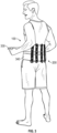
- FIG. 8 illustrates a back view of lumbar-supporting back-bracing apparatus 100
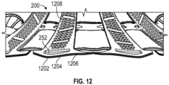
- FIGs. 9-12 illustrate magnified back, front or substantially cross-sectional views of different portions of apparatus 100, in accordance with some embodiments.
- Lumbar-supporting back-bracing apparatus 100 can comprise a support portion 200 and a belt portion 300.
- support portion 200 comprises a plurality of posterior ribs 210 configured to abut and extend vertically along a lumbar portion of user's lower back.
- Posterior ribs 210 may be rigid or semirigid but, in some embodiments, at least partially conformable to the anatomy of the user's lower back. While the present disclosure contemplates any number of posterior ribs 210, at least FIGs. 1, 2 , 8 and 9 illustrate four posterior ribs laterally spaced from one another. In some embodiments, each of posterior ribs 210 is laterally spaced from an adjacent rib by a same distance. In some other embodiments, posterior ribs 210 are laterally spaced from adjacent rib(s) by one or more different distances. In some embodiments, each of posterior ribs 210 can have a same length, for example, 21 centimeters or 26 centimeters. However, the present disclosure is not so limited and contemplates posterior ribs 210 of any same or varied suitable length(s).
- Each of posterior ribs 210 can comprise a first upper slot 222 and a second upper slot 224 disposed on either side of an upper portion of the respective posterior rib 210.
- First and second upper slots 222, 224 are configured to receive one or more straps of belt portion 300 to thereby secure the apparatus 100 against a low back and torso of the user.
- Each of posterior ribs 210 can also comprise a first lower slot 232 and a second lower slot 234 disposed on either side of a lower portion of the respective posterior rib 210.
- First and second lower slots 232, 234 are configured to receive one or more straps of belt portion 300 to thereby secure the apparatus 100 against a low back and torso of the user.
- one or more of posterior ribs 210 can have at least a first indicator 252 disposed at one end of the posterior rib(s) and, optionally, a second indicator 254 disposed at a second end of the posterior rib(s).
- First and/or second indicators 252, 254 can identify the top and/or bottom ends, respectively, of apparatus 100 and may aid the user in assembling and/or putting on apparatus 100 in the proper orientation.
- first and/or second indicators 252, 254 will be described in more detail below, in connection with one or more other features of support portion 200.
- Posterior ribs 210 are coupled to one another via a bracing web component 240 comprising a plurality of crossing and/or x-shaped structures.
- each posterior rib 210 is coupled to an adjacent posterior rib via one such crossing and/or x-shaped structure of bracing web component 240.
- Such crossing and/or x-shaped structures provide damping of vibrations through apparatus 100 and thereby protection for the low back of the user.
- any of posterior ribs 210, slots 222, 224, 232, 234, and bracing web component 240, individually or formed together as an integral piece, can comprise a layered structure, as illustrated in more detail in at least FIG. 12 .
- a layered structure can comprise stiffening steel, metal or otherwise rigid but conformable stays 1208 sandwiched between an outer layer 1206 comprising, for example, polyurethane overinjected onto textile and an inner layer 1202 comprising, for example, a soft, absorbent material, such as cloth, foam, etc.
- outer layer 1206 and/or inner layer 1202 may comprise any respective suitable material(s).
- an example stay 1208 is illustrated in FIG.
- any number of stays can be disposed between inner layer 1202 and outer layer 1206 and such stays may have any suitable shape(s) to form any portion of ribs 210, slots 222, 224, 232, 234 and/or crossing and/or x-shaped structure of bracing web component 240 as described anywhere herein.
- Outer layer 1206 may provide external protection and durability for apparatus 100.
- Inner layer 1202 may provide added comfort to the user, both in terms of padding and ability to wick moisture away from the user's torso and/or low back.
- the stiffening stays 1208 may provide rigid but at least partially conformal support for the low back of the user.
- the stiffening stays 1208 are disposed within posterior ribs 210 of support portion 200.
- the stiffening stays 1208 are also disposed in at least a portion of material defining one or more of slots 222, 224, 232, 234, for example along a perimeter of one or more of slots 222, 224, 232, 234.
- the stiffening stays 1208 also define at least a portion of bracing web component 240, for example forming at least a portion of the plurality of crossing and/or x-shaped structures to improve rigidity and/or the torsion-withstanding ability of bracing web component 240 compared to embodiments not having such stiffening stays disposed within bracing web component 240.
- the stiffening stays 1208 may be secured between inner layer 1202 and outer layer 1206 utilizing any suitable process, for example, a thermo-compressing process in which an adhesive is applied to facing sides of inner layer 1202 and outer layer 1206 and activated by heat and/or pressure by pressing the layers together with sufficient force and/or heat.
- a thermo-compressing process in which an adhesive is applied to facing sides of inner layer 1202 and outer layer 1206 and activated by heat and/or pressure by pressing the layers together with sufficient force and/or heat.
- first and second indicators 252, 254 can be formed from an indicator layer 1204 disposed between inner layer 1202 and outer layer 1206 before the multiple layers are secured to one another, as otherwise described above.
- indicator layer 1204 comprises a fabric, plastic or any other suitable material having a color and/or texture different from one or both of inner layer 1202 and outer layer 1206 such that, when rendered visible to a user, indicator layer 1204 is readily identifiable at first and/or second indicators 252, 254 for at least an orientation-indicating purpose.
- adhesive may be similarly applied to at least a portion of one or both sides of indicator layer 1206 before it is disposed between inner layer 1202 and outer layer 1206.
- a die cutting operation may be utilized to cut away excess portions of inner and outer layers 1202, 1206 and, in some embodiments also indicator layer 1204, to thereby realize at least the crossing and/or x-shaped structure of bracing web component 240.
- a die cutting operation can also be utilized to cut away excess portions of inner and outer layers 1202, 1206 in the same operation to form indicator(s) 252 and/or 254, once exposed through a window in at least outer layer 1206.
- indicator layer 1204 At least a portion of outer layer 1206 can be cut away to, thereby, expose a portion of indicator layer 1204 at the location(s) of one or both of first and second indicators 252, 254.
- Utilizing indicator layer 1204 as opposed to a conventional sticker or marker functioning as an indicator allows formation of indicators 252, 254 in fewer steps, since a die cutting operation that defines one or more sections of support portion 200 can also be utilized to remove the portion of outer layer 1206 and exposing the portion(s) of indicator layer 1204 at one or both of indicators 252, 254 in the same operation.
- such a die cutting operation can also be utilized to cut away excess portions of at least inner and outer layers 1202, 1206 in the same operation to form posterior ribs 210 including the first and second upper and lower slots 222, 224, 232, 234.
- one or more portions of the apparatus elastics e.g., one or more parts of belt portion 300
- belt portion 300 can comprise an inner strap 305.
- Inner strap 305 is configured as the inner-most belt layer to be wrapped around the torso and lower back of the user.
- Inner strap 305 can comprise a first end 310 and a second end 320.
- inner strap 305 splits at a first seam 307, from a unitary piece near first end 310 into an upper portion 305a and a lower portion 305b, each configured to pass respectively through the upper slots 222, 224 and lower slots 232, 234 of one or more of posterior ribs 210 of support portion 200.
- inner strap 305 can further comprise a first central portion 305c coupled to and extending medially from a central portion of first seam 307 to a central portion of an adjacent side of support portion 200.
- inner strap 305 can further comprise a second central portion 305d coupled to and extending medially from a central portion of second seam 309 to a central portion of an adjacent side of support portion 200. As illustrated in FIG.
- first and second central portions 305c, 305d can be disposed at a backside of one or both of upper and lower inner straps 305a, 305b.
- first and second central portions 305c, 305d can be disposed at a frontside of one or both of upper and lower inner straps 305a, 305b.
- first and second central portions 305c, 305d can provide direct anchors of inner strap 305 to support portion 200 and, thereby provide additional aid in properly alignment of support portion 200 with respect to the user's lower back and/or torso and/or with respect to inner strap 305.
- first and second ends 310, 320 of inner strap 305 can further comprise respective fasteners 317, 327 such as hook and loop fasteners or any other suitable fastener.
- first end 310 further comprises a first pocket or loop 315 and second end 320 comprises a second pocket or loop 325 configured such that a user can hold onto these pockets or loops 315, 325 with either hand as lie or she pulls inner strap 305 tightly around his or her torso and low back and brings fastener(s) 317 of first end 310 into physical contact with fastener(s) 327 of second end 320, thereby allowing for an appropriately snug securement of inner strap 305 around the torso and low back of the user.
- belt portion 300 also comprises at least one outer strap 330, 340.
- at least FIGs. 1 and 2 illustrate an upper outer strap 330 and a lower outer strap 340.
- Upper outer strap 330 and lower outer strap 340 are each configured as an outer-most belt layer to be wrapped around the torso and lower back of the user and around inner strap 305.
- Upper outer strap 330 is configured to pass through the upper slots 222, 224 of one or more of posterior ribs 210 of support portion 200 and, in some cases, over the upper portion of inner strap 305 as it does so.
- upper outer strap 330 is sewn or otherwise bonded to at least a portion of the upper portion of inner strap 305, for example at a first seam 335 disposed near and to a same side of support portion 200 as a first end 332 of upper inner strap 305a, at a second seam 337 disposed near and to a same side of support portion 200 as a second end 334 of upper inner strap 305a, and/or at a central seam 264 disposed substantially at a centerline of support portion 200.
- central seam 264 may sew or otherwise bond both upper outer strap 330 and inner upper strap 305a to the support portion 200 of apparatus 200 substantially at the centerline of support portion 200. Accordingly, in some such embodiments, central seam 264 may extend through to and along the backside of support portion 200 as illustrated in at least FIGs. 8 and 9 .
- upper outer strap 330 is separate from and not sewn or otherwise permanently bonded to the upper portion of inner strap 305.
- first and second ends 332, 334 of upper outer strap 330 can each further comprise fasteners, similar to inner strap 305, such as hook and loop fasteners or any other suitable type of fasteners.
- a user can hold onto first and second ends 332, 334 with either hand as he or she pulls upper outer strap 330 tightly around his or her torso, low back and inner strap 305 and fastens the fastener(s) of first end 332 to one of inner strap 305 or second end 334, thereby allowing for an appropriately snug securement of upper outer strap 330 around the torso and low back of the user.
- At least one of upper outer strap 330, its first end 332 or its second end 334 can further comprise an indicator, similar to or different from indicator 252 of support portion 200 of apparatus 100, to identify upper outer strap 330 as the outer strap that extends through upper slots 222, 224 of posterior ribs 210 and aid the user in putting apparatus 100 on in the proper orientation.
- This pulling, wrapping and securing of upper outer strap 330 is illustrated in at least FIG. 3 and illustration 706 of FIG. 7 .
- Lower outer strap 340 is configured to pass through the lower slots 232, 234 of one or more of posterior ribs 210 of support portion 200 and, in some cases, over the lower portion of inner strap 305 as it does so.
- lower outer strap 340 is sewn or otherwise bonded to at least a portion of the lower portion of inner strap 305, for example at a first seam 345 disposed near and to a same side of support portion 200 as a first end 342 of lower inner strap 305b, at a second seam 347 disposed near and to a same side of support portion 200 as a second end 334 of upper inner strap 305b, and/or at a central seam 262 disposed substantially at a centerline of support portion 200.
- central seam 262 may sew or otherwise bond both lower outer strap 340 and inner lower strap 305b to the support portion 200 of apparatus 200 substantially at the centerline of support portion 200. Accordingly, in some such embodiments, central seam 262 may extend to and along the backside of support portion 200 as illustrated in at least FIGs. 9 and 10 .
- lower outer strap 340 is separate from and not sewn or otherwise permanently bonded to the lower portion of inner strap 305.
- first and second ends 342, 344 of lower outer strap 340 can each further comprise fasteners, similar to inner strap 305, such as hook and loop fasteners or any other suitable type of fasteners.
- a user can hold onto first and second ends 342, 344 with either hand as he or she pulls lower outer strap 340 tightly around his or her torso, low back and inner strap 305 and fastens the fastener(s) of first end 342 to one of inner strap 305 or second end 344, thereby allowing for an appropriately snug securement of lower outer strap 340 around the torso and low back of the user.
- At least one of lower outer strap 340, its first end 342 or its second end 344 can further comprise an indicator, similar to, or different from, indicator 254 of support portion 200 of apparatus 1 00, to identify lower outer strap 340 as the outer strap that extends through lower slots 232, 234 of posterior ribs 210 and aid the user in putting apparatus 100 on in the proper orientation.
- This pulling, wrapping and securing of lower outer strap 340 is illustrated in at least illustration 708 of FIG. 7 .
- FIG. 4 illustrates an anterior view of the apparatus 100 with belt portion 300 secured around the torso of the user and first and second ends 332, 334 of upper outer strap 330 and first and second ends 342, 344 of lower outer strap 340 each secured to a portion of already-secured inner strap 305.
- FIG. 5 illustrates a posterior view of apparatus 100 with support portion 200 secured against the low back of the user.
- FIG. 6 illustrates a magnified view of an embodiment in which first and second ends 332, 334 of upper outer strap 330 overlap and are at least partially secured to one another and in which first and second ends 342, 344 of lower outer strap 340 overlap and are at least partially secured to one another, rather than or in addition to being at least partially secured to a portion of already-secured inner strap 305.
- Inner strap 305 (including, for example, upper, lower and central portions 305a-305d), upper outer strap 330 and lower outer strap 340 are easy to clean and maintain and provide better low back support for a user of apparatus 100 compared to conventional back brace designs.
- one or more of inner strap 305, upper outer strap 330 and lower outer strap 340 can comprise antimicrobial, anti--odor, thermoregulatory and/or hypoallergenic "on steam" materials.
- one or more of inner strap 305, upper outer strap 330 and lower outer strap 340 can comprise a honeycomb design such as Artico TM fabric.
- one or more of inner strap 305, upper outer strap 330 and lower outer strap 340 can be formed in such a way so as not to have stitched external borders to provided better comfort for the user compared to conventional back brace designs in which stitched external borders might otherwise dig into and/or otherwise create uncomfortable pressure points on the torso of the user.
- one or more of inner strap 305, upper outer strap 330 and lower outer strap 340 can be fabricated or made available in one or more of a plurality of sizes.
- extra small (XS) for an example waist size of 56-68 cm
- small (S) for an example waist size of 68-82 cm
- medium (M) for an example waist size of 82-98 cm
- large (L) for an example waist size of 98-116 cm
- extra large (XL) for an example waist size of 116-136 cm.
- FIG. 13 illustrates a flowchart 1300 corresponding to such a method of manufacturing a lumbar-supporting back-bracing apparatus, in accordance with some example embodiments.
- Block 1302 includes forming a support portion of a lumbar-supporting, back-bracing apparatus.
- An example includes apparatus 100 as previously discussed in connection with FIGs. 1- 12. This forming the support portion can be carried out as described in connection with at least blocks 1304 and 1306 below and/or as previously described in connection with any figure herein.
- Block 1304 includes forming a plurality of posterior ribs configured to abut and extend along a low back of a user by sandwiching rigid metallic stays between an outer layer comprising polyurethane overinjected onto textile and an inner layer comprising a soft, absorbant material.
- rigid metallic stays 1208 can be sandwiched between outer layer 1206 comprising, for example, polyurethane overinjected onto textile and inner layer 1202 comprising, for example, a soft, absorbant material.
- At least one of posterior ribs 210 comprises first upper slot 222 disposed at a first upper side of the rib and second upper slot 224 disposed at a second upper side of rib 210 opposite the first upper side, and first lower slot 232 disposed at a first lower side of rib 210 and second lower slot 234 disposed at a second lower side of rib 210 opposite the first lower side.
- the ribs 210 are rigid yet at least partially conformable to the low back of the user.
- ribs 210 are laterally spaced from adjacent ribs by a same distance.
- ribs 210 are laterally spaced from an adjacent rib by a first distance and at least one other of the ribs 210 is laterally spaced from an adjacent rib by a second distance different from the first distance.
- ribs 210 each have a same length.
- forming support portion 200 further includes forming or otherwise providing first indicator 252 at one end of at least one of ribs 210 to indicate an orientation of apparatus 100.
- forming or otherwise providing first indicator 252 comprises further disposing indicator layer 1204 between outer layer 1206 and inner layer 1202 and removing a portion of at least outer layer 1206, thereby exposing at least a portion of indicator layer 1204 at the end of rib(s) 210.
- Block 1306 includes forming a bracing web component comprising a plurality of crossing structures from at least the outer layer and the inner layer, wherein each rib of the plurality of posterior ribs is physically coupled to an adjacent rib of the plurality of posterior ribs by at least one of the crossing structures.
- the x-shaped crossing structures of bracing web component 240 can be formed from at least outer layer 1206 and inner layer 1202. Each rib 210 is physically coupled to an adjacent rib 210 by at least one of these x-shaped crossing structures.
- each of the plurality of crossing structures of bracing web component 240 are formed as an x-shaped structure that is configured to dampen vibrations in apparatus 100. In such embodiments, each x-shaped structure can couple one of the ribs to an adjacent rib.
- Block 1308 includes providing a belt portion of the lumbar-supporting, back-bracing apparatus.
- An example includes belt portion 300 of apparatus 100 as previously discussed in connection with FIGs. 1-12 . This forming the belt portion can be carried out as described in connection with at least blocks 1310, 1312 and 1314 below.
- Block 1310 includes forming an inner strap that is configured to be coupled to the support portion and to wrap around a torso and a low back of the user and thereby the apparatus to be secured around the torso of the user.
- inner strap 305 is configured to be coupled to support portion 200 and to wrap around a torso and low back of the user so the apparatus can be secured around the torso of the user.
- forming the inner strap includes disposing first fastener 317 at first end 310 of inner strap 305 and disposing second fastener 327 at second end 320 of inner strap 305 such that when first and second ends 310, 320 overlap one another first and second fasteners 317, 327 couple to one another, thereby securing inner strap 305 around the torso of the user.
- forming inner strap 305 further includes forming first pocket or loop 315 at first end 310 of inner strap 305 and forming second pocket or loop 325 at second end 320 of inner strap 3050, thereby providing structures for the user to grasp while securing inner strap 305 around the torso.
- inner strap 305 splits from a unitary piece adjacent to first end 310 into upper portion 305a configured to pass through first and second upper slots 222, 224 of ribs 210 and lower portion 305b configured to pass through first and second lower slots 232, 234 of ribs 210, upper portion 305a and lower portion 3005b merging back into a unitary piece adjacent to second end 320.
- inner strap 305 further splits from the unitary piece adjacent to first end 310 into first central portion 305c configured to extend to and couple to a first adjacent side of support portion 200, and upper portion 305a, lower portion 305b and second central portion 305d merge back into the unitary piece adjacent to second end 320 such that second central portion 305b is configured to extend to and couple to a second adjacent side of support portion 200.
- Block 1312 includes forming an upper outer strap that is configured to pass through the first and second upper slots of the at least one rib of the plurality of posterior ribs and to wrap around around the inner strap, the torso and the low back of the user.
- upper outer strap 330 is configured to pass through the first and second upper slots 222, 224 of ribs 210 and to wrap around inner strap 305, the torso and the low back of the user.
- forming upper outer strap 330 includes disposing a first fastener at first end 332 and disposing a second fastener at second end 334, the first and second fasteners of upper outer strap 330 configured to respectively secure first and second ends 332, 334 of upper outer strap 330 to one another and/or to inner strap 305.
- forming upper outer strap 330 includes sewing upper outer strap 330 to at least a portion of inner strap 305.
- Block 1314 includes forming a lower outer strap that is configured to pass through the first and second lower slots of the at least one rib of the plurality of posterior ribs and to wrap around the inner strap, the torso and the low back of the user.
- lower outer strap 340 is configured to pass through the first and second lower slots 232, 234 of ribs 210 and to wrap around inner strap 305, the torso and the low back of the user.
- forming lower outer strap 340 includes disposing a first fastener at first end 342 and disposing a second fastener at second end 344, the first and second fasteners of lower outer strap 340 configured to respectively secure first and second ends 342, 344 of lower outer strap 340 to one another and/or to inner strap 305.
- forming lower outer strap 340 includes sewing lower outer strap 340 to at least a portion of inner strap 305.
- At least one of inner strap 305, upper outer strap 330 and lower outer strap 340 include at least one of an antimicrobial, an anti-odor, a thermoregulatory and/or a hypoallergenic material.
- an external border of at least one of inner strap 305, upper outer strap 330 and lower outer strap 340 does not comprise stitching.
- FIG. 14 illustrates a flowchart 1400 corresponding to such a method of using a lumbar-supporting back-bracing apparatus, in accordance with some example embodiments.
- Block 1402 includes disposing a plurality of posterior ribs of a support portion of the lumbar-supporting back-bracing apparatus against a low back of a user.
- a user can dispose posterior ribs 210 of support portion 200 of apparatus 100 against a low back of a user, as previously discussed in connection with at least one of FIGs. 1-12 .
- At least one of posterior ribs 210 includes a first upper slot 222 disposed at a first upper side of rib 210 and a second upper slot 224 disposed at a second upper side of rib 210 opposite the first upper side, and a first lower slot 232 disposed at a first lower side of rib 210 and a second lower slot 234 disposed at a second lower side of rib 210 opposite the first lower side.
- support portion 200 further includes a bracing web component 240 comprising a plurality of crossing structures, each of the crossing structures physically coupling two adjacent ribs 210 of the plurality of posterior ribs.
- the ribs 210 are rigid yet at least partially conformable to the low back of the user. In some embodiments, ribs 210 are laterally spaced from adjacent ribs by a same distance. In some embodiments, at least one of the ribs 210 is laterally spaced from an adjacent rib by a first distance and at least one other of the ribs 210 is laterally spaced from an adjacent rib by a second distance different from the first distance. In some embodiments, ribs 210 each have a same length.
- first indicator 252 is disposed at one end of at least one of ribs 210 to indicate an orientation of apparatus 100.
- indicator layer 1204 is disposed between an outer layer 1206 and an inner layer 1202 and a portion of at least outer layer 1206 is removed, thereby exposing at least a portion of indicator layer 1204 at the end of rib(s) 210.
- each of the plurality of crossing structures of the bracing web component comprises an x-shaped structure configured to dampen vibrations in apparatus 100.
- each x-shaped structure couples two adjacent ribs 210 of the plurality of posterior ribs.
- at least the plurality of posterior ribs have a bonded layered structure comprising rigid metallic stays 1208 sandwiched between an outer layer 1206 comprising, for example, polyurethane overinjected onto textile, and an inner layer 1202 comprising, for example, a soft, absorbant material.
- Block 1404 includes securing an inner strap of a belt portion of the lumbar-supporting back-bracing apparatus around a torso and a low back of the user, thereby securing the apparatus around the torso of the user.
- a user or practicioner can secure inner strap 305 of belt portion 300 of lumbar-supporting back-bracing apparatus 100 around a torso and a low back of the user, thereby securing apparatus 100 around the torso of the user.
- inner strap 305 comprises a first end 310 having a first fastener 317 and a second end 320 having a second fastener 327.
- first and second ends 310, 320 are configured to overlap one another sufficiently that first and second fasteners 317, 327 couple to one another and thereby secure inner strap 305 around the torso of the user.
- first end 310 of inner strap 305 comprises a first pocket or loop 315 and second end 320 of inner strap 305 comprises a second pocket or loop 325.
- Such first and second pockets or loops 315, 325 provide structure for the user or practitioner to grasp while securing inner strap 305 around the torso of the user.
- inner strap 305 splits from a unitary piece adjacent to first end 310 into an upper portion 305a configured to pass through first and second upper slots 222, 224 of the at least one rib 210 of the plurality of posterior ribs and a lower portion 305b configured to pass through first and second lower slots 232, 234 of the at least one rib 210 of the plurality of posterior ribs. Upper portion 305a and lower portion 305b merge back into a unitary piece adjacent to second end 320 of inner strap 305. In some embodiments, inner strap 305 further splits from the unitary piece adjacent to first end 310 into a first central portion 305c configured to extend to and couple to a first adjacent side of support portion 200.
- upper portion 305a, lower portion 305b and a second central portion 305d merge back into the unitary piece adjacent to second end 320 of inner strap 305.
- second central portion 305d is configured to extend to and couple to a second adjacent side of support portion 200.
- Block 1406 includes securing an upper outer strap of the belt portion around around the inner strap, the torso and the low back of the user, the upper outer strap configured to pass through the first and second upper slots of the at least one rib of the plurality of posterior ribs.
- a user or practitioner can secure upper outer strap 330 of the belt portion around around inner strap 305, the torso and the low back of the user.
- Upper outer strap 330 is configured to pass through first and second upper slots 222, 224 of the at least one rib 210 of the plurality of posterior ribs.
- upper outer strap 330 comprises a first end 332 having a first fastener and a second end 334 having a second fastener, the first and second fasteners of upper outer strap 330 configured to respectively secure first and second ends 332, 334 of upper outer strap 330 to one another and/or to inner strap 305.
- upper outer strap 330 is sewn to at least a portion of inner strap 305.
- Block 1408 includes securing a lower outer strap of the belt portion around the inner strap, the torso and the low back of the user, the lower outer strap configured to pass through the first and second lower slots of the at least one rib of the plurality of posterior ribs.
- a user or practitioner can secure a lower outer strap 340 of belt portion 300 around inner strap 305, the torso and the low back of the user.
- Lower outer strap 340 is configured to pass through first and second lower slots 232, 234 of the at least one rib 210 of the plurality of posterior ribs.
- lower outer strap 340 comprises a first end 342 having a first fastener and a second end 344 having a second fastener.
- the first and second fasteners of lower outer strap 340 are configured to respectively secure first and second ends 342, 344 of lower outer strap 340 to one another and/or to inner strap 305.
- lower outer strap 340 is sewn to at least a portion of inner strap 305.
- an external border of at least one of inner strap 305, upper outer strap 330 and lower outer strap 340 does not comprise stitching.
Landscapes
- Health & Medical Sciences (AREA)
- Nursing (AREA)
- Orthopedic Medicine & Surgery (AREA)
- Engineering & Computer Science (AREA)
- Biomedical Technology (AREA)
- Heart & Thoracic Surgery (AREA)
- Vascular Medicine (AREA)
- Life Sciences & Earth Sciences (AREA)
- Animal Behavior & Ethology (AREA)
- General Health & Medical Sciences (AREA)
- Public Health (AREA)
- Veterinary Medicine (AREA)
- Orthopedics, Nursing, And Contraception (AREA)
Claims (15)
- Appareil de soutien lombaire pour le dos (100), l'appareil comprenant :une partie de support (200) comprenant :
une pluralité de nervures postérieures (210) configurées pour s'appuyer et s'étendre le long du bas du dos d'un utilisateur, chacune de la pluralité de nervures postérieures comprenant :une première fente supérieure (222) disposée sur un premier côté supérieur de la nervure (210) et une seconde fente supérieure (224) disposée sur un second côté supérieur de la nervure opposé au premier côté supérieur, etune première fente inférieure (232) disposée sur un premier côté inférieur de la nervure (210) et une seconde fente inférieure (234) disposée sur un second côté inférieur de la nervure opposé au premier côté inférieur,etune partie de ceinture (300) comprenant :une sangle intérieure (305) couplée à la partie de support et configurée pour s'enrouler autour du torse et du bas du dos de l'utilisateur et ainsi fixer l'appareil autour du torse de l'utilisateur,une sangle extérieure supérieure (330) configurée pour passer à travers les première et seconde fentes supérieures de l'au moins une nervure de la pluralité de nervures postérieures et s'enrouler autour de la sangle intérieure, du torse et du bas du dos de l'utilisateur, etune sangle extérieure inférieure (340) configurée pour passer à travers les première et secondes fentes inférieures de l'au moins une nervure de la pluralité de nervures postérieures et s'enrouler autour de la sangle intérieure, du torse et du bas du dos de l'utilisateur, caractérisé en ce que la partie de support comprend en outre un élément de rebord comprenant une pluralité de structures de croisement rigides en forme de x, dans lequel chaque nervure de la pluralité de nervures postérieures est physiquement couplée à une nervure adjacente de la pluralité de nervures postérieures par une structure de croisement en forme de x respective, amortissant ainsi les vibrations dans l'appareil. - Appareil selon la revendication 1, dans lequel la pluralité de nervures postérieures est rigide mais au moins partiellement adaptable au bas du dos de l'utilisateur.
- Appareil selon la revendication 1 ou la revendication 2, dans lequel chaque nervure de la pluralité de nervures est espacée latéralement d'une nervure adjacente de la pluralité de nervures d'une même distance.
- Appareil selon la revendication 1 ou selon la revendication 2, dans lequel au moins une nervure de la pluralité de nervures est espacée latéralement d'une nervure adjacente de la pluralité de nervures d'une première distance et au moins une autre nervure de la pluralité de nervures est espacée latéralement d'une nervure adjacente de la pluralité de nervures d'une seconde distance différente de la première.
- Appareil selon la revendication 1, dans lequel au moins une nervure de la pluralité de nervures comprend un premier indicateur (252) disposé à une extrémité de la nervure et configuré pour indiquer une orientation de l'appareil, le premier indicateur comprenant une couche indicatrice (1204) disposée à l'intérieur d'au moins une nervure de la pluralité de nervures et exposée à travers une fenêtre dans au moins une couche extérieure (1206) d'au moins une nervure.
- Appareil selon la revendication 1, dans lequel au moins la pluralité de nervures postérieures présentent une structure en couches collées comprenant des tiges métalliques rigides prises en sandwich entre une couche extérieure comprenant du polyuréthane surinjecté sur du textile et une couche intérieure comprenant un matériau souple et absorbant.
- Appareil selon la revendication 1, dans lequel la sangle intérieure comprend une première extrémité (310) avec une première fermeture (317) et une seconde extrémité (320) avec une seconde fermeture (327), la première et la seconde extrémité étant configurées pour se chevaucher suffisamment pour que la première et la seconde fermeture se couplent l'une à l'autre et fixent ainsi la sangle intérieure autour du torse de l'utilisateur.
- Appareil selon la revendication 7, dans lequel la première extrémité de la sangle intérieure comprend une première poche ou boucle (315) et la seconde extrémité de la sangle intérieure comprend une seconde poche ou boucle (325), les premières et secondes poches ou boucles fournissant une structure que l'utilisateur peut saisir tout en fixant la sangle intérieure autour du torse.
- Appareil selon la revendication 7, dans lequel la sangle intérieure se sépare d'une pièce unitaire adjacente à la première extrémité (310) en une partie supérieure (305 a) configurée pour passer à travers les première et seconde fentes supérieures (222, 224) d'au moins une nervure (210) de la pluralité de nervures postérieures et une partie inférieure (305 b) configurée pour passer à travers les première et seconde fentes inférieures (232, 234) d'au moins une nervure de la pluralité de nervures postérieures, la partie supérieure et la partie inférieure fusionnant à nouveau en une pièce unitaire adjacente à la seconde extrémité.
- Appareil selon la revendication 9, dans lequel :la sangle intérieure (305) se sépare en outre de la pièce unitaire adjacente à la première extrémité (310) en une première partie centrale (305 c) configurée pour s'étendre et s'accoupler à un premier côté adjacent de la partie de support (200) ; etla partie supérieure (305 a), la partie inférieure (305 b) et une seconde partie centrale (305 d) se fondent à nouveau dans la pièce unitaire adjacente à la seconde extrémité (320), la seconde partie centrale (305 b) étant configurée pour s'étendre et se coupler à un second côté adjacent de la partie de support (200).
- Appareil selon la revendication 1, dans lequel la sangle extérieure supérieure (330) comprend une première extrémité (332) dotée d'une première attache et une seconde extrémité dotée d'une seconde attache, les premières et secondes attaches de la sangle extérieure supérieure étant configurées pour fixer respectivement les premières et secondes extrémités de la sangle extérieure supérieure l'une à l'autre et/ou à la sangle intérieure.
- Appareil selon la revendication 1, dans lequel au moins une des sangles extérieures supérieures (330) et inférieures (340) est cousue à au moins une partie de la sangle intérieure (305)
- Appareil selon la revendication 1, dans lequel la sangle extérieure inférieure (340) comprend une première extrémité dotée d'une première attache et une seconde extrémité dotée d'une seconde attache, les premières et secondes attaches de la sangle extérieure supérieure étant configurées pour fixer respectivement les premières et secondes extrémités de la sangle extérieure inférieure l'une à l'autre et/ou à la sangle intérieure.
- Procédé de fabrication d'un appareil de soutien lombaire (100) selon l'une quelconque des revendications 1 à 13, le procédé comprenant :
la formation d'une partie de support (200) en :
formant une pluralité de nervures postérieures (210) configurées pour s'appuyer et s'étendre le long du bas du dos d'un utilisateur en prenant en sandwich des baleines métalliques rigides (1208) entre une couche extérieure (1206) comprenant du polyuréthane surinjecté sur du textile et une couche intérieure (1202) comprenant un matériau souple et absorbant, au moins une nervure de la pluralité de nervures postérieures comprenant :une première fente supérieure (222) disposée sur un premier côté supérieur de la nervure et une seconde fente supérieure disposée sur un second côté supérieur de la nervure opposé au premier côté supérieur, etune première fente inférieure (232) disposée sur un premier côté inférieur de la nervure et une seconde fente inférieure disposée sur un second côté inférieur de la nervure opposé au premier côté inférieur,la formation d'un composant de rebord (240) comprenant une pluralité de structures de croisement rigides en forme de x à partir d'au moins la couche externe et la couche interne, dans lequel chaque nervure de la pluralité de nervures postérieures est physiquement couplée à une nervure adjacente de la pluralité de nervures postérieures par une structure de croisement rigide en forme de x respective, amortissant ainsi les vibrations de l'appareil ; et la fourniture d'une partie de courroie (300) en :formant une sangle intérieure (305) configurée pour être couplée à la partie de support (200) et pour entourer le torse et le bas du dos de l'utilisateur, ce qui permet de fixer l'appareil autour du torse de l'utilisateur,la formation d'une sangle extérieure supérieure (330) configurée pour passer à travers les première et seconde fentes supérieures (222, 224) de l'au moins une nervure de la pluralité de nervures postérieures et s'enrouler autour de la sangle intérieure, du torse et du bas du dos de l'utilisateur, etla formation d'une sangle extérieure inférieure (340) configurée pour passer à travers les première et seconde fentes inférieures (232, 234) de l'au moins une nervure de la pluralité de nervures postérieures et s'enrouler autour de la sangle intérieure, du torse et du bas du dos de l'utilisateur, et - Procédé selon la revendication 14, comprenant en outre la formation d'une première poche ou boucle (315) à une première extrémité (310) de la sangle intérieure (305) et la formation d'une seconde poche ou boucle (325) à une seconde extrémité (320) de la sangle intérieure (305), fournissant ainsi des structures que l'utilisateur peut saisir tout en fixant la sangle intérieure (305) autour du torse.
Applications Claiming Priority (3)
| Application Number | Priority Date | Filing Date | Title |
|---|---|---|---|
| US202062975298P | 2020-02-12 | 2020-02-12 | |
| US202063101208P | 2020-03-10 | 2020-03-10 | |
| PCT/US2021/017403 WO2021163151A1 (fr) | 2020-02-12 | 2021-02-10 | Appareil et méthodes de renforcement du dos supportant les lombaires |
Publications (2)
| Publication Number | Publication Date |
|---|---|
| EP4103113A1 EP4103113A1 (fr) | 2022-12-21 |
| EP4103113B1 true EP4103113B1 (fr) | 2023-12-13 |
Family
ID=74856939
Family Applications (1)
| Application Number | Title | Priority Date | Filing Date |
|---|---|---|---|
| EP21709841.7A Active EP4103113B1 (fr) | 2020-02-12 | 2021-02-10 | Appareil et méthodes de renforcement du dos supportant les lombaires |
Country Status (5)
| Country | Link |
|---|---|
| US (2) | US11564825B2 (fr) |
| EP (1) | EP4103113B1 (fr) |
| ES (1) | ES2978978T3 (fr) |
| TN (1) | TN2022000220A1 (fr) |
| WO (1) | WO2021163151A1 (fr) |
Family Cites Families (21)
| Publication number | Priority date | Publication date | Assignee | Title |
|---|---|---|---|---|
| FR1104562A (fr) | 1954-05-14 | 1955-11-22 | Ceinture de maintien orthopédique | |
| US2955293A (en) * | 1958-01-09 | 1960-10-11 | Lucille C Peterson | Protective shoulder cover |
| US4080962A (en) * | 1975-07-24 | 1978-03-28 | Joseph Berkeley | Posture-training brace |
| DE2837620C2 (de) * | 1978-08-29 | 1982-05-13 | Joachim Prof. Dr.Med. 6200 Wiesbaden Eichler | Rückenstützbandage |
| US4976257A (en) | 1989-08-15 | 1990-12-11 | Timothy W. Akin | Hyperextension brace |
| FR2687062B1 (fr) * | 1992-02-07 | 1999-07-30 | Charles Lelli | Ceinture de maintien lombaire. |
| US5547462A (en) * | 1995-09-14 | 1996-08-20 | Lanigan; William T. | Back brace |
| US6666838B2 (en) | 2002-04-22 | 2003-12-23 | Deroyal Industries, Inc. | Low-profile lumbo-sacral orthosis |
| US7070572B2 (en) * | 2002-10-17 | 2006-07-04 | Amei Technologies Inc. | Dynamically adjustable stabilization brace |
| US7500944B2 (en) * | 2003-06-27 | 2009-03-10 | Ethicon Endo-Surgery, Inc. | Implantable band with attachment mechanism |
| US8192383B2 (en) * | 2009-08-07 | 2012-06-05 | The Seaberg Company, Inc. | Emergency stabilization of a fractured pelvis |
| US8808213B2 (en) * | 2010-05-28 | 2014-08-19 | Hendricks Orthotic Prosthetic Enterprises, Inc. | Mechanically advantaged spinal system and method |
| KR20120111830A (ko) | 2011-04-02 | 2012-10-11 | 조경일 | 옆구리판에 탄력 조임밴드 통로를 구비한 허리보호대 |
| US9119975B2 (en) | 2012-02-15 | 2015-09-01 | 3M Innovative Properties Company | Respirator waist belt |
| ITMI20121169A1 (it) | 2012-07-03 | 2014-01-04 | Indaco Srl | Corsetto. |
| US9414955B2 (en) * | 2014-08-14 | 2016-08-16 | American Ingenuity, LLC | Back support device |
| FR3045315B1 (fr) * | 2015-12-21 | 2020-05-15 | Thuasne | Dispositif medical destine a soutenir au moins une zone du corps |
| US20180160838A1 (en) * | 2016-12-14 | 2018-06-14 | Jiangsu Hilong Hometextiles Co., Ltd. | Shading Composite Film and Producing Method Thereof |
| CN207886322U (zh) | 2017-05-01 | 2018-09-21 | 深圳体联网健康科技有限公司 | 无缝护腰 |
| US11540935B2 (en) | 2017-06-07 | 2023-01-03 | Ortho Systems | Welded back brace |
| SE540816C2 (en) * | 2017-07-17 | 2018-11-20 | Ortrud Medical Ab | Tourniquet |
-
2021
- 2021-02-10 WO PCT/US2021/017403 patent/WO2021163151A1/fr not_active Ceased
- 2021-02-10 ES ES21709841T patent/ES2978978T3/es active Active
- 2021-02-10 TN TNP/2022/000220A patent/TN2022000220A1/en unknown
- 2021-02-10 EP EP21709841.7A patent/EP4103113B1/fr active Active
- 2021-02-10 US US17/172,536 patent/US11564825B2/en active Active
-
2023
- 2023-01-24 US US18/100,860 patent/US20230225894A1/en not_active Abandoned
Also Published As
| Publication number | Publication date |
|---|---|
| US20210244560A1 (en) | 2021-08-12 |
| US11564825B2 (en) | 2023-01-31 |
| US20230225894A1 (en) | 2023-07-20 |
| ES2978978T3 (es) | 2024-09-23 |
| WO2021163151A1 (fr) | 2021-08-19 |
| EP4103113A1 (fr) | 2022-12-21 |
| TN2022000220A1 (en) | 2024-04-01 |
Similar Documents
| Publication | Publication Date | Title |
|---|---|---|
| US5188585A (en) | Lumbo-sacral orthopedic support | |
| US5536246A (en) | Back support system with interchangeable and positionally adjustable orthotic supports | |
| US5445601A (en) | Back support device having bands securing the support plate | |
| US5205815A (en) | Athletic back support apparatus | |
| US6582382B2 (en) | Orthopedic supports | |
| US4691696A (en) | Lumbar spinal brace | |
| JP4679061B2 (ja) | 整形パッドを備えるリフティング用のスリング | |
| US5334134A (en) | Lumbosacral back support releasably secured to a stabilizing belt | |
| US20100204629A1 (en) | Adjustable lower back brace with posture alignment guide | |
| WO2014181128A1 (fr) | Orthèse de cou | |
| WO1999017687A1 (fr) | Orthese lombo-sacree | |
| WO2004037135A1 (fr) | Panneau de support arriere a surfaces convexes pour support musculaire | |
| US20160113801A1 (en) | Dynamic hip brace, hip brace kit and method of use | |
| US20200100928A1 (en) | Ankle brace devices, systems, and methods | |
| US12053405B2 (en) | Ankle brace devices, systems, and methods | |
| JP5733713B2 (ja) | 衝撃吸収装具 | |
| EP4103113B1 (fr) | Appareil et méthodes de renforcement du dos supportant les lombaires | |
| JPH0325773Y2 (fr) | ||
| JPH0532113Y2 (fr) | ||
| JP2000037407A (ja) | 積層整形装具 | |
| US20120289874A1 (en) | Spinal Posture Brace | |
| CN210697917U (zh) | 一种负重式护腰带 | |
| JP2001346820A (ja) | 腰痛治療用ガードル | |
| AU2002307834A1 (en) | Orthopedic supports |
Legal Events
| Date | Code | Title | Description |
|---|---|---|---|
| STAA | Information on the status of an ep patent application or granted ep patent |
Free format text: STATUS: UNKNOWN |
|
| STAA | Information on the status of an ep patent application or granted ep patent |
Free format text: STATUS: THE INTERNATIONAL PUBLICATION HAS BEEN MADE |
|
| PUAI | Public reference made under article 153(3) epc to a published international application that has entered the european phase |
Free format text: ORIGINAL CODE: 0009012 |
|
| STAA | Information on the status of an ep patent application or granted ep patent |
Free format text: STATUS: REQUEST FOR EXAMINATION WAS MADE |
|
| 17P | Request for examination filed |
Effective date: 20220810 |
|
| AK | Designated contracting states |
Kind code of ref document: A1 Designated state(s): AL AT BE BG CH CY CZ DE DK EE ES FI FR GB GR HR HU IE IS IT LI LT LU LV MC MK MT NL NO PL PT RO RS SE SI SK SM TR |
|
| DAV | Request for validation of the european patent (deleted) | ||
| DAX | Request for extension of the european patent (deleted) | ||
| GRAP | Despatch of communication of intention to grant a patent |
Free format text: ORIGINAL CODE: EPIDOSNIGR1 |
|
| STAA | Information on the status of an ep patent application or granted ep patent |
Free format text: STATUS: GRANT OF PATENT IS INTENDED |
|
| INTG | Intention to grant announced |
Effective date: 20230628 |
|
| P01 | Opt-out of the competence of the unified patent court (upc) registered |
Effective date: 20230831 |
|
| GRAS | Grant fee paid |
Free format text: ORIGINAL CODE: EPIDOSNIGR3 |
|
| GRAA | (expected) grant |
Free format text: ORIGINAL CODE: 0009210 |
|
| STAA | Information on the status of an ep patent application or granted ep patent |
Free format text: STATUS: THE PATENT HAS BEEN GRANTED |
|
| AK | Designated contracting states |
Kind code of ref document: B1 Designated state(s): AL AT BE BG CH CY CZ DE DK EE ES FI FR GB GR HR HU IE IS IT LI LT LU LV MC MK MT NL NO PL PT RO RS SE SI SK SM TR |
|
| REG | Reference to a national code |
Ref country code: GB Ref legal event code: FG4D |
|
| REG | Reference to a national code |
Ref country code: CH Ref legal event code: EP |
|
| REG | Reference to a national code |
Ref country code: DE Ref legal event code: R096 Ref document number: 602021007697 Country of ref document: DE |
|
| REG | Reference to a national code |
Ref country code: IE Ref legal event code: FG4D |
|
| PG25 | Lapsed in a contracting state [announced via postgrant information from national office to epo] |
Ref country code: GR Free format text: LAPSE BECAUSE OF FAILURE TO SUBMIT A TRANSLATION OF THE DESCRIPTION OR TO PAY THE FEE WITHIN THE PRESCRIBED TIME-LIMIT Effective date: 20240314 |
|
| REG | Reference to a national code |
Ref country code: LT Ref legal event code: MG9D |
|
| PG25 | Lapsed in a contracting state [announced via postgrant information from national office to epo] |
Ref country code: LT Free format text: LAPSE BECAUSE OF FAILURE TO SUBMIT A TRANSLATION OF THE DESCRIPTION OR TO PAY THE FEE WITHIN THE PRESCRIBED TIME-LIMIT Effective date: 20231213 |
|
| REG | Reference to a national code |
Ref country code: NL Ref legal event code: MP Effective date: 20231213 |
|
| PG25 | Lapsed in a contracting state [announced via postgrant information from national office to epo] |
Ref country code: LT Free format text: LAPSE BECAUSE OF FAILURE TO SUBMIT A TRANSLATION OF THE DESCRIPTION OR TO PAY THE FEE WITHIN THE PRESCRIBED TIME-LIMIT Effective date: 20231213 Ref country code: GR Free format text: LAPSE BECAUSE OF FAILURE TO SUBMIT A TRANSLATION OF THE DESCRIPTION OR TO PAY THE FEE WITHIN THE PRESCRIBED TIME-LIMIT Effective date: 20240314 Ref country code: BG Free format text: LAPSE BECAUSE OF FAILURE TO SUBMIT A TRANSLATION OF THE DESCRIPTION OR TO PAY THE FEE WITHIN THE PRESCRIBED TIME-LIMIT Effective date: 20240313 |
|
| REG | Reference to a national code |
Ref country code: AT Ref legal event code: MK05 Ref document number: 1639839 Country of ref document: AT Kind code of ref document: T Effective date: 20231213 |
|
| PG25 | Lapsed in a contracting state [announced via postgrant information from national office to epo] |
Ref country code: NL Free format text: LAPSE BECAUSE OF FAILURE TO SUBMIT A TRANSLATION OF THE DESCRIPTION OR TO PAY THE FEE WITHIN THE PRESCRIBED TIME-LIMIT Effective date: 20231213 |
|
| PG25 | Lapsed in a contracting state [announced via postgrant information from national office to epo] |
Ref country code: SE Free format text: LAPSE BECAUSE OF FAILURE TO SUBMIT A TRANSLATION OF THE DESCRIPTION OR TO PAY THE FEE WITHIN THE PRESCRIBED TIME-LIMIT Effective date: 20231213 Ref country code: RS Free format text: LAPSE BECAUSE OF FAILURE TO SUBMIT A TRANSLATION OF THE DESCRIPTION OR TO PAY THE FEE WITHIN THE PRESCRIBED TIME-LIMIT Effective date: 20231213 Ref country code: NO Free format text: LAPSE BECAUSE OF FAILURE TO SUBMIT A TRANSLATION OF THE DESCRIPTION OR TO PAY THE FEE WITHIN THE PRESCRIBED TIME-LIMIT Effective date: 20240313 Ref country code: NL Free format text: LAPSE BECAUSE OF FAILURE TO SUBMIT A TRANSLATION OF THE DESCRIPTION OR TO PAY THE FEE WITHIN THE PRESCRIBED TIME-LIMIT Effective date: 20231213 Ref country code: LV Free format text: LAPSE BECAUSE OF FAILURE TO SUBMIT A TRANSLATION OF THE DESCRIPTION OR TO PAY THE FEE WITHIN THE PRESCRIBED TIME-LIMIT Effective date: 20231213 Ref country code: HR Free format text: LAPSE BECAUSE OF FAILURE TO SUBMIT A TRANSLATION OF THE DESCRIPTION OR TO PAY THE FEE WITHIN THE PRESCRIBED TIME-LIMIT Effective date: 20231213 |
|
| PG25 | Lapsed in a contracting state [announced via postgrant information from national office to epo] |
Ref country code: IS Free format text: LAPSE BECAUSE OF FAILURE TO SUBMIT A TRANSLATION OF THE DESCRIPTION OR TO PAY THE FEE WITHIN THE PRESCRIBED TIME-LIMIT Effective date: 20240413 |
|
| PG25 | Lapsed in a contracting state [announced via postgrant information from national office to epo] |
Ref country code: AT Free format text: LAPSE BECAUSE OF FAILURE TO SUBMIT A TRANSLATION OF THE DESCRIPTION OR TO PAY THE FEE WITHIN THE PRESCRIBED TIME-LIMIT Effective date: 20231213 Ref country code: CZ Free format text: LAPSE BECAUSE OF FAILURE TO SUBMIT A TRANSLATION OF THE DESCRIPTION OR TO PAY THE FEE WITHIN THE PRESCRIBED TIME-LIMIT Effective date: 20231213 |
|
| PG25 | Lapsed in a contracting state [announced via postgrant information from national office to epo] |
Ref country code: SK Free format text: LAPSE BECAUSE OF FAILURE TO SUBMIT A TRANSLATION OF THE DESCRIPTION OR TO PAY THE FEE WITHIN THE PRESCRIBED TIME-LIMIT Effective date: 20231213 |
|
| PG25 | Lapsed in a contracting state [announced via postgrant information from national office to epo] |
Ref country code: SM Free format text: LAPSE BECAUSE OF FAILURE TO SUBMIT A TRANSLATION OF THE DESCRIPTION OR TO PAY THE FEE WITHIN THE PRESCRIBED TIME-LIMIT Effective date: 20231213 Ref country code: SK Free format text: LAPSE BECAUSE OF FAILURE TO SUBMIT A TRANSLATION OF THE DESCRIPTION OR TO PAY THE FEE WITHIN THE PRESCRIBED TIME-LIMIT Effective date: 20231213 Ref country code: RO Free format text: LAPSE BECAUSE OF FAILURE TO SUBMIT A TRANSLATION OF THE DESCRIPTION OR TO PAY THE FEE WITHIN THE PRESCRIBED TIME-LIMIT Effective date: 20231213 Ref country code: IT Free format text: LAPSE BECAUSE OF FAILURE TO SUBMIT A TRANSLATION OF THE DESCRIPTION OR TO PAY THE FEE WITHIN THE PRESCRIBED TIME-LIMIT Effective date: 20231213 Ref country code: IS Free format text: LAPSE BECAUSE OF FAILURE TO SUBMIT A TRANSLATION OF THE DESCRIPTION OR TO PAY THE FEE WITHIN THE PRESCRIBED TIME-LIMIT Effective date: 20240413 Ref country code: EE Free format text: LAPSE BECAUSE OF FAILURE TO SUBMIT A TRANSLATION OF THE DESCRIPTION OR TO PAY THE FEE WITHIN THE PRESCRIBED TIME-LIMIT Effective date: 20231213 Ref country code: CZ Free format text: LAPSE BECAUSE OF FAILURE TO SUBMIT A TRANSLATION OF THE DESCRIPTION OR TO PAY THE FEE WITHIN THE PRESCRIBED TIME-LIMIT Effective date: 20231213 Ref country code: AT Free format text: LAPSE BECAUSE OF FAILURE TO SUBMIT A TRANSLATION OF THE DESCRIPTION OR TO PAY THE FEE WITHIN THE PRESCRIBED TIME-LIMIT Effective date: 20231213 |
|
| PG25 | Lapsed in a contracting state [announced via postgrant information from national office to epo] |
Ref country code: PL Free format text: LAPSE BECAUSE OF FAILURE TO SUBMIT A TRANSLATION OF THE DESCRIPTION OR TO PAY THE FEE WITHIN THE PRESCRIBED TIME-LIMIT Effective date: 20231213 Ref country code: PT Free format text: LAPSE BECAUSE OF FAILURE TO SUBMIT A TRANSLATION OF THE DESCRIPTION OR TO PAY THE FEE WITHIN THE PRESCRIBED TIME-LIMIT Effective date: 20240415 |
|
| PG25 | Lapsed in a contracting state [announced via postgrant information from national office to epo] |
Ref country code: PT Free format text: LAPSE BECAUSE OF FAILURE TO SUBMIT A TRANSLATION OF THE DESCRIPTION OR TO PAY THE FEE WITHIN THE PRESCRIBED TIME-LIMIT Effective date: 20240415 Ref country code: PL Free format text: LAPSE BECAUSE OF FAILURE TO SUBMIT A TRANSLATION OF THE DESCRIPTION OR TO PAY THE FEE WITHIN THE PRESCRIBED TIME-LIMIT Effective date: 20231213 |
|
| REG | Reference to a national code |
Ref country code: DE Ref legal event code: R097 Ref document number: 602021007697 Country of ref document: DE |
|
| REG | Reference to a national code |
Ref country code: ES Ref legal event code: FG2A Ref document number: 2978978 Country of ref document: ES Kind code of ref document: T3 Effective date: 20240923 |
|
| PG25 | Lapsed in a contracting state [announced via postgrant information from national office to epo] |
Ref country code: MC Free format text: LAPSE BECAUSE OF FAILURE TO SUBMIT A TRANSLATION OF THE DESCRIPTION OR TO PAY THE FEE WITHIN THE PRESCRIBED TIME-LIMIT Effective date: 20231213 |
|
| PG25 | Lapsed in a contracting state [announced via postgrant information from national office to epo] |
Ref country code: DK Free format text: LAPSE BECAUSE OF FAILURE TO SUBMIT A TRANSLATION OF THE DESCRIPTION OR TO PAY THE FEE WITHIN THE PRESCRIBED TIME-LIMIT Effective date: 20231213 |
|
| PG25 | Lapsed in a contracting state [announced via postgrant information from national office to epo] |
Ref country code: LU Free format text: LAPSE BECAUSE OF NON-PAYMENT OF DUE FEES Effective date: 20240210 |
|
| PLBE | No opposition filed within time limit |
Free format text: ORIGINAL CODE: 0009261 |
|
| STAA | Information on the status of an ep patent application or granted ep patent |
Free format text: STATUS: NO OPPOSITION FILED WITHIN TIME LIMIT |
|
| PG25 | Lapsed in a contracting state [announced via postgrant information from national office to epo] |
Ref country code: SI Free format text: LAPSE BECAUSE OF FAILURE TO SUBMIT A TRANSLATION OF THE DESCRIPTION OR TO PAY THE FEE WITHIN THE PRESCRIBED TIME-LIMIT Effective date: 20231213 |
|
| PG25 | Lapsed in a contracting state [announced via postgrant information from national office to epo] |
Ref country code: SI Free format text: LAPSE BECAUSE OF FAILURE TO SUBMIT A TRANSLATION OF THE DESCRIPTION OR TO PAY THE FEE WITHIN THE PRESCRIBED TIME-LIMIT Effective date: 20231213 Ref country code: LU Free format text: LAPSE BECAUSE OF NON-PAYMENT OF DUE FEES Effective date: 20240210 Ref country code: DK Free format text: LAPSE BECAUSE OF FAILURE TO SUBMIT A TRANSLATION OF THE DESCRIPTION OR TO PAY THE FEE WITHIN THE PRESCRIBED TIME-LIMIT Effective date: 20231213 |
|
| 26N | No opposition filed |
Effective date: 20240916 |
|
| REG | Reference to a national code |
Ref country code: BE Ref legal event code: MM Effective date: 20240229 |
|
| PG25 | Lapsed in a contracting state [announced via postgrant information from national office to epo] |
Ref country code: BE Free format text: LAPSE BECAUSE OF NON-PAYMENT OF DUE FEES Effective date: 20240229 |
|
| PG25 | Lapsed in a contracting state [announced via postgrant information from national office to epo] |
Ref country code: IE Free format text: LAPSE BECAUSE OF NON-PAYMENT OF DUE FEES Effective date: 20240210 |
|
| PG25 | Lapsed in a contracting state [announced via postgrant information from national office to epo] |
Ref country code: BE Free format text: LAPSE BECAUSE OF NON-PAYMENT OF DUE FEES Effective date: 20240229 Ref country code: IE Free format text: LAPSE BECAUSE OF NON-PAYMENT OF DUE FEES Effective date: 20240210 |
|
| PG25 | Lapsed in a contracting state [announced via postgrant information from national office to epo] |
Ref country code: CY Free format text: LAPSE BECAUSE OF FAILURE TO SUBMIT A TRANSLATION OF THE DESCRIPTION OR TO PAY THE FEE WITHIN THE PRESCRIBED TIME-LIMIT; INVALID AB INITIO Effective date: 20210210 |
|
| PG25 | Lapsed in a contracting state [announced via postgrant information from national office to epo] |
Ref country code: HU Free format text: LAPSE BECAUSE OF FAILURE TO SUBMIT A TRANSLATION OF THE DESCRIPTION OR TO PAY THE FEE WITHIN THE PRESCRIBED TIME-LIMIT; INVALID AB INITIO Effective date: 20210210 |
|
| PG25 | Lapsed in a contracting state [announced via postgrant information from national office to epo] |
Ref country code: FI Free format text: LAPSE BECAUSE OF FAILURE TO SUBMIT A TRANSLATION OF THE DESCRIPTION OR TO PAY THE FEE WITHIN THE PRESCRIBED TIME-LIMIT Effective date: 20231213 |
|
| PG25 | Lapsed in a contracting state [announced via postgrant information from national office to epo] |
Ref country code: TR Free format text: LAPSE BECAUSE OF FAILURE TO SUBMIT A TRANSLATION OF THE DESCRIPTION OR TO PAY THE FEE WITHIN THE PRESCRIBED TIME-LIMIT Effective date: 20231213 |
|
| REG | Reference to a national code |
Ref country code: CH Ref legal event code: U11 Free format text: ST27 STATUS EVENT CODE: U-0-0-U10-U11 (AS PROVIDED BY THE NATIONAL OFFICE) Effective date: 20260301 |
|
| PGFP | Annual fee paid to national office [announced via postgrant information from national office to epo] |
Ref country code: GB Payment date: 20260227 Year of fee payment: 6 |
|
| PGFP | Annual fee paid to national office [announced via postgrant information from national office to epo] |
Ref country code: ES Payment date: 20260302 Year of fee payment: 6 |
|
| PGFP | Annual fee paid to national office [announced via postgrant information from national office to epo] |
Ref country code: DE Payment date: 20260227 Year of fee payment: 6 |
|
| PGFP | Annual fee paid to national office [announced via postgrant information from national office to epo] |
Ref country code: FR Payment date: 20260225 Year of fee payment: 6 |
|
| PGFP | Annual fee paid to national office [announced via postgrant information from national office to epo] |
Ref country code: CH Payment date: 20260301 Year of fee payment: 6 |