EP4103860B1 - Optimierung des verschleisses von flugzeugbremsen - Google Patents
Optimierung des verschleisses von flugzeugbremsen Download PDFInfo
- Publication number
- EP4103860B1 EP4103860B1 EP21753612.7A EP21753612A EP4103860B1 EP 4103860 B1 EP4103860 B1 EP 4103860B1 EP 21753612 A EP21753612 A EP 21753612A EP 4103860 B1 EP4103860 B1 EP 4103860B1
- Authority
- EP
- European Patent Office
- Prior art keywords
- carbon disc
- disc brake
- brakes
- recited
- brake
- Prior art date
- Legal status (The legal status is an assumption and is not a legal conclusion. Google has not performed a legal analysis and makes no representation as to the accuracy of the status listed.)
- Active
Links
Images

Classifications
-
- B—PERFORMING OPERATIONS; TRANSPORTING
- B60—VEHICLES IN GENERAL
- B60T—VEHICLE BRAKE CONTROL SYSTEMS OR PARTS THEREOF; BRAKE CONTROL SYSTEMS OR PARTS THEREOF, IN GENERAL; ARRANGEMENT OF BRAKING ELEMENTS ON VEHICLES IN GENERAL; PORTABLE DEVICES FOR PREVENTING UNWANTED MOVEMENT OF VEHICLES; VEHICLE MODIFICATIONS TO FACILITATE COOLING OF BRAKES
- B60T17/00—Component parts, details, or accessories of power brake systems not covered by groups B60T8/00, B60T13/00 or B60T15/00, or presenting other characteristic features
- B60T17/18—Safety devices; Monitoring
- B60T17/22—Devices for monitoring or checking brake systems; Signal devices
- B60T17/221—Procedure or apparatus for checking or keeping in a correct functioning condition of brake systems
-
- B—PERFORMING OPERATIONS; TRANSPORTING
- B60—VEHICLES IN GENERAL
- B60T—VEHICLE BRAKE CONTROL SYSTEMS OR PARTS THEREOF; BRAKE CONTROL SYSTEMS OR PARTS THEREOF, IN GENERAL; ARRANGEMENT OF BRAKING ELEMENTS ON VEHICLES IN GENERAL; PORTABLE DEVICES FOR PREVENTING UNWANTED MOVEMENT OF VEHICLES; VEHICLE MODIFICATIONS TO FACILITATE COOLING OF BRAKES
- B60T17/00—Component parts, details, or accessories of power brake systems not covered by groups B60T8/00, B60T13/00 or B60T15/00, or presenting other characteristic features
- B60T17/18—Safety devices; Monitoring
- B60T17/22—Devices for monitoring or checking brake systems; Signal devices
-
- B—PERFORMING OPERATIONS; TRANSPORTING
- B60—VEHICLES IN GENERAL
- B60T—VEHICLE BRAKE CONTROL SYSTEMS OR PARTS THEREOF; BRAKE CONTROL SYSTEMS OR PARTS THEREOF, IN GENERAL; ARRANGEMENT OF BRAKING ELEMENTS ON VEHICLES IN GENERAL; PORTABLE DEVICES FOR PREVENTING UNWANTED MOVEMENT OF VEHICLES; VEHICLE MODIFICATIONS TO FACILITATE COOLING OF BRAKES
- B60T8/00—Arrangements for adjusting wheel-braking force to meet varying vehicular or ground-surface conditions, e.g. limiting or varying distribution of braking force
- B60T8/17—Using electrical or electronic regulation means to control braking
- B60T8/1701—Braking or traction control means specially adapted for particular types of vehicles
- B60T8/1703—Braking or traction control means specially adapted for particular types of vehicles for aircrafts
-
- B—PERFORMING OPERATIONS; TRANSPORTING
- B60—VEHICLES IN GENERAL
- B60T—VEHICLE BRAKE CONTROL SYSTEMS OR PARTS THEREOF; BRAKE CONTROL SYSTEMS OR PARTS THEREOF, IN GENERAL; ARRANGEMENT OF BRAKING ELEMENTS ON VEHICLES IN GENERAL; PORTABLE DEVICES FOR PREVENTING UNWANTED MOVEMENT OF VEHICLES; VEHICLE MODIFICATIONS TO FACILITATE COOLING OF BRAKES
- B60T8/00—Arrangements for adjusting wheel-braking force to meet varying vehicular or ground-surface conditions, e.g. limiting or varying distribution of braking force
- B60T8/32—Arrangements for adjusting wheel-braking force to meet varying vehicular or ground-surface conditions, e.g. limiting or varying distribution of braking force responsive to a speed condition, e.g. acceleration or deceleration
- B60T8/88—Arrangements for adjusting wheel-braking force to meet varying vehicular or ground-surface conditions, e.g. limiting or varying distribution of braking force responsive to a speed condition, e.g. acceleration or deceleration with failure responsive means, i.e. means for detecting and indicating faulty operation of the speed responsive control means
- B60T8/885—Arrangements for adjusting wheel-braking force to meet varying vehicular or ground-surface conditions, e.g. limiting or varying distribution of braking force responsive to a speed condition, e.g. acceleration or deceleration with failure responsive means, i.e. means for detecting and indicating faulty operation of the speed responsive control means using electrical circuitry
-
- B—PERFORMING OPERATIONS; TRANSPORTING
- B64—AIRCRAFT; AVIATION; COSMONAUTICS
- B64C—AEROPLANES; HELICOPTERS
- B64C25/00—Alighting gear
- B64C25/32—Alighting gear characterised by elements which contact the ground or similar surface
- B64C25/42—Arrangement or adaptation of brakes
- B64C25/44—Actuating mechanisms
-
- B—PERFORMING OPERATIONS; TRANSPORTING
- B60—VEHICLES IN GENERAL
- B60T—VEHICLE BRAKE CONTROL SYSTEMS OR PARTS THEREOF; BRAKE CONTROL SYSTEMS OR PARTS THEREOF, IN GENERAL; ARRANGEMENT OF BRAKING ELEMENTS ON VEHICLES IN GENERAL; PORTABLE DEVICES FOR PREVENTING UNWANTED MOVEMENT OF VEHICLES; VEHICLE MODIFICATIONS TO FACILITATE COOLING OF BRAKES
- B60T2270/00—Further aspects of brake control systems not otherwise provided for
- B60T2270/40—Failsafe aspects of brake control systems
- B60T2270/406—Test-mode; Self-diagnosis
Definitions
- Carbon disc brakes are commonly used in aircraft applications to facilitate control of the aircraft during taxiing before take-off and after landing. Because heat stacks made of carbon discs are lightweight and quite effective in providing the desired braking functions, they are very attractive for use in the aircraft industry. However, carbon discs are quite expensive and, accordingly, their wear rate must be managed to ensure cost effectiveness without reducing braking efficiency.
- BTMS brake temperature monitoring system
- BCS brake control system
- the BTMS data is often inconsistent across the aircraft, or has a significant lag, which can distort the true brake temperature and make determinations based on temperature potentially imprecise.
- Fig. 1 is an example of dynamometer wear assessment for an aircraft and shows that the optimum BTMS reading (horizontal axis) to minimize brake disc wear is achieved by maximizing the BTMS readout to high levels while remaining suitable to allow the aircraft to take off-often in the range of 200-250° C.
- temperatures this high are generally difficult for an operator to practically achieve.
- the graph of Fig. 1 further illustrates the potential to improve brake life for the subject aircraft, particularly at the coldest BTMS temperature, shown at 0-0 in the graph of the BTMS readout departing the gate.
- a temperature readout greater than 0-6 aircraft takeoff is not permitted because the brake temperature is at such a level that the brakes could not withstand a rejected takeoff (RTO) of maximum possible energy.
- RTO rejected takeoff
- takeoff is permitted.
- Graph 10 of Fig. 1 shows the typical correlation between BTMS readout departing the gate and the relative wear life of the carbon discs in a standard system, while it is most desired that the graph be that indicated by the numeral 12, which, at the very least, demonstrates significant benefit for cold taxi operations and consistently higher wear life expectations in the upper allowable temperature range.
- US 2019/291708 A1 discloses an apparatus for reducing brake wear having a brake de-selection function for selectively disabling at least one brake on a vehicle, and a controller, wherein the controller is configured to receive torque information which relates to torque reacted by a brake on the vehicle during a braking event and wheel speed information which relates to a speed of a wheel associated with the brake during the braking event, calculate an energy input into the brake during the braking event, based on the received torque information and the received wheel speed information, determine whether the calculated energy input meets at least one predefined energy input criterion, and activate the brake de-selection function if the calculated energy input meets the at least one predefined energy input criterion.
- Another aspect of the invention is the provision of a method for aircraft brake wear optimization that actually focuses on energy dissipated by the brakes during taxiing, rather than relying on temperature read-outs from the aircraft brake temperature monitoring system.
- a further aspect of the invention is the provision of a method for aircraft brake wear optimization that inhibits and enables selective groupings of brakes for taxiing operations in an effort to obtain a uniform wear of those brakes.
- Yet a further aspect of the invention is to provide a method for aircraft brake wear optimization in which brakes can operate at elevated temperatures during taxiing, but with such operation within a range capable of accommodating a rejected takeoff.
- the present invention provides a method for optimizing aircraft carbon disc brake wear according to claim 1.
- a method for optimizing aircraft carbon disc brake wear comprising: calculating the actual energy absorbed by each carbon disc brake during taxiing operations; from the calculations of energy absorbed, determining a current carbon disc brake temperature; and selectively inhibiting and enabling actuation of said carbon disc brakes as a function of disc brake temperature.
- the invention herein replaces or adjusts those readings with a calculation of the approximate energy absorbed by each brake during taxiing operations. It does so by utilizing data such as brake torque, aircraft mass, and wheel speed signals. From the calculation of absorbed energy, a more suitable, accurate, and timely brake temperature can be determined. The temperature determined from brake energy calculations is then used as part of the switching decision as to the selection, timing and duration of the actuation of the various brakes in order to elevate the brake stack temperatures to a desired minimum temperature.
- the invention contemplates enhancement of the temperature calculation by using the brake stack mass available on various aircraft generating the electronic brake wear data.
- the invention further contemplates that the pilot may always have essentially instant overriding control over all of the brakes based on pedal or other inputs. Since changing the number of active brakes has a potential for changing the perceived braking responsiveness of the aircraft, such can be managed with appropriate pedal curves and other features.
- the invention contemplates various bases for switching or selecting the groupings of brakes to be activated during taxiing to achieve the benefits of improved carbon disc wear.
- the grouping of brakes will be switched or changed on each flight leg.
- the switching can be indexed at any appropriate time such as when the aircraft lifts off of the runway at the beginning of a flight or sets down on the runway at the end of a flight, both of which can be accommodated by a weight on wheels (WOW) or other similar sensor.
- WOW weight on wheels
- the grouping of brakes for activation and use can be switched based on time periods, such as daily.
- time periods such as daily.
- the selected groupings or pairs will be employed for taxiing for the entirety of the day and for all flight legs during that day.
- the activated groupings or pairs of brakes can be switched at any time that the then-activated brakes reach a predetermined temperature level.
- a predetermined temperature level could be a temperature beyond which a rejected takeoff (RTO) could not be accommodated.
- RTO rejected takeoff
- Other suitable levels can be envisioned.
- NVM non-volatile memory
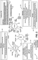
- the invention is generally that of a taxi brake select (TBS) nature and, more particularly, a Smart TBS system, designated generally by the numeral 20 in Fig. 2 .
- TBS taxi brake select
- the TBS system stays in waiting and disarmed or inactivated as at 22, while monitoring various inputs as identified at 24.
- the TBS system monitors a weight on wheels (WOW) switch to determine whether the aircraft is in the air or has landed. It further monitors wheel speed as provided by various wheel speed transducers. It further monitors the status of the aircraft as to whether it is parked or actually available for movement. Pedal deflection or depression by the pilot or co-pilot is also monitored, as is the position of the throttle.
- the system further monitors whether an automatic braking system (ABS) is employed and whether it is requesting TBS activity.
- ABS automatic braking system
- the TBS system stays in waiting, or is disarmed, in the event there is a fault sensed in the normal system or if the throttle is advanced greater than a certain amount, such as greater than 10°.
- a determination is further made whether the aircraft is in a normal parked condition, an engine-run-up parked position, whether it is under external towing, or whether it has engaged re-park (where the brake disc stack has been re-engaged to reset the brakes when the aircraft is parked and the brake discs have had an opportunity to cool down, with the associated disc shrinkage requiring a reapplication of brake pressure).
- the TBS system remains disarmed and/or in waiting until all conditions have been met for enablement of the system and rendering the system active as at 26, with those conditions shown in the block 28.
- the TBS system may be activated or overruled by the pilot/co-pilot. While in TBS active at 26, numerous data is monitored to control the actuation and release of the aircraft brakes during taxiing. The actual brakes to be employed are determined by data from the flight log as to whether the brake pairs are selected by flight, daily, or as function of temperature, as presented above. Further signals are received from the Smart TBS system, such as will be discussed hereinafter. Brake pedal data is received and considered, as is wheel speed data, park status data, electronic brake wear data (if available), BTMS brake temperatures, and throttle position data.
- the TBS When the TBS is active, as at 26, it will selectively inhibit different sets of brakes, such as the inboard or outboard sets, depending upon the strut configuration, allowing the brakes that are not inhibited to control the braking function during taxiing.
- the inhibiting may be of the associated electric motor actuator controllers (EMACs), such as the inboard EMACs at 30, or the outboard EMACs at 32.
- EMACs electric motor actuator controllers
- the toggling or selection for enabling or inhibiting between the inboard and outboard EMACs 30, 32 simply occurs by reading from a non-volatile memory the last status of EMAC activation when brake pedal depression is beneath a predetermined level, such as 10%, and wheel speeds are less than a predetermined level, such as 40 knots, at which time the enabling and disabling of EMACs is toggled from the reading from the non-volatile memory.
- a predetermined level such as 10%
- wheel speeds are less than a predetermined level, such as 40 knots
- the Smart TBS toggling or switching between the inboard and outboard EMACs generally follows a process as at 36. Again, with pedals depressed less than a predetermined threshold, such as 10%, and wheel speed below a level such as 40 knots, the prior state of activation and inhibiting of the EMACs 30, 32 is determined from the flight log, and then toggling is engaged consistent with one of the three embodiments discussed above. That toggling may occur according to one embodiment on each flight leg, or another embodiment at the beginning of each day, or according to yet a third embodiment when a brake stack exceeds or falls below a preset temperature threshold. In each event, the flight log is incremented to effect and confirm the appropriate toggling on the occurrence of the next similar event.
- a predetermined threshold such as 10%
- wheel speed below a level such as 40 knots
- taxi brake select activity may be terminated and brake activity restored to its normal operation without taxi brake select, and that such activity involves restoring the brake pedal to control the activity of both the inboard and outboard EMACs 30, 32.
- Restoring of the pedal is effected by a pedal ramp 38 with the process generalized in the restore-pedals-step 40.
- the data relevant to the implementation of taxi brake select that is being departed is stored in non-volatile memory such that the next involvement of taxi brake select will have that data available for inhibiting the necessary EMACs.
- a determination is then made as to the state of the aircraft, including whether the aircraft is in normal park, engine run-up park, external tow, re-park, a throttle advance exceeding a threshold such as 10°, a brake pedal depression exceeding 70%, a wheel speed exceeding a set threshold such as 42 knots, a fault in the normal operating system, or a BTMS brake temperature output greater than a predetermined threshold, then the brake pedals will be restored, as at 40, by means of a pedal ramp at 38.
- the pedal ramp speed is set according to the criteria of 44.
- a pedal ramp is necessary when departing TBS operations for a number of reasons. If there is greater than 70% of brake pedal travel, then turning TBS off and engaging the full complement of brakes through EMACs 30, 32 could cause significant grabbing of the brakes and discomfort to passengers. Accordingly, a slow ramp might be desired. If, however, wheel speed were below a threshold, such as 10 knots or the like, or if the throttle were to be suddenly advanced, a fast ramp of pedal recovery for a couple of seconds might be desired, such as when the aircraft is making its final taxi turns onto the runway before takeoff. See such criteria at 44, effecting either a slow ramp or a fast ramp at 38.
- TBS is exited after an appropriate ramp has been selected, ensuring that TBS is not engaged.
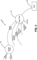
- pedals are returned to their appropriate position with full braking capability and with all EMACs engaged by the process of Fig. 3 , designated by the numeral 50.
- the pedals are processed at 52 as to their measure of depression and return to normal operation.
- the outboard inhibit and inboard inhibit are removed, and the slow ramp and fast ramp controls are turned off.
- Control CnfPins may also be provided to the applied pedal function 54 to fully restore the pedals as at 56.
- These pins are provided in electronic brake systems with multiple controllers to identify which motors on a particular wheel are being controlled. This helps to identify if the EMAC is controlling an inboard or outboard wheel. Of course, the specific details are left to the particular braking architecture of the aircraft.
- a thermal model is contemplated to predict brake temperature and BTMS temperature, according to one embodiment of the invention. This is done by integrating the sum of input heat flows Q to each temperature node divided by the mass m and specific heat c of the associated nodes of the heat disc stack.
- the thermal model accounts for all heat transfer modes, including conduction, convection, and radiation, along with internal energy generation. Inputs of ambient temperature, cooling air speed, and wear state may be provided for these calculations. Standard heat transfer equations for conduction, convection, and radiation, as are well known to those skilled in the art, are used.
- Internal energy generation is used to account for the energy input due to braking events.
- the inputs of wheel velocity and aircraft mass per wheel are used to compute this energy in this embodiment.
- a correction factor is multiplied by the difference between the measured and calculated BTMS temperatures as a feedback mechanism to adjust the model predictions based on the available BTMS temperature measurement.
- This correction factor can be adjusted based on parameters such as node temperatures and the rate of change of these temperatures. It can be made zero to avoid correction, if desired.
- the final value of this correction is added to the braking energy as an additional energy generation component to arrive at the total internal energy generation.
- the predicted brake temperature can be corrected using the measured BTMS temperature by including it in the feedback loop with the predicted BTMS temperature, even though no direct brake temperature feedback is available.
- This process employs a BTMS having a measured (monitored) temperature output and a calculated temperature output.
Landscapes
- Engineering & Computer Science (AREA)
- Mechanical Engineering (AREA)
- Transportation (AREA)
- Aviation & Aerospace Engineering (AREA)
- Braking Arrangements (AREA)
- Regulating Braking Force (AREA)
Claims (14)
- Verfahren zur Optimierung des Verschleißes von Flugzeug-Kohlenstoffscheibenbremsen während des Rollens, umfassend:Berechnen, aus den Parametern Bremsmoment, Radgeschwindigkeit, Bremspedalbetätigung, Flugzeugmasse pro Rad, Umgebungstemperatur und Zustand des Bremsenverschleißes, der tatsächliche Energie, die von jeder Kohlenstoffscheibenbremse während der Rollvorgänge aufgenommen wird;Bestimmen, aus den Berechnungen der absorbierten Energie, einer aktuellen Temperatur der Kohlenstoffscheibenbremse; undselektives Sperren und Freigeben der Betätigung der Kohlenstoffscheibenbremsen in Abhängigkeit von der Scheibenbremsentemperatur.
- Verfahren zur Optimierung des Verschleißes von Flugzeug-Kohlenstoffscheibenbremsen nach Anspruch 1, wobei der Schritt des selektiven Sperren und Freigebens sowohl die Reihenfolge des Sperrens und Freigebens als auch die Dauer des Sperrens und Freigebens steuert.
- Verfahren zur Optimierung des Verschleißes von Flugzeug-Kohlenstoffscheibenbremsen nach Anspruch 2, wobei die Reihenfolge und die Dauer der Sperrens und Freigebens die Kohlenstoffscheibenbremsen auf einer bevorzugten Betriebstemperatur halten, um den Verschleiß zu optimieren.
- Verfahren zur Optimierung des Verschleißes von Flugzeug-Kohlenstoffscheibenbremsen nach Anspruch 2, wobei die Kohlenstoffscheibenbremsen für die Aktivierung in Bremsengruppen gesperrt und freigegeben werden.
- Verfahren zur Optimierung des Verschleißes von Flugzeug-Kohlenstoffscheibenbremsen nach Anspruch 4, wobei die für das Sperren und Freigeben ausgewählten Bremsengruppen auf Parametern basieren, die aus der Gruppe ausgewählt sind, die aus Flugabschnitten, Zeiträumen und Bremsentemperaturen besteht.
- Verfahren zur Optimierung des Verschleißes von Flugzeug-Kohlenstoffscheibenbremsen nach Anspruch 5, wobei Daten, die sich auf die Aktivitäten der Bremsengruppen beziehen, in einem nichtflüchtigen Speicher gespeichert werden.
- Verfahren zur Optimierung des Verschleißes von Flugzeug-Kohlenstoffscheibenbremsen nach Anspruch 5, ferner umfassend eine sofortige übergeordnete Steuerfunktion zur Verwendung durch den Piloten für die Auswahl der Gruppen von aktivierten und gesperrten Bremsen.
- Verfahren zur Optimierung des Verschleißes von Flugzeug-Kohlenstoffscheibenbremsen nach Anspruch 4, ferner umfassend das Überwachen eines Zustands eines Radlast-Schalters, der Radgeschwindigkeit, der Bremspedalbetätigung und der Drosselklappenstellung.
- Verfahren zur Optimierung des Verschleißes von Flugzeug-Kohlenstoffscheibenbremsen nach Anspruch 8,
wobei das Verfahren gesperrt wird, wenn der Radlast-Schalter bestimmt, dass das Flugzeug nicht gelandet ist, wenn ein Bremspedal stärker als ein erster Schwellenwert betätigt wird oder die Bodengeschwindigkeit einen zweiten Schwellenwert überschreitet. - Verfahren zur Optimierung des Verschleißes von Flugzeug-Kohlenstoffscheibenbremsen nach Anspruch 4, ferner umfassend den Schritt des Zurückgebens der Bremsbetätigung aller beteiligten Bremsengruppen an die Pilotensteuerung, indem die Bremspedale mittels einer Pedalrampe wieder zurück auf die Pilotensteuerung gebracht werden.
- Verfahren zur Optimierung des Verschleißes von Flugzeug-Kohlenstoffscheibenbremsen nach Anspruch 10, wobei die Pedalrampe langsam ist, wenn der Bremspedalweg groß ist und das Eingreifen aller Bremsen ein erhebliches Blockieren der Bremsen verursachen würde.
- Verfahren zur Optimierung des Verschleißes von Flugzeug-Kohlenstoffscheibenbremsen nach Anspruch 11, wobei die Pedalrampe schnell ist, wenn die Radgeschwindigkeit unter einem dritten Schwellenwert liegt, wobei die schnelle Pedalrampe plötzliche Drosselvorschübe berücksichtigt.
- Verfahren zur Optimierung des Verschleißes von Flugzeug-Kohlenstoffscheibenbremsen nach Anspruch 2, wobei der Schritt des Berechnens der tatsächlichen Energie, die von jeder Kohlenstoffscheibenbremse aufgrund von Bremsvorgängen absorbiert wird, in Abhängigkeit der Radgeschwindigkeit und der Flugzeugmasse pro Rad erfolgt.
- Verfahren zur Optimierung des Verschleißes von Flugzeug-Kohlenstoffscheibenbremsen nach Anspruch 13, wobei der Schritt des Berechnens die Umgebungstemperatur, die Kühlluftgeschwindigkeit und den Verschleißzustand der Bremsen kompensiert.
Applications Claiming Priority (2)
| Application Number | Priority Date | Filing Date | Title |
|---|---|---|---|
| US202062975824P | 2020-02-13 | 2020-02-13 | |
| PCT/US2021/017761 WO2021163409A1 (en) | 2020-02-13 | 2021-02-12 | Aircraft brake wear optimization |
Publications (3)
| Publication Number | Publication Date |
|---|---|
| EP4103860A1 EP4103860A1 (de) | 2022-12-21 |
| EP4103860A4 EP4103860A4 (de) | 2023-09-27 |
| EP4103860B1 true EP4103860B1 (de) | 2024-10-09 |
Family
ID=77292686
Family Applications (1)
| Application Number | Title | Priority Date | Filing Date |
|---|---|---|---|
| EP21753612.7A Active EP4103860B1 (de) | 2020-02-13 | 2021-02-12 | Optimierung des verschleisses von flugzeugbremsen |
Country Status (6)
| Country | Link |
|---|---|
| US (1) | US12162454B2 (de) |
| EP (1) | EP4103860B1 (de) |
| BR (1) | BR112022016118A2 (de) |
| CA (1) | CA3167980A1 (de) |
| ES (1) | ES2991282T3 (de) |
| WO (1) | WO2021163409A1 (de) |
Families Citing this family (4)
| Publication number | Priority date | Publication date | Assignee | Title |
|---|---|---|---|---|
| EP4015321B1 (de) | 2020-12-16 | 2024-03-13 | The Boeing Company | Verfahren und bremssysteme zur verminderung des bremsverschleisses während des rollens von flugzeugen |
| CN114476032B (zh) * | 2022-01-25 | 2024-06-14 | 中国商用飞机有限责任公司 | 一种滑出阶段释放刹车方法、系统及存储介质 |
| FR3154102A1 (fr) * | 2023-10-12 | 2025-04-18 | Safran Landing Systems | Procédé pour limiter les vibrations induites par des freins équipant des roues d’atterrisseurs d’aéronef |
| FR3154101A1 (fr) * | 2023-10-12 | 2025-04-18 | Safran Landing Systems | Procédé pour limiter l’usure de disques de freins équipant des roues d’atterrisseurs d’aéronef. |
Family Cites Families (8)
| Publication number | Priority date | Publication date | Assignee | Title |
|---|---|---|---|---|
| US6659233B2 (en) * | 2001-12-04 | 2003-12-09 | Hydro-Aire, Inc. | System and method for aircraft braking system usage monitoring |
| GB0500305D0 (en) * | 2005-01-08 | 2005-02-16 | Dunlop Aerospace Ltd | Electrically actuated aircraft brakes |
| US8548652B2 (en) * | 2006-01-31 | 2013-10-01 | Hydro-Aire, Inc., Subsidiary Of Crane Co. | System for reducing carbon brake wear |
| FR2898334B1 (fr) * | 2006-03-13 | 2008-06-06 | Messier Bugatti Sa | Procede de repartition du freinage entre les freins d'un aeronef |
| US8634971B2 (en) * | 2009-05-05 | 2014-01-21 | Goodrich Corporation | Brake wear control system |
| EP3359433B1 (de) * | 2015-10-07 | 2021-08-18 | Meggitt Aircraft Braking Systems Corporation | Diagnose und prognose des bremszustands von flugzeugen |
| GB2554097A (en) | 2016-09-20 | 2018-03-28 | Airbus Operations Ltd | Brake wear reduction apparatus |
| US10543909B2 (en) | 2017-09-11 | 2020-01-28 | Goodrich Corporation | System and method for aircraft electric taxi brake optimization |
-
2021
- 2021-02-12 EP EP21753612.7A patent/EP4103860B1/de active Active
- 2021-02-12 CA CA3167980A patent/CA3167980A1/en active Pending
- 2021-02-12 WO PCT/US2021/017761 patent/WO2021163409A1/en not_active Ceased
- 2021-02-12 US US17/799,387 patent/US12162454B2/en active Active
- 2021-02-12 BR BR112022016118A patent/BR112022016118A2/pt active Search and Examination
- 2021-02-12 ES ES21753612T patent/ES2991282T3/es active Active
Also Published As
| Publication number | Publication date |
|---|---|
| EP4103860A4 (de) | 2023-09-27 |
| ES2991282T3 (es) | 2024-12-03 |
| CA3167980A1 (en) | 2021-08-19 |
| EP4103860A1 (de) | 2022-12-21 |
| WO2021163409A1 (en) | 2021-08-19 |
| US20230076895A1 (en) | 2023-03-09 |
| BR112022016118A2 (pt) | 2022-10-25 |
| US12162454B2 (en) | 2024-12-10 |
Similar Documents
| Publication | Publication Date | Title |
|---|---|---|
| EP4103860B1 (de) | Optimierung des verschleisses von flugzeugbremsen | |
| EP3760504B1 (de) | Selektives bremsen von kohlenstoffbremsen zur verbesserung der lebensdauer | |
| US8118373B2 (en) | Method and system to increase electric brake clamping force accuracy | |
| EP2853487B1 (de) | Bremsbelastungentlastungsfunktionen | |
| CN109094772B (zh) | 一种用于控制交通工具的制动的设备及飞行器 | |
| US9085285B2 (en) | System and method for aircraft brake metering to alleviate structural loading | |
| US20070084682A1 (en) | Parking brake adjustment for an aircraft having an electric brake system | |
| WO1994020344A1 (en) | Sequential selective operation of aircraft brakes | |
| GB2282649A (en) | Controlling brake pressure to achieve a deceleration set by brake pedal travel | |
| EP2899079B1 (de) | Optimierte Echtzeit-Gleitschutzkontrollinitialisierung für Reiseoberflächen als Funktion eines Radanlaufs | |
| EP4015321B1 (de) | Verfahren und bremssysteme zur verminderung des bremsverschleisses während des rollens von flugzeugen | |
| AU696870B2 (en) | Sequential selective operation of aircraft brakes | |
| US10730491B2 (en) | Energy-based antiskid brake control system | |
| GB2411934A (en) | Braking system for aircraft |
Legal Events
| Date | Code | Title | Description |
|---|---|---|---|
| STAA | Information on the status of an ep patent application or granted ep patent |
Free format text: STATUS: THE INTERNATIONAL PUBLICATION HAS BEEN MADE |
|
| PUAI | Public reference made under article 153(3) epc to a published international application that has entered the european phase |
Free format text: ORIGINAL CODE: 0009012 |
|
| STAA | Information on the status of an ep patent application or granted ep patent |
Free format text: STATUS: REQUEST FOR EXAMINATION WAS MADE |
|
| 17P | Request for examination filed |
Effective date: 20220811 |
|
| AK | Designated contracting states |
Kind code of ref document: A1 Designated state(s): AL AT BE BG CH CY CZ DE DK EE ES FI FR GB GR HR HU IE IS IT LI LT LU LV MC MK MT NL NO PL PT RO RS SE SI SK SM TR |
|
| DAV | Request for validation of the european patent (deleted) | ||
| DAX | Request for extension of the european patent (deleted) | ||
| A4 | Supplementary search report drawn up and despatched |
Effective date: 20230824 |
|
| RIC1 | Information provided on ipc code assigned before grant |
Ipc: B64C 25/44 20060101ALI20230818BHEP Ipc: B60T 17/22 20060101ALI20230818BHEP Ipc: B60T 17/18 20060101ALI20230818BHEP Ipc: B60T 13/74 20060101ALI20230818BHEP Ipc: B60T 8/88 20060101ALI20230818BHEP Ipc: B60T 8/17 20060101ALI20230818BHEP Ipc: F16D 66/02 20060101AFI20230818BHEP |
|
| GRAP | Despatch of communication of intention to grant a patent |
Free format text: ORIGINAL CODE: EPIDOSNIGR1 |
|
| STAA | Information on the status of an ep patent application or granted ep patent |
Free format text: STATUS: GRANT OF PATENT IS INTENDED |
|
| INTG | Intention to grant announced |
Effective date: 20240513 |
|
| GRAS | Grant fee paid |
Free format text: ORIGINAL CODE: EPIDOSNIGR3 |
|
| GRAA | (expected) grant |
Free format text: ORIGINAL CODE: 0009210 |
|
| STAA | Information on the status of an ep patent application or granted ep patent |
Free format text: STATUS: THE PATENT HAS BEEN GRANTED |
|
| AK | Designated contracting states |
Kind code of ref document: B1 Designated state(s): AL AT BE BG CH CY CZ DE DK EE ES FI FR GB GR HR HU IE IS IT LI LT LU LV MC MK MT NL NO PL PT RO RS SE SI SK SM TR |
|
| REG | Reference to a national code |
Ref country code: CH Ref legal event code: EP |
|
| REG | Reference to a national code |
Ref country code: DE Ref legal event code: R096 Ref document number: 602021020000 Country of ref document: DE |
|
| REG | Reference to a national code |
Ref country code: IE Ref legal event code: FG4D |
|
| REG | Reference to a national code |
Ref country code: ES Ref legal event code: FG2A Ref document number: 2991282 Country of ref document: ES Kind code of ref document: T3 Effective date: 20241203 |
|
| REG | Reference to a national code |
Ref country code: LT Ref legal event code: MG9D |
|
| REG | Reference to a national code |
Ref country code: NL Ref legal event code: MP Effective date: 20241009 |
|
| REG | Reference to a national code |
Ref country code: AT Ref legal event code: MK05 Ref document number: 1730893 Country of ref document: AT Kind code of ref document: T Effective date: 20241009 |
|
| PG25 | Lapsed in a contracting state [announced via postgrant information from national office to epo] |
Ref country code: NL Free format text: LAPSE BECAUSE OF FAILURE TO SUBMIT A TRANSLATION OF THE DESCRIPTION OR TO PAY THE FEE WITHIN THE PRESCRIBED TIME-LIMIT Effective date: 20241009 |
|
| PG25 | Lapsed in a contracting state [announced via postgrant information from national office to epo] |
Ref country code: NL Free format text: LAPSE BECAUSE OF FAILURE TO SUBMIT A TRANSLATION OF THE DESCRIPTION OR TO PAY THE FEE WITHIN THE PRESCRIBED TIME-LIMIT Effective date: 20241009 |
|
| PG25 | Lapsed in a contracting state [announced via postgrant information from national office to epo] |
Ref country code: PT Free format text: LAPSE BECAUSE OF FAILURE TO SUBMIT A TRANSLATION OF THE DESCRIPTION OR TO PAY THE FEE WITHIN THE PRESCRIBED TIME-LIMIT Effective date: 20250210 Ref country code: HR Free format text: LAPSE BECAUSE OF FAILURE TO SUBMIT A TRANSLATION OF THE DESCRIPTION OR TO PAY THE FEE WITHIN THE PRESCRIBED TIME-LIMIT Effective date: 20241009 Ref country code: IS Free format text: LAPSE BECAUSE OF FAILURE TO SUBMIT A TRANSLATION OF THE DESCRIPTION OR TO PAY THE FEE WITHIN THE PRESCRIBED TIME-LIMIT Effective date: 20250209 |
|
| PG25 | Lapsed in a contracting state [announced via postgrant information from national office to epo] |
Ref country code: FI Free format text: LAPSE BECAUSE OF FAILURE TO SUBMIT A TRANSLATION OF THE DESCRIPTION OR TO PAY THE FEE WITHIN THE PRESCRIBED TIME-LIMIT Effective date: 20241009 |
|
| PG25 | Lapsed in a contracting state [announced via postgrant information from national office to epo] |
Ref country code: BG Free format text: LAPSE BECAUSE OF FAILURE TO SUBMIT A TRANSLATION OF THE DESCRIPTION OR TO PAY THE FEE WITHIN THE PRESCRIBED TIME-LIMIT Effective date: 20241009 |
|
| PG25 | Lapsed in a contracting state [announced via postgrant information from national office to epo] |
Ref country code: NO Free format text: LAPSE BECAUSE OF FAILURE TO SUBMIT A TRANSLATION OF THE DESCRIPTION OR TO PAY THE FEE WITHIN THE PRESCRIBED TIME-LIMIT Effective date: 20250109 |
|
| PG25 | Lapsed in a contracting state [announced via postgrant information from national office to epo] |
Ref country code: LV Free format text: LAPSE BECAUSE OF FAILURE TO SUBMIT A TRANSLATION OF THE DESCRIPTION OR TO PAY THE FEE WITHIN THE PRESCRIBED TIME-LIMIT Effective date: 20241009 Ref country code: GR Free format text: LAPSE BECAUSE OF FAILURE TO SUBMIT A TRANSLATION OF THE DESCRIPTION OR TO PAY THE FEE WITHIN THE PRESCRIBED TIME-LIMIT Effective date: 20250110 Ref country code: AT Free format text: LAPSE BECAUSE OF FAILURE TO SUBMIT A TRANSLATION OF THE DESCRIPTION OR TO PAY THE FEE WITHIN THE PRESCRIBED TIME-LIMIT Effective date: 20241009 |
|
| PG25 | Lapsed in a contracting state [announced via postgrant information from national office to epo] |
Ref country code: PL Free format text: LAPSE BECAUSE OF FAILURE TO SUBMIT A TRANSLATION OF THE DESCRIPTION OR TO PAY THE FEE WITHIN THE PRESCRIBED TIME-LIMIT Effective date: 20241009 |
|
| PG25 | Lapsed in a contracting state [announced via postgrant information from national office to epo] |
Ref country code: RS Free format text: LAPSE BECAUSE OF FAILURE TO SUBMIT A TRANSLATION OF THE DESCRIPTION OR TO PAY THE FEE WITHIN THE PRESCRIBED TIME-LIMIT Effective date: 20250109 |
|
| PG25 | Lapsed in a contracting state [announced via postgrant information from national office to epo] |
Ref country code: SM Free format text: LAPSE BECAUSE OF FAILURE TO SUBMIT A TRANSLATION OF THE DESCRIPTION OR TO PAY THE FEE WITHIN THE PRESCRIBED TIME-LIMIT Effective date: 20241009 |
|
| PG25 | Lapsed in a contracting state [announced via postgrant information from national office to epo] |
Ref country code: DK Free format text: LAPSE BECAUSE OF FAILURE TO SUBMIT A TRANSLATION OF THE DESCRIPTION OR TO PAY THE FEE WITHIN THE PRESCRIBED TIME-LIMIT Effective date: 20241009 |
|
| REG | Reference to a national code |
Ref country code: DE Ref legal event code: R097 Ref document number: 602021020000 Country of ref document: DE |
|
| PG25 | Lapsed in a contracting state [announced via postgrant information from national office to epo] |
Ref country code: EE Free format text: LAPSE BECAUSE OF FAILURE TO SUBMIT A TRANSLATION OF THE DESCRIPTION OR TO PAY THE FEE WITHIN THE PRESCRIBED TIME-LIMIT Effective date: 20241009 |
|
| PG25 | Lapsed in a contracting state [announced via postgrant information from national office to epo] |
Ref country code: RO Free format text: LAPSE BECAUSE OF FAILURE TO SUBMIT A TRANSLATION OF THE DESCRIPTION OR TO PAY THE FEE WITHIN THE PRESCRIBED TIME-LIMIT Effective date: 20241009 |
|
| PG25 | Lapsed in a contracting state [announced via postgrant information from national office to epo] |
Ref country code: SK Free format text: LAPSE BECAUSE OF FAILURE TO SUBMIT A TRANSLATION OF THE DESCRIPTION OR TO PAY THE FEE WITHIN THE PRESCRIBED TIME-LIMIT Effective date: 20241009 |
|
| PG25 | Lapsed in a contracting state [announced via postgrant information from national office to epo] |
Ref country code: CZ Free format text: LAPSE BECAUSE OF FAILURE TO SUBMIT A TRANSLATION OF THE DESCRIPTION OR TO PAY THE FEE WITHIN THE PRESCRIBED TIME-LIMIT Effective date: 20241009 |
|
| PLBE | No opposition filed within time limit |
Free format text: ORIGINAL CODE: 0009261 |
|
| STAA | Information on the status of an ep patent application or granted ep patent |
Free format text: STATUS: NO OPPOSITION FILED WITHIN TIME LIMIT |
|
| PG25 | Lapsed in a contracting state [announced via postgrant information from national office to epo] |
Ref country code: SE Free format text: LAPSE BECAUSE OF FAILURE TO SUBMIT A TRANSLATION OF THE DESCRIPTION OR TO PAY THE FEE WITHIN THE PRESCRIBED TIME-LIMIT Effective date: 20241009 |
|
| PG25 | Lapsed in a contracting state [announced via postgrant information from national office to epo] |
Ref country code: MC Free format text: LAPSE BECAUSE OF FAILURE TO SUBMIT A TRANSLATION OF THE DESCRIPTION OR TO PAY THE FEE WITHIN THE PRESCRIBED TIME-LIMIT Effective date: 20241009 |
|
| 26N | No opposition filed |
Effective date: 20250710 |
|
| REG | Reference to a national code |
Ref country code: CH Ref legal event code: PL |
|
| PG25 | Lapsed in a contracting state [announced via postgrant information from national office to epo] |
Ref country code: LU Free format text: LAPSE BECAUSE OF NON-PAYMENT OF DUE FEES Effective date: 20250212 |
|
| PG25 | Lapsed in a contracting state [announced via postgrant information from national office to epo] |
Ref country code: CH Free format text: LAPSE BECAUSE OF NON-PAYMENT OF DUE FEES Effective date: 20250228 |
|
| REG | Reference to a national code |
Ref country code: BE Ref legal event code: MM Effective date: 20250228 |
|
| PG25 | Lapsed in a contracting state [announced via postgrant information from national office to epo] |
Ref country code: BE Free format text: LAPSE BECAUSE OF NON-PAYMENT OF DUE FEES Effective date: 20250228 |
|
| PG25 | Lapsed in a contracting state [announced via postgrant information from national office to epo] |
Ref country code: IE Free format text: LAPSE BECAUSE OF NON-PAYMENT OF DUE FEES Effective date: 20250212 |
|
| PGFP | Annual fee paid to national office [announced via postgrant information from national office to epo] |
Ref country code: GB Payment date: 20260227 Year of fee payment: 6 |
|
| PGFP | Annual fee paid to national office [announced via postgrant information from national office to epo] |
Ref country code: ES Payment date: 20260302 Year of fee payment: 6 |
|
| PGFP | Annual fee paid to national office [announced via postgrant information from national office to epo] |
Ref country code: DE Payment date: 20260227 Year of fee payment: 6 |
|
| PGFP | Annual fee paid to national office [announced via postgrant information from national office to epo] |
Ref country code: IT Payment date: 20260219 Year of fee payment: 6 |
|
| PGFP | Annual fee paid to national office [announced via postgrant information from national office to epo] |
Ref country code: FR Payment date: 20260225 Year of fee payment: 6 |