EP4103879B1 - Système fournissant un éclairage fonctionnel à travers une finition opaque - Google Patents
Système fournissant un éclairage fonctionnel à travers une finition opaque Download PDFInfo
- Publication number
- EP4103879B1 EP4103879B1 EP21754555.7A EP21754555A EP4103879B1 EP 4103879 B1 EP4103879 B1 EP 4103879B1 EP 21754555 A EP21754555 A EP 21754555A EP 4103879 B1 EP4103879 B1 EP 4103879B1
- Authority
- EP
- European Patent Office
- Prior art keywords
- apertures
- light
- optical elements
- modifier
- diversely
- Prior art date
- Legal status (The legal status is an assumption and is not a legal conclusion. Google has not performed a legal analysis and makes no representation as to the accuracy of the status listed.)
- Active
Links
Images




Classifications
-
- F—MECHANICAL ENGINEERING; LIGHTING; HEATING; WEAPONS; BLASTING
- F21—LIGHTING
- F21S—NON-PORTABLE LIGHTING DEVICES; SYSTEMS THEREOF; VEHICLE LIGHTING DEVICES SPECIALLY ADAPTED FOR VEHICLE EXTERIORS
- F21S43/00—Signalling devices specially adapted for vehicle exteriors, e.g. brake lamps, direction indicator lights or reversing lights
- F21S43/20—Signalling devices specially adapted for vehicle exteriors, e.g. brake lamps, direction indicator lights or reversing lights characterised by refractors, transparent cover plates, light guides or filters
- F21S43/2605—Refractors
-
- F—MECHANICAL ENGINEERING; LIGHTING; HEATING; WEAPONS; BLASTING
- F21—LIGHTING
- F21S—NON-PORTABLE LIGHTING DEVICES; SYSTEMS THEREOF; VEHICLE LIGHTING DEVICES SPECIALLY ADAPTED FOR VEHICLE EXTERIORS
- F21S43/00—Signalling devices specially adapted for vehicle exteriors, e.g. brake lamps, direction indicator lights or reversing lights
- F21S43/20—Signalling devices specially adapted for vehicle exteriors, e.g. brake lamps, direction indicator lights or reversing lights characterised by refractors, transparent cover plates, light guides or filters
- F21S43/26—Refractors, transparent cover plates, light guides or filters not provided in groups F21S43/235 - F21S43/255
-
- B—PERFORMING OPERATIONS; TRANSPORTING
- B60—VEHICLES IN GENERAL
- B60Q—ARRANGEMENT OF SIGNALLING OR LIGHTING DEVICES, THE MOUNTING OR SUPPORTING THEREOF OR CIRCUITS THEREFOR, FOR VEHICLES IN GENERAL
- B60Q1/00—Arrangement of optical signalling or lighting devices, the mounting or supporting thereof or circuits therefor
- B60Q1/26—Arrangement of optical signalling or lighting devices, the mounting or supporting thereof or circuits therefor the devices being primarily intended to indicate the vehicle, or parts thereof, or to give signals, to other traffic
- B60Q1/2607—Arrangement of optical signalling or lighting devices, the mounting or supporting thereof or circuits therefor the devices being primarily intended to indicate the vehicle, or parts thereof, or to give signals, to other traffic comprising at least two indicating lamps
-
- F—MECHANICAL ENGINEERING; LIGHTING; HEATING; WEAPONS; BLASTING
- F21—LIGHTING
- F21S—NON-PORTABLE LIGHTING DEVICES; SYSTEMS THEREOF; VEHICLE LIGHTING DEVICES SPECIALLY ADAPTED FOR VEHICLE EXTERIORS
- F21S41/00—Illuminating devices specially adapted for vehicle exteriors, e.g. headlamps
- F21S41/20—Illuminating devices specially adapted for vehicle exteriors, e.g. headlamps characterised by refractors, transparent cover plates, light guides or filters
- F21S41/28—Cover glass
-
- F—MECHANICAL ENGINEERING; LIGHTING; HEATING; WEAPONS; BLASTING
- F21—LIGHTING
- F21S—NON-PORTABLE LIGHTING DEVICES; SYSTEMS THEREOF; VEHICLE LIGHTING DEVICES SPECIALLY ADAPTED FOR VEHICLE EXTERIORS
- F21S41/00—Illuminating devices specially adapted for vehicle exteriors, e.g. headlamps
- F21S41/20—Illuminating devices specially adapted for vehicle exteriors, e.g. headlamps characterised by refractors, transparent cover plates, light guides or filters
- F21S41/2805—Cover glass
-
- F—MECHANICAL ENGINEERING; LIGHTING; HEATING; WEAPONS; BLASTING
- F21—LIGHTING
- F21S—NON-PORTABLE LIGHTING DEVICES; SYSTEMS THEREOF; VEHICLE LIGHTING DEVICES SPECIALLY ADAPTED FOR VEHICLE EXTERIORS
- F21S43/00—Signalling devices specially adapted for vehicle exteriors, e.g. brake lamps, direction indicator lights or reversing lights
- F21S43/10—Signalling devices specially adapted for vehicle exteriors, e.g. brake lamps, direction indicator lights or reversing lights characterised by the light source
- F21S43/13—Signalling devices specially adapted for vehicle exteriors, e.g. brake lamps, direction indicator lights or reversing lights characterised by the light source characterised by the type of light source
- F21S43/14—Light emitting diodes [LED]
-
- F—MECHANICAL ENGINEERING; LIGHTING; HEATING; WEAPONS; BLASTING
- F21—LIGHTING
- F21S—NON-PORTABLE LIGHTING DEVICES; SYSTEMS THEREOF; VEHICLE LIGHTING DEVICES SPECIALLY ADAPTED FOR VEHICLE EXTERIORS
- F21S43/00—Signalling devices specially adapted for vehicle exteriors, e.g. brake lamps, direction indicator lights or reversing lights
- F21S43/20—Signalling devices specially adapted for vehicle exteriors, e.g. brake lamps, direction indicator lights or reversing lights characterised by refractors, transparent cover plates, light guides or filters
- F21S43/255—Filters
-
- F—MECHANICAL ENGINEERING; LIGHTING; HEATING; WEAPONS; BLASTING
- F21—LIGHTING
- F21S—NON-PORTABLE LIGHTING DEVICES; SYSTEMS THEREOF; VEHICLE LIGHTING DEVICES SPECIALLY ADAPTED FOR VEHICLE EXTERIORS
- F21S43/00—Signalling devices specially adapted for vehicle exteriors, e.g. brake lamps, direction indicator lights or reversing lights
- F21S43/20—Signalling devices specially adapted for vehicle exteriors, e.g. brake lamps, direction indicator lights or reversing lights characterised by refractors, transparent cover plates, light guides or filters
- F21S43/281—Materials thereof; Structures thereof; Properties thereof; Coatings thereof
-
- F—MECHANICAL ENGINEERING; LIGHTING; HEATING; WEAPONS; BLASTING
- F21—LIGHTING
- F21S—NON-PORTABLE LIGHTING DEVICES; SYSTEMS THEREOF; VEHICLE LIGHTING DEVICES SPECIALLY ADAPTED FOR VEHICLE EXTERIORS
- F21S43/00—Signalling devices specially adapted for vehicle exteriors, e.g. brake lamps, direction indicator lights or reversing lights
- F21S43/50—Signalling devices specially adapted for vehicle exteriors, e.g. brake lamps, direction indicator lights or reversing lights characterised by aesthetic components not otherwise provided for, e.g. decorative trim, partition walls or covers
-
- F—MECHANICAL ENGINEERING; LIGHTING; HEATING; WEAPONS; BLASTING
- F21—LIGHTING
- F21W—INDEXING SCHEME ASSOCIATED WITH SUBCLASSES F21K, F21L, F21S and F21V, RELATING TO USES OR APPLICATIONS OF LIGHTING DEVICES OR SYSTEMS
- F21W2103/00—Exterior vehicle lighting devices for signalling purposes
- F21W2103/20—Direction indicator lights
-
- F—MECHANICAL ENGINEERING; LIGHTING; HEATING; WEAPONS; BLASTING
- F21—LIGHTING
- F21W—INDEXING SCHEME ASSOCIATED WITH SUBCLASSES F21K, F21L, F21S and F21V, RELATING TO USES OR APPLICATIONS OF LIGHTING DEVICES OR SYSTEMS
- F21W2103/00—Exterior vehicle lighting devices for signalling purposes
- F21W2103/35—Brake lights
Definitions
- This invention relates to lighting. More specifically, the invention relates to providing functional illumination through opaque components.
- DE 10 2018 002 721 A1 discloses a lighting system, particularly a vehicle taillight system according to the preamble of claim 1.
- This document shows the basic principle of such a system having a light source directed into a plurality of optical elements on a first side that faces the light source and an opaque or translucent covering on an opposite side, a plurality of apertures being formed in the opaque or translucent covering, and the plurality of optical elements being configured to direct light through each of the plurality of apertures, respectively.
- the apertures can be configured to yield graphical presentations of different patterns, designs, logos, symbols, numbers, letters or surface effects or even photographic illustrations.
- DE 197 53 762 A1 discloses a lighting system, particularly a vehicle taillight system also making use of the basic principle of focusing light by means of optical elements into apertures of an opaque covering. Similar solutions are known from US 4 241 388 A , WO 2019/158890 A1 , US 2018/149907 A1 , US 2008/030990 A1 , US 3 487 206 A , and EP 0 081 361 A1 .
- Embodiments include a system having a light source directed into a light modifier where a plurality of optical elements on the side of the modifier that facing the light source. An opaque or translucent covering on an opposite side of the modifier and a plurality of diversely-configured apertures located on the opposite side of the modifier.
- each aperture has a width, and the plurality of diversely-configured optical elements configured to direct light through each of the plurality of diversely-configured apertures for the purpose of accomplishing a lighting application.
- the apertures are slots, holes, or other shapes.
- the aperture is a hole, and the optical element is configured to focus on an area or point in the hole.
- a first of the plurality of apertures is a slot, and a first optical element in the plurality of optical elements is a flute configured to focus through the slot; and a second of the plurality of apertures is a hole, and a second optical element in the plurality of optical elements is configured to focus through the hole.
- the light source and light modifier are incorporated into a vehicle light.
- the vehicle light is a signal light.
- the plurality of optical elements and apertures enable a first mode wherein the light source is active and light is transmitted through the plurality of apertures and a second dark mode wherein the modifier creates a solid appearance.
- the solid appearance can be is metallic, e.g., resemble brushed aluminum.
- the plurality of optical elements and apertures include diverse patterns creating different optical effects at different locations on the modifier.
- the plurality of slots includes at least one curved slot
- the plurality of optical elements includes at least one curved flute following the curved slot, the curved flute being configured to emit light through the curved slot.
- the optical elements form concentric circles and the apertures are formed as concentric circles on the opposite side of the modifier.
- the optical elements and apertures form an upper portion of a taillight and are colored red configured to operate as a brake light.
- the optical elements and apertures can also be S-shaped.
- the optical elements and apertures form a central yellow colored portion of the system and are configured to operate as a turn signal.
- the aperture widths can be in the range of 10-250 microns; in the range of 10-100 microns; less than 20 microns; or about 63 microns.
- apertures means an opening formed through something. The term should not, without being further defined in the claims, be construed as requiring any particular shape.
- the outside opaque surface finish could be a paint (e.g., metallic, non-metallic, fully opaque, semi-transparent, etc.), a hard coating (e.g., UV hard coats, or numerous other protective coatings), a combination of a coating or paint, or any other opaque substance.
- a paint e.g., metallic, non-metallic, fully opaque, semi-transparent, etc.
- a hard coating e.g., UV hard coats, or numerous other protective coatings
- a combination of a coating or paint e.g., any other opaque substance.
- FIG. 1 is a perspective view of the exterior of the lighting unit, e.g., for use on a vehicle as a taillight system.
- a face 102 of the unit includes an upper concentric circular arrangement 104, a middle curved arrangement 106, and a lower diverse arrangement portion 108.
- the upper arrangement 104 is used to execute a stop lighting function
- the middle arrangement 106 is used to execute a turn/blinker function
- the lower arrangement 108 is used to execute a tail function.
- the FIG. 1 embodiment also includes an outwardly-angled side portion 110.
- the face 102 and angled side 110 are, in embodiments, designed to conform into a local and general automobile configuration.
- the top concentric-circular arrangement 104 is substantially occluded, but includes a plurality of concentrically-circular slots 112 used to transmit light, as will be discussed hereinafter. Each circular slot is separated from the next by concentric-circular opaque portions 115.
- the circular slots 112 and occluded portions 144 can be formed in a variety of ways.
- the lens is molded of clear material, and then masked with the occlusive portions via printing or the use of a molded mask.
- the complete unit both of outside face 102 and angled side 110
- the deposited material at the locations of slots 112 can be etched away (according to known processes) to provide the selected transparency.
- the lens material upon which opaque material is deposited can be formed of a functional color such that once the slots are formed, there is a match, e.g., the lens for the upper radial pattern 104 and the lower pattern 108 could be colored red (for stop and tail functions), whereas the lens material for the middle portion 106 could be formed of yellow material in order to execute a turn function.
- the coloration could be created by depositing transparent coatings on the slits (or holes) created.
- the reverse side of the top radial arrangement 104 can be seen in FIG. 2 , which reveals a perspective view from the inside of the bezel/lens arrangement for the taillight embodiment of FIG. 1 .
- the optical arrangement 114 extends out from an inside surface 120 of the housing in the form of a plurality of radiating flutes 122. Also extending out from the inside surface 120 are middle and lower optical arrangements 116 and 118, configured to focus light through the slits and/or apertures existing in the curved middle and diverse lower arrangements 106 and 108.
- Each of the flutes extends in line with and is centered over each radial slot 112.
- each flute 122 is optically rendered to focus light to create a line in the space defined by each slot 112.
- FIG. 3 is a representation of cross-sectional 3-3 (see FIG. 1 ) taken to some depth into the housing behind the lamp 100.
- a collimated source of light 202 is provided to the optical arrangement 122. More specifically, light is generated, in the FIG. 3 embodiment, using one or more LEDs 204 mounted on a substrate 206 (e.g., PCB). As those skilled in the art will be aware, LEDs typically emit light in a Lambertian pattern 208.
- a Fresnel lens 210 is fixed into the light housing using securement means 212 (but could be fixed in any number of ways) having a center axis in alignment with the center emission axis of the LED 204.
- the light 202 is modified using the optical elements 122 (e.g., circular flute-like elements). More specifically, each optical element 122 is focused such that the light passes through the slots 112 (or apertures depending on the embodiment).
- FIG. 4 is a front view of the upper arrangement 104.
- FIG. 4 shows a front view of the radial pattern revealing slots 112 through which focused light is emitted.
- the widths of the slots 112 are wide enough to allow for the focused passage of light, but minimized such that from a reasonable distance, the slot-including arrangement 104 (when not illuminated) appears the same as the surrounding portions 102 of the unit which are fully painted.
- the lamp allows for functional lighting by passing the light through the slots 112.
- FIG. 5 is a reproduction of a portion of Sectional 3-3 blown up to show more detail regarding the fluted optical elements, and how they focus the collimated light through the slots (or apertures).
- the boundaries 502 of a collimated portion of light emitted from the one or more LEDs is introduced into each optical element 122.
- the element then converges the light (see narrowing boundaries 504) towards a focal point 506.
- Focal point 506 for each optical element is located substantially at a point centered in the gap (slot) created between each of the occluding circles (appearing in rectangular cross section in FIG. 5 ).
- focal point 506 the light then diverges outward according to a boundary 508. This enables the light to be utilized to, e.g., signal, indicate a condition, or any other function.
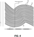
- the middle arrangement 106 shown in FIG. 1 includes S-shaped slots 124 (or gaps) made inside corresponding S-shaped occluding strips 126.
- a corresponding S-shaped optical element 128 e.g., flute
- each corresponding S-shaped optical element 128 on the back focuses collimated light received through the middle of the gap.
- the middle arrangement is able to perform designated functionality (e.g., turn functions).
- FIG. 6 is a front view of these S-shaped patterns shown from the front (from the same side as the perspective view of FIG. 1 ).
- the operation of the middle arrangement 106 is very similar to what is described for the upper arrangement 104. More specifically, the broken out magnified cross section shown in FIG. 5 would be equally accurate for a similar broken out section taken from Section 3'-3' taken from the middle arrangement 106 in FIG. 1 .
- the focal point instead of the focal point of the optical elements being a substantial circle, the focal point would be S-shaped.
- FIG. 7A reveals a view from an inside vehicle light chamber 700 where a plurality of point-focused optical elements 702 (pillow-shaped in the disclosed embodiment) are provided with a collimated source of light 703. Each of optical elements 702 is focused on a corresponding aperture in a group of apertures 704.
- the broken out view of FIG. 7B shows how these apertures 704 appear on the front of the occlusive paint 706.
- the apertures 704 are made into a substantially occlusive paint or coating 706 as the paint is being deposited onto the forward face 708 of the lens 710, could be etched out of the painted portions after painting (or coating), or could be created by numerous other methods.
- a single optical element 702a can be seen having a focal point 712 existing substantially at a center of corresponding aperture 704a.
- Each of apertures 704 are sized to be nearly invisible when viewed from a reasonable distance, and the result is that the outer overall appearance of paint 706 (coating) is one of substantial homogeneity (the visibility of the apertures is minimized). Because the light 703 introduced to the optical elements 702 is focused to pass through the apertures 704, the area in which the apertures exist will provide functional lighting for any number of applications.
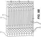
- FIG. 8A shows a diverse arrangement including both apertures and slots and flutes and pillow optical elements.
- FIG. 8B shows an opposite side of breakout portion 8B (shown in FIG. 8A ).
- the two views enable the matching up of apertures (from plurality 130) and slots (from plurality 132) with various point-focused optical elements 138 and line-focused optical elements 140 (e.g., flutes and pillows), respectively.
- a point-focused optical element 142 is focused on a center of an aperture 144 (see FIG. 8A ) in the embodiments shown ( FIGs. 1 , 2 , 8A and 8B ).
- line-focused optical elements 146 and 148 are focused on lines 150 and 152 in FIG. 8A .
- the focused light is allowed through the apertures 130 and slots 132 to allow for functional lighting, while when the light is not in use, the overall appearance appears as a solid continuous representation of the opaque finish, whatever that finish is (e.g., could be metallic).
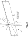
- FIG. 9 shows a cross section of an angled portion 900 of a lens which has been configured to have slots or apertures made therethrough.
- the FIG. 9 arrangement might be incorporated into the angled side of lens 110 (see FIG. 1 ).
- collimated light 902 is encountered by a plurality of optical elements 904, each of which is associated with either an aperture, slot, or some other opening 906 configured into the opaque material 908 existing on the lens.
- the optical elements 904 focus the collimated light towards a point 910 existing in the center of the opening created.
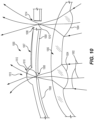
- FIG. 10 shows a cross section for an additional embodiment 1000.
- a source of collimated light 1002 is acted on by a plurality of optical elements 1004 existing on the side of an interior first lens 1005 closest to the light source (not shown).
- An outer second lens 1007 is located outside the first lens 1005 relative to the light source.
- a plurality of apertures (slots, holes) 1006 are made into an opaque coating/paint 1008 that is disposed on the interior surface 1009 of the outer lens 1007.
- the collimated light acted on by the optical elements 1004 of the first lens 1005 is focused on an area or point 1010 inside the aperture 1006.
- a plurality of optical elements 1012 further operate to control the light (e.g., create spread, diffuse, focus, etc.).
- a simple bare opening arrangement 1014 can be utilized to merely pass the light through.
- arrangement 1014 discloses the second lens material at the hole 1006 removed, it is also possible that the transparent material not be removed, but that the hole is created only by the removal of the opaque paint at that location.
- FIG. 10 embodiment shows both aperture arrangements 1013 and 1014 in the same figure, embodiments could exist where all the apertures have optical elements (e.g., like arrangement 1013), or where all of the apertures are like the one shown for the simple opening arrangement 1014.
- each of the slots, holes, and other disclosed light-allowing apertures have been chosen to allow the focused light there through, but the widths are at the same time minimized such that from a reasonable distance (or even close up in some instances), the occluded (or filtering) coating portions will appear as uniform (e.g., metalized in some embodiments; e.g., brushed aluminum) when the lamp is not illuminated. In other embodiments, the occluded (or filtered) coating portions are configured to blend into the surrounding areas of the vehicle when the lamp is off. Regardless, the arrangement appears to be substantially uniform. For slots, the widths would be the distance across the aperture. For holes, the width is herein interpreted as the diameter of the aperture.
- the widths are sized to create the desired appearance (albeit illusory) of uniformity (or homogeneity).
- the widths would be in the range of 10-250 microns. In more specific embodiments, the widths would be in the 10-100 micron range. In other embodiments, where greater uniformity is a priority, an artisan might size the widths to be less than 20 microns, a level at which apparent coating homogeneity is maintained even near vantagepoints. In some other embodiments, width sizing of about 63 microns is ideal for the purpose of conforming with an off the shelf optical element configuration. Regardless, embodiments should not be limited to any particular aperture width size unless otherwise specified in the claims.
Landscapes
- Engineering & Computer Science (AREA)
- General Engineering & Computer Science (AREA)
- Physics & Mathematics (AREA)
- Microelectronics & Electronic Packaging (AREA)
- Optics & Photonics (AREA)
- Mechanical Engineering (AREA)
- Non-Portable Lighting Devices Or Systems Thereof (AREA)
- Optical Elements Other Than Lenses (AREA)
Claims (11)
- Un système de feux arrière de véhicule comprenant :une source de lumière (204) dirigée vers un modificateur de lumière, le modificateur de lumière comprenant une pluralité d'éléments optiques (122, 128, 138, 140) sur un côté du modificateur qui fait face à la source de lumière (204), et une couverture opaque ou translucide sur un côté opposé du modificateur ;une pluralité d'ouvertures diversement configurées (112, 124, 130, 132) situées sur le côté opposé du modificateur, chaque ouverture (112, 124, 130, 132) ayant une largeur et étant formée dans le revêtement opaque ou translucide ; dans lequella pluralité d'éléments optiques (122, 128, 138, 140) est configurée pour diriger la lumière à travers chacune de la pluralité d'ouvertures diversement configurées (112, 124, 130, 132), respectivement, dans le but d'accomplir une fonction d'éclairage ; caractérisé en ce quela pluralité d'éléments optiques (122, 128, 138, 140) et les ouvertures diversement configurées (112, 124, 130, 132) comprennent divers motifs formant au moins deux arrangements différents (114, 116, 118) à différents endroits du modificateur, chaque arrangement étant configuré pour exécuter fonction désignée de feu arrière de véhicule, et en ce quela pluralité d'ouvertures diversement configurées comprend au moins une fente courbe (112, 124), et la pluralité d'éléments optiques comprend au moins une cannelure courbe (122, 128) suivant et étant centrée sur la au moins une fente courbe, la cannelure courbe étant configurée pour émettre de la lumière à travers la fente courbe.
- Le système de la revendication 1 dans lequel l'une de la pluralité d'ouvertures diversement configurées est un trou (130), et un élément optique correspondant (138) est configuré pour focaliser la lumière sur une zone ou un point dans le trou.
- Le système de la revendication 1 dans lequel :une première ouverture de la pluralité d'ouvertures diversement configurées est une fente, et un premier élément optique de la pluralité d'éléments optiques est une cannelure configurée pour focaliser la lumière à travers la fente ; etune deuxième ouverture de la pluralité d'ouvertures diversement configurées est un trou, et un deuxième élément optique de la pluralité d'éléments optiques est configuré pour focaliser la lumière à travers le trou.
- Le système de la revendication 1 dans lequel la source lumineuse (204) et le modificateur de lumière sont incorporés dans un feu de véhicule.
- Le système de la revendication 4, dans lequel le feu du véhicule est un feu de signalisation.
- Le système de la revendication 5, dans lequel la pluralité d'éléments optiques et la pluralité d'ouvertures diversement configurées permettent un premier mode, dans lequel la source de lumière est active et la lumière est transmise à travers la pluralité d'ouvertures, et un second mode sombre, dans lequel le modificateur crée une apparence solide, en particulierdans lequel l'aspect ou l'apparence solide est métallique, en particulierdont l'aspect ou l'apparence solide ressemble à de l'aluminium brossé.
- Le système de la revendication 1 dans lequel les éléments optiques (122) forment des cercles concentriques et les ouvertures (112) sont formées de cercles concentriques sur le côté opposé du modificateur.
- Le système de la revendication 7 dans lequel les éléments optiques (122) et les ouvertures (112) forment une partie supérieure d'un feu arrière, l'ouverture filtre la lumière vers la couleur rouge, et le système est configuré pour fonctionner comme un feu de freinage.
- Le système de la revendication 1 dans lequel les éléments optiques (128) et les ouvertures (124) sont en forme de S.
- Le système de la revendication 9 dans lequel les éléments optiques (128) et les ouvertures (124) forment une partie centrale de couleur jaune du système, et la partie centrale de couleur jaune est configurée pour fonctionner comme un clignotant.
- Système de la revendication 1 dans lequel la largeur des ouvertures est comprise entre 10 et 250 microns, en particulierdans lequel la largeur des ouvertures est comprise entre 10 et 100 microns, en particulierdans lequel les ouvertures ont une largeur inférieure à 20 microns ou d'environ 63 microns.
Applications Claiming Priority (2)
| Application Number | Priority Date | Filing Date | Title |
|---|---|---|---|
| US202062972309P | 2020-02-10 | 2020-02-10 | |
| PCT/IB2021/000071 WO2021161098A1 (fr) | 2020-02-10 | 2021-02-10 | Système fournissant un éclairage fonctionnel à travers une finition opaque |
Publications (3)
| Publication Number | Publication Date |
|---|---|
| EP4103879A1 EP4103879A1 (fr) | 2022-12-21 |
| EP4103879A4 EP4103879A4 (fr) | 2023-08-23 |
| EP4103879B1 true EP4103879B1 (fr) | 2025-04-30 |
Family
ID=77177401
Family Applications (1)
| Application Number | Title | Priority Date | Filing Date |
|---|---|---|---|
| EP21754555.7A Active EP4103879B1 (fr) | 2020-02-10 | 2021-02-10 | Système fournissant un éclairage fonctionnel à travers une finition opaque |
Country Status (4)
| Country | Link |
|---|---|
| US (1) | US11421848B2 (fr) |
| EP (1) | EP4103879B1 (fr) |
| ES (1) | ES3035919T3 (fr) |
| WO (1) | WO2021161098A1 (fr) |
Families Citing this family (2)
| Publication number | Priority date | Publication date | Assignee | Title |
|---|---|---|---|---|
| US11774073B1 (en) | 2022-10-28 | 2023-10-03 | Xiaohong Chen | Foldable clamp-on desk lamp with multi-angle adjustment function |
| FR3153397A1 (fr) * | 2023-09-25 | 2025-03-28 | Flex-N-Gate France | Dispositif lumineux pour véhicule |
Family Cites Families (17)
| Publication number | Priority date | Publication date | Assignee | Title |
|---|---|---|---|---|
| US3487206A (en) * | 1967-04-10 | 1969-12-30 | Ford Motor Co | Concealed vehicle running light assembly |
| GB1591013A (en) * | 1978-05-30 | 1981-06-10 | Lucas Industries Ltd | High contrast lamp assembly |
| EP0081361A1 (fr) | 1981-12-08 | 1983-06-15 | LUCAS INDUSTRIES public limited company | Feu |
| GB8327529D0 (en) * | 1983-10-14 | 1983-11-16 | Lucas Ind Plc | Indiscernible lamp |
| DE3636383A1 (de) | 1986-10-25 | 1988-04-28 | Swf Auto Electric Gmbh | Signalleuchte, insbesondere fuer kraftfahrzeuge |
| JP2507834B2 (ja) | 1991-02-08 | 1996-06-19 | 株式会社小糸製作所 | 投射型自動車用ヘッドランプ |
| FR2680862B1 (fr) * | 1991-09-02 | 1997-08-08 | Valeo Vision | Feu de signalisation a elements electroluminescents, notamment pour vehicule automobile. |
| DE4228928C1 (de) | 1992-08-31 | 1993-12-16 | Swf Auto Electric Gmbh | Signalleuchte |
| FR2763385B1 (fr) | 1997-05-15 | 1999-08-06 | Valeo Vision | Feu de signalisation pour vehicule automobile a synthese additive |
| DE19753762A1 (de) | 1997-12-04 | 1999-06-10 | Itt Mfg Enterprises Inc | Signalleuchte, insbesondere Kombinationsheckleuchte eines Fahrzeuges |
| FR2776595B1 (fr) * | 1998-03-31 | 2000-06-16 | Valeo Vision | Feu de signalisation comprenant plusieurs sources lumineuses |
| GB2417790B (en) | 2004-09-07 | 2006-11-08 | Set Europ Ltd | Lighting system |
| EP2347170A4 (fr) | 2008-11-06 | 2017-12-27 | Innovations in Optics, Inc. | Module d'eclairage de secours a diodes electroluminescentes |
| JP2018526663A (ja) * | 2015-06-02 | 2018-09-13 | コーニング インコーポレイテッド | 美観表面およびそのような表面を有する表示装置 |
| FR3045781B1 (fr) | 2015-12-18 | 2020-03-06 | Valeo Vision Belgique | Module lumineux, notamment pour feu stop sureleve avec aspect lisse |
| WO2019158890A1 (fr) | 2018-02-19 | 2019-08-22 | Automotive Lighting Rear Lamps France | Dispositif de signalisation pour véhicule automobile comprenant un écran opaque permettant le passage d'une plus grande quantité de lumière émise par une source de lumière dissimulée derrière ledit écran |
| DE102018002721B4 (de) | 2018-04-05 | 2022-03-10 | Daimler Ag | Beleuchtungsvorrichtung für ein Fahrzeug |
-
2021
- 2021-02-10 EP EP21754555.7A patent/EP4103879B1/fr active Active
- 2021-02-10 US US17/172,656 patent/US11421848B2/en active Active
- 2021-02-10 WO PCT/IB2021/000071 patent/WO2021161098A1/fr not_active Ceased
- 2021-02-10 ES ES21754555T patent/ES3035919T3/es active Active
Also Published As
| Publication number | Publication date |
|---|---|
| US11421848B2 (en) | 2022-08-23 |
| US20210247045A1 (en) | 2021-08-12 |
| ES3035919T3 (en) | 2025-09-11 |
| EP4103879A4 (fr) | 2023-08-23 |
| EP4103879A1 (fr) | 2022-12-21 |
| WO2021161098A1 (fr) | 2021-08-19 |
Similar Documents
| Publication | Publication Date | Title |
|---|---|---|
| US6296382B1 (en) | Multi-chamber lamp for vehicles | |
| EP4034421B1 (fr) | Source de lumière comprenant des lentilles multicouches modifiées | |
| US4989967A (en) | Lens for spectacles | |
| CN112585031B (zh) | 具有衍射光学元件的机动车大灯 | |
| US11421848B2 (en) | System providing functional lighting through an opaque finish | |
| JPH08500463A (ja) | シグナルランプ | |
| US6264347B1 (en) | Indicating light with homogeneous illumination, including smooth zones | |
| US20080030990A1 (en) | Lighting System Comprising a Mask with Small Apertures | |
| US11435049B2 (en) | Light device of a motor vehicle | |
| WO2018168188A1 (fr) | Panneau d'affichage | |
| EP3237798A1 (fr) | Élément de carrosserie de véhicule comprenant un corps translucide et procédé de production d'un tel corps | |
| EP2181458B1 (fr) | Appareil et procédé pour augmenter la visibilité de signal | |
| KR102882487B1 (ko) | 차량용 가니시리스 히든 램프 | |
| US20160046239A1 (en) | Rearview mirror with selective refelction and method of manufacture | |
| US10578269B2 (en) | Partial metallization of light guides for a binary aesthetic | |
| US10760764B2 (en) | Partial metallization of molded part using ablation | |
| CN216546032U (zh) | 车辆内部装饰部件 | |
| JP2025011556A (ja) | 車両用外装品 | |
| US20240356207A1 (en) | System for backlighting a radome and radar device | |
| JP7541568B2 (ja) | 光アセンブリを含む車両意匠要素 | |
| KR101959802B1 (ko) | 차량용 램프의 베젤 | |
| EP3620714B1 (fr) | Dispositif d'éclairage et/ou de signalisation automobile | |
| US20250196762A1 (en) | Optical component with micro-optical features | |
| KR20150010308A (ko) | 차량용 램프 | |
| JP2019096462A (ja) | 樹脂成形品および車両用灯具 |
Legal Events
| Date | Code | Title | Description |
|---|---|---|---|
| STAA | Information on the status of an ep patent application or granted ep patent |
Free format text: STATUS: THE INTERNATIONAL PUBLICATION HAS BEEN MADE |
|
| PUAI | Public reference made under article 153(3) epc to a published international application that has entered the european phase |
Free format text: ORIGINAL CODE: 0009012 |
|
| STAA | Information on the status of an ep patent application or granted ep patent |
Free format text: STATUS: REQUEST FOR EXAMINATION WAS MADE |
|
| 17P | Request for examination filed |
Effective date: 20220909 |
|
| AK | Designated contracting states |
Kind code of ref document: A1 Designated state(s): AL AT BE BG CH CY CZ DE DK EE ES FI FR GB GR HR HU IE IS IT LI LT LU LV MC MK MT NL NO PL PT RO RS SE SI SK SM TR |
|
| DAV | Request for validation of the european patent (deleted) | ||
| DAX | Request for extension of the european patent (deleted) | ||
| A4 | Supplementary search report drawn up and despatched |
Effective date: 20230724 |
|
| RIC1 | Information provided on ipc code assigned before grant |
Ipc: F21V 5/00 20180101ALI20230718BHEP Ipc: F21S 41/20 20180101ALI20230718BHEP Ipc: B60Q 1/26 20060101ALI20230718BHEP Ipc: F21S 43/20 20180101AFI20230718BHEP |
|
| STAA | Information on the status of an ep patent application or granted ep patent |
Free format text: STATUS: EXAMINATION IS IN PROGRESS |
|
| 17Q | First examination report despatched |
Effective date: 20240426 |
|
| GRAP | Despatch of communication of intention to grant a patent |
Free format text: ORIGINAL CODE: EPIDOSNIGR1 |
|
| STAA | Information on the status of an ep patent application or granted ep patent |
Free format text: STATUS: GRANT OF PATENT IS INTENDED |
|
| INTG | Intention to grant announced |
Effective date: 20241129 |
|
| GRAS | Grant fee paid |
Free format text: ORIGINAL CODE: EPIDOSNIGR3 |
|
| GRAA | (expected) grant |
Free format text: ORIGINAL CODE: 0009210 |
|
| STAA | Information on the status of an ep patent application or granted ep patent |
Free format text: STATUS: THE PATENT HAS BEEN GRANTED |
|
| AK | Designated contracting states |
Kind code of ref document: B1 Designated state(s): AL AT BE BG CH CY CZ DE DK EE ES FI FR GB GR HR HU IE IS IT LI LT LU LV MC MK MT NL NO PL PT RO RS SE SI SK SM TR |
|
| REG | Reference to a national code |
Ref country code: CH Ref legal event code: EP Ref country code: GB Ref legal event code: FG4D |
|
| REG | Reference to a national code |
Ref country code: IE Ref legal event code: FG4D |
|
| REG | Reference to a national code |
Ref country code: DE Ref legal event code: R096 Ref document number: 602021030046 Country of ref document: DE |
|
| REG | Reference to a national code |
Ref country code: NL Ref legal event code: MP Effective date: 20250430 |
|
| REG | Reference to a national code |
Ref country code: ES Ref legal event code: FG2A Ref document number: 3035919 Country of ref document: ES Kind code of ref document: T3 Effective date: 20250911 |
|
| REG | Reference to a national code |
Ref country code: AT Ref legal event code: MK05 Ref document number: 1790304 Country of ref document: AT Kind code of ref document: T Effective date: 20250430 |
|
| PG25 | Lapsed in a contracting state [announced via postgrant information from national office to epo] |
Ref country code: PT Free format text: LAPSE BECAUSE OF FAILURE TO SUBMIT A TRANSLATION OF THE DESCRIPTION OR TO PAY THE FEE WITHIN THE PRESCRIBED TIME-LIMIT Effective date: 20250901 Ref country code: FI Free format text: LAPSE BECAUSE OF FAILURE TO SUBMIT A TRANSLATION OF THE DESCRIPTION OR TO PAY THE FEE WITHIN THE PRESCRIBED TIME-LIMIT Effective date: 20250430 |
|
| REG | Reference to a national code |
Ref country code: LT Ref legal event code: MG9D |
|
| PG25 | Lapsed in a contracting state [announced via postgrant information from national office to epo] |
Ref country code: GR Free format text: LAPSE BECAUSE OF FAILURE TO SUBMIT A TRANSLATION OF THE DESCRIPTION OR TO PAY THE FEE WITHIN THE PRESCRIBED TIME-LIMIT Effective date: 20250731 Ref country code: NO Free format text: LAPSE BECAUSE OF FAILURE TO SUBMIT A TRANSLATION OF THE DESCRIPTION OR TO PAY THE FEE WITHIN THE PRESCRIBED TIME-LIMIT Effective date: 20250730 |
|
| PG25 | Lapsed in a contracting state [announced via postgrant information from national office to epo] |
Ref country code: NL Free format text: LAPSE BECAUSE OF FAILURE TO SUBMIT A TRANSLATION OF THE DESCRIPTION OR TO PAY THE FEE WITHIN THE PRESCRIBED TIME-LIMIT Effective date: 20250430 Ref country code: PL Free format text: LAPSE BECAUSE OF FAILURE TO SUBMIT A TRANSLATION OF THE DESCRIPTION OR TO PAY THE FEE WITHIN THE PRESCRIBED TIME-LIMIT Effective date: 20250430 |
|
| PG25 | Lapsed in a contracting state [announced via postgrant information from national office to epo] |
Ref country code: BG Free format text: LAPSE BECAUSE OF FAILURE TO SUBMIT A TRANSLATION OF THE DESCRIPTION OR TO PAY THE FEE WITHIN THE PRESCRIBED TIME-LIMIT Effective date: 20250430 |
|
| PG25 | Lapsed in a contracting state [announced via postgrant information from national office to epo] |
Ref country code: HR Free format text: LAPSE BECAUSE OF FAILURE TO SUBMIT A TRANSLATION OF THE DESCRIPTION OR TO PAY THE FEE WITHIN THE PRESCRIBED TIME-LIMIT Effective date: 20250430 |
|
| PG25 | Lapsed in a contracting state [announced via postgrant information from national office to epo] |
Ref country code: AT Free format text: LAPSE BECAUSE OF FAILURE TO SUBMIT A TRANSLATION OF THE DESCRIPTION OR TO PAY THE FEE WITHIN THE PRESCRIBED TIME-LIMIT Effective date: 20250430 |
|
| PG25 | Lapsed in a contracting state [announced via postgrant information from national office to epo] |
Ref country code: RS Free format text: LAPSE BECAUSE OF FAILURE TO SUBMIT A TRANSLATION OF THE DESCRIPTION OR TO PAY THE FEE WITHIN THE PRESCRIBED TIME-LIMIT Effective date: 20250731 |
|
| PG25 | Lapsed in a contracting state [announced via postgrant information from national office to epo] |
Ref country code: IS Free format text: LAPSE BECAUSE OF FAILURE TO SUBMIT A TRANSLATION OF THE DESCRIPTION OR TO PAY THE FEE WITHIN THE PRESCRIBED TIME-LIMIT Effective date: 20250830 |
|
| PG25 | Lapsed in a contracting state [announced via postgrant information from national office to epo] |
Ref country code: LV Free format text: LAPSE BECAUSE OF FAILURE TO SUBMIT A TRANSLATION OF THE DESCRIPTION OR TO PAY THE FEE WITHIN THE PRESCRIBED TIME-LIMIT Effective date: 20250430 |
|
| PG25 | Lapsed in a contracting state [announced via postgrant information from national office to epo] |
Ref country code: DK Free format text: LAPSE BECAUSE OF FAILURE TO SUBMIT A TRANSLATION OF THE DESCRIPTION OR TO PAY THE FEE WITHIN THE PRESCRIBED TIME-LIMIT Effective date: 20250430 Ref country code: SM Free format text: LAPSE BECAUSE OF FAILURE TO SUBMIT A TRANSLATION OF THE DESCRIPTION OR TO PAY THE FEE WITHIN THE PRESCRIBED TIME-LIMIT Effective date: 20250430 |
|
| PG25 | Lapsed in a contracting state [announced via postgrant information from national office to epo] |
Ref country code: CZ Free format text: LAPSE BECAUSE OF FAILURE TO SUBMIT A TRANSLATION OF THE DESCRIPTION OR TO PAY THE FEE WITHIN THE PRESCRIBED TIME-LIMIT Effective date: 20250430 |
|
| PG25 | Lapsed in a contracting state [announced via postgrant information from national office to epo] |
Ref country code: EE Free format text: LAPSE BECAUSE OF FAILURE TO SUBMIT A TRANSLATION OF THE DESCRIPTION OR TO PAY THE FEE WITHIN THE PRESCRIBED TIME-LIMIT Effective date: 20250430 |
|
| PG25 | Lapsed in a contracting state [announced via postgrant information from national office to epo] |
Ref country code: SK Free format text: LAPSE BECAUSE OF FAILURE TO SUBMIT A TRANSLATION OF THE DESCRIPTION OR TO PAY THE FEE WITHIN THE PRESCRIBED TIME-LIMIT Effective date: 20250430 |
|
| PG25 | Lapsed in a contracting state [announced via postgrant information from national office to epo] |
Ref country code: IT Free format text: LAPSE BECAUSE OF FAILURE TO SUBMIT A TRANSLATION OF THE DESCRIPTION OR TO PAY THE FEE WITHIN THE PRESCRIBED TIME-LIMIT Effective date: 20250430 |
|
| REG | Reference to a national code |
Ref country code: DE Ref legal event code: R097 Ref document number: 602021030046 Country of ref document: DE |
|
| PLBE | No opposition filed within time limit |
Free format text: ORIGINAL CODE: 0009261 |
|
| STAA | Information on the status of an ep patent application or granted ep patent |
Free format text: STATUS: NO OPPOSITION FILED WITHIN TIME LIMIT |
|
| REG | Reference to a national code |
Ref country code: CH Ref legal event code: L10 Free format text: ST27 STATUS EVENT CODE: U-0-0-L10-L00 (AS PROVIDED BY THE NATIONAL OFFICE) Effective date: 20260311 |
|
| 26N | No opposition filed |
Effective date: 20260202 |
|
| PGFP | Annual fee paid to national office [announced via postgrant information from national office to epo] |
Ref country code: GB Payment date: 20260218 Year of fee payment: 6 |
|
| PGFP | Annual fee paid to national office [announced via postgrant information from national office to epo] |
Ref country code: ES Payment date: 20260303 Year of fee payment: 6 |
|
| PGFP | Annual fee paid to national office [announced via postgrant information from national office to epo] |
Ref country code: DE Payment date: 20260217 Year of fee payment: 6 |
|
| PGFP | Annual fee paid to national office [announced via postgrant information from national office to epo] |
Ref country code: FR Payment date: 20260218 Year of fee payment: 6 |