EP4104420B1 - Procédé et dispositif coordinateur pour la mise en sélective d'un dispositif de noeud dans un réseau - Google Patents
Procédé et dispositif coordinateur pour la mise en sélective d'un dispositif de noeud dans un réseau Download PDFInfo
- Publication number
- EP4104420B1 EP4104420B1 EP21703463.6A EP21703463A EP4104420B1 EP 4104420 B1 EP4104420 B1 EP 4104420B1 EP 21703463 A EP21703463 A EP 21703463A EP 4104420 B1 EP4104420 B1 EP 4104420B1
- Authority
- EP
- European Patent Office
- Prior art keywords
- coordinator
- node
- network
- coordinator device
- commissioning
- Prior art date
- Legal status (The legal status is an assumption and is not a legal conclusion. Google has not performed a legal analysis and makes no representation as to the accuracy of the status listed.)
- Active
Links
Images


Classifications
-
- H—ELECTRICITY
- H04—ELECTRIC COMMUNICATION TECHNIQUE
- H04L—TRANSMISSION OF DIGITAL INFORMATION, e.g. TELEGRAPHIC COMMUNICATION
- H04L12/00—Data switching networks
- H04L12/02—Details
- H04L12/12—Arrangements for remote connection or disconnection of substations or of equipment thereof
-
- H—ELECTRICITY
- H04—ELECTRIC COMMUNICATION TECHNIQUE
- H04L—TRANSMISSION OF DIGITAL INFORMATION, e.g. TELEGRAPHIC COMMUNICATION
- H04L67/00—Network arrangements or protocols for supporting network services or applications
- H04L67/01—Protocols
- H04L67/12—Protocols specially adapted for proprietary or special-purpose networking environments, e.g. medical networks, sensor networks, networks in vehicles or remote metering networks
- H04L67/125—Protocols specially adapted for proprietary or special-purpose networking environments, e.g. medical networks, sensor networks, networks in vehicles or remote metering networks involving control of end-device applications over a network
-
- H—ELECTRICITY
- H05—ELECTRIC TECHNIQUES NOT OTHERWISE PROVIDED FOR
- H05B—ELECTRIC HEATING; ELECTRIC LIGHT SOURCES NOT OTHERWISE PROVIDED FOR; CIRCUIT ARRANGEMENTS FOR ELECTRIC LIGHT SOURCES, IN GENERAL
- H05B47/00—Circuit arrangements for operating light sources in general, i.e. where the type of light source is not relevant
- H05B47/10—Controlling the light source
- H05B47/175—Controlling the light source by remote control
- H05B47/19—Controlling the light source by remote control via wireless transmission
-
- H—ELECTRICITY
- H05—ELECTRIC TECHNIQUES NOT OTHERWISE PROVIDED FOR
- H05B—ELECTRIC HEATING; ELECTRIC LIGHT SOURCES NOT OTHERWISE PROVIDED FOR; CIRCUIT ARRANGEMENTS FOR ELECTRIC LIGHT SOURCES, IN GENERAL
- H05B47/00—Circuit arrangements for operating light sources in general, i.e. where the type of light source is not relevant
- H05B47/10—Controlling the light source
- H05B47/175—Controlling the light source by remote control
- H05B47/198—Grouping of control procedures or address assignation to light sources
- H05B47/199—Commissioning of light sources
- H05B47/1995—Auto-commissioning
-
- H—ELECTRICITY
- H04—ELECTRIC COMMUNICATION TECHNIQUE
- H04W—WIRELESS COMMUNICATION NETWORKS
- H04W24/00—Supervisory, monitoring or testing arrangements
- H04W24/02—Arrangements for optimising operational condition
-
- H—ELECTRICITY
- H04—ELECTRIC COMMUNICATION TECHNIQUE
- H04W—WIRELESS COMMUNICATION NETWORKS
- H04W84/00—Network topologies
- H04W84/18—Self-organising networks, e.g. ad-hoc networks or sensor networks
-
- Y—GENERAL TAGGING OF NEW TECHNOLOGICAL DEVELOPMENTS; GENERAL TAGGING OF CROSS-SECTIONAL TECHNOLOGIES SPANNING OVER SEVERAL SECTIONS OF THE IPC; TECHNICAL SUBJECTS COVERED BY FORMER USPC CROSS-REFERENCE ART COLLECTIONS [XRACs] AND DIGESTS
- Y02—TECHNOLOGIES OR APPLICATIONS FOR MITIGATION OR ADAPTATION AGAINST CLIMATE CHANGE
- Y02D—CLIMATE CHANGE MITIGATION TECHNOLOGIES IN INFORMATION AND COMMUNICATION TECHNOLOGIES [ICT], I.E. INFORMATION AND COMMUNICATION TECHNOLOGIES AIMING AT THE REDUCTION OF THEIR OWN ENERGY USE
- Y02D30/00—Reducing energy consumption in communication networks
- Y02D30/50—Reducing energy consumption in communication networks in wire-line communication networks, e.g. low power modes or reduced link rate
Definitions
- the present disclosure generally relates to the field of managing node devices of a network, and, more specifically, to a method of and a coordinator device for selectively commissioning a node device in a network.
- Electric or electronic devices such as lighting devices and Internet of Things, loT, devices, and devices supporting enhanced Machine-Type Communication, eMTC, for example, all of which comprise data communication capabilities, are frequently deployed in networks comprised of a plurality of interconnected devices.
- node devices may comprise a communication interface, such as a network adapter or transceiver module, for communication between node devices and possibly also with remote devices, such as a backend device or backend server.
- a communication interface such as a network adapter or transceiver module
- the communication interface may operate in accordance with a network protocol for exchanging data by networked devices or nodes, such as designated ZigBee TM , Bluetooth TM , as well as WiFi based protocols for wireless networks, and wired bus networks such as DALI TM (Digital Addressable Lighting Interface), DSI (Digital Serial Interface), DMX (Digital Multiplex), KNX (and KNX based systems), and proprietary communication technologies and protocols, for example.
- a network protocol for exchanging data by networked devices or nodes such as designated ZigBee TM , Bluetooth TM , as well as WiFi based protocols for wireless networks, and wired bus networks such as DALI TM (Digital Addressable Lighting Interface), DSI (Digital Serial Interface), DMX (Digital Multiplex), KNX (and KNX based systems), and proprietary communication technologies and protocols, for example.
- DALI TM Digital Addressable Lighting Interface
- DSI Digital Serial Interface
- DMX Digital Multiplex
- KNX and KNX based systems
- the communication interface may further operate in accordance with a wireless mobile communication standard, such as designated 2G/3G/4G/5G cellular communication, and other long-range wireless communication technologies like Long Range Wide Area Network, LoRaWAN, and Narrowband IoT, NB-loT, or proprietary communication technologies, and/or a wired data exchange communication technology, for example.
- a wireless mobile communication standard such as designated 2G/3G/4G/5G cellular communication
- other long-range wireless communication technologies like Long Range Wide Area Network, LoRaWAN, and Narrowband IoT, NB-loT, or proprietary communication technologies, and/or a wired data exchange communication technology, for example.
- loT node devices such as ZigBee node devices
- commissioning is the first step to establish a wireless loT network.
- a commissioning process is generally open in the sense that a ZigBee coordinator device can join or pull or collect any node device into its network, as long as these node devices are searching for a network to join at a point of time when the network created by the coordinator device is available to join.
- node devices When more than one coordinator devices belonging to different networks perform network join actions simultaneously, node devices will join the available networks randomly. In this case, it is even easier for a node device to join a wrong network, which will cause problems in network connectivity and create operation confliction.
- a way of ensuring that only a specified group of node devices will join a specific network is to have the coordinator device store identifiers of node devices allowed to join the network of the coordinator device.
- This approach however imposes extra storage burden to the coordinator device and needs a lot of manual effort to input the identifiers of the node devices into the storage means. Besides, such an approach is essentially impractical for real applications due to uncertainty associated with expected nodes in a specific network.
- US2016248629A1 discloses a commissioning tool able to configure and commission devices belonging to different ZigBee public profiles.
- XBee /XBee-PRO S2C Zigbee RF module proposes to prevent unwanted devices from joining when a new device is needed to be added to a network by enabling permit-joining for a short time on the network.
- US2010150063A1 relates to Zigbee joining process for reducing the possibility of joining an unanticipated node by using a time window during which coordinator allows nodes to join in.
- US2016142263A1 relates to a wireless node and to a method for operating the wireless node, wherein the wireless node comprises a controller arranged for communicating wirelessly with at least one further wireless node so as to determine an ability of the wireless node and to create a network, wherein a characteristic of the network depends on the ability of the wireless node.
- the present disclosure is based on the insight that a time-based selective commissioning method can be used to ensure that a node device will join a correct or appropriate or intended network created by a coordinator device.
- the coordinator temporal indication and the node device temporal indication comprise the commissioning start time of coordinator and node device respectively.
- the solution in accordance with one embodiment of the present disclosure relies on checking, by the coordinator device, that commissioning start times respectively recorded by the coordinator device and the node device and respectively relating to powered-up time of the coordinator device and the node device are the same or temporally very similar or close to each other.
- the temporal proximity or equality between the powering up times of the coordinator device and the node device helps to ensure that the network created by the coordinator device is the correct network for the node device to join. This is based on the scenario that the coordinator device and node devices start to commissioning once they are powered up.
- the method of the present disclosure is especially advantageous when the coordinator device together with the node device perform a twofold check to determine that the coordinator device and the node device are powered up simultaneously or that the node device is powered up very soon after the powering up of the coordinator device.
- the joining request is transmitted by the node device in response to determining that the coordinator temporal indication matches the node temporal indication.
- the coordinator device first transmits a network-available message indicating the availability of the network created by the coordinator device.
- the network-available message comprises a coordinator temporal indication related to the commissioning start time of the coordinator device.
- the node device Upon receiving the network-available message, the node device transmits a joining request to the coordinator device, requesting to join the network created by the coordinator device.
- the transmission of the joining request may specially depend on the node device deciding that the coordinator temporal indication matches the node temporal indication related to the commissioning start time of the node device.
- the coordinator device (once again) determines and confirms that the coordinator temporal indication and the node temporal indication match each other, this is to decide that the commissioning start times of both the coordinator device and the node device are the same or very similar to each other. After that, the coordinator device commissions the node device by joining it into the network.
- the method of the present disclosure therefore performs a bi-directional check of the commissioning start times of both the coordinator device and the node device and allows the node device to join the network created or owned by the coordinator device only when the coordinator temporal indication and the node temporal indication respectively related to the commissioning start time of the coordinator device and the node device match each other.
- This twofold check guarantees that the network will only have node devices switched on at the same time or after the powering up of the coordinator device join the network, and that no other node device such as node devices powered up already for a while before the powering up of the coordinator device will accidently or wrongly join the network.
- the method does not require extra storage by the coordinator device for storing identifiers of node devices allowed to join the network, this is advantageous, especially considering that the coordinator device normally does not have strong storage capacity.
- the selective commissioning is essentially realised by switching on the coordinator device and the node device at the same time, which is straightforward and easy to control, and does not require special control instructions.
- the step of transmitting comprises broadcasting, by the coordinator device, a beacon message indicating availability of the network as the network-available message.
- a node device seeking to join a network can operate in a so-called passive scan mode, that is, the node device just listens and waits for the beacon message, which is the network available message, indicating presence or availability of the network created by the coordinator device. Receiving such as a beacon message allows the node device to check and decide if the network is the correct network to join.
- the coordinator device more flexibility in controlling the time when node devices are allowed to join the network. Specifically, when the coordinator device is switched on before the node device, it can get ready to create the network, and then send a message or instruction or an induction to have the node devices that are supposed and allowed to join the network switched on or powered up. Then the coordinator device broadcasts the beacon message, inviting the node devices to join the network.
- the step of transmitting comprises transmitting, by the coordinator device, in response to receiving a beacon request message from the node device, a beacon response message indicating availability of the network as the network-available message.
- a node device seeking to join a network operates in a so-called active scan mode.
- the node device sends a beacon request message, requesting to join a network.
- the coordinator device Upon receiving the beacon request message, the coordinator device transmits a beacon message, that is, a beacon response message, to the node device.
- the beacon response message comprises the coordinator temporal indication related to the commissioning start time of the coordinator device.
- the node device checks and decides if the network is the correct network to join by checking if the coordinator temporal indication matches the node temporal indication.
- the above interaction procedure between the coordinator device and the node device is easy to implement, especially for the scenario when the coordinator device and the node device are powered up at the same time.
- the node device actively searching for the available network can help to improve the overall commissioning efficiency.
- the step of determining the coordinator temporal indication matches the node temporal indication comprises the steps of:
- the coordinator device checks to see if the two devices start commissioning at about the same time. This is realised by calculating the time difference between the commissioning start time of the coordinator device and the commissioning start time of the node device and deciding that a match is present when the time difference is smaller than a predefined threshold value, such as 10 seconds.
- the node device decides that the coordinator indication matches the node indication in a similar way.
- Such a determination step involves a simple arithmetic operation and comparison and can be performed by the coordinator device easily without requiring much computational resource.
- the coordinator temporal indication related to the commissioning start time of the coordinator device comprises a first elapsed time from the coordinator device being powered up to the network-available message being transmitted by the coordinator device
- the node temporal indication related to the commissioning start time of the node device comprises a second elapsed time from the node device being powered up to the joining request being transmitted by the node device
- the step of calculating comprises calculating a time difference between the first elapsed time and the second elapsed time.
- the coordinator temporal indication and the node temporal indicate are both relative times calculated to respectively indicate the commissioning start time of the coordinator device and the node device. This approach is generally applicable to various scenarios, independent of whether the coordinator device and the node device are synchronised and/or powered up at the same time, or not.
- the commissioning start time is calculated as an elapsed time, from when the coordinator device transmitting a ready message indicating that commissioning has started, to when the network-available message is transmitted by the coordinator device. Whether the node device is started the same time as or later than the coordinator device, its commissioning start time will be calculated simply from the powering up of the node device to when the joining request is transmitted by the node device.
- Using the relative time as the temporal indication is advantageous in that possible deviation in, for example, system times of the coordinator device and the node device may be offset, which helps to ensure accurate implementation of the method.
- using the absolute time as the temporal indication is also easy and straightforward.
- the coordinator device and the node device are synchronized and powered up at substantially the same time
- the coordinator temporal indication related to the commissioning start time of the coordinator device comprises a first time when the coordinator device is powered up
- the node temporal indication related to the commissioning start time of the node device comprises a second time when the node device is powered up
- the step of calculating comprises calculating a time difference between the first time and the second time.
- the coordinator and node temporal indications can be an absolute time.
- the absolute time may be equivalent to a powering up time of the coordinator or node device.
- the determination step is even more straightforward as it involves simple and arithmetic calculation of recorded powering up time of both devices.
- the transmitted message further comprises a flag generated by the coordinator device within a time window subsequent to creation of the network, the joining request further comprises the flag.
- the coordinator device As a supplementary measure for ensuring that the coordinator device and the node device can determine that their commissioning start time are the same or very similar to each other, the coordinator device generates, within a time window such as a short period of time after the creation of the network by the coordinator device, a limited number of flags.
- the coordinator device further has one flag included in each network-available message transmitted within the short period of time therefore comprises such a flag.
- a flag may be a random number. As the number of flags is limited, a number of transmitted network-available message comprising a flag is also limited. Only node devices powered up within this short period of time will receive a network-available message together with a flag. Therefore, the node device can decide that it is powered up at a time essentially the same as the coordinator device, if the network-available message received by the node device includes such a flag.
- the node device upon receiving the network-available message comprising the flag, first determines that the coordinator temporal indication matches the node temporal indication, and then checks to see that the flag is present. By this means, the node device confirms by two different criteria that the commissioning start time of the coordinator device is the same or very similar to its own commissioning start time. In transmitting the joining request, the node device also includes the received flag in the joining request.
- the step of determining that the coordinator temporal indication matches the node temporal indication further comprises determining that the flag matches one of the plurality of flags transmitted by the coordinator device.
- the coordinator device decides that the node device is acceptable to join the network if the flag comprised in the joining request from the node device is a flag previously generated and transmitted. This is an extra measure of preventing the coordinator device from drawing unwanted or undesired node devices into its network.
- the network-available message is transmitted to node devices within a limited number of hops away from the coordinator device.
- the transmission of the network-available message is limited to node devices two hops away from the coordinator device, which means the network-available message will be discarded, if the node device receiving the network-available message is further than two hops away, thereby avoiding the unnecessary transmission to a larger field.
- each of the coordinator device and the node device operating a Medium Access Control, MAC, data processing protocol sub-layer, wherein the coordinator temporal indication and the node temporal indication are respectively comprised in MAC transmission offset field of the network-available message and the joining request.
- the MAC sub-layer is part of the data link layer defined by the Open System Interconnections, OSI, model that conceptualizes how communications data should be processed between systems.
- the network-available message comprising the coordinator temporal indication and the joining request comprising the node temporal indication
- transmitted as MAC sub-layer message has the advantage of reducing traffic in a wireless channel that the network operates on.
- the step of determining is performed by the MAC data processing protocol sub-layer.
- Transmission of a message from a source device to a destination device in a network normally involves the MAC sub-layer and/or the network layer.
- the network layer usually relies on the MAC sub-layer broadcast to transfer the message from the source device to the destination device. That is, the message usually does not go to the network layer for data processing if the message propagates in the same network.
- the implementation, in the MAC layer, of determining that the coordinator temporal indication matches the node temporal indication is more efficient in terms of usage of computational resources. Overall, better performance is achieved by performing the determination at the lower MAC sub-layer.
- a second aspect of the present disclosure provides a coordinator device arranged for selectively commissioning a node device in a network created by the coordinator device based on the method according to the first aspect of the present disclosure.
- a third aspect of the present disclosure provides a node device arranged for being selectively commissioned based on the method according to the first aspect of the present disclosure.
- the node device comprises a lighting fixture.
- the method of the present disclosure can be advantageously used to configure or commission a large number of node devices comprising lighting fixtures, such as lighting features in a building or a stadium.
- a computer program product comprising a computer readable storage medium storing instructions which, when executed on at least one processor, cause the at least one processor to carry out the method according to the first aspect of the present disclosure.
- the present disclosure is detailed below with reference to lighting devices functioning as node devices of a network created by a coordinator device commissioning the lighting devices in the network. Those skilled in the art will appreciate that the present disclosure is not limited to commissioning a network of lighting devices, but is applicable for networks of a wide variety of node devices enabled with network communication connectivity, as indicated in the background part.
- Figure 1 schematically illustrates a diagram 100 of two coordinator devices 10 and 20 configuring a plurality of node devices 11-18 and 21-27.
- the coordinator devices 10 and 20 operate to commission the node devices, that is, the lighting devices, 11-18 and 21-27, by joining the node devices into the networks 19, 29.
- the node devices that is, the lighting devices, 11-18 and 21-27
- a method of selectively commissioning node devices by a coordinator device which will be detailed in the following, will provide a solution for obviating the above problems.
- Figure 2 schematically illustrates, in a flow chart type diagram, exemplary steps of a method 30 of creating a network by a coordinator device in accordance with an embodiment of the present disclosure.
- a coordinator device such as a dongle or a modem operating as a ZigBee coordinator, is a device that can start or create a network and is responsible for selecting a channel, a Personal Area Network identifier, a PAN ID, a security policy, and a stack profile for the network. After the coordinator device has started the network, it may allow raw devices, such as node devices or terminal devices, to join the network.
- the coordinator device after the coordinator device is powered up and before it creates a new network, at step 31 "coordinator scanning channels", the coordinator device, such as the coordinator device 10 of Figure 1 , scans all channels, to discover, at step 32 "network existing?", any possible existing network that is created by a different coordinator device.
- the existing network is open for node devices to join.
- coordinator devices 10 If the coordinator devices 10 does not find any open or existing network at step 32, it proceeds to step 35 "coordinator creating a new network", to create a new network.
- the coordinator device 10 may send a ready message to a mobile phone of a field engineer or technician or turn on an optical indictor to indicate to the field engineer or technician that the node devices can be powered up.
- the coordinator device 10 may also send a relay drive message to power up the node devices 11-18.
- the coordinator device 10 then creates a new network 19.
- the coordinator device 10 If the coordinator device 10 receives a beacon message of a network joining permit in a certain channel, that is, it is determined at step 32 there is already a network open and available for the node devices to join, such as the network 29 created by the coordinator device 20 of Figure 1 , the coordinator device 10 will detect a commissioning start time of that network 29 and check whether the commissioning start time of the existing network is recently recorded, at step 33 "commissioning start time of the existing network recently recorded?".
- step 33 the coordinator device 10 will proceed to step 35 and get ready to create the new network, as described above.
- step 34 "coordinator waiting for a while"
- the coordinator device 10 will wait for a while, several minutes for example, so as to make sure that its own commissioning start time will be different from that of the existing network 29.
- the coordinator device 10 will proceed to step 35 and get ready to create the new network 19.
- the coordinator device 10 may send a ready message to a mobile phone of a field engineer or turns on a light to indicate to the field engineer that the node devices can be powered up.
- the coordinator device 10 may also send a relay drive message to power up the node devices 11-18.
- the coordinator device 10 may create a new network 19 in a channel with less interference and transmits a network permit join command to allow node devices to join the new network 19.
- Figure 3 schematically illustrates, in a flow chart type diagram, exemplary steps of a method 40 of selectively commissioning node devices in a network by a coordinator device in accordance with an embodiment of the present disclosure.
- both the coordinator device and the node device record a commissioning start time, which may be an absolute time or a relative time.
- An example of the commissioning start time recorded as an absolute time can be a system clock time when the coordinator device or the node devices are powered up. This is applicable when the coordinator device and the node device are synchronized and powered up simultaneously.
- the coordinator device in recording the commissioning start time as the relative time, the coordinator device will count its commissioning start time as time 0 second, and start a timer recording an elapsed time from the commissioning start time.
- Zero second of the coordinator device may be a time when the coordinator device is powered up, or a time when the coordinator device transmits a ready message to have the node devices powered up. It is also possible that the coordinator device knows the powering up time of raw or un-commissioned node devices. In this case, the coordinator device can record its commissioning start time once the node devices are switched on or powered up.
- the node device records its commissioning start time as a relative time in a similar way, which is generally an elapsed time counted from when the node device is powered up.
- the commissioning start time recorded as the relative time is therefore a variable which is incremented with the time passing, from when the commissioning is considered to start, to when the coordinator or node device transmits a message, which may be a network-available message, or a joining request, as described below.
- the relative time is especially applicable to the scenario when the coordinator device is powered up first, and has to wait for a while, after being powered up and before creating the network for the node devices to join. It can be contemplated by those skilled in the art that the relative commissioning start time is also applicable to other scenarios, independent of whether the coordinator device and the node device are synchronised or not, or started up at the same time or not.
- the coordinator device transmits a network-available message, optionally, comprising coordinator temporal indication related to commissioning start time of coordinator device
- the coordinator device transmits a network-available message, which shows that the network created by the coordinator device is now available to be joined.
- the network-available message also comprises a coordinator temporal indication, that is, a time indication, which is related to the commissioning start time as recorded by the coordinator device, which is either the absolute time or the relative time.
- the network-available message may be different messages transmitted by the coordinator device in different ways.
- a node device With an active scan method, a node device sends out beacon request packets to detect available networks. Therefore, it is not necessary for the coordinator device to send beacon packets all the time.
- a raw or un-commissioned node device will send out the beacon request in certain channels and wait for response from an open network.
- the coordinator device upon receiving the beacon request message from the node device, will transmit a beacon response to the node device.
- the beacon response contains a node temporal indication related to the commissioning start time of the coordinator device.
- a node device to be commissioned just listens to packets in the channels to check available networks.
- the coordinator device will keep on sending out network beacons to inform the node device and other node devices of the existence of the network created by itself.
- the network beacon contains the coordinator temporal indication related to the commissioning start time of the coordinator device.
- the coordinator temporal indication related to the commissioning start time of the coordinator device in the beacon response or network beacon message may be included as MAC sub-layer beacon payload parameters, which is defined for example in ZigBee 3.0.
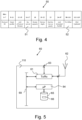
- Figure 4 schematically illustrates an example 50 of a detailed format of MAC sub-layer beacon payload.
- the reserved bits 51 and Tx offset 52 may be used to realise the transmission of the coordinator or node temporal indication, that is, the commissioning start time recorded by the coordinator device or the node device.
- the reserved bits 51 may be used to indicate whether the selective commissioning is applied or enabled. For example, when "01" is set for the bits 16 and 17, it represents that the selective commissioning is enabled.
- Tx offset 52 may be used to store the commissioning start time. This section contains 24 bits and may store the absolute or the relative time, which respectively records the time when the commissioning starts or a passed time from the commissioning starts.
- the coordinator device may further generate and include a flag in the transmitted network-available message.
- the flag may be a random number generated by the coordinator device within a very short time period, such as a small time window, from when the commissioning procedure is started.
- the coordinator device will receive many beacon requests at the beginning of the commissioning procedure, especially for a large scale network.
- the coordinator will generate a limited number of flags, depending on the number of node devices to be commissioned or joined into its network, and include the flags in the network-available messages, that is, the beacon response messages, that the coordinator device transmits.
- Beacon response messages transmitted after the short period of time will return to a regular state and includes no random number.
- the coordinator device will always send network beacons and the node devices just listen.
- the coordinator will control the network beacons containing the random numbers used for commissioning in a similar way, to ensure that only network beacons transmitted within a short period after the commissioning procedure starts includes the random number as the flag.
- the "Tx offset" 52 may also be used to store the flag generated by the coordinator device.
- the node device receiving the network-available message from the coordinator device compares the coordinator temporal indication and the node temporal indication and determines that the two temporal indications match each other.
- the node device calculates a time difference between the commissioning start time recorded by the coordinator device and a commissioning start time as recorded locally by the node device itself. If the time difference is small enough, for example, smaller than a predefined threshold value, such as 0.5 second, it is determined that the commissioning start time in the network-available message is similar to the commissioning start time of the node device. This suggests that the currently available network is the network that the node device should join.
- a predefined threshold value such as 0.5 second
- the node device In the case that the network-available message also comprises the random number as the flag, the node device first determines that the coordinator temporal indication matches the node temporal indication. Knowing that the currently available network is the correct network to join, the node device will store the random number received from the coordinator device. Otherwise it will discard the random number and wait for other messages for joining other networks.
- the node device After confirming that the network created by the coordinator device is the network it should join, the node device, at step 44, transmits a joining request, such as an association request, to the coordinator device.
- a joining request such as an association request
- the node device in transmitting the joining request, also includes its own commissioning start time, and optionally the received flag, in the joining message, such that the coordinator device may also check and confirm that the commissioning start time of the coordinator device and the commissioning start time of the node device match each other.
- the commissioning start time of the node device that is included as the node temporal indication in the joining request is calculated as from time zero until when the joining message is transmitted.
- the node device can transmit the joining request including its commissioning start time right after receiving the network-available message. This still allows the coordinator device to determine that the commissioning start time of the node device is the same or very close to the commissioning start time of the coordinator device in the following step.
- the coordinator device receives the joining request and checks to determine that the commissioning stat time of the node device is similar to the commissioning start time of the coordinator device.
- the coordinator device can perform the checking in the same way as the node device.
- the coordinator device In the case that the received flag is also included in the transmitted joining request, the coordinator device also checks to see that the received flag is one of the flag that it generated and transmitted to the node device. This further confirms that the commissioning start time recorded by the coordinator device and the commissioning start time recorded by the node device are the same or very similar to each other.
- the coordinator device Upon confirming that the commissioning stat time of the node device is similar or the same to the commissioning start time of the coordinator device, at step 46, the coordinator device will allow the node device to join the network, which may be performed according to standard protocol.
- the coordinator device may send an association response to the node device, which contains a short address of the node device. Then the node device will apply a network key and send out a data request. The coordinator device then returns the network key to the node.
- the commission process is complete. After commissioning, the Tx offset could still be used as the original parameter.
- the above describes the method of selectively commissioning node devices by the coordinator device, which only allows node devices that are switched on or powered up at the same time with the coordinator device, or very shortly after the coordinator device, to join the network created by the coordinator device. It thereby ensues that only node devices desirable to join the network will be pulled into the network, while preventing other node devices, such as those node devices which are powered up before the coordinator node device is powered up, from being mistakenly joined into the network.
- Figure 5 illustrates, in a schematic diagram, a coordinator device 60 arranged for performing the method as described above.
- the coordinator device 60 operates a communication interface 61, such as a network adapter or transceiver, Tx/Rx, module arranged for wireless 52 or wired 53 exchange of messages or data packets, such as the network-available message, the joining message as described above, with node device in the network created by the coordinator device 60.
- Network protocols for exchanging data by networked coordinator device and node devices may comprise ZigBee TM , Bluetooth TM , as well as WiFi based protocols for wireless networks, and wired bus networks such as DALI TM (Digital Addressable Lighting Interface), DSI (Digital Serial Interface), DMX (Digital Multiplex), and KNX (or KNX based systems), and other proprietary protocols.
- the coordinator device 60 further comprises at least one microprocessor, ⁇ P, or controller 64, and at least one data repository or storage or memory 65, among others for storing for example network identify of the coordinator device 66, as well as information related to the node devices, such as identifiers, IDs, Media Access Control, MAC, addresses, and subscriber information of node devices.
- the data repository 65 may also store the commissioning start time recorded by the coordinator device 60. Instead of the data repository 65, a separate memory or storage accessible to the at least one processor or controller 64 may be provided.
- the at least one microprocessor or controller 64 communicatively interacts with and controls the communication interface 61 and the at least one data repository or storage 65 via an internal data communication and control bus 69 of the coordinator device 60.
- the at least one microprocessor or controller 64 may operate one or a plurality of selective commissioning algorithms or applications, such as for controlling the node devices, and the protocol stack of the node device 100 comprising the MAC sub-layer functionality to perform the method of selectively commissioning node devices described above.
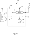
- Figure 6 illustrates, in a schematic diagram, a node device 70 arranged for being commissioned by the coordinator device 60 of Figure 5 in accordance with the method as described above.
- the node device 70 comprises a control part or control device 710 and a load such as a lighting fixture or lighting device 720, comprising a lighting module 721, preferably a Light Emitting Diode, LED, lighting module or a plurality of LED lighting modules, operation of which may be controlled by the control device 710 from or through a remote control device, such as a remote or backend server (not shown), for example.
- a lighting fixture or lighting device 720 comprising a lighting module 721, preferably a Light Emitting Diode, LED, lighting module or a plurality of LED lighting modules, operation of which may be controlled by the control device 710 from or through a remote control device, such as a remote or backend server (not shown), for example.
- the control device 710 operates a communication interface 71, such as a network adapter or transceiver, Tx/Rx, module arranged for short-range wireless 72 or wired 73 exchange of messages or data packets with another node device in the network, i.e. so called inter-node device communication, and with the coordinator device.
- Network protocols for exchanging data by networked devices or nodes may comprise ZigBee TM , Bluetooth TM , as well as WiFi based protocols for wireless networks, and wired bus networks such as DALI TM (Digital Addressable Lighting Interface), DSI (Digital Serial Interface), DMX (Digital Multiplex), and KNX (or KNX based systems), and other proprietary protocols.
- the control device 710 further comprises at least one microprocessor, ⁇ P, or controller 75, and at least one data repository or storage or memory 76, among others for storing address information 77 of the node device itself and other node devices, such as identifiers, IDs, Media Access Control, MAC, addresses, and subscriber information of node devices.
- the data repository 76 may also store the coordinator temporal indication related to the commissioning start time recorded by the coordinator device that the that the node device 70 receives from the coordinator device, and its own temporal indication related to the commissioning start time that it records.
- a separate memory or storage accessible to the at least one processor or controller 75 may be provided.
- the at least one microprocessor or controller 75 communicatively interacts with and controls the communication interface 71, and the at least one data repository or storage 76 via an internal data communication and control bus 79 of the control device 710.
- the at least one microprocessor or controller 75 may operate one or a plurality of algorithms or applications, and the protocol stack of the node device 70 comprising the MAC sub-layer functionality to interact with the coordinator device and perform the method of being selectively commissioned by the coordinator device.
- the lighting fixture or lighting device 720 connects to and is controlled from the data communication and control bus 79 by the at least one microprocessor or controller 710 via a connection link 74.
- any electric load may be connected, via the connection link, 74 to the control bus 79 other than or in addition to a lighting fixture or lighting device 720, such as an access point device or a geographic routing device.
Landscapes
- Engineering & Computer Science (AREA)
- Computer Networks & Wireless Communication (AREA)
- Signal Processing (AREA)
- Health & Medical Sciences (AREA)
- Computing Systems (AREA)
- General Health & Medical Sciences (AREA)
- Medical Informatics (AREA)
- Mobile Radio Communication Systems (AREA)
Claims (15)
- Procédé de mise en service sélective d'un dispositif de noeud (11, 21) par un dispositif coordinateur (10, 20) dans un réseau créé par ledit dispositif coordinateur (10, 20), ledit procédé comprenant les étapes consistant à :- stocker (41), par ledit dispositif coordinateur, une heure de début de mise en service ;- transmettre (42), par ledit dispositif coordinateur (10, 20), un message de réseau disponible indiquant la présence ou la disponibilité du réseau créé par le dispositif coordinateur (10, 20) ;- recevoir (44), par ledit dispositif coordinateur (10, 20), une demande d'intégration transmise par ledit dispositif de noeud (11, 21) lors de la réception dudit message de réseau disponible, comprenant une indication temporelle de noeud liée à ladite heure de début de mise en service dudit dispositif de noeud ;- déterminer (45), par ledit dispositif coordinateur (10, 20), que ladite heure de début de mise en service dudit dispositif coordinateur correspond à ladite indication temporelle de noeud, et- mettre en service (46), par ledit dispositif coordinateur (10, 20), ledit dispositif de noeud en intégrant ledit dispositif de noeud dans ledit réseau.
- Procédé selon la revendication 1, dans lequel ledit message de réseau disponible comprend une indication temporelle de coordinateur liée à ladite heure de début de mise en service dudit dispositif coordinateur (10, 20) et ladite demande d'intégration est transmise par ledit dispositif de noeud (11, 21) en réponse à la détermination du fait que ladite indication temporelle de coordinateur correspond à ladite indication temporelle de noeud.
- Procédé selon la revendication 1 ou 2, dans lequel ladite étape de transmission comprend l'un parmi la diffusion, par ledit dispositif coordinateur (10, 20), d'un message de balise indiquant la disponibilité dudit réseau comme ledit message de réseau disponible, et la transmission, par ledit dispositif coordinateur (10, 20), en réponse à la réception d'un message de demande de balise à partir dudit dispositif noeud (11, 21), d'un message de réponse de balise indiquant la disponibilité dudit réseau comme ledit message de réseau disponible.
- Procédé selon l'une quelconque des revendications précédentes, dans lequel ladite étape de détermination du fait que ladite indication de coordinateur correspond à ladite indication de noeud comprend les étapes consistant à :- calculer, par ledit dispositif coordinateur (10, 20), une différence de temps entre ladite heure de début de mise en service dudit dispositif coordinateur (10, 20) et ladite heure de début de mise en service dudit dispositif de noeud, et- décider, par ledit dispositif coordinateur (10, 20), que ladite différence de temps est inférieure à une valeur seuil prédéfinie.
- Procédé selon la revendication 4, dans lequel ladite indication temporelle de coordinateur liée à ladite heure de début de mise en service dudit dispositif coordinateur (10, 20) comprend un premier temps écoulé depuis la mise sous tension dudit dispositif coordinateur (10, 20) jusqu'à ce que ledit message de réseau disponible soit transmis par ledit dispositif coordinateur (10, 20), ladite indication temporelle de noeud liée à ladite heure de début de mise en service dudit dispositif de noeud comprend un second temps écoulé depuis la mise sous tension dudit dispositif de noeud (11, 21) jusqu'à ce que ladite demande d'intégration soit transmise par ledit dispositif de noeud (11, 21), ladite étape consistant à calculer comprend le calcul d'une différence de temps entre ledit premier temps écoulé et ledit second temps écoulé.
- Procédé selon la revendication 4, dans lequel ledit dispositif coordinateur (10, 20) et ledit dispositif de noeud (11, 21) sont synchronisés et mis sous tension sensiblement en même temps, ladite indication temporelle de coordinateur liée à ladite heure de début de mise en service dudit dispositif coordinateur (10, 20) comprend un premier moment où ledit dispositif coordinateur (10, 20) est mis sous tension, ladite indication temporelle de noeud liée à ladite heure de début de mise en service dudit dispositif de noeud (11, 21) comprend un second moment où ledit dispositif de noeud (11, 21) est mis sous tension, ladite étape consistant à calculer comprend le calcul d'une différence de temps entre ledit premier moment et ledit second moment.
- Procédé selon l'une quelconque des revendications précédentes, dans lequel ledit message de réseau disponible transmis comprend en outre l'un d'une pluralité de drapeaux générés par ledit dispositif coordinateur (10, 20) dans une fenêtre temporelle subséquente à la création dudit réseau, ladite demande d'intégration comprend en outre ledit drapeau.
- Procédé selon la revendication 7, ladite étape consistant à déterminer que ladite indication de coordinateur correspond à ladite indication de noeud comprend en outre la détermination du fait que ledit indicateur compris dans ladite demande d'intégration correspond à l'un de ladite pluralité de drapeaux.
- Procédé selon l'une quelconque des revendications précédentes, dans lequel ledit message de réseau disponible transmis est transmis à des dispositifs de noeud (11, 21) dans un nombre limité de bonds à l'écart dudit dispositif coordinateur (10, 20).
- Procédé selon l'une quelconque des revendications précédentes, chacun dudit dispositif coordinateur (10, 20) et dudit dispositif de noeud (11, 21) fonctionnant conformément à une sous-couche de protocole de traitement de données de contrôle d'accès au support, MAC, dans lequel ladite indication temporelle de coordinateur et ladite indication temporelle de noeud sont respectivement comprises dans un champ de décalage de transmission MAC dudit message de réseau disponible et de ladite demande d'intégration.
- Procédé selon la revendication 10, dans lequel ladite étape consistant à déterminer est effectuée par ladite sous-couche de protocole de traitement de données MAC.
- Dispositif coordinateur (10, 20) conçu pour mettre en service sélectivement un dispositif de noeud dans un réseau créé par ledit dispositif coordinateur (10, 20) selon le procédé de l'une quelconque des revendications précédentes.
- Dispositif de noeud (11, 21) conçu pour être mis en service sélectivement selon le procédé de l'une quelconque des revendications 1 à 12.
- Dispositif de noeud (11, 21) selon la revendication 13, comprenant un appareil d'éclairage.
- Produit-programme informatique, comprenant un support de stockage lisible par ordinateur stockant des instructions qui, lorsqu'elles sont exécutées sur au moins un processeur, amènent ledit au moins un processeur à exécuter le procédé selon l'une quelconque des revendications 1 à 12.
Applications Claiming Priority (3)
| Application Number | Priority Date | Filing Date | Title |
|---|---|---|---|
| CN2020074754 | 2020-02-11 | ||
| EP20169167 | 2020-04-10 | ||
| PCT/EP2021/052947 WO2021160555A1 (fr) | 2020-02-11 | 2021-02-08 | Procédé et dispositif coordinateur pour la mise en service sélective d'un dispositif de nœud dans un réseau |
Publications (3)
| Publication Number | Publication Date |
|---|---|
| EP4104420A1 EP4104420A1 (fr) | 2022-12-21 |
| EP4104420C0 EP4104420C0 (fr) | 2024-10-16 |
| EP4104420B1 true EP4104420B1 (fr) | 2024-10-16 |
Family
ID=74553845
Family Applications (1)
| Application Number | Title | Priority Date | Filing Date |
|---|---|---|---|
| EP21703463.6A Active EP4104420B1 (fr) | 2020-02-11 | 2021-02-08 | Procédé et dispositif coordinateur pour la mise en sélective d'un dispositif de noeud dans un réseau |
Country Status (6)
| Country | Link |
|---|---|
| US (1) | US12028175B2 (fr) |
| EP (1) | EP4104420B1 (fr) |
| JP (1) | JP7629020B2 (fr) |
| CN (1) | CN115104298B (fr) |
| ES (1) | ES2994948T3 (fr) |
| WO (1) | WO2021160555A1 (fr) |
Families Citing this family (5)
| Publication number | Priority date | Publication date | Assignee | Title |
|---|---|---|---|---|
| US11592723B2 (en) | 2009-12-22 | 2023-02-28 | View, Inc. | Automated commissioning of controllers in a window network |
| US12498609B2 (en) | 2011-03-16 | 2025-12-16 | View Operating Corporation | Commissioning window networks |
| EP4089262A1 (fr) | 2016-03-09 | 2022-11-16 | View, Inc. | Procédé de mise en service de fenêtres électrochromiques |
| TW202206925A (zh) | 2020-03-26 | 2022-02-16 | 美商視野公司 | 多用戶端網路中之存取及傳訊 |
| CN121079959A (zh) * | 2023-03-16 | 2025-12-05 | 唯景操作公司 | 调试光可切换窗 |
Citations (1)
| Publication number | Priority date | Publication date | Assignee | Title |
|---|---|---|---|---|
| US20160248629A1 (en) * | 2013-10-04 | 2016-08-25 | Philips Lighting Holding B.V. | Method and apparatus for inter-profile commissioning in a network |
Family Cites Families (14)
| Publication number | Priority date | Publication date | Assignee | Title |
|---|---|---|---|---|
| WO2000016568A1 (fr) | 1998-09-15 | 2000-03-23 | In Touch Technologies Limited | Services de communication |
| JP4687975B2 (ja) | 2005-11-21 | 2011-05-25 | ブラザー工業株式会社 | 無線タグ情報読み取り装置 |
| TWI376122B (en) * | 2008-12-15 | 2012-11-01 | Ind Tech Res Inst | Method and system for a new node to join a wireless ad-hoc network |
| US8655995B2 (en) * | 2009-01-13 | 2014-02-18 | Whirlpool Corporation | Home network commissioning |
| KR101828412B1 (ko) | 2011-12-13 | 2018-02-13 | 삼성전자주식회사 | 통신 방법, 통신 장치 및 통신 시스템 |
| EP3011768B1 (fr) | 2013-06-17 | 2020-09-23 | Signify Holding B.V. | Procédé permettant de configurer un noeud et noeud configuré en conséquence |
| US11388082B2 (en) * | 2013-11-27 | 2022-07-12 | Oracle International Corporation | Methods, systems, and computer readable media for diameter routing using software defined network (SDN) functionality |
| EP3075206B1 (fr) | 2013-11-29 | 2017-11-01 | Philips Lighting Holding B.V. | Mise en service de réseau de liaison d'éclairage zigbee |
| CN103763714B (zh) * | 2013-12-31 | 2017-04-19 | 大唐电信(天津)技术服务有限公司 | 一种基于zigbee的无线传感器网络的优化方法 |
| US20150350906A1 (en) | 2014-05-30 | 2015-12-03 | Qualcomm Incorporated | Systems and methods for selective association |
| EP3141010B1 (fr) | 2014-06-24 | 2019-09-11 | Google LLC | Inbetriebnahme eines mesh-netzwerks |
| CA3003146C (fr) | 2015-10-30 | 2020-08-25 | Lutron Electronics Co., Inc. | Mise en service de systemes de commande de charge |
| US9999557B2 (en) | 2016-07-14 | 2018-06-19 | Challenging Solutions, Inc. | Robotic mobility device |
| CN112292874B (zh) | 2018-06-26 | 2024-04-16 | 昕诺飞控股有限公司 | 在ZigBee网络中优化入网初始化 |
-
2021
- 2021-02-08 WO PCT/EP2021/052947 patent/WO2021160555A1/fr not_active Ceased
- 2021-02-08 ES ES21703463T patent/ES2994948T3/es active Active
- 2021-02-08 US US17/796,005 patent/US12028175B2/en active Active
- 2021-02-08 CN CN202180013929.6A patent/CN115104298B/zh active Active
- 2021-02-08 JP JP2022548712A patent/JP7629020B2/ja active Active
- 2021-02-08 EP EP21703463.6A patent/EP4104420B1/fr active Active
Patent Citations (1)
| Publication number | Priority date | Publication date | Assignee | Title |
|---|---|---|---|---|
| US20160248629A1 (en) * | 2013-10-04 | 2016-08-25 | Philips Lighting Holding B.V. | Method and apparatus for inter-profile commissioning in a network |
Also Published As
| Publication number | Publication date |
|---|---|
| US12028175B2 (en) | 2024-07-02 |
| JP7629020B2 (ja) | 2025-02-12 |
| JP2023513323A (ja) | 2023-03-30 |
| CN115104298A (zh) | 2022-09-23 |
| WO2021160555A1 (fr) | 2021-08-19 |
| CN115104298B (zh) | 2025-09-12 |
| EP4104420A1 (fr) | 2022-12-21 |
| EP4104420C0 (fr) | 2024-10-16 |
| US20230050614A1 (en) | 2023-02-16 |
| ES2994948T3 (en) | 2025-02-04 |
Similar Documents
| Publication | Publication Date | Title |
|---|---|---|
| EP4104420B1 (fr) | Procédé et dispositif coordinateur pour la mise en sélective d'un dispositif de noeud dans un réseau | |
| US7821964B2 (en) | Methods and systems for network coordination | |
| CN102171948B (zh) | 在通信系统中传送要由空闲用户单元监视的信道的方法 | |
| KR100633353B1 (ko) | 그물형 네트워크의 중앙 제어 장치 및 방법 | |
| CN100512174C (zh) | 一种家庭网络无线组网和通讯的方法 | |
| KR100906083B1 (ko) | 브리지 터미널들을 통해 상호접속될 수 있는 서브네트워크들을 갖는 네트워크 | |
| CN116210341B (zh) | 用于管理侧行传输的方法和设备 | |
| US20150019718A1 (en) | Method for service discovery in wireless personal area network | |
| JP4192328B2 (ja) | 無線伝送方法及び無線伝送装置 | |
| CN101138173B (zh) | 无线通信装置及无线通信方法 | |
| KR100748094B1 (ko) | 802.15.4 wpan포설 방법 및 이를 위한 장치 | |
| WO2021136719A1 (fr) | Procédé de fourniture de dispositifs de noeud d'un réseau à partir d'un serveur dorsal, dispositif de noeud et serveur dorsal | |
| KR20090029607A (ko) | 개인 영역 네트워크 시스템 및 그 비콘 스케줄링 방법 | |
| CN101601324B (zh) | 无线非蜂窝网络 | |
| US8315205B2 (en) | Wireless star networks with dual adaptive central nodes | |
| CN114339706A (zh) | 在蓝牙Mesh网络中对多个待配网设备进行启动配置的方法 | |
| KR100587013B1 (ko) | ZigBee 개인 영역 네트워크(PAN) 간 통신 방법 | |
| JP2005277633A (ja) | 媒体アクセス制御方法及び電力線通信方法 | |
| US20240179824A1 (en) | A method of joining a node device into a wireless network and a node device | |
| EP4158879B1 (fr) | Communication fiable et sensible à la sécurité dans un réseau sans fil hybride | |
| WO2022238153A1 (fr) | Un procédé et un dispositif de nœud pour communiquer des informations de réseau à un dispositif de nœuds non mis en service devant être ajouté à un réseau et un procédé pour joindre un dispositif de nœuds non mis en service dans un réseau | |
| JP2004128893A (ja) | 無線通信装置、無線通信方法および無線通信システム |
Legal Events
| Date | Code | Title | Description |
|---|---|---|---|
| STAA | Information on the status of an ep patent application or granted ep patent |
Free format text: STATUS: UNKNOWN |
|
| STAA | Information on the status of an ep patent application or granted ep patent |
Free format text: STATUS: THE INTERNATIONAL PUBLICATION HAS BEEN MADE |
|
| PUAI | Public reference made under article 153(3) epc to a published international application that has entered the european phase |
Free format text: ORIGINAL CODE: 0009012 |
|
| STAA | Information on the status of an ep patent application or granted ep patent |
Free format text: STATUS: REQUEST FOR EXAMINATION WAS MADE |
|
| 17P | Request for examination filed |
Effective date: 20220912 |
|
| AK | Designated contracting states |
Kind code of ref document: A1 Designated state(s): AL AT BE BG CH CY CZ DE DK EE ES FI FR GB GR HR HU IE IS IT LI LT LU LV MC MK MT NL NO PL PT RO RS SE SI SK SM TR |
|
| DAV | Request for validation of the european patent (deleted) | ||
| DAX | Request for extension of the european patent (deleted) | ||
| STAA | Information on the status of an ep patent application or granted ep patent |
Free format text: STATUS: EXAMINATION IS IN PROGRESS |
|
| 17Q | First examination report despatched |
Effective date: 20240318 |
|
| REG | Reference to a national code |
Ref country code: DE Ref legal event code: R079 Free format text: PREVIOUS MAIN CLASS: H04L0029080000 Ipc: H04L0067125000 Ref country code: DE Ref legal event code: R079 Ref document number: 602021020323 Country of ref document: DE Free format text: PREVIOUS MAIN CLASS: H04L0029080000 Ipc: H04L0067125000 |
|
| GRAP | Despatch of communication of intention to grant a patent |
Free format text: ORIGINAL CODE: EPIDOSNIGR1 |
|
| STAA | Information on the status of an ep patent application or granted ep patent |
Free format text: STATUS: GRANT OF PATENT IS INTENDED |
|
| RIC1 | Information provided on ipc code assigned before grant |
Ipc: H05B 47/19 20200101ALI20240418BHEP Ipc: H04W 84/20 20090101ALI20240418BHEP Ipc: H04W 84/18 20090101ALI20240418BHEP Ipc: H04L 12/12 20060101ALI20240418BHEP Ipc: H04L 67/125 20220101AFI20240418BHEP |
|
| INTG | Intention to grant announced |
Effective date: 20240514 |
|
| GRAS | Grant fee paid |
Free format text: ORIGINAL CODE: EPIDOSNIGR3 |
|
| GRAA | (expected) grant |
Free format text: ORIGINAL CODE: 0009210 |
|
| STAA | Information on the status of an ep patent application or granted ep patent |
Free format text: STATUS: THE PATENT HAS BEEN GRANTED |
|
| AK | Designated contracting states |
Kind code of ref document: B1 Designated state(s): AL AT BE BG CH CY CZ DE DK EE ES FI FR GB GR HR HU IE IS IT LI LT LU LV MC MK MT NL NO PL PT RO RS SE SI SK SM TR |
|
| REG | Reference to a national code |
Ref country code: GB Ref legal event code: FG4D |
|
| REG | Reference to a national code |
Ref country code: CH Ref legal event code: EP Ref country code: DE Ref legal event code: R096 Ref document number: 602021020323 Country of ref document: DE |
|
| REG | Reference to a national code |
Ref country code: IE Ref legal event code: FG4D |
|
| U01 | Request for unitary effect filed |
Effective date: 20241104 |
|
| U07 | Unitary effect registered |
Designated state(s): AT BE BG DE DK EE FI FR IT LT LU LV MT NL PT RO SE SI Effective date: 20241113 |
|
| REG | Reference to a national code |
Ref country code: ES Ref legal event code: FG2A Ref document number: 2994948 Country of ref document: ES Kind code of ref document: T3 Effective date: 20250204 |
|
| U20 | Renewal fee for the european patent with unitary effect paid |
Year of fee payment: 5 Effective date: 20250224 |
|
| PG25 | Lapsed in a contracting state [announced via postgrant information from national office to epo] |
Ref country code: IS Free format text: LAPSE BECAUSE OF FAILURE TO SUBMIT A TRANSLATION OF THE DESCRIPTION OR TO PAY THE FEE WITHIN THE PRESCRIBED TIME-LIMIT Effective date: 20250216 Ref country code: HR Free format text: LAPSE BECAUSE OF FAILURE TO SUBMIT A TRANSLATION OF THE DESCRIPTION OR TO PAY THE FEE WITHIN THE PRESCRIBED TIME-LIMIT Effective date: 20241016 |
|
| PG25 | Lapsed in a contracting state [announced via postgrant information from national office to epo] |
Ref country code: NO Free format text: LAPSE BECAUSE OF FAILURE TO SUBMIT A TRANSLATION OF THE DESCRIPTION OR TO PAY THE FEE WITHIN THE PRESCRIBED TIME-LIMIT Effective date: 20250116 |
|
| PG25 | Lapsed in a contracting state [announced via postgrant information from national office to epo] |
Ref country code: GR Free format text: LAPSE BECAUSE OF FAILURE TO SUBMIT A TRANSLATION OF THE DESCRIPTION OR TO PAY THE FEE WITHIN THE PRESCRIBED TIME-LIMIT Effective date: 20250117 |
|
| PG25 | Lapsed in a contracting state [announced via postgrant information from national office to epo] |
Ref country code: PL Free format text: LAPSE BECAUSE OF FAILURE TO SUBMIT A TRANSLATION OF THE DESCRIPTION OR TO PAY THE FEE WITHIN THE PRESCRIBED TIME-LIMIT Effective date: 20241016 |
|
| PG25 | Lapsed in a contracting state [announced via postgrant information from national office to epo] |
Ref country code: RS Free format text: LAPSE BECAUSE OF FAILURE TO SUBMIT A TRANSLATION OF THE DESCRIPTION OR TO PAY THE FEE WITHIN THE PRESCRIBED TIME-LIMIT Effective date: 20250116 |
|
| PG25 | Lapsed in a contracting state [announced via postgrant information from national office to epo] |
Ref country code: SM Free format text: LAPSE BECAUSE OF FAILURE TO SUBMIT A TRANSLATION OF THE DESCRIPTION OR TO PAY THE FEE WITHIN THE PRESCRIBED TIME-LIMIT Effective date: 20241016 |
|
| PG25 | Lapsed in a contracting state [announced via postgrant information from national office to epo] |
Ref country code: SK Free format text: LAPSE BECAUSE OF FAILURE TO SUBMIT A TRANSLATION OF THE DESCRIPTION OR TO PAY THE FEE WITHIN THE PRESCRIBED TIME-LIMIT Effective date: 20241016 |
|
| PG25 | Lapsed in a contracting state [announced via postgrant information from national office to epo] |
Ref country code: CZ Free format text: LAPSE BECAUSE OF FAILURE TO SUBMIT A TRANSLATION OF THE DESCRIPTION OR TO PAY THE FEE WITHIN THE PRESCRIBED TIME-LIMIT Effective date: 20241016 |
|
| PLBE | No opposition filed within time limit |
Free format text: ORIGINAL CODE: 0009261 |
|
| STAA | Information on the status of an ep patent application or granted ep patent |
Free format text: STATUS: NO OPPOSITION FILED WITHIN TIME LIMIT |
|
| PG25 | Lapsed in a contracting state [announced via postgrant information from national office to epo] |
Ref country code: MC Free format text: LAPSE BECAUSE OF FAILURE TO SUBMIT A TRANSLATION OF THE DESCRIPTION OR TO PAY THE FEE WITHIN THE PRESCRIBED TIME-LIMIT Effective date: 20241016 |
|
| 26N | No opposition filed |
Effective date: 20250717 |
|
| REG | Reference to a national code |
Ref country code: CH Ref legal event code: PL |
|
| PG25 | Lapsed in a contracting state [announced via postgrant information from national office to epo] |
Ref country code: CH Free format text: LAPSE BECAUSE OF NON-PAYMENT OF DUE FEES Effective date: 20250228 |
|
| PG25 | Lapsed in a contracting state [announced via postgrant information from national office to epo] |
Ref country code: IE Free format text: LAPSE BECAUSE OF NON-PAYMENT OF DUE FEES Effective date: 20250208 |
|
| U20 | Renewal fee for the european patent with unitary effect paid |
Year of fee payment: 6 Effective date: 20260224 |
|
| PGFP | Annual fee paid to national office [announced via postgrant information from national office to epo] |
Ref country code: GB Payment date: 20260223 Year of fee payment: 6 |
|
| PGFP | Annual fee paid to national office [announced via postgrant information from national office to epo] |
Ref country code: ES Payment date: 20260317 Year of fee payment: 6 |