EP4104929A1 - Mikroplattenanordnung für mehrere proben - Google Patents
Mikroplattenanordnung für mehrere proben Download PDFInfo
- Publication number
- EP4104929A1 EP4104929A1 EP21179676.8A EP21179676A EP4104929A1 EP 4104929 A1 EP4104929 A1 EP 4104929A1 EP 21179676 A EP21179676 A EP 21179676A EP 4104929 A1 EP4104929 A1 EP 4104929A1
- Authority
- EP
- European Patent Office
- Prior art keywords
- microplate
- duct
- assembly according
- pressure
- baseplate
- Prior art date
- Legal status (The legal status is an assumption and is not a legal conclusion. Google has not performed a legal analysis and makes no representation as to the accuracy of the status listed.)
- Pending
Links
Images




Classifications
-
- B—PERFORMING OPERATIONS; TRANSPORTING
- B01—PHYSICAL OR CHEMICAL PROCESSES OR APPARATUS IN GENERAL
- B01L—CHEMICAL OR PHYSICAL LABORATORY APPARATUS FOR GENERAL USE
- B01L3/00—Containers or dishes for laboratory use, e.g. laboratory glassware; Droppers
- B01L3/50—Containers for the purpose of retaining a material to be analysed, e.g. test tubes
- B01L3/508—Rigid containers without fluid transport within
- B01L3/5085—Rigid containers without fluid transport within for multiple samples, e.g. microtitration plates
- B01L3/50853—Rigid containers without fluid transport within for multiple samples, e.g. microtitration plates with covers or lids
-
- B—PERFORMING OPERATIONS; TRANSPORTING
- B01—PHYSICAL OR CHEMICAL PROCESSES OR APPARATUS IN GENERAL
- B01L—CHEMICAL OR PHYSICAL LABORATORY APPARATUS FOR GENERAL USE
- B01L2200/00—Solutions for specific problems relating to chemical or physical laboratory apparatus
- B01L2200/06—Fluid handling related problems
- B01L2200/0684—Venting, avoiding backpressure, avoid gas bubbles
-
- B—PERFORMING OPERATIONS; TRANSPORTING
- B01—PHYSICAL OR CHEMICAL PROCESSES OR APPARATUS IN GENERAL
- B01L—CHEMICAL OR PHYSICAL LABORATORY APPARATUS FOR GENERAL USE
- B01L2200/00—Solutions for specific problems relating to chemical or physical laboratory apparatus
- B01L2200/06—Fluid handling related problems
- B01L2200/0689—Sealing
-
- B—PERFORMING OPERATIONS; TRANSPORTING
- B01—PHYSICAL OR CHEMICAL PROCESSES OR APPARATUS IN GENERAL
- B01L—CHEMICAL OR PHYSICAL LABORATORY APPARATUS FOR GENERAL USE
- B01L2300/00—Additional constructional details
- B01L2300/04—Closures and closing means
- B01L2300/041—Connecting closures to device or container
-
- B—PERFORMING OPERATIONS; TRANSPORTING
- B01—PHYSICAL OR CHEMICAL PROCESSES OR APPARATUS IN GENERAL
- B01L—CHEMICAL OR PHYSICAL LABORATORY APPARATUS FOR GENERAL USE
- B01L2300/00—Additional constructional details
- B01L2300/08—Geometry, shape and general structure
- B01L2300/0809—Geometry, shape and general structure rectangular shaped
- B01L2300/0829—Multi-well plates; Microtitration plates
-
- B—PERFORMING OPERATIONS; TRANSPORTING
- B01—PHYSICAL OR CHEMICAL PROCESSES OR APPARATUS IN GENERAL
- B01L—CHEMICAL OR PHYSICAL LABORATORY APPARATUS FOR GENERAL USE
- B01L2400/00—Moving or stopping fluids
- B01L2400/04—Moving fluids with specific forces or mechanical means
- B01L2400/0475—Moving fluids with specific forces or mechanical means specific mechanical means and fluid pressure
- B01L2400/0487—Moving fluids with specific forces or mechanical means specific mechanical means and fluid pressure fluid pressure, pneumatics
- B01L2400/049—Moving fluids with specific forces or mechanical means specific mechanical means and fluid pressure fluid pressure, pneumatics vacuum
-
- B—PERFORMING OPERATIONS; TRANSPORTING
- B01—PHYSICAL OR CHEMICAL PROCESSES OR APPARATUS IN GENERAL
- B01L—CHEMICAL OR PHYSICAL LABORATORY APPARATUS FOR GENERAL USE
- B01L2400/00—Moving or stopping fluids
- B01L2400/06—Valves, specific forms thereof
- B01L2400/0605—Valves, specific forms thereof check valves
Definitions
- the invention relates to a microplate assembly for a plurality of samples and a method for mixing samples by means of the microplate assembly.
- Microplates are available in numerous formats ranging from a single cavity or well, to 1000s or tens or hundreds of 1000s of cavities. Such microplates are typically made from plastics like polystyrene and feature cavity geometries and volumes that match the requirements of a particular application. A variety of different types of microplates exist for these specialised applications. Often these microplates comply with an industry standard published by ANSI-SLAS, that aims at ensuring interoperability with laboratory equipment such as robotics, liquid handling systems, centrifuges, thermo cyclers, and readout devices like plate readers, microscopes, or next-generation sequencing instruments.
- Microplates are used in life sciences, diagnostics, bioprocessing, and therapeutic applications for the storage of compounds, buffers, and reaction mixtures, performing reactions such as polymerase chain reaction or enzymatic assays such as ELISA-assays, cultivating cells and other biological samples, performing assays with biological samples such as cell-based assays for phenotypic screening.
- Phenotypic screening is used in academic, translational research and pharmaceutic development to find for example drug candidates that modulate the function of a certain disease-relevant drug target.
- Phenotypic screening of monolayer cell culture generally pre-cultivated in flasks before they are dispensed into a microplate in which they are further cultivated, subject to treatment, stained and then read-out.
- cells are generally pre-cultivated in flasks before they are dispensed into a microplate in which they are further cultivated into a 3D structure for example a spheroid, a tumoroid, or an organoid before they are subject to treatment, staining and read-out.
- the microplate used for the cultivation step is typically a round-bottom ultra-low attachment plate, which inhibits the attachment of cells to the bottom of the cavity and facilitates the aggregation of cells and formation of spheroids, tumoroids, or organoids.
- Such a workflow may be performed manually, which may be suitable to support the cultivation of several 100s of organoids per working day, or automated as described in Renner et al. 2020 (https://elifesciences.org/articles/52904), which allows the generation of around 20,000 organoids per day.
- US 2021/0016436 A1 discloses a gripping and mobilizing system, which is pneumatically driven.
- a microplate assembly for a plurality of samples comprises a microplate including a plurality of sample cavities and at least one duct, with each sample cavity having a cavity opening and the duct having a first duct opening and a second duct opening connectable to a pressure source.
- the microplate assembly further comprises a detachable lid configured to cover at least the sample cavities and including at least one insertion element, wherein the insertion element is arranged and configured to be receivable by the first duct opening, and wherein the duct is configured to conduct pressure in order to move the insertion element and the lid.
- the duct carries a pressurised working medium, such as air, and the lid is moved upon a pressure change in the duct by the pressure source.
- the sample may in particular be a biological sample, such as a cell suspension.
- the insertion element is configured to seal the first duct opening when it is received by the first duct opening.
- the microplate assembly enables the reproducible closing of the microplate, in particular the cavities, with no manual intervention. This makes the microplate assembly particularly suitable for use in an automated laboratory setting. Further, this enables the microplate being reversibly closed in a leak-tight fashion, for example, to allow stabilisation of conditions inside the sample cavity against the environment. Moreover, this enables the spill-proof and safe movement of the microplate in any direction, and allows moving the samples inside the sample cavities by rotating the microplate assembly. The moving of the samples may cause mixing.
- the lid is configured to be pressed against the microplate when the duct is under negative pressure.
- the negative pressure may be a partial vacuum. This enables sealing the cavities of the microplate leak-tight.
- the lid comprises at least one transparent window for microscopic examination.
- the at least one transparent window is arranged such that it aligns with one of the sample cavities. This enables observing the content of the sample cavity with a microscope.
- the microplate comprises at least one check valve, a manifold, and a release valve, wherein the check valve is configured to conduct the pressure from the pressure source to the manifold and the release valve configured to release pressure from the manifold.
- the check valve keeps the negative pressure in the manifold even if the assembly is disconnected from the pressure source.
- the release valve may then be used to release the negative pressure at a later point in order to release the lid of the microplate. This enables particularly flexible operation of the microplate assembly independent of a constant supply of pressure to the baseplate.
- the microplate assembly further comprises a baseplate including a manifold to connect the at least one second duct opening to the pressure source.
- the manifold conducts the pressurised working medium. This enables particularly easy connection of the pressure source to the microplate, in particular to the duct.
- the baseplate comprises at least one check valve configured to conduct the pressure from the pressure source to the manifold and a release valve configured to release pressure from the manifold.
- the check valve keeps the negative pressure in the manifold even if the assembly is disconnected from the pressure source.
- the release valve may then be used to release the negative pressure at a later point in order to release the lid of the microplate. This enables particularly flexible operation of the microplate assembly independent of a constant supply of pressure to the baseplate.
- the baseplate comprises the pressure source. This enables flexible operation of the microplate assembly.
- the pressure source in the baseplate comprises a housing and a leak-tight membrane moveable within the housing.
- the movement of the membrane causes a change of the manifold volume and thus a pressure change in the manifold. This enables particularly flexible operation of the microplate assembly independent of external sources of pressure.
- the membrane is mechanically, pneumatically or magnetically moveable within the housing to change the pressure in the duct. This enables flexible generation of the pressure in the baseplate.
- the microplate assembly further comprises a magnetic element configured to magnetically move the membrane within the housing.
- the magnetic element may be an electromagnet, for example. This enables flexible switching of the polarity of the magnetic element and therefore changing the pressure in the manifold.
- the membrane is lockable in a stretched state by at least one locking element.
- the membrane In the stretched state, the membrane is positioned such that the manifold volume is increased and a negative pressure is generated in the manifold. This enables flexible operation of the microplate assembly without a constant supply to an external pressure source.
- the insertion element is elastic.
- the insertion element may be made from rubber. This enables a particularly good fit of the insertion element in the first duct opening in order to seal the first duct opening when the lid is placed on the microplate.
- the lid comprises the same number of insertion elements as there are ducts in the microplate. This enables the lid to fit the microplate and the generation of negative pressure in the manifold.
- the cavity opening and the first duct opening are on a first side of the microplate and the second duct opening are on a second side of the microplate. This enables particularly easy access to the second duct opening.
- the second side of the microplate is opposite of the first side. This enables a particularly easy connection of the duct to the baseplate.
- the microplate and/or the lid comprise cavity seals configured to seal the cavity openings leak-tight when the lid is pressed against the microplate. This enables a particularly leak-tight seal of the cavities.
- each sample cavity has a transparent cavity bottom configured to enable microscopic imaging. This enables particularly easy microscopic imaging of the contents of the cavities.
- each sample cavity has a round cavity bottom configured to enable the cultivation of spheroids, tumoroids, organoids and other 3D cell culture samples in suspension, i.e. without a scaffold. This enables particularly easy cultivation of spheroids, tumoroids, organoids and other 3D cell culture samples.
- a microplate for a microplate assembly comprising a plurality of sample cavities and at least one duct, with each sample cavity having a cavity opening and the duct having a first duct opening and a second duct opening connectable to a pressure source.
- the duct is configured to conduct pressure, and the first duct opening is configured to receive an insertion element.
- a method for mixing samples by means of the microplate assembly comprising the following steps: placing the lid on the microplate in a first orientation; applying negative pressure to seal the sample cavities; turning the microplate into a second orientation; returning the microplate to the first orientation.
- the sealing of the microplate with the lid requires no manual intervention manual, for example by laboratory personnel.
- the microplate assembly enables particularly easy and safe mixing of the contents of the sample cavities of the microplate.
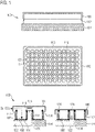
- FIG 1 shows a schematic view, a top view and a sectional view of a microplate assembly 100 comprising a microplate 102, a baseplate 104 and a lid 106.
- the microplate 102 is shown comprising 96 sample cavities 108 that are arranged in an eight by twelve grid. To identify individual cavities 108, a coordinate system can be used whereby rows are identified by letters and columns are identified by numbers.
- the top left cavity 108 of the microplate 102 is identified in Figure 1 as A1. Accordingly, the sample cavity exemplarily identified by the reference sign 108 is at the position C1.
- Each cavity 108 is open to a top side 110 of the microplate 102 and comprises a cavity opening 112.
- This opening 112 opens the cavity 108 on the top side 110 and allows access to the inside of the cavity 108.
- the openings 112 of the microplate 102 in Figure 1 is circular.
- the inner surface of the cavity 108 is circular in planes parallel to the top side 110.
- a cavity bottom 114 of the sample cavity 108 is flat such that the cavity 108 has a rectangular outline in the sectional view.
- the bottom 114 may be transparent, particularly, an optically clear plane-parallel plate.
- the bottom 114 can be manufactured from glass or optical-grade polystyrene, cyclic olefin copolymers or polycarbonate.
- the inside of the cavity 108 can be viewed through the bottom 114, for example with a microscope, in particular with an inverted microscope. This allows observing of, for example, a sample in the cavity 108 with a minimal amount of optical aberrations.
- the distance between the sample and the microscope objective is reduced compared to imaging the sample through the opening 112 of the microplate 102. This is particularly advantageous when using high numerical aperture objectives that require short working distances between front lens of the objective and the imaged sample. As a consequence of this requirement, imaging of samples with a high numerical aperture objective inside the cavity 108 is usually only possible through the bottom 114.
- the cavities 108 may have different geometries to the geometries described above.
- the cavity 108 geometry can be rectangular in planes parallel to the top side 110.
- the bottom 114 may be V-shaped, round or concave.
- the number of cavities 108 of the microplate 102 may be larger or smaller than 96.
- the microplate 102 may comprise 1, 6, 8, 24, 48, 96, 384 or 1536 cavities 108.
- the microplate 102 further comprises ducts 116.
- the microplate 102 comprises 77 ducts 116 that are arranged in a seven by eleven grid, with each duct 116 having a first duct opening 118 on the top side 110 of the microplate 102 and a second duct opening 120 on a bottom side of the microplate 102.
- the microplate 102 may alternatively comprise a different number of ducts 116.
- the ducts 116 are distributed evenly across the top side 110 of the microplate 102.
- the second duct opening 120 of the microplate 102 is connected to the baseplate 104.
- the duct openings 120 of the ducts 116 are connected in a pressure-tight fashion to a manifold 122 of the baseplate 104.
- the manifold 122 may in turn be connected to a pressure source, thus enabling applying pressure to the manifold 122 and the connected ducts 116.
- the baseplate 104 may comprise manifold openings 124 that align with the second duct openings 120.
- the lid 104 comprises insertion elements 126 that are configured to be reversibly receivable by the first duct openings 118.
- the insertion elements 126 may be formed such that they correspond to the shape of the opening 118 in order to fit into the opening 118 and seal the duct 126 in the assembled state of the microplate assembly 100, when the lid 104 is placed on the top side 110 of the microplate 102.
- the insertion elements 126 may be manufactured from an elastic polymer, for example.
- the insertion elements 126 are arranged on the lid 106 such that they align with the ducts 116 when the lid 106 is placed on the top side 110 of the microplate 102.
- the lid 106 comprises the same number of insertion elements 126 as the microplate comprises ducts 116.
- pressure may be applied through the baseplate 104 as discussed above.
- negative pressure such as a partial vacuum from a pressure source such as a vacuum pump
- the insertion elements 126 are pulled into the respective ducts 116.
- the microplate 102 comprises circumferential seals 128 arranged around the openings 112. The seals 128 are compressed when the lid 106 is pulled against the top side 110 of the microplate 102 and seal the cavities 108 leak-tight.
- the lid 106 may comprise a seal on the surface facing the top side 110 of the microplate 102.
- the microplate 102 is firmly attached to the baseplate 104 due to the negative pressure in the manifold 122.
- the microplate 102 is firmly attached to the baseplate 104 by means of fasteners, for example threaded fasteners such as screws.
- the insertion elements 126 When positive pressure is applied from a pressure source to the baseplate 104 and thus the ducts 116, the insertion elements 126 are pushed out of the respective ducts 116. This pushes the lid 106 away from the top side 110 of the microplate 102 and opens the cavities 108. The lid 106 then rests on the top side 110 of the microplate 102 with the insertion elements 126 keeping the lid 106 at a distance from the top side 110 of the microplate 102. This allows mass transfer between the inside of the cavity 108 and the outside, in particular gases such as oxygen and carbon dioxide can be exchanged between the inside and the outside.
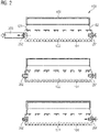
- FIG. 2 shows a schematic view of the microplate assembly 100.
- the baseplate 104 may comprise a check valve 202 and a manual release valve 204 in order to regulate build-up and release of pressure from the assembly, in particular the manifold 122 and the ducts 116.
- the check valve 202 may be connected to the pressure source via a hose 206, for example. When negative pressure is applied the check valve 202 allows the flow of air out of the manifold 122 and the lid 106 is pulled against the microplate 102. When the hose 206 is disconnected the check valve 202 blocks inflow of air into the manifold 122. With the release valve 204 closed, the negative pressure is maintained in the manifold 122 and the ducts 116.
- the lid 106 continues to be pulled against the top side 110 of the microplate 102. This maintains the cavities 108 in the sealed state.
- the release valve 204 can be opened to allow air to flow into the manifold 122 and equalise the pressure inside the manifold 122.
- Figure 3 shows a schematic view of a pressure source station 300 configured to supply pressure to the microplate assembly 100.
- the build-up and release of pressure from the manifold 122 can be controlled by the station 300. Initially, negative pressure may be applied through the valve 202. To release the lid 106, the station 300 may actuate the valve 204. Thus, no manual intervention is necessary to seal and open the microplate 102. This allows automation of the sealing and opening of the microplate 102 and the integration of the microplate assembly 100 in automated laboratory environments.
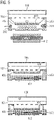
- Figure 4 shows a schematic view of a mechanical baseplate 400 and an electromagnetic baseplate 402.
- the baseplates 400, 402 are configured to act as a pressure source.
- the baseplates 400, 402 each comprise a leak-tight membrane 404, 406 movable within the baseplate 400, 402.
- the leak-tight membranes 404, 406 are moved within the baseplates 400, 402 such that the volume of the leak-tight manifold 122 increases, negative pressure can be generated within the manifold 122 and thus the ducts 116 of the microplate attached to the baseplate 400, 402.
- the membrane 404 of the baseplate 400 is moved mechanically within the baseplate 400, for example, by a moving mechanism that is configured to move the leak-tight membrane 404 in a direction, in which the negative pressure is generated within the manifold 122.
- the membrane 406 of the baseplate 402 is moved electromagnetically within the baseplate 402.
- the membrane 406 comprises a magnetic layer 410, which is configured to be attracted and repelled by an electromagnet 412.
- the electromagnet 412 is set to attract the magnetic layer 410
- the membrane 406 of the baseplate 402 is moved electromagnetically within the baseplate 402 in a direction, in which the negative pressure is generated within the manifold 122.
- the electromagnet is set to repel the magnetic layer 410
- the membrane 406 is moved in a direction, in which the negative pressure is relieved within the manifold 122.
- the magnetic layer 410 may be a layer of ferromagnetic material on the membrane 406 or permanent magnets, for example.
- the membranes 404, 406 may be locked in place by a set of retention elements 408.
- FIG. 5 shows a schematic view of an electromagnetic baseplate 500 and an integrated electromagnetic baseplate 502.
- the electromagnetic baseplate 500 comprises the check valve 202 and the manual release valve 204. These may be used to actuate the membrane 406 of the baseplate 500 by applying negative pressure through the check valve 202 in order to seal and open the microplate 102, as described above. This may be in addition to the magnetic actuation of the membrane 406 by means of the electromagnet 412.
- the integrated electromagnetic baseplate 502 integrates the electromagnet 412 into the baseplate 502 in order to actuate the membrane 406, as described above.
- FIG. 6 shows a schematic of an attachable baseplate 600.
- the baseplate 600 comprises attachment openings 604 that are arranged on a side of the baseplate 600 opposite of the side, on which the manifold openings 124 are arranged.
- the attachment openings 604 are connected to the manifold 122.
- the baseplate 600 When the baseplate 600 is placed on a surface 602 and negative pressure is applied to the manifold 122 of the baseplate 602, as described above, the baseplate 600 may be attached to the surface 602 by means of the negative pressure through the attachment opening 604.
- the side of the baseplate 600 with the attachment openings 604 facing the surface 602 may comprise a seal in order to contain the negative pressure.
- the attachment openings 604 attach the baseplate 600 to the surface 602 by the principle of a suction cup.
- Figure 7 shows a schematic view of a baseplate 700.
- the baseplate 700 comprises an opening 702, in which a guiding rod 704 may be inserted.
- the opening 702 and the guiding rod 704 have complementary shapes and form fit, such that the guiding rod 704 firmly sits in the opening 702 and movement of the guiding rod 704 is transferred to the baseplate 700.
- the baseplate 700 comprises rails 706.
- the baseplate 700 may be attached to a surface comprising rail elements complementary to the rails 706.
- the baseplate 700 may comprise either the opening 702 or the rails 706.
- the baseplate 700 may comprise the membrane 404 or the membrane 406 to generate the negative pressure in the manifold 122 as described above.
- Figures 8 to 10 show a schematic view of a moving device 800 for the baseplate 700.
- the moving device 800 comprises a raising rod 802 and a raising element 804 attached to the rod 802.
- the raising element 804 is configured to move along the length of the raising rod 802.
- the baseplate 700 may be attached to the raising element 804 by means of the guiding rod 704.
- the baseplate 700 together with the microplate 102 sealed by the lid 106 form a microplate assembly 806.
- the microplate assembly 806 may be moved by the moving device 800.
- the microplate assembly 806 may be turned upside down by the moving device 800 when the microplate assembly 806 is in the sealed state ( Figure 10 ). This enables mixing of the contents of the sample cavities 108 of the microplate 102, for example.
- the microplate assembly 806 is then returned to the original orientation ( Figure 8 ).
- the moving device enables automating repeated moving and mixing steps of microplates 102 without manual intervention, for example by laboratory personnel.
- Figure 11 shows a microplate assembly 1100 with a microplate 1102 configured to include at least one check valve 1104, a manifold, ducts, a release valve 1106, and sample cavities 108. Further Figure 11 shows the lid 106 and a pressure source station 1108 configured to apply negative pressure, when the microplate 1102 is connected to it, and to control the release valve 1106, by means of a pneumatic operating principle. Alternatively or in addition, the release valve 1106 may be operated using a mechanical or electromagnetic operating principle or may be operated manually. Figure 11 shows a particularly preferred embodiment of the invention, which allows the user to apply negative pressure by placing the microplate 1102 on the pressure source station 1108 either manually or using lab automation solutions.
- the integration of the check valve 1104, manifold, and release valve 1106 is preferable in some applications, in particular, when a substantially permanent or long-lasting leak-tight sealing of the microplate 1102 with the lid 106 is desirable. This may for example be the case, when the contents of the cavities 108 such as samples and reagents shall be transported over longer distances, stored for longer periods of time, or in the case that an end-point assay is being performed and the microplate assembly 1100 is to be disposed after data acquisition in a way that provides better biological safety.
- Figure 12 shows a microplate assembly 1200, with a microplate 1202 configured to include at least one check valve 1204, a manifold, ducts, and sample cavities 108.
- Figure 12 further shows the lid 108 and a pressure source station 1206, configured to apply negative pressure when the microplate 1202 is connected to it.
- This embodiment differs from the embodiment shown in Figure 11 by the lack of the release valve 1106 and is preferable for applications that require a leak-tight seal, but do not necessitate the repeated closing and opening of the lid 106 of the microplate assembly 1200.
Landscapes
- Health & Medical Sciences (AREA)
- Chemical & Material Sciences (AREA)
- Analytical Chemistry (AREA)
- General Health & Medical Sciences (AREA)
- Hematology (AREA)
- Clinical Laboratory Science (AREA)
- Chemical Kinetics & Catalysis (AREA)
- Automatic Analysis And Handling Materials Therefor (AREA)
Priority Applications (1)
| Application Number | Priority Date | Filing Date | Title |
|---|---|---|---|
| EP21179676.8A EP4104929A1 (de) | 2021-06-16 | 2021-06-16 | Mikroplattenanordnung für mehrere proben |
Applications Claiming Priority (1)
| Application Number | Priority Date | Filing Date | Title |
|---|---|---|---|
| EP21179676.8A EP4104929A1 (de) | 2021-06-16 | 2021-06-16 | Mikroplattenanordnung für mehrere proben |
Publications (1)
| Publication Number | Publication Date |
|---|---|
| EP4104929A1 true EP4104929A1 (de) | 2022-12-21 |
Family
ID=76483180
Family Applications (1)
| Application Number | Title | Priority Date | Filing Date |
|---|---|---|---|
| EP21179676.8A Pending EP4104929A1 (de) | 2021-06-16 | 2021-06-16 | Mikroplattenanordnung für mehrere proben |
Country Status (1)
| Country | Link |
|---|---|
| EP (1) | EP4104929A1 (de) |
Citations (5)
| Publication number | Priority date | Publication date | Assignee | Title |
|---|---|---|---|---|
| US6500390B1 (en) * | 1996-10-17 | 2002-12-31 | David A. Boulton | Method for sealing and venting a microplate assembly |
| WO2007131999A1 (en) * | 2006-05-17 | 2007-11-22 | Eppendorf Array Technologies S.A. | Lid for pcr vessel comprising probes permitting pcr amplification and detection of the pcr product by hybridisation without opening the pcr vessel |
| WO2015116627A1 (en) * | 2014-01-29 | 2015-08-06 | Arizona Board Of Regents On Behalf Of Arizona State University | Microreactor array platform |
| US20210001336A1 (en) * | 2019-07-01 | 2021-01-07 | General Electric Company | Assessment of micro-organism presence |
| US20210016436A1 (en) | 2018-03-27 | 2021-01-21 | IDEA machine development design AND production ltd. | Gripping and mobilizing system |
-
2021
- 2021-06-16 EP EP21179676.8A patent/EP4104929A1/de active Pending
Patent Citations (5)
| Publication number | Priority date | Publication date | Assignee | Title |
|---|---|---|---|---|
| US6500390B1 (en) * | 1996-10-17 | 2002-12-31 | David A. Boulton | Method for sealing and venting a microplate assembly |
| WO2007131999A1 (en) * | 2006-05-17 | 2007-11-22 | Eppendorf Array Technologies S.A. | Lid for pcr vessel comprising probes permitting pcr amplification and detection of the pcr product by hybridisation without opening the pcr vessel |
| WO2015116627A1 (en) * | 2014-01-29 | 2015-08-06 | Arizona Board Of Regents On Behalf Of Arizona State University | Microreactor array platform |
| US20210016436A1 (en) | 2018-03-27 | 2021-01-21 | IDEA machine development design AND production ltd. | Gripping and mobilizing system |
| US20210001336A1 (en) * | 2019-07-01 | 2021-01-07 | General Electric Company | Assessment of micro-organism presence |
Similar Documents
| Publication | Publication Date | Title |
|---|---|---|
| US10138453B2 (en) | Cell culture array system for automated assays and methods of operation and manufacture | |
| US11034925B2 (en) | Cell culture and invasion assay method and system | |
| US9637715B2 (en) | Cell culture and invasion assay method and system | |
| US10737266B2 (en) | Connectors for pneumatic devices in microfluidic systems | |
| US9388374B2 (en) | Microfluidic cell culture systems | |
| US10190085B2 (en) | Micro-incubation systems for microfluidic cell culture and methods | |
| US10179897B2 (en) | Cell culture and gradient migration assay methods and devices | |
| CN113039266A (zh) | 使用微流体使能的多孔细胞培养装置和系统的活细胞特性动态进化、适应和监测方法 | |
| US11149242B2 (en) | Methods and apparatus for perfusion and environment control of microplate lab ware | |
| JP2021520847A (ja) | 流体オートサンプラ及び培養器 | |
| CN110913990B (zh) | 液体转移系统 | |
| CN110133837B (zh) | 用于显微镜的载样装置及其应用 | |
| EP4104929A1 (de) | Mikroplattenanordnung für mehrere proben | |
| US12496586B2 (en) | Microplate for containing a plurality of samples | |
| US20220195363A1 (en) | Microplate assembly and method for transferring sample by means of a microplate assembly |
Legal Events
| Date | Code | Title | Description |
|---|---|---|---|
| PUAI | Public reference made under article 153(3) epc to a published international application that has entered the european phase |
Free format text: ORIGINAL CODE: 0009012 |
|
| STAA | Information on the status of an ep patent application or granted ep patent |
Free format text: STATUS: THE APPLICATION HAS BEEN PUBLISHED |
|
| AK | Designated contracting states |
Kind code of ref document: A1 Designated state(s): AL AT BE BG CH CY CZ DE DK EE ES FI FR GB GR HR HU IE IS IT LI LT LU LV MC MK MT NL NO PL PT RO RS SE SI SK SM TR |
|
| P01 | Opt-out of the competence of the unified patent court (upc) registered |
Effective date: 20230414 |
|
| STAA | Information on the status of an ep patent application or granted ep patent |
Free format text: STATUS: REQUEST FOR EXAMINATION WAS MADE |
|
| 17P | Request for examination filed |
Effective date: 20230620 |
|
| RBV | Designated contracting states (corrected) |
Designated state(s): AL AT BE BG CH CY CZ DE DK EE ES FI FR GB GR HR HU IE IS IT LI LT LU LV MC MK MT NL NO PL PT RO RS SE SI SK SM TR |