EP4104969B1 - Appareil de rectification pour une machine à trancher pourvu de protection contre le contacte lors du montage - Google Patents
Appareil de rectification pour une machine à trancher pourvu de protection contre le contacte lors du montage Download PDFInfo
- Publication number
- EP4104969B1 EP4104969B1 EP21179802.0A EP21179802A EP4104969B1 EP 4104969 B1 EP4104969 B1 EP 4104969B1 EP 21179802 A EP21179802 A EP 21179802A EP 4104969 B1 EP4104969 B1 EP 4104969B1
- Authority
- EP
- European Patent Office
- Prior art keywords
- grinding device
- stop plate
- blade
- circular blade
- grinding
- Prior art date
- Legal status (The legal status is an assumption and is not a legal conclusion. Google has not performed a legal analysis and makes no representation as to the accuracy of the status listed.)
- Active
Links
Images





Classifications
-
- B—PERFORMING OPERATIONS; TRANSPORTING
- B24—GRINDING; POLISHING
- B24B—MACHINES, DEVICES, OR PROCESSES FOR GRINDING OR POLISHING; DRESSING OR CONDITIONING OF ABRADING SURFACES; FEEDING OF GRINDING, POLISHING, OR LAPPING AGENTS
- B24B3/00—Sharpening cutting edges, e.g. of tools; Accessories therefor, e.g. for holding the tools
- B24B3/36—Sharpening cutting edges, e.g. of tools; Accessories therefor, e.g. for holding the tools of cutting blades
- B24B3/368—Sharpening cutting edges, e.g. of tools; Accessories therefor, e.g. for holding the tools of cutting blades installed as an accessory on another machine
-
- B—PERFORMING OPERATIONS; TRANSPORTING
- B24—GRINDING; POLISHING
- B24B—MACHINES, DEVICES, OR PROCESSES FOR GRINDING OR POLISHING; DRESSING OR CONDITIONING OF ABRADING SURFACES; FEEDING OF GRINDING, POLISHING, OR LAPPING AGENTS
- B24B3/00—Sharpening cutting edges, e.g. of tools; Accessories therefor, e.g. for holding the tools
- B24B3/36—Sharpening cutting edges, e.g. of tools; Accessories therefor, e.g. for holding the tools of cutting blades
- B24B3/46—Sharpening cutting edges, e.g. of tools; Accessories therefor, e.g. for holding the tools of cutting blades of disc blades
- B24B3/463—Sharpening cutting edges, e.g. of tools; Accessories therefor, e.g. for holding the tools of cutting blades of disc blades of slicing machine disc blades
-
- B—PERFORMING OPERATIONS; TRANSPORTING
- B26—HAND CUTTING TOOLS; CUTTING; SEVERING
- B26D—CUTTING; DETAILS COMMON TO MACHINES FOR PERFORATING, PUNCHING, CUTTING-OUT, STAMPING-OUT OR SEVERING
- B26D7/00—Details of apparatus for cutting, cutting-out, stamping-out, punching, perforating, or severing by means other than cutting
- B26D7/08—Means for treating work or cutting member to facilitate cutting
- B26D7/12—Means for treating work or cutting member to facilitate cutting by sharpening the cutting member
-
- B—PERFORMING OPERATIONS; TRANSPORTING
- B26—HAND CUTTING TOOLS; CUTTING; SEVERING
- B26D—CUTTING; DETAILS COMMON TO MACHINES FOR PERFORATING, PUNCHING, CUTTING-OUT, STAMPING-OUT OR SEVERING
- B26D7/00—Details of apparatus for cutting, cutting-out, stamping-out, punching, perforating, or severing by means other than cutting
- B26D7/22—Safety devices specially adapted for cutting machines
- B26D7/225—Safety devices specially adapted for cutting machines for food slicers
-
- B—PERFORMING OPERATIONS; TRANSPORTING
- B26—HAND CUTTING TOOLS; CUTTING; SEVERING
- B26D—CUTTING; DETAILS COMMON TO MACHINES FOR PERFORATING, PUNCHING, CUTTING-OUT, STAMPING-OUT OR SEVERING
- B26D2210/00—Machines or methods used for cutting special materials
- B26D2210/02—Machines or methods used for cutting special materials for cutting food products, e.g. food slicers
Definitions
- the invention relates to a grinding device for a disc cutting machine for cutting slices from, in particular, strand-shaped material to be cut, preferably foodstuffs, wherein the grinding device comprises a grinding stone for sharpening a rotating and/or revolvingly movable circular blade of the disc cutting machine and a honing stone for deburring the circular blade, wherein the grinding device has a handle for moving the grinding stone and/or the honing stone to the circular blade, wherein the grinding device has a holder for fastening to a stop plate of the disc cutting machine with an insertion device for positive insertion into the stop plate, wherein the holder has a U-shaped plate holder with a gap for inserting the stop plate into the gap when sliding the grinding device onto the stop plate, and wherein the grinding device has a frame for covering at least a partial section of a cutting edge of the circular blade and for pivoting the grinding device from an installation position into a working position.
- the invention also relates to a disc cutting system with such a grinding device and a disc cutting machine.
- the cutting machine comprises a grinding device and an associated knife guard assembly with a guard element positioned to protect the edge of the knife when the grinding device is in its standby or non-sharpening state.
- a part of the knife guard ring is opened to allow the grinding device to contact the cutting edge of the knife. Opening the knife guard ring requires at least one joint in the knife guard ring.
- the cutting machine is therefore comparatively complex and also unhygienic in use.
- the DE 103 00 972 A1 discloses a grinding device for rotatingly driven circular blades of cutting devices with a grinding element that can be rotated about an axis of the respective circular blade.
- the grinding device comprises an adjusting means that can be moved parallel to the axis of the grinding element for determining the relative position between the circular blade and the grinding element, which interacts with the housing of the circular blade or with a stop formed on its housing.
- a grinding device for a food cutting machine with a rotatable circular blade and a carriage is known, by the movement of which food located on it can be fed to the circular blade.
- the grinding device comprises a grinding element with a grinding surface that can be attached to the cutting edge of the circular blade for grinding the circular blade and a stripping element with a stripping surface that can be attached to the opposite side of the cutting edge of the circular blade for stripping the food that has been cut during the cutting process.
- the grinding device further comprises a support which can be placed on the edge of the carriage of a cutting machine in such a way that the grinding device rests at least partially on the cutting material support of the carriage, whereby the grinding surface can come into contact with the cutting edge of the circular knife by moving the carriage.
- the sharpening mechanism comprises a rotating sharpening element and a deburring element, the sharpening element and the deburring element being mounted independently of each other.
- the sharpening mechanism is removably attached in a pocket formed on a lower portion of the food product table facing the blade.
- the grinding devices known from the state of the art offer comparatively little protection for a user against cuts caused by the respective circular blade of the disc cutting machine, especially during their assembly and disassembly.
- a cutting machine whether it is a vertical cutting machine or a bevel cutting machine, always includes a cutting blade with a cutting edge that must be sharpened regularly.
- the cutting blade is used to cut the material to be cut and, if the cutting machine is used incorrectly, poses a risk of injury to the user if, for example, he touches the cutting edge of the cutting blade with his fingers.
- the cutting blade can be covered by a mostly C-shaped blade protection ring.
- the cutting machine also includes a stop plate with which the slice thickness is set. If the stop plate is in the zero position, the slice thickness that can be produced is 0 mm and therefore no cutting takes place.
- the stop plate covers the part of the cutting edge of the cutting blade that is not covered by the blade protection ring. If the stop plate is opened, i.e. moved away from the zero position, the cutting machine can cut material to be cut. The cutting edge is then freely accessible in the area of the stop plate. A user who were to improperly move their finger over the stop plate towards the cutting blade could touch the cutting edge and injure themselves. For this reason, the cutting machine is in a safe state with the stop plate closed, and in a cutting state with the stop plate open.
- the cutting edge of the cutting knife must be resharpened regularly after a certain period of operation.
- a grinding device is installed on the cutting machine.
- the grinding device comprises a grindstone which, in a first step, touches the cutting edge from one side and sharpens the cutting edge.
- the grinding device comprises a honing stone which, in a second step, touches the cutting edge from the other side and hones the knife, e.g. removes a burr.
- the grinding device should, if possible, be able to be attached to the machine when it is in a safe condition, i.e. when the cutting edge of the cutting knife is completely covered.
- the cutting knife must be opened at one point so that the grindstone or honing stone can touch the cutting edge.
- the stop plate usually had to be opened. This released the cutting edge of the knife outside the C-shaped knife protection ring.
- the grinding device was then attached to the stop plate.
- the knife can be sharpened using a whetstone and honing stone.
- the grinding device is removed and the knife is open again.
- the stop plate must be closed. This means that in the meantime there is an open stop plate with a free cutting edge and a corresponding risk of injury for the operating personnel.
- the present invention is based on the - when viewed in detail, relatively demanding - object of providing a grinding device for the hygienic grinding of a circular blade with a structurally simple and space-saving, safe protection of a user against cuts on the circular blade of the disc cutting machine, in particular during assembly and disassembly of the grinding device. It is also the object of the invention to provide a disc cutting system with such a grinding device and a disc cutting machine.
- a generic grinding device of the type defined at the outset has a receptacle for the grinding device for positively gripping one end of a blade protection ring of the disk cutting machine, wherein the receptacle is designed to grip the end of the blade protection ring when the stop plate is at least a predetermined distance from the circular blade in the direction of a rotation axis of the circular blade, and not to grip the end of the blade protection ring when the distance between the stop plate and the blade protection ring in the direction of the rotation axis of the circular blade is smaller than the predetermined distance, that the receptacle is designed as a recess for inserting the end of the blade protection ring, and that the frame of the grinding device comprises cover plates for covering the cutting edge of the circular knife, wherein the grinding stone and the honing stone are arranged between the cover plates.
- the grinding device according to the invention can be attached to the stop plate by means of the holder or removed from the stop plate when the distance between the stop plate and the blade protection ring in the direction of the rotation axis of the circular blade is smaller than the predetermined distance, that is to say in particular when the stop plate is in a closed position.
- the circular blade covered by the stop plate and the blade protection ring cannot be touched when the stop plate is in the closed position, so there is no risk of injury. This means that the grinding device can be attached to the stop plate when it is still in the closed position and the disc cutting machine is still safe from injury.
- the grinding device is already mounted on the disc cutting machine when the disc cutting machine is in this safe state, i.e. when the cutting blade is completely covered.
- the stop plate covers in particular a section of the cutting edge of the cutting blade that is not covered by the blade protection ring.
- the stop plate After mounting the grinding device according to the invention with the stop plate in the closed position, the stop plate is moved from the closed position for grinding the circular blade so that the stop plate is at least a predetermined distance from the circular blade, i.e. the stop plate is in an open position. The grinding device is thus brought closer to the now accessible cutting edge of the circular blade.
- the holder has a guide for inserting the knife protection ring.
- the grinding device according to the invention works together with the blade protection ring when the stop plate is open. Together with the grinding device's insertion device pushed into the stop plate, the holder prevents the grinding device from being removed when the stop plate is open and in particular while the circular blade is being sharpened when the stop plate is in the open position, which could result in the user being cut. In particular, when the stop plate is open, the grinding device cannot be removed in a direction along the stop plate or perpendicular to this direction. By means of the grinding device's holder for the blade protection ring, the blade protection ring fixes the grinding device when the stop plate is open, but not when the stop plate is closed.
- the grinding device according to the invention cannot be separated from the stop plate when the stop plate is open.
- the disk cutting machine cannot be put into a cutting state during the grinding process by removing the grinding device.
- the grinding device covers with its frame in particular a cutting edge of the circular knife in a section in which the cutting edge is not covered by the knife protection ring.
- the grinding device prevents the user from touching the circular knife even though the stop plate is in an open position.
- the Cutting blade made safely accessible in a section of the cutting blade so that the cutting edge can be touched with the whetstone or honing stone.
- the disc cutting machine can be designed in particular as a vertical cutting machine or an oblique cutting machine.
- the blade protection ring is preferably C-shaped in order to cover the circular blade in a defined circumferential area.
- the grinding stone of the grinding device touches the cutting edge in particular in a first step from one side and sharpens the cutting edge.
- the honing stone of the grinding device touches the cutting edge in particular in a second step from the other side and pulls the knife, removing a burr, for example.
- the installation position is used in particular for assembling or disassembling the grinding device, while the working position is used for grinding the circular knife by the grinding device.
- the holder grips the end of the blade protection ring and thus ensures that the grinding device is held securely at the end of the blade protection ring.
- the holder is designed as a recess to save material.
- the cover plates expand to protect the user from cuts caused by the cutting edge when the stop plate is moved.
- the cover plates, the grindstone and the honing stone are arranged in particular in the circumferential direction of the circular knife, with the grindstone and the honing stone positioned between the cover plates.
- the scope of the present invention also includes a slicing system with a slicing machine for cutting slices from, in particular, strand-shaped material to be cut, preferably foodstuffs, with a machine housing which has a drive motor and a rotating and/or revolving circular blade driven by the drive motor.
- a cutting edge of the circular knife is covered by a knife protection ring in a first partial section
- the disc cutting machine comprises a stop plate and a displaceably arranged carriage via which the material to be cut is fed to the circular knife, wherein the stop plate is movable in the direction of the axis of rotation of the circular knife, and wherein the disc cutting system has a grinding device of the type described above for grinding the circular knife.
- the grinding device covers the second section of the circular blade, particularly when the stop plate is in the aforementioned open or opened position. This allows the circular blade to be ground, with the user being protected from cuts by touching the circular blade by the grinding device and the blade protection ring.
- the grinding device no comparatively complex components such as joints need to be used, so that the grinding device can also be used in a hygienic manner.
- Accidental removal of the grinding device from the disc cutting machine during the grinding process is prevented by attaching the grinding device to the blade protection ring by the holder on the one hand and attaching the grinding device to the stop plate by the holder with the plate holder and the insertion device on the other.
- a class of advantageous embodiments of the grinding device according to the invention is characterized in that the insertion device has at least one nose, preferably two noses, for engaging in an associated recess of the stop plate, wherein the at least one nose is in particular designed to engage in a recess on a rear side of the stop plate, and wherein the rear side of the stop plate is in the direction of the rotation axis of the circular blade is facing away from a carriage of the disc cutting machine.
- the lugs are fixed by being pushed into the recesses, whereby the recesses form positive-locking receptacles for the lugs. After being pushed into the recesses, the lugs prevent the grinding device from moving along the stop plate.
- the grinding device is characterized by a locking mechanism for locking the grinding device in the working position and/or in the installation position. This holds the grinding device in the respective position in a stable manner, but can be released manually.
- the locking mechanism is formed, for example, by a locking pin and elastic elements on the grinding device.
- a preferred variant of the grinding device is characterized by a pivoting mechanism for pivoting the grinding device from the working position into the installation position.
- the pivoting mechanism preferably has a guide groove and/or a guide rail for guiding the grinding device during pivoting and/or a rotary pin about which the grinding device can be pivoted completely or partially.
- the aforementioned locking pin engages in the guide groove and/or is guided along the guide rail, whereby the grinding device can be pivoted between the locking positions from the working position into the installation position.
- a further development of this variant of the invention is characterized by a stop for the swivel mechanism.
- the stop brakes the swiveling in a stable manner and acts as a buffer to protect the grinding device from mechanical damage caused by the swiveling.
- the holder for fastening the grinding device to a stop plate of the disc cutting machine has a threaded spindle for Clamping of the stop plate.
- the threaded spindle allows the stop plate to be connected to the grinding device in a stable but manually detachable manner.
- the threaded spindle is located on one side of the gap of the U-shaped plate holder in order to press the stop plate against the opposite side of the U-shaped plate holder and thereby clamp the grinding device to the stop plate.
- the insertion device is formed on the inside of the gap of the plate holder.
- the stop plate in particular is guided along the inside of the gap when inserted into the gap.
- the insertion device is formed in particular in the form of the aforementioned lugs on the inside of the gap. While the plate holder grips around the stop plate when inserted in order to prevent the grinding device from moving in the direction of the rotation axis of the circular blade, the insertion device on the inside of the gap prevents the grinding device from moving along the stop plate while the stop plate is being inserted.
- the insertion device has a tapered shape, in particular a U-shape, in one direction of insertion.
- the insertion device centers itself when inserted into the receptacle of the stop plate, which facilitates insertion.
- a further preferred embodiment of the grinding device according to the invention is characterized in that the handle for moving the grindstone and/or the honing stone to the circular blade of the disc cutting machine is designed as a wheel of the frame of the grinding device, wherein the wheel is designed to move the grindstone and/or the honing stone to the circular blade when rotating, so that they can be arranged on the circular blade, and/or to move them away from the circular blade.
- the handle for moving the grindstone and/or the honing stone to the circular blade of the disc cutting machine is designed as a wheel of the frame of the grinding device, wherein the wheel is designed to move the grindstone and/or the honing stone to the circular blade when rotating, so that they can be arranged on the circular blade, and/or to move them away from the circular blade.
- the stop plate of the disk cutting machine has at least one recess, in particular two recesses, for the positive reception of the insertion device of the grinding device, wherein the recess is preferably formed on a rear side of the stop plate, which faces away from a carriage of the disk cutting machine in the direction of the axis of rotation of the circular blade.
- the recesses serve for the positive reception of associated bulges of the insertion device, in particular in the form of lugs, in order to prevent the grinding device from being displaced along the stop plate.
- Another embodiment of the disc cutting system is characterized in that the frame in the direction of the rotation axis of the circular blade is of such a width that the frame always covers the cutting edge of the circular blade while the stop plate is moving. This means that the user is always protected from cuts caused by the circular blade while the stop plate is moving from the closed position to the open position.
- the stop plate of the disc cutting machine can be moved to a zero position in which the stop plate and the blade protection ring together completely cover the cutting edge of the circular blade, so that the circular blade does not cut the material being cut.
- the stop plate In the zero position, the stop plate is aligned with the circular blade. The stop plate therefore prevents the material being cut from being cut and protects the user from cuts.
- the grinding device In the zero position, the grinding device can be safely mounted on the stop plate.
- the zero position corresponds to the closed position of the stop plate.
- the present invention relates to a grinding device for a disc cutting machine for cutting discs from, in particular, strand-shaped cutting material, preferably foodstuffs.
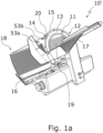
- the Figures 1a and 1b show isometric views of a disc cutting machine designed as an inclined cutting machine or a vertical cutting machine.
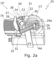
- the Figures 2a to 2c show a grinding device according to the invention in an installation position and a working position on the bevel cutting machine.
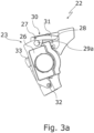
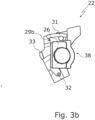
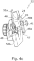
- the Figures 3a to 4d show different views of the grinding device.
- the Fig. 5 shows a stop plate of the disc cutting machine with recesses for receiving the noses of the grinding device.
- a disc cutting machine 10' designed as an oblique cutting machine is shown, to which a grinding device 22 according to the invention (cf. Fig. 2a ) can be attached.
- the disc cutting machine 10 ⁇ comprises a cutting device 11 in a machine housing 12.
- the cutting device 11 has a rotatably mounted circular blade 13.
- a cutting edge 14 of the circular blade 13 is covered by a blade protection ring 15 in a first section.
- the disc cutting machine 10 ⁇ comprises a stop plate 16 and a displaceably arranged carriage 17, via which a cutting material (not shown) is fed to the circular blade 13.
- the stop plate 16 is in the direction of the rotation axis RA (see Fig. 2a ) of the circular knife 13.
- the stop plate 16 is in an open position 18 at a distance from the circular blade 13 in the direction of the rotation axis RA of the circular blade 13.
- the cutting edge 14 of the circular blade 13 is freely accessible.
- a blade cover 19 serves to protect the circular blade 13 along its inner circumference.
- the blade protection ring 15 has an end 20 designed as a projection, which fits into a receptacle 43 of a grinding device 22 (see Fig. 4a ) is introduced.
- Fig. 1a also elongated recesses 53a, 53b on the front side of the stop plate 16 facing the carriage 17 for corresponding recesses 52a, 52b of the grinding device 22 (see Fig. 4c ).
- the elongated recesses 53a, 53b accommodate the bulges 52a, 52b, the recesses do not form a positive connection with the bulges.
- the bulges 52a, 52b can be circular in cross-section, as in the embodiment of Fig. 4c shown.
- a disc cutting machine 10" designed as a vertical cutting machine with the carriage 17, the stop plate 16 and the rotating circular knife 13, on which the grinding device 22 is also mounted
- the vertical cutting machine 10" is controlled via a dashboard 21 .
- the grinding device 22 For grinding the circular blade 13, which is mounted so as to be rotatable about the axis of rotation RA, the grinding device 22 is used, which is mounted in a Fig. 2a shown installation position 23 via a bracket 24 on the stop plate 16 of a disk cutting machine 10', as shown in Fig. 1a shown in the open position (cf. Fig. 1a ) is mounted.
- the grinding device 22 and the disc cutting machine 10 ⁇ together form a disc cutting system 25.
- the installation position 23 can be recognized in particular by the fact that a housing 26 for protecting the operating mechanism (not shown) of the grinding device 22 is pivoted away from the circular blade 13, while this housing 26 is in a working position (see Fig. 2c ) is pivoted towards the circular blade 13.
- a locking mechanism 27 with a locking pin 28 locks the grinding device 22 in the installation position 23.
- the locking mechanism 27 also serves to lock the grinding device 22 in a working position (see Fig. 2c ) to lock.
- the pivoting from the working position to the installation position 23 is carried out via a pivoting mechanism 30.
- the pivoting mechanism 30 has a guide 31 for guiding the grinding device 22 during pivoting.
- the housing 26 is pivoted about a rotary pin 32 of the pivoting mechanism.
- the pivoting movement of the grinding device 22 in the direction of the installation position 23 is stopped by a stop 33 as a buffer.
- the grinding device 22 has a handle 34 for moving a grinding stone 39 and a honing stone 40 (see Fig. 4a ) to the circular blade 13 of the disc cutting machine 10.
- the handle 34 is designed as a wheel 35 , which when rotated moves the grinding stone 39 and the honing stone 40 towards the circular blade 13 or away from the circular blade 13.
- the Grinding device 22 comprises a frame 36 which carries the described components.
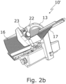
- Fig. 2b shows for comparison with Fig. 1a the bevel cutting machine 10 ⁇ with the carriage 17, the stop plate 16 and the circular knife 13, whereby the grinding device 22 is now mounted in the installation position 23 on the stop plate 16.
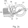
- the grinding device 22 assumes a working position 38 which is Fig. 2c
- the housing 26 is in comparison to the installation position 23 (see Fig. 2a ) towards the circular blade 13 and spaced from the stop 33.
- the housing 26 has been pivoted about the rotary pin 32 from the installation position 23 to the working position 38.
- the carriage 17 cannot be moved over the entire carriage stroke, as it could otherwise collide with the grinding device 22 during its movement.
- the carriage 17 covers a lower part of the cutting edge 14 of the circular blade 13.
- part of the circular blade 13 is also covered by the carriage 17.
- To lock the grinding device 22 in the installation position 23 is provided with a second locking receptacle 29b.
- Fig. 3a shows a side view of the grinding device 22 in the installation position 23.
- the housing 26 of the grinding device 22 rests against the stop 33.
- the locking mechanism 27 with the locking pin 28 locks the grinding device 22 in the installation position 23.
- the pivoting mechanism 30 with the guide 31 and the rotating pin 32 Also shown is the first locking receptacle 29a.
- Fig. 3b shows a side view of the grinding device 22 in the working position 38.
- the housing 26 is pivoted about the rotary pin 32 along the guide 31 and is spaced from the stop 33.
- the second locking receptacle 29b is also shown.
- the grinding device 22 has the grinding stone 39 for sharpening the circular knife 13 (see Fig. 2a ) and the whetstone 40 for deburring the circular blade 13, which are in Fig. 4a and Fig. 4b
- the grinding stone 39 and the honing stone 40 are connected by means of the wheel 35 to the circular knife 13 (see Fig. 2a ) is moved.
- the frame 36 of the grinding device 22 comprises cover plates 42a, 42b for covering the circular blade 13.
- the grinding stone 39 and the honing stone 40 are arranged in the circumferential direction of the circular blade 13 between such cover plates 42a, 42b of the frame 36.
- the holder 43 of the grinding device 22 is designed to hold the end 20 of the blade protection ring 15, which is designed as a projection (see Fig. 1a ) when the stop plate 16 is in the direction of the rotation axis RA of the circular blade 13 (see Fig. 1b ) has a predetermined distance from the circular blade 13.
- the receptacle 43 does not engage around the end 20 of the blade protection ring 15 if the distance between the stop plate 16 and the blade protection ring 15 in the direction of the axis of rotation RA of the circular blade 13 is smaller than the predetermined distance.
- the receptacle 43 is designed as a recess 44 in the grinding device 22 for inserting the end 20 of the blade protection ring 15.
- the bracket 24 for fastening the grinding device 22 to the stop plate 16 has a Fig. 4c shown, in particular U-shaped, plate holder 45 with a gap 46 for inserting the stop plate 16 into the gap 46 when sliding the grinding device 22 onto the stop plate 16.
- the threaded spindle 41 is located at the gap 46 of the plate holder 45.
- Protrusions 52a, 52b of the holder 24 engage in corresponding recesses 53a, 53b on the front of the stop plate 16 (see Fig. 1a ).
- the holder 24 of the grinding device 22 also has an insertion device 47 for positive insertion into the stop plate 16.
- the insertion device 47 comprises two lugs 48a, 48b, which fit into corresponding recesses on a rear side of the stop plate 16 (see Fig. 5 ) engage in a form-fitting manner.
- the insertion device 47 with the lugs 48a, 48b is formed on an inner side 49 of the gap 46 of the plate holder 45, on which the stop plate 16 is arranged in the assembled state of the grinding device 22.
- the lugs 48a, 48b have a tapering U-shape in the direction of insertion ER of the insertion device 47, as in Fig. 4d shown in detail.
- the recesses 50a, 50b of the stop plate 16 shown in FIG. 3c form-fittingly receive the lugs 48a, 48b of the insertion device.
- the recesses 50a, 50b are formed on a rear side 51 of the stop plate 16, which extends in the direction of the axis of rotation RA of the circular blade 13 (see Fig. 2a ) faces away from the carriage 17 of the disc cutting machine 10 ⁇ .
Landscapes
- Engineering & Computer Science (AREA)
- Mechanical Engineering (AREA)
- Life Sciences & Earth Sciences (AREA)
- Forests & Forestry (AREA)
- Food Science & Technology (AREA)
- Finish Polishing, Edge Sharpening, And Grinding By Specific Grinding Devices (AREA)
- Food-Manufacturing Devices (AREA)
Claims (13)
- Affûteuse (22) pour une machine de découpe en tranches (10`, 10") destinée à découper des tranches d'un produit à découper en particulier en forme de boudin, de préférence de produits alimentaires, l'affûteuse (22) comprenant une meule (39) destinée à aiguiser une lame circulaire (13) rotative et/ou mobile en rotation de la machine de découpe en tranches (10`, 10") et une pierre à aiguiser (40) destinée à ébavurer la lame circulaire (13), l'affûteuse (22) présentant une poignée (34) afin de déplacer la meule (39) et/ou la pierre à aiguiser (40) vers la lame circulaire (13), l'affûteuse (22) présentant un support (24) permettant la fixation à une plaque de butée (16) de la machine de découpe en tranches (10`, 10") et comportant un dispositif d'insertion (47) destiné à être inséré par complémentarité de forme dans la plaque de butée (16), le support (24) présentant un logement pour plaque (45) en forme de U comportant une fente (46) destinée à l'introduction de la plaque de butée (16) dans la fente (46) lors du coulissement de l'affûteuse (22) sur la plaque de butée (16), et l'affûteuse (22) présentant un cadre (36) destiné à recouvrir au moins une section partielle d'une arête de coupe (14) de la lame circulaire (13) et à faire pivoter l'affûteuse (22) d'une position d'installation (23) dans une position de travail (38),
caractérisée en cequ'un logement (43) de l'affûteuse (22) destiné à entourer par complémentarité de forme une extrémité (20) d'une bague de protection de lame (15) de la machine de découpe en tranches (10`, 10") est présent, le logement (43) étant réalisé pour entourer l'extrémité (20) de la bague de protection de lame (15) lorsque la plaque de butée (16) présente au moins une distance prédéterminée par rapport à la lame circulaire (13) dans la direction d'un axe de rotation (RA) de la lame circulaire (13), et pour ne pas entourer l'extrémité (20) de la bague de protection de lame (15) lorsque la distance entre la plaque de butée (16) et la bague de protection de lame (15) dans la direction de l'axe de rotation (RA) de la lame circulaire (13) est inférieure à la distance prédéterminée, en ce que le logement (43) est réalisé sous forme d'évidement (44) destiné à l'introduction de l'extrémité (20) de la bague de protection de lame (15),et en ce que le cadre (36) de l'affûteuse (22) comprend des plaques de recouvrement (42a, 42b) permettant de recouvrir l'arête de coupe (14) de la lame circulaire (13), la meule (39) et la pierre à aiguiser (40) étant disposées entre les plaques de recouvrement (42a, 42b). - Affûteuse (22) selon la revendication 1, caractérisée en ce que le dispositif d'insertion (47) présente au moins un ergot (48a, 48b), de préférence deux ergots (48a, 48b), destinés à venir en prise dans un renfoncement (50a, 50b) associé de la plaque de butée (16), l'au moins un ergot (48a, 48b) étant en particulier réalisé pour venir en prise dans un renfoncement (50a, 50b) sur une face arrière (51) de la plaque de butée (16), et la face arrière (51) de la plaque de butée (16) étant opposée à un chariot (17) de la machine de découpe en tranches (10`, 10") dans la direction de l'axe de rotation (RA) de la lame circulaire (13).
- Affûteuse (22) selon l'une des revendications précédentes, caractérisée par un mécanisme d'encliquetage (27) permettant d'encliqueter l'affûteuse (22) dans la position de travail (38) et/ou dans la position d'installation (23).
- Affûteuse (22) selon l'une des revendications précédentes, caractérisée par un mécanisme de pivotement (30) permettant de faire pivoter l'affûteuse (22) de la position de travail (38) dans la position d'installation (23).
- Affûteuse (22) selon la revendication 4, caractérisée par une butée (33) pour le mécanisme de pivotement (30).
- Affûteuse (22) selon l'une des revendications précédentes,
caractérisée en ce que le support (24) permettant de fixer l'affûteuse (22) sur une plaque de butée (16) de la machine de découpe en tranches (10', 10") présente une broche filetée (41) permettant de serrer la plaque de butée (16). - Affûteuse (22) selon l'une des revendications précédentes,
caractérisée en ce que le dispositif d'insertion (47) est réalisé sur la face intérieure (49) de la fente (46) du logement pour plaque (45). - Affûteuse (22) selon l'une des revendications précédentes,
caractérisée en ce que le dispositif d'insertion (47) présente une forme se rétrécissant, en particulier une forme en U, dans le sens d'insertion. - Affûteuse (22) selon l'une des revendications précédentes,
caractérisée en ce que la poignée (34) permettant de déplacer la meule (39) et/ou la pierre à aiguiser (40) vers la lame circulaire (13) de la machine de découpe en tranches (10`, 10") est réalisée sous forme de roue (35) du cadre (36) de l'affûteuse (22), la roue (35) étant réalisée pour déplacer, lors de la rotation, la meule (39) et/ou la pierre à aiguiser (40) vers la lame circulaire (13) de telle sorte qu'elles peuvent être disposées contre la lame circulaire (13), et/ou pour les éloigner de la lame circulaire (13). - Installation de découpe en tranches (25) comportant une machine de découpe en tranches (10`, 10") destinée à découper des tranches d'un produit à découper en particulier en forme de boudin, de préférence de produits alimentaires, comportant un boîtier de machine (12) qui supporte un moteur d'entraînement et une lame circulaire (13), rotative et/ou mobile en rotation, entraînée par le moteur d'entraînement, une arête de coupe (14) de la lame circulaire (13) étant recouverte dans une première section partielle par une bague de protection de lame (15), la machine de découpe en tranches (10`, 10") comprenant une plaque de butée (16) ainsi qu'un chariot (17) disposé de manière à pouvoir coulisser, par l'intermédiaire duquel le produit à découper est amené à la lame circulaire (13), la plaque de butée (16) pouvant être déplacée dans la direction de l'axe de rotation (RA) de la lame circulaire (13), et l'installation de découpe en tranches (25) présentant une affûteuse (22) selon l'une des revendications précédentes.
- Installation de découpe en tranches (25) selon la revendication 10, caractérisée en ce que la plaque de butée (16) de la machine de découpe en tranches (10`, 10") présente au moins un renfoncement (50a, 50b), en particulier deux renfoncements (50a, 50b), permettant de recevoir par complémentarité de forme le dispositif d'insertion (47) de l'affûteuse (22), le renfoncement (50a, 50b) étant de préférence réalisé sur une face arrière (51) de la plaque de butée (16), laquelle face arrière est opposée à un chariot (17) de la machine de découpe en tranches (10`, 10") dans la direction de l'axe de rotation (RA) de la lame circulaire (13).
- Installation de découpe en tranches (25) selon l'une des revendications 10 ou 11, caractérisée en ce que le cadre (36) présente, dans la direction de l'axe de rotation (RA) de la lame circulaire (13), une largeur telle que le cadre (36) recouvre toujours l'arête de coupe (14) de la lame circulaire (13) pendant le déplacement de la plaque de butée (16).
- Installation de découpe en tranches (25) selon l'une des revendications 10 à 12, caractérisée en ce que la plaque de butée (16) de la machine de découpe en tranches (10`, 10") peut être déplacée dans une position zéro dans laquelle la plaque de butée (16) et la bague de protection de lame (15) recouvrent ensemble complètement l'arête de coupe (14) de la lame circulaire (13), de telle sorte que la lame circulaire (13) ne découpe pas le produit à découper.
Priority Applications (2)
| Application Number | Priority Date | Filing Date | Title |
|---|---|---|---|
| EP21179802.0A EP4104969B1 (fr) | 2021-06-16 | 2021-06-16 | Appareil de rectification pour une machine à trancher pourvu de protection contre le contacte lors du montage |
| US17/837,113 US11738477B2 (en) | 2021-06-16 | 2022-06-10 | Whetting device for a slicer comprising a guard preventing accidental contact during mounting |
Applications Claiming Priority (1)
| Application Number | Priority Date | Filing Date | Title |
|---|---|---|---|
| EP21179802.0A EP4104969B1 (fr) | 2021-06-16 | 2021-06-16 | Appareil de rectification pour une machine à trancher pourvu de protection contre le contacte lors du montage |
Publications (2)
| Publication Number | Publication Date |
|---|---|
| EP4104969A1 EP4104969A1 (fr) | 2022-12-21 |
| EP4104969B1 true EP4104969B1 (fr) | 2024-11-06 |
Family
ID=76695471
Family Applications (1)
| Application Number | Title | Priority Date | Filing Date |
|---|---|---|---|
| EP21179802.0A Active EP4104969B1 (fr) | 2021-06-16 | 2021-06-16 | Appareil de rectification pour une machine à trancher pourvu de protection contre le contacte lors du montage |
Country Status (2)
| Country | Link |
|---|---|
| US (1) | US11738477B2 (fr) |
| EP (1) | EP4104969B1 (fr) |
Family Cites Families (12)
| Publication number | Priority date | Publication date | Assignee | Title |
|---|---|---|---|---|
| FR741648A (fr) * | 1933-02-16 | |||
| GB178913A (en) * | 1921-01-21 | 1922-04-21 | George Archie Smith | Improvements in or relating to means for sharpening the knives of food slicing machines |
| GB457379A (en) * | 1936-07-28 | 1936-11-26 | Alfred Vivian Griffiths | Improvements in or relating to sharpening devices for slicing machines employing circular knives |
| US2978848A (en) * | 1957-07-17 | 1961-04-11 | Armour & Co | Grinder for involute bacon knife |
| US3986304A (en) * | 1975-12-02 | 1976-10-19 | Hobart Corporation | Sharpener for commodity slicing machine |
| GB9815205D0 (en) * | 1998-07-15 | 1998-09-09 | Gec Avery Ltd | Sharpening agreement |
| DE19907028A1 (de) | 1999-01-25 | 2000-07-27 | Gebr Graef Gmbh & Co Kg | Schleifvorrichtung für eine Schneidemaschine für Lebensmittel |
| DE10300972A1 (de) | 2003-01-10 | 2004-07-22 | Yanar, Cozfin | Schleifvorrichtung für rotierend angetriebene Kreismesser |
| US8043142B2 (en) | 2005-08-26 | 2011-10-25 | Premark Feg L.L.C. | Sharpener carried by the product table of a food slicer |
| US7134937B1 (en) | 2005-12-19 | 2006-11-14 | Premark Feg L.L.C. | Food product slicer with knife sharpener and associated knife guard |
| ITMI20111122A1 (it) * | 2011-06-21 | 2012-12-22 | Slayer Blades S R L | Affilatoio universale per macchine affettatrici con lama a disco. |
| SE542842C2 (sv) * | 2019-03-13 | 2020-07-14 | Tore Eklund | Slip- och polerverktyg, verktygsuppsättning, samt tillsats för cirkulär skärklinga |
-
2021
- 2021-06-16 EP EP21179802.0A patent/EP4104969B1/fr active Active
-
2022
- 2022-06-10 US US17/837,113 patent/US11738477B2/en active Active
Also Published As
| Publication number | Publication date |
|---|---|
| US11738477B2 (en) | 2023-08-29 |
| EP4104969A1 (fr) | 2022-12-21 |
| US20220402157A1 (en) | 2022-12-22 |
Similar Documents
| Publication | Publication Date | Title |
|---|---|---|
| EP1642680B1 (fr) | Capot pour outil motorisé | |
| DE4204271A1 (de) | Schneidemaschine fuer lebensmittel | |
| EP1777047A1 (fr) | Couvercle de protection | |
| EP1642674A1 (fr) | Capot pour outil motorisé | |
| DE60304797T2 (de) | Werkzeug für Kreismesser | |
| WO1995032846A1 (fr) | Racle pour machine a decouper les aliments | |
| EP2844441B1 (fr) | Lame avec une eclusion de securisation | |
| DE102008033547A1 (de) | Schleif- und Schärfmaschine für Schneidklingen | |
| EP4104969B1 (fr) | Appareil de rectification pour une machine à trancher pourvu de protection contre le contacte lors du montage | |
| DE102005013363B4 (de) | Maschine zum Schärfen von Rotationsmessern | |
| EP0621821B1 (fr) | Scies mécaniques à lame avec dispositif anti-éclatement | |
| EP1882408B1 (fr) | Lame de coupe de plantes récoltées | |
| EP4104970B1 (fr) | Appareil de rectification pour machine à trancher pourvu d'aide au positionnement | |
| EP0201839B1 (fr) | Couteau à main | |
| CH706727A2 (de) | Gerät zum Bearbeiten von Lebensmitteln. | |
| DE102006054929B3 (de) | Vorrichtung zum Auftrennen eines Schmuck- oder Fingerringes | |
| DE9113614U1 (de) | Schneidgerät | |
| EP1840229B1 (fr) | Dispositif de transport pour lame lisse, tout comme procédé de montage et de démontage d'une lame lisse | |
| DE1204965B (de) | Scheibenschneidmaschine fuer Fleisch- und Wurstwaren | |
| EP0090064B1 (fr) | Trancheuse ayant un dispositif d'affûtage pour le couteau circulaire | |
| DE10300972A1 (de) | Schleifvorrichtung für rotierend angetriebene Kreismesser | |
| DE602004000870T2 (de) | Schneidmaschine mit Schleifvorrichtung | |
| DE3214464A1 (de) | Aufschnittschneidemaschine mit einem schleifzeug fuer das rotierende rundmesser | |
| DE1657218C3 (de) | Aufschnittschneidmaschine | |
| DE4334209C2 (de) | Küchenmaschine |
Legal Events
| Date | Code | Title | Description |
|---|---|---|---|
| PUAI | Public reference made under article 153(3) epc to a published international application that has entered the european phase |
Free format text: ORIGINAL CODE: 0009012 |
|
| STAA | Information on the status of an ep patent application or granted ep patent |
Free format text: STATUS: THE APPLICATION HAS BEEN PUBLISHED |
|
| AK | Designated contracting states |
Kind code of ref document: A1 Designated state(s): AL AT BE BG CH CY CZ DE DK EE ES FI FR GB GR HR HU IE IS IT LI LT LU LV MC MK MT NL NO PL PT RO RS SE SI SK SM TR |
|
| STAA | Information on the status of an ep patent application or granted ep patent |
Free format text: STATUS: REQUEST FOR EXAMINATION WAS MADE |
|
| 17P | Request for examination filed |
Effective date: 20230503 |
|
| RBV | Designated contracting states (corrected) |
Designated state(s): AL AT BE BG CH CY CZ DE DK EE ES FI FR GB GR HR HU IE IS IT LI LT LU LV MC MK MT NL NO PL PT RO RS SE SI SK SM TR |
|
| GRAP | Despatch of communication of intention to grant a patent |
Free format text: ORIGINAL CODE: EPIDOSNIGR1 |
|
| STAA | Information on the status of an ep patent application or granted ep patent |
Free format text: STATUS: GRANT OF PATENT IS INTENDED |
|
| RIC1 | Information provided on ipc code assigned before grant |
Ipc: B26D 7/12 20060101ALI20240605BHEP Ipc: B24B 3/36 20060101ALI20240605BHEP Ipc: B24B 3/46 20060101AFI20240605BHEP |
|
| INTG | Intention to grant announced |
Effective date: 20240702 |
|
| GRAS | Grant fee paid |
Free format text: ORIGINAL CODE: EPIDOSNIGR3 |
|
| GRAA | (expected) grant |
Free format text: ORIGINAL CODE: 0009210 |
|
| STAA | Information on the status of an ep patent application or granted ep patent |
Free format text: STATUS: THE PATENT HAS BEEN GRANTED |
|
| AK | Designated contracting states |
Kind code of ref document: B1 Designated state(s): AL AT BE BG CH CY CZ DE DK EE ES FI FR GB GR HR HU IE IS IT LI LT LU LV MC MK MT NL NO PL PT RO RS SE SI SK SM TR |
|
| REG | Reference to a national code |
Ref country code: GB Ref legal event code: FG4D Free format text: NOT ENGLISH |
|
| REG | Reference to a national code |
Ref country code: CH Ref legal event code: EP |
|
| REG | Reference to a national code |
Ref country code: DE Ref legal event code: R096 Ref document number: 502021005688 Country of ref document: DE |
|
| REG | Reference to a national code |
Ref country code: IE Ref legal event code: FG4D Free format text: LANGUAGE OF EP DOCUMENT: GERMAN |
|
| REG | Reference to a national code |
Ref country code: LT Ref legal event code: MG9D |
|
| REG | Reference to a national code |
Ref country code: NL Ref legal event code: MP Effective date: 20241106 |
|
| PG25 | Lapsed in a contracting state [announced via postgrant information from national office to epo] |
Ref country code: HR Free format text: LAPSE BECAUSE OF FAILURE TO SUBMIT A TRANSLATION OF THE DESCRIPTION OR TO PAY THE FEE WITHIN THE PRESCRIBED TIME-LIMIT Effective date: 20241106 Ref country code: IS Free format text: LAPSE BECAUSE OF FAILURE TO SUBMIT A TRANSLATION OF THE DESCRIPTION OR TO PAY THE FEE WITHIN THE PRESCRIBED TIME-LIMIT Effective date: 20250306 Ref country code: PT Free format text: LAPSE BECAUSE OF FAILURE TO SUBMIT A TRANSLATION OF THE DESCRIPTION OR TO PAY THE FEE WITHIN THE PRESCRIBED TIME-LIMIT Effective date: 20250306 |
|
| PG25 | Lapsed in a contracting state [announced via postgrant information from national office to epo] |
Ref country code: NL Free format text: LAPSE BECAUSE OF FAILURE TO SUBMIT A TRANSLATION OF THE DESCRIPTION OR TO PAY THE FEE WITHIN THE PRESCRIBED TIME-LIMIT Effective date: 20241106 Ref country code: FI Free format text: LAPSE BECAUSE OF FAILURE TO SUBMIT A TRANSLATION OF THE DESCRIPTION OR TO PAY THE FEE WITHIN THE PRESCRIBED TIME-LIMIT Effective date: 20241106 |
|
| PG25 | Lapsed in a contracting state [announced via postgrant information from national office to epo] |
Ref country code: BG Free format text: LAPSE BECAUSE OF FAILURE TO SUBMIT A TRANSLATION OF THE DESCRIPTION OR TO PAY THE FEE WITHIN THE PRESCRIBED TIME-LIMIT Effective date: 20241106 |
|
| PG25 | Lapsed in a contracting state [announced via postgrant information from national office to epo] |
Ref country code: ES Free format text: LAPSE BECAUSE OF FAILURE TO SUBMIT A TRANSLATION OF THE DESCRIPTION OR TO PAY THE FEE WITHIN THE PRESCRIBED TIME-LIMIT Effective date: 20241106 |
|
| PG25 | Lapsed in a contracting state [announced via postgrant information from national office to epo] |
Ref country code: NO Free format text: LAPSE BECAUSE OF FAILURE TO SUBMIT A TRANSLATION OF THE DESCRIPTION OR TO PAY THE FEE WITHIN THE PRESCRIBED TIME-LIMIT Effective date: 20250206 |
|
| PG25 | Lapsed in a contracting state [announced via postgrant information from national office to epo] |
Ref country code: LV Free format text: LAPSE BECAUSE OF FAILURE TO SUBMIT A TRANSLATION OF THE DESCRIPTION OR TO PAY THE FEE WITHIN THE PRESCRIBED TIME-LIMIT Effective date: 20241106 Ref country code: GR Free format text: LAPSE BECAUSE OF FAILURE TO SUBMIT A TRANSLATION OF THE DESCRIPTION OR TO PAY THE FEE WITHIN THE PRESCRIBED TIME-LIMIT Effective date: 20250207 |
|
| PG25 | Lapsed in a contracting state [announced via postgrant information from national office to epo] |
Ref country code: PL Free format text: LAPSE BECAUSE OF FAILURE TO SUBMIT A TRANSLATION OF THE DESCRIPTION OR TO PAY THE FEE WITHIN THE PRESCRIBED TIME-LIMIT Effective date: 20241106 |
|
| PG25 | Lapsed in a contracting state [announced via postgrant information from national office to epo] |
Ref country code: RS Free format text: LAPSE BECAUSE OF FAILURE TO SUBMIT A TRANSLATION OF THE DESCRIPTION OR TO PAY THE FEE WITHIN THE PRESCRIBED TIME-LIMIT Effective date: 20250206 |
|
| PG25 | Lapsed in a contracting state [announced via postgrant information from national office to epo] |
Ref country code: SM Free format text: LAPSE BECAUSE OF FAILURE TO SUBMIT A TRANSLATION OF THE DESCRIPTION OR TO PAY THE FEE WITHIN THE PRESCRIBED TIME-LIMIT Effective date: 20241106 |
|
| PGFP | Annual fee paid to national office [announced via postgrant information from national office to epo] |
Ref country code: DE Payment date: 20250618 Year of fee payment: 5 |
|
| PG25 | Lapsed in a contracting state [announced via postgrant information from national office to epo] |
Ref country code: DK Free format text: LAPSE BECAUSE OF FAILURE TO SUBMIT A TRANSLATION OF THE DESCRIPTION OR TO PAY THE FEE WITHIN THE PRESCRIBED TIME-LIMIT Effective date: 20241106 |
|
| PG25 | Lapsed in a contracting state [announced via postgrant information from national office to epo] |
Ref country code: EE Free format text: LAPSE BECAUSE OF FAILURE TO SUBMIT A TRANSLATION OF THE DESCRIPTION OR TO PAY THE FEE WITHIN THE PRESCRIBED TIME-LIMIT Effective date: 20241106 |
|
| PGFP | Annual fee paid to national office [announced via postgrant information from national office to epo] |
Ref country code: FR Payment date: 20250618 Year of fee payment: 5 |
|
| PG25 | Lapsed in a contracting state [announced via postgrant information from national office to epo] |
Ref country code: RO Free format text: LAPSE BECAUSE OF FAILURE TO SUBMIT A TRANSLATION OF THE DESCRIPTION OR TO PAY THE FEE WITHIN THE PRESCRIBED TIME-LIMIT Effective date: 20241106 |
|
| PGFP | Annual fee paid to national office [announced via postgrant information from national office to epo] |
Ref country code: AT Payment date: 20250721 Year of fee payment: 5 |
|
| PG25 | Lapsed in a contracting state [announced via postgrant information from national office to epo] |
Ref country code: SK Free format text: LAPSE BECAUSE OF FAILURE TO SUBMIT A TRANSLATION OF THE DESCRIPTION OR TO PAY THE FEE WITHIN THE PRESCRIBED TIME-LIMIT Effective date: 20241106 |
|
| PG25 | Lapsed in a contracting state [announced via postgrant information from national office to epo] |
Ref country code: CZ Free format text: LAPSE BECAUSE OF FAILURE TO SUBMIT A TRANSLATION OF THE DESCRIPTION OR TO PAY THE FEE WITHIN THE PRESCRIBED TIME-LIMIT Effective date: 20241106 |
|
| REG | Reference to a national code |
Ref country code: DE Ref legal event code: R097 Ref document number: 502021005688 Country of ref document: DE |
|
| PG25 | Lapsed in a contracting state [announced via postgrant information from national office to epo] |
Ref country code: SE Free format text: LAPSE BECAUSE OF FAILURE TO SUBMIT A TRANSLATION OF THE DESCRIPTION OR TO PAY THE FEE WITHIN THE PRESCRIBED TIME-LIMIT Effective date: 20241106 |
|
| PLBE | No opposition filed within time limit |
Free format text: ORIGINAL CODE: 0009261 |
|
| STAA | Information on the status of an ep patent application or granted ep patent |
Free format text: STATUS: NO OPPOSITION FILED WITHIN TIME LIMIT |
|
| 26N | No opposition filed |
Effective date: 20250807 |
|
| PGFP | Annual fee paid to national office [announced via postgrant information from national office to epo] |
Ref country code: IT Payment date: 20250630 Year of fee payment: 5 |
|
| REG | Reference to a national code |
Ref country code: CH Ref legal event code: H13 Free format text: ST27 STATUS EVENT CODE: U-0-0-H10-H13 (AS PROVIDED BY THE NATIONAL OFFICE) Effective date: 20260127 |
|
| PG25 | Lapsed in a contracting state [announced via postgrant information from national office to epo] |
Ref country code: MC Free format text: LAPSE BECAUSE OF FAILURE TO SUBMIT A TRANSLATION OF THE DESCRIPTION OR TO PAY THE FEE WITHIN THE PRESCRIBED TIME-LIMIT Effective date: 20241106 |
|
| PG25 | Lapsed in a contracting state [announced via postgrant information from national office to epo] |
Ref country code: LU Free format text: LAPSE BECAUSE OF NON-PAYMENT OF DUE FEES Effective date: 20250616 |
|
| GBPC | Gb: european patent ceased through non-payment of renewal fee |
Effective date: 20250616 |
|
| REG | Reference to a national code |
Ref country code: BE Ref legal event code: MM Effective date: 20250630 |
|
| PG25 | Lapsed in a contracting state [announced via postgrant information from national office to epo] |
Ref country code: GB Free format text: LAPSE BECAUSE OF NON-PAYMENT OF DUE FEES Effective date: 20250616 |
|
| PG25 | Lapsed in a contracting state [announced via postgrant information from national office to epo] |
Ref country code: IE Free format text: LAPSE BECAUSE OF NON-PAYMENT OF DUE FEES Effective date: 20250616 |
|
| PG25 | Lapsed in a contracting state [announced via postgrant information from national office to epo] |
Ref country code: BE Free format text: LAPSE BECAUSE OF NON-PAYMENT OF DUE FEES Effective date: 20250630 |
|
| PG25 | Lapsed in a contracting state [announced via postgrant information from national office to epo] |
Ref country code: CH Free format text: LAPSE BECAUSE OF NON-PAYMENT OF DUE FEES Effective date: 20250630 |