EP4104977B1 - Robot avec fixations de connexion d'assemblage complémentaire - Google Patents
Robot avec fixations de connexion d'assemblage complémentaire Download PDFInfo
- Publication number
- EP4104977B1 EP4104977B1 EP22187367.2A EP22187367A EP4104977B1 EP 4104977 B1 EP4104977 B1 EP 4104977B1 EP 22187367 A EP22187367 A EP 22187367A EP 4104977 B1 EP4104977 B1 EP 4104977B1
- Authority
- EP
- European Patent Office
- Prior art keywords
- robotic arm
- protrusion
- receptacle
- fastening
- fastening element
- Prior art date
- Legal status (The legal status is an assumption and is not a legal conclusion. Google has not performed a legal analysis and makes no representation as to the accuracy of the status listed.)
- Active
Links
Images


Classifications
-
- B—PERFORMING OPERATIONS; TRANSPORTING
- B25—HAND TOOLS; PORTABLE POWER-DRIVEN TOOLS; MANIPULATORS
- B25J—MANIPULATORS; CHAMBERS PROVIDED WITH MANIPULATION DEVICES
- B25J9/00—Program-controlled manipulators
- B25J9/02—Program-controlled manipulators characterised by movement of the arms, e.g. cartesian coordinate type
- B25J9/04—Program-controlled manipulators characterised by movement of the arms, e.g. cartesian coordinate type by rotating at least one arm, excluding the head movement itself, e.g. cylindrical coordinate type or polar coordinate type
- B25J9/041—Cylindrical coordinate type
- B25J9/042—Cylindrical coordinate type comprising an articulated arm
-
- B—PERFORMING OPERATIONS; TRANSPORTING
- B25—HAND TOOLS; PORTABLE POWER-DRIVEN TOOLS; MANIPULATORS
- B25J—MANIPULATORS; CHAMBERS PROVIDED WITH MANIPULATION DEVICES
- B25J17/00—Joints
-
- B—PERFORMING OPERATIONS; TRANSPORTING
- B25—HAND TOOLS; PORTABLE POWER-DRIVEN TOOLS; MANIPULATORS
- B25J—MANIPULATORS; CHAMBERS PROVIDED WITH MANIPULATION DEVICES
- B25J19/00—Accessories fitted to manipulators, e.g. for monitoring, for viewing; Safety devices combined with or specially adapted for use in connection with manipulators
- B25J19/007—Means or methods for designing or fabricating manipulators
-
- B—PERFORMING OPERATIONS; TRANSPORTING
- B25—HAND TOOLS; PORTABLE POWER-DRIVEN TOOLS; MANIPULATORS
- B25J—MANIPULATORS; CHAMBERS PROVIDED WITH MANIPULATION DEVICES
- B25J9/00—Program-controlled manipulators
- B25J9/0009—Constructional details, e.g. manipulator supports, bases
-
- B—PERFORMING OPERATIONS; TRANSPORTING
- B25—HAND TOOLS; PORTABLE POWER-DRIVEN TOOLS; MANIPULATORS
- B25J—MANIPULATORS; CHAMBERS PROVIDED WITH MANIPULATION DEVICES
- B25J9/00—Program-controlled manipulators
- B25J9/02—Program-controlled manipulators characterised by movement of the arms, e.g. cartesian coordinate type
- B25J9/04—Program-controlled manipulators characterised by movement of the arms, e.g. cartesian coordinate type by rotating at least one arm, excluding the head movement itself, e.g. cylindrical coordinate type or polar coordinate type
-
- B—PERFORMING OPERATIONS; TRANSPORTING
- B25—HAND TOOLS; PORTABLE POWER-DRIVEN TOOLS; MANIPULATORS
- B25J—MANIPULATORS; CHAMBERS PROVIDED WITH MANIPULATION DEVICES
- B25J9/00—Program-controlled manipulators
- B25J9/08—Program-controlled manipulators characterised by modular constructions
Definitions
- the present invention relates to a robot comprising a first assembly and a second assembly, wherein the first assembly includes a bearing through which the second assembly can be moved relative to the first assembly.
- the invention further relates to a method for assembling two assemblies, in particular two robot arms, of a robot.
- bearings often need to be inserted and installed during assembly. This results in a complex assembly process with many individual parts that must be precisely aligned with one another.
- the bearings can be permanently integrated into one of the two assemblies.
- this requires very precise relative positioning of the assemblies, with the rotation axes in the various assemblies in particular having to be precisely aligned with one another. This also makes assembly difficult.
- the invention aims to simplify the assembly of a robot while still ensuring high precision in the alignment of the components that can be moved relative to one another.
- the invention provides a robot with a first assembly and a second assembly, wherein at least one bearing is provided in the first assembly, by means of which the second assembly is movable relative to the first assembly, wherein, according to the invention, the at least one bearing comprises a first fastening element and the second assembly comprises a second fastening element, wherein the first and second fastening elements are connected to one another, in particular in a detachable fastening, and wherein the first and second fastening elements are designed to be complementary in some areas.
- Each assembly can be provided as a pre-assembled component and can be quickly and easily combined into an overall assembly by means of the fastening elements.
- the fastening via the fastening elements which are complementary in at least some areas, enables a rigid and A play-free bearing is provided for the relative movement of the assemblies, which also enables precise alignment of the assemblies to one another.
- the partially complementary fastening elements eliminate the need for complex alignment of the two assemblies or the individual fastening elements, as the complementary design determines the relative positions of the fastening elements. This also enables self-centering of the fastening elements and thus the assemblies, especially when the bearing is a pivot bearing around a specific axis.
- the bearing is designed such that the first fastening element is rotatably mounted in the first assembly.
- this rotatable bearing can be provided with a drive so that the second assembly can be rotated relative to the first assembly in a controlled manner.
- a sensor can also be provided in the bearing, which provides a feedback signal, particularly regarding the relative rotation of the assemblies, to a control unit.
- the first and second fastening elements can be inserted into one another.
- the fastening elements can be inserted into one another until the complementary surfaces come into contact with each other.
- a stop can be provided that limits the insertion in the desired position.
- the first or second fastening element forms a receptacle and the other of the first and second fastening elements forms a projection, wherein the projection is inserted into the receptacle for fastening in an insertion direction.
- the complementary shape of the projection and the receptacle enables a play-free fit and precise positioning of the fastening elements.
- the first fastening element forms a receptacle and the second fastening element forms a projection.
- the second fastening element forms a receptacle and the first fastening element forms a projection.
- the projection projects in particular beyond a side or inner surface of the respective assembly, wherein in other embodiments the projection can also be provided in a recessed region.
- a preload element is provided, with which a preload can be applied to the projection in the insertion direction.
- the preload element is a preload plate, a preload bushing, or a preload bracket, which acts with a preload on the projection.
- the preload can be achieved, for example, by elastic elements, Screws or clips can be provided.
- the preloading element can complete the complementary shape of the receptacle, so that the receptacle and preloading element are essentially complementary to the projection all the way around.
- the preloading element in particular, enables precise positioning and secure retention of the fastening elements relative to one another.
- the receptacle can be a guide and the projection a rail.
- the complementary shape can, for example, be only in the plane perpendicular to the insertion direction, allowing free positioning along the insertion direction.
- a stop or another, equally complementary shape can be provided that clearly defines the positioning between the guide and the rail in the insertion direction.
- the projection is designed to be partially circular, at least in part, and the receptacle is designed to be partially circular, at least in part.
- the translational positioning between the fastening elements or assemblies is primarily defined, although fine rotational adjustment may still be possible.
- a stop can also be provided which additionally determines the rotational position.
- the stop can in particular be formed by a contact surface which extends deviating from the circumferential direction of the circular segment, for example by a surface in the tangential direction which directly adjoins the circular segment.
- the projection can be conical in the insertion direction. This allows for easy insertion of the projection into a correspondingly designed, complementary receptacle and secure seating of the projection in the receptacle once the two are fully seated. Furthermore, the position of the projection in the receptacle is precisely defined.
- the first assembly is a first robot arm
- the second assembly is a second robot arm
- the second robot arm is pivotally connected to the first robot arm about a pivot axis extending in the axial direction of the bearings.
- the first assembly or second assembly can also be a base or gripper of a robot
- the other of the first and second assemblies can be a robot arm, wherein the assemblies are each connected to one another in a relatively rotatable or pivotable manner. It is thus possible to use the detachable fastening according to the invention between all components or assemblies of a robot, wherein it is advantageously used on the axes of the robot.
- the fastening elements can be inserted into each other essentially orthogonally to the pivot axis. This enables space-saving and ergonomic assembly of the robot arms.
- the at least one bearing comprises at least one shaft rotatably mounted in the first robot arm about the pivot axis, wherein the first fastening element is fastened to the shaft or is designed integrally and in one piece with it, and the second fastening element is provided in the second robot arm.
- the first fastening element can be rotated with the shaft, whereby a movement of the second robot arm relative to the first robot arm can be enabled or effected.
- the rotatably mounted shaft can in particular be driven and/or provided with a rotation sensor, so that a controlled movement of the robot arms relative to one another is possible.
- the first fastening element and its projection can in particular be formed by the shaft if the receptacle provides a shape that is at least partially complementary to the shaft. This is particularly useful for large shaft diameters and hollow shafts, since the frictional connection can then reliably prevent relative rotation between the shaft and the receptacle.
- the robot arm is formed at one end with two jaws extending parallel and spaced apart, with the second robot arm mounted between these jaws and rotatably mounted shafts provided coaxially in both jaws.
- an area is provided between the jaws in which the second robot arm can be arranged and secured.
- a first fastening element is provided on each of the rotatably mounted shafts, which can engage with a fastening element on either side of the second robot arm.
- one or both of the shafts can be displaced in the axial direction in order to apply a preload to the respective shaft bearing.
- Each shaft can be statically indeterminately mounted with only one pivot bearing, so that a statically determinately mounted rotating body, comprising the two shafts and the second robot arm, is only formed by the provision of the second robot arm.
- the second robot arm and the shafts can thus form a common rotating body.
- the shafts can therefore each be mounted with only one bearing, and a specific bearing for the shafts is only possible by inserting and fastening the second robot arm.
- statically determinate bearing of both shafts is also possible, each with two pivot bearings, or a double-row pivot bearing, in particular with two sets of rolling elements arranged axially next to one another, e.g. in the form of a double angular contact ball bearing.
- the second robot arm is formed at one end with two jaws extending parallel and spaced apart, wherein the first robot arm is mounted between these jaws and the two ends of at least one shaft rotatably mounted in the first robot arm are provided coaxially on both outer sides of the first robot arm.
- the shaft rotatably mounted in the first robot arm can be designed integrally or comprise two shafts provided independently of one another on the respective two outer sides of the robot arm. In the latter case, a statically determined mounting of the shafts can only be achieved by attaching the shafts to the second robot arm.
- the at least one shaft can be designed as a hollow shaft, and at least one cable and/or at least one fastening screw can be routed through the interior of the hollow shaft.
- This enables a compact design and also protects the cables, which can be used to control the various motors, read sensors, and/or supply and control an end effector.
- the present invention thus enables easy adjustment of the bearing preload. Furthermore, the inventive design avoids any restriction of rotational movement.
- the mounting of the assemblies is maintenance-free and can be easily disassembled and reassembled for maintenance of other components. Furthermore, a bearing preload can be adjusted, which then remains constant over a long service life.
- the mounting of the assemblies to one another according to the invention is also characterized by high rigidity.
- the first and/or second assembly is advantageously designed in a plate construction, in which several parallel plates are fastened to one another with spacers.
- the spacers can in particular be provided by further plates arranged orthogonally to the parallel plates.
- the parallel plates and the plates arranged orthogonally thereto are connected with a finger interlock.
- two plates can be fastened parallel to one another to spacers, wherein the fastening elements are then each provided axially outside in or on the plates.
- the assembly is designed with jaws extending at a distance, four parallel plates can be provided, which form the respective lateral boundaries of the jaws.
- the fastening elements can then each be provided in or on the inside of the inner plates.
- the jaws can also be formed by only one plate each.
- Cover elements are used to cover the open sides between the plates.
- the covers are arranged orthogonally to the plates.
- the plates can thus be used to define both the outer and inner contours of the assemblies, particularly in the form of robot arms.
- the invention further relates to a method for assembling two assemblies, in particular two robot arms, of a robot, wherein a first assembly is provided with a projection and a second assembly is provided with a receptacle, wherein either the projection is rotatable relative to the first assembly or the receptacle is rotatable relative to the second assembly about a pivot axis.
- the projection is then inserted into the receptacle in a linear insertion direction, and the projection is secured in the receptacle.
- the projection can be secured in the receptacle, in particular, by means of screws extending orthogonally to the insertion direction.
- circular openings or bores provided in the receptacle and in the projection are aligned with each other.
- a stop or other complementary fastening element can be used for alignment.
- securing the projection in the receptacle involves preloading in the insertion direction.
- the projection can be designed to complement the receptacle, and the preload can press the complementary components together to ensure a secure fit in a predefined position.
- the preload can achieve zero backlash.
- the assemblies can be provided preassembled for the method according to the invention, so that only pushing and connecting the assemblies together is necessary for assembly.
- the bearings for the pivot axis can, in particular, be provided preloaded for this purpose or, alternatively, can be preloaded separately after connecting the projection, in particular in the form of a rail, to the guide, in particular in the form of a receptacle.
- the Fig. 1 The robot 1 shown has several assemblies fastened to one another, namely a base 2 which can be rotated about the vertical axis, a swivel arm 3, an upper support arm 4, a lower support arm 5 and an articulated arm 6.
- the aforementioned robot arms 3, 4, 5, 6 are arranged in series according to a serial kinematics.
- the robot 1 shown is a 6-axis robot.
- the vertical axis for rotating the base 2 represents a first axis of the robot 1.
- a first joint 7 is provided between the base 2 and the swivel arm 3, which defines a second axis of the robot 1.
- a second joint 7 is provided between the swivel arm 3 and the upper support arm 4, which defines a third axis of the robot 1.
- a third joint 9 is provided between the upper support arm 4 and a lower support arm 5, which defines a fourth axis of the robot 1.
- the axis of rotation of the third joint 9 is in the direction of extension of the support arm 4, 5, so that the support arm 4, 5 is rotatable.
- a fourth joint 10 is provided between the lower support arm 5 and the articulated arm 6, which defines a fifth axis of the robot 1.
- An end effector in the form of a gripper (not shown) or another working element can be rotated relative to the articulated arm 6 about a sixth axis of the robot 1.
- the first and second joints 7, 8 enable pivoting of the swivel arm 3 and support arm 4, 5 about the respective, essentially horizontal second and third axes of the robot 1.
- the drive motors of the third and/or fourth joints 9, 10 are provided directly or via a gear at the joints, as in a purely serial kinematics system.
- the gear can be a drive belt.
- the drive movements for the first joint 7 and the second joint 8 are transmitted via four-bar chains 11, 12, 13 and 14, respectively.
- the first four-bar linkage 11 and the second four-bar linkage 12 are arranged in series to transmit a drive movement to the swivel arm 3 so that it can be swivelled relative to the base 2.
- the first four-bar linkage 11 has a Fig. 1 Hidden in the base 2 is a first crank, which can be pivoted by means of a first drive motor and is articulated to the coupler 15, and accordingly drives the coupler 15 of the first four-bar chain 11.
- the coupler 15 is articulated to the rocker 16 of the first four-bar chain 11 and drives it.
- the rocker 16 simultaneously forms the crank of the second four-bar chain 12 and is articulated to the coupler 17 of the second four-bar chain 12 and drives it.
- the rocker 18 of the second four-bar chain 12 is rigidly connected to the pivot arm 3 and rotates with it during its pivoting movement.
- the rocker 18 and the pivot arm 3 can be formed as one piece.
- the rocker arm 18 and the pivot arm 3 form a rocker relative to the first joint 7.
- the crank of the first four-bar linkage 11 can be flanged to a motor or gearbox in the base 2 via a drive shaft, so that it cannot be displaced in the axial direction.
- the gearbox can also be a drive belt or similar device.
- the rocker arm 16 can also be mounted in the base 2 so that it cannot be displaced axially.
- the bearing of the rocker arm 18 in the joint 7 can also be immovable in the axial direction.
- the drive movement for pivoting the support arm 4, 5 relative to the swivel arm 3 is transmitted by the third four-bar linkage chain 13 and the fourth four-bar linkage chain 14 from a second drive motor in the base 2 to the support arm 4, 5.
- the second drive motor drives a drive shaft arranged within the base 2 and thus not in the Fig. 1
- the crank of the third four-bar linkage 13 is pivoted, which is pivotally connected to the coupling 19 of the third four-bar linkage 13 and drives it.
- the coupling 19 is pivotally connected to the rocker 20 of the third four-bar linkage 13 and drives it.
- the rocker 20 is simultaneously the crank of the fourth four-bar linkage 14, which is pivotally connected to the coupling 21 of the fourth four-bar linkage 14 and drives it.
- the rocker 22 and the upper support arm 4 are rigidly connected in the form of a rocker with respect to the second linkage 7.
- the rocker 22 of the fourth four-bar linkage 14 is, in particular, formed integrally with the upper support arm 5.
- the crank of the third four-bar linkage 13 can be flanged immovably in the axial direction to a motor or gearbox in the base 2 via a drive shaft.
- the gearbox can also be a drive belt. or similar.
- the rocker arm 20 can be mounted axially immovably in the pivot arm 3.
- the mounting of the rocker arm 22 in the second joint 8 can also be axially immovable.
- the lower support arm 5 forms a first assembly which is connected to a second assembly in the form of the articulated arm 6 according to an embodiment of the robot 1 according to the invention, so that the articulated arm 6 can be pivoted in the lower support arm 5 about a pivot axis in the axial direction A.
- the lower support arm 5 has outer jaws 22, 23, in each of which a bearing 24, 25 is provided, which enables a first fastening element 26, 27 to be rotated about the pivot axis in the axial direction A.
- the first fastening element 26, 27 forms a projection 28, 29.
- the articulated arm 6 has, on each of its outer sides in the axial direction A, a second fastening element 30, 31, which is designed as a receptacle 32, 33.
- the first fastening element 26, 27 is designed in the region of the projection 28, 29 to be complementary to the receptacle 32, 33 of the second fastening element 30, 31.
- the projection 28, 29 can thus be arranged with a precise fit in the receptacle 32, 33 in order to connect the articulated arm 6 to the lower support arm 5, as shown in Fig. 3 shown.
- the first fastening element 26, 27 is arranged on a shaft 34, 35, which is rotatably mounted in the jaw 22, 23 of the lower support arm 5.
- the shafts 34, 35 are coaxially aligned with one another in the axial direction A and are rotatable.
- Each of the shafts 34, 35 is mounted with a pivot bearing 36, 37, in particular an angular contact bearing, near the respective axial outer side of the respective jaw 22, 23.
- a cylindrical opening 38, 39 is provided, through which the shaft 34, 35 projects axially towards the interior of the jaws 22, 23.
- the first fastening element 26, 27 is fastened to the axially inner end of the shaft 34, 35, in particular by screwing through the Fig. 5 illustrated circular openings 40, which are provided along the circumference of the end face of the shaft 34, 35 in the shaft 34, 35 and in the first fastening element 26, 27.
- a preloading element 41 in the form of a preloading plate is provided by means of screws on the articulated arm 6, so that the first fastening element 26, 27 is pressed in the insertion direction E into the receptacles 32, 33 of the second fastening element 30, 31.
- the preloading element 41 is in contact with the end faces of the projections 28, 29, wherein in particular a complementary configuration, for example in the form of a step, can be provided. so that not only force is applied to the projections 28, 29 in the insertion direction E, but also securing and/or preloading of the projections 28, 29 in the axial direction A is ensured.
- a bearing bush 42, 43 can be provided, which determines the position of the pivot bearings 36, 37 at least in the axial direction A.
- the position of the bearing bush 42, 43 can be adjusted in the axial direction A in order to adjust the preload of the pivot bearings 36, 37.
- the shafts 34, 35 together with the articulated arm 6 form an integrally rotatable unit.
- the preload in the axial direction A can be adjusted by adjusting the axial position of the bearing bush 42, 43 via screws 44, 45 with which the bearing bush 42, 43 is fastened to the lower support arm 5.
- the bearing bush 42, 43 can be provided only on one side of the lower support arm 5, whereby on the other side the pivot bearing 36 can be received directly in the support arm 5 and cannot be adjusted in position.
- a fastening screw 46, 47 can also be provided, which extends centrally through the shaft 34, 35 and is screwed into the second fastening element 30, 31. This makes it possible to provide an axially play-free and secure connection between the shaft 34, 35, the first fastening element 26, 27 and the second fastening element 30, 31.
- the fastening screw 46, 47 is guided through an opening 48, 49 in the first fastening element 26, 27.
- the first fastening element 26, 27 further has a circumferential web 50, 51 which has an inner diameter corresponding to the outer diameter of the axially inner end of the shaft 24, 25 and thus promotes the secure connection of the shaft 24, 25 to the first fastening element 26, 27.
- connection of the lower support arm 5 and the articulated arm 6 is thus designed such that the outer assembly in the form of the lower support arm 5 has a first fastening element 26, 27 with a projection 28, 29, each of which provides a rail.
- the inner assembly in the form of the articulated arm 6 has the second fastening element 30, 31, whose receptacle 32, 33 forms a guide.
- the first fastening element 26, 27 is designed as a separate component, being rigidly connected to the shaft 34, 35 during assembly.
- the shaft 34, 35 is designed as a hollow shaft. Cables, for example, and/or fastening screws 46, 47 can be routed through the hollow shaft, as described in the previous embodiment.
- the fastening screws 46, 47 connect the assemblies after the projection 28, 29 has been inserted into the receptacle 32, 33.
- the projection 28, 29 can also be fixed in the receptacle 32, 33 by the preloading element 41, which applies a preload force in the insertion direction E.
- the bearing 24, 25 can be preloaded in the axial direction A by the bearing receptacle bush 42, 43 after the two assemblies 5, 6 have been connected. This also enables the assemblies 5, 6 to be aligned with one another or the position of the assemblies to be adjusted in the axial direction A if bearing bushes 42, 43 are provided on both sides.
- the receptacle 32, 33 is conical in design, so that during assembly, in addition to the force connection created by the fastening with the screws, a form fit is also created which aligns the assemblies 5, 6 exactly with one another.
- the connection of two assemblies in a robot according to the invention explained above can be provided not only between the lower support arm 5 and articulated arm 6 assemblies for the fourth joint 10 of the robot 1, but also for the other joints of the robot 1 or for other robot types.
- a corresponding design can also be provided on the first joint 7 of the robot for fastening the swivel arm 3 assembly to the base 2 assembly, on the second joint 8 of the robot 1 for fastening the upper support arm 4 assembly to the swivel arm 3 assembly, or on the third joint 9 between the upper support arm 4 and the lower support arm 5.
- the third joint 9 in particular, only one projection is provided on the upper or lower support arm 4, 5, and only one receptacle on the other of the upper and lower support arms 4, 5.
- a further fastening of assemblies in the robot 1 according to the invention is shown, using the example of the fastening of a first assembly in the form of the upper support arm 4 to a second assembly in the form of the pivot arm 3.
- bearings 52, 53 are provided on both sides, which comprise a first fastening element 54, 55 which forms an inwardly directed projection 56, 57.
- the second assembly in the form of the pivot arm 3 has two parallel extending jaws 58, 59, which represent a second fastening element 60, 61 provided with a receptacle 62, 63.
- the respective projection 56, 57 is inserted into the corresponding receptacle 62, 63.
- the first fastening elements 54, 55 and the second fastening elements 60, 61 can then be screwed together.
- the bearings 52, 53 each have a shaft 64, 65 firmly connected to the upper support arm 4, on which the first fastening elements 54, 55 are rotatably mounted by means of pivot bearings 66, 67.
- a preload bushing 68 can be provided on one or both sides, with which the preload of the pivot bearings 66, 67 in the axial direction A can be adjusted.
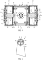
- the first fastening element 55 is shown in plan view in axial direction A.
- the projection 57 is designed in its lower area as a part-circle and is thus complementary to the design of the receptacle 63 as a circular segment.
- the projection can also Fig. 8 illustrated contact surface 69, which comes into contact with a contact surface 70 of the second fastening element 61 and thus acts as a stop to prevent relative rotation between the projection 57 and the receptacle 63.
- the contact surfaces 69, 70 extend tangentially or at an angle to the circumferential direction of the circular segment.
- the projection 56, 57 runs in the outer area on the inner assembly in the form of the upper support arm 4.
- the projection 56, 57 is provided axially on the inside of the axially outer arranged first fastening element 54, 55.
- the shafts 64, 65 are each designed as a solid shaft and separately, although alternatively a through shaft can also be provided.
- the fastening of the assemblies 3 and 4 takes place after their fastening elements 54, 55, 60, 61 have been pushed together, via an external screw connection.
- the bearing can then be preloaded using the preload bushing 68. This also enables the assemblies to be aligned with one another.
- Positioning is achieved via the seat of the pivot bearings 66, 67 in the fastening element 54, 55.
- the receptacle 62, 63 is a guide which is designed in some areas as a circular segment, so that during assembly, in addition to the frictional connection caused by the fastening with the screws, a positive connection is also created which aligns the assemblies exactly with one another.
- the fastening screws are screwed in particular from the outside through the first fastening elements 54, 55 into the second fastening elements 60, 61 in the axial direction A.
- the projection 56, 57 is designed as a combination of a pitch circle with linear contact surfaces 69.
- the positive engagement of the pitch circle ensures the exact positioning of the axis, and the contact surfaces 69 provide anti-rotation protection.
- the fastening of two assemblies shown can also be used on joints other than the second joint 8 of robot 1 or on other robots.
- the corresponding fastening can also be used on the first joint 7 of robot 1 between the base assembly 2 and the swivel arm assembly 3, on the third joint 9 between the upper support arm 4 and the lower support arm 5, or on the fourth joint 10 of robot 1 between the lower support arm 5 and the articulated arm 6.
- the receptacle and the projection can take on any complementary shape that can be aligned by means of a positive fit.
- the tapered and semicircular shapes were already shown as examples.
- dovetail guides or similar designs can also be used.
- the positive fit and/or frictional fit between the projection and the receptacle can only be adjusted during assembly by mechanically spreading or clamping the receptacle or projection.
- the fastening elements can be secured by screwing, as in the previous embodiments. However, it is also possible to use no screwing and to fix the projection in the receptacle only by clamping force. For this purpose, the projection can be pressed into the receptacle. Alternatively, a permanent connection can be provided by gluing. However, in contrast to the embodiments with a detachable fastening of the fastening elements, this does not allow for easy disassembly.
- the fastening element which is connected to the shaft of the bearing, is advantageously rigidly connected to the shaft.
- a fastening element in the form of a projection was firmly connected to the shaft.
- a fastening element in the form of a receptacle can also be firmly connected to the shaft.
- the shaft and the fastening element can be designed as separate components fastened to one another, as in the previous embodiments, or they can consist of an integral component.
- the bearing can be preloaded within the assembly. Alternatively, preloading can be applied only after the fastening elements have been secured, as shown in the previous embodiments.
- Suitable bearing types can be used for all pivot bearings, for example, any type of rolling bearing and/or plain bearing.
- the bearing is only statically determined after the first and second fastening elements have been secured. Before this, the bearing can also be indeterminate.
- the bearing is provided in axially outer jaws 22, 23 of the first assembly 5, wherein the first fastening element 26, 27 is designed as a projection 28, 29, and the second fastening element 30, 31 as a receptacle 32, 33 on both axially outer sides of the inner second assembly.
- the bearing is provided in the first assembly 4, which is arranged axially within two jaws 58, 59 of a second assembly 3.
- the first fastening elements 54, 55 are designed as projections 56, 57 which are rotatable relative to the first assembly 4 and which are received in the receptacles 62, 63 in the jaws 58, 59 of the second assembly 3. According to Fig. 7
- the first fastening element 54, 55 is rotatably mounted relative to the shaft 64, 65.
- the shaft 64, 65 can also be rotatably mounted relative to the first assembly 4, and the first fastening element 54, 55 can be fixedly arranged on the shaft 64, 65. This is particularly advantageous in designs with a continuous shaft instead of the two individual shafts 64, 65.
- the receptacle can be rotatably mounted as the first fastening element, either on axial outer sides of the first assembly or on two axial inner sides within jaws that can be formed by the first assembly.
- two robot assemblies can be designed with a system of receptacles, for example guides, and projections, for example rails.
- the receptacle is a component of one assembly and the projection is a component of the other assembly.
- two projections are provided on one assembly and two receptacles on the other assembly, which are each inserted into one another.
- one of the assemblies is provided partially within the other assembly.
- the projections can be provided either on the inside of the outer assembly or on the outside of the inner assembly, and the guides can each be provided alternatively on the outside of the inner assembly or on the inside of the outer assembly.
- Either the projections or the receptacles can be rotatable relative to their respective assembly.
- the axle bearing can be statically determined before the two assemblies are brought together, or it can still be statically indeterminate and only be statically determined when the two assemblies are assembled.
Landscapes
- Engineering & Computer Science (AREA)
- Robotics (AREA)
- Mechanical Engineering (AREA)
- Manipulator (AREA)
- Automatic Assembly (AREA)
Claims (12)
- Robot (1), comprenantun premier module (4, 5), etun second module (3, 6),dans lequel le premier module (4, 5) est un premier bras de robot et le second module (3, 6) est un second bras de robot, dans lequel le second bras de robot est relié de manière pivotante au premier bras de robot autour d'un axe de pivotement s'étendant dans une direction axiale (A),dans lequel des paliers (24, 25, 52, 53) sont prévus dans le premier bras de robot (4, 5), par l'intermédiaire desquels le second bras de robot (3, 6) peut être déplacé par rapport au premier bras de robot (4, 5),dans lequel les paliers (24, 25, 52, 53) comprennent un premier élément de fixation (26, 27, 54, 55) et des arbres montés rotatifs (34, 35, 64, 65), etle second bras de robot (3, 6) comprend un second élément de fixation (30, 31, 60, 61),dans lequel le premier élément de fixation (26, 27, 54, 55) et le second élément de fixation (30, 31, 60, 61) sont reliés l'un à l'autre, et dans lequel le premier élément de fixation (26, 27, 54, 55) et le second élément de fixation (30, 31, 60, 61) sont conçus de manière au moins partiellement complémentaire,dans lequel le premier élément de fixation (26, 27, 54, 55) ou le second élément de fixation (30, 31, 60, 61) forme un logement (32, 33, 62, 63), et l'autre du premier élément de fixation (26, 27, 54, 55) et du second élément de fixation (30, 31, 60, 61) forme une saillie (28, 29, 56, 57), et dans lequel la saillie (28, 29, 56, 57) peut être insérée dans une direction d'insertion (E) dans le logement (32, 33, 62, 63) en vue de sa fixation,dans lequel le premier bras de robot (5) est réalisé, au niveau d'une extrémité, avec deux mâchoires (22, 23) s'étendant parallèlement et à une certaine distance l'une de l'autre, dans lequel le second bras de robot (6) est monté entre lesdites mâchoires (22, 23), et des arbres (34, 35) montés rotatifs sont fournis de manière coaxiale dans les deux mâchoires (22, 23), oudans lequel le second bras de robot (3) est réalisé, au niveau d' une extrémité, avec deux mâchoires (58, 59) s'étendant parallèlement et à une certaine distance l'une de l'autre, dans lequel le premier bras de robot (4) est monté entre lesdites mâchoires (58, 59), et les extrémités d'au moins un des arbres (64, 65) agencés dans le premier bras de robot (4) sont fournies de manière coaxiale au niveau des deux côtés extérieurs du premier bras de robot (4),caractérisé en ce quela saillie (28, 29, 56, 57) est réalisée au moins partiellement de forme conique et le logement (32, 33, 62, 63) est au moins partiellement en forme de segment de cercle.
- Robot selon la revendication 1, dans lequel la saillie (28, 29, 56, 57) est au moins semi-circulaire.
- Robot selon la revendication 1 ou 2, dans lequel la saillie (28, 29, 56, 57) est conçue sous la forme d'une combinaison d'un cercle partiel avec des surfaces d'appui linéaires (69), dans lequel la saillie (28, 29, 56, 57) est conçue de préférence de manière à ce que le cercle partiel assure un positionnement exact de l'axe et que les surfaces d'appui (69) assurent une sécurité de rotation.
- Robot selon l'une quelconque des revendications précédentes, dans lequel un élément de précontrainte (41) est fourni, avec lequel une précontrainte peut être appliquée sur la saillie (28, 29, 56, 57) dans la direction d'insertion (E).
- Robot selon l'une quelconque des revendications précédentes, dans lequel le logement (32, 33) est un guide et la saillie (28, 29) est un rail.
- Robot selon l'une quelconque des revendications précédentes, dans lequel la saillie (28, 29) est conçue de manière conique dans la direction d'insertion (E).
- Robot selon l'une quelconque des revendications précédentes, dans lequel les éléments de fixation peuvent être insérés l'un dans l'autre de manière essentiellement orthogonale par rapport à la direction axiale (A).
- Robot selon l'une quelconque des revendications précédentes, dans lequel les arbres (34, 35, 64, 65) sont montés pouvant tourner autour de l'axe de pivotement dans le premier bras de robot (4, 5), et dans lequel le premier élément de fixation (26, 27, 54, 55) est fixé sur les arbres (34, 35, 64, 65) ou est conçu pour faire partie intégrante des arbres (34, 35, 64, 65).
- Robot selon l'une quelconque des revendications précédentes, dans lequel au moins un arbre (34, 35, 64, 65) est mis en œuvre sous la forme d'un arbre creux, et au moins un câble et/ou au moins une vis de fixation (46, 47) sont guidés à travers l'intérieur de l'arbre creux.
- Procédé de montage de deux modules (2, 3, 4) comprenant deux bras de robot d'un robot (1), comprenant les étapes consistant à :fournir un premier bras de robot (4) comprenant une saillie (56, 57) dans laquelle les extrémités d'au moins un des arbres (64, 65) agencés dans le premier bras de robot (4) sont fournies de manière coaxiale au niveau des deux côtés extérieurs,fournir un second bras de robot (3) qui est réalisé, au niveau d'une extrémité, avec deux mâchoires (58, 59) s'étendant parallèlement et à une certaine distance l'une de l'autre et comprenant un logement (62, 63),dans lequel la saillie (56, 57), par rapport au premier bras de robot (4), ou le logement (32, 33), par rapport au second bras de robot (3), peut être tourné(e) autour d'un axe de pivotement,monter le premier bras de robot (4) entre les mâchoires (58, 59) du second bras de robot (3),insérer la saillie (56, 57) dans le logement (62, 63) dans une direction d'insertion linéaire (E), dans lequel la saillie (56, 57) est conçue au moins partiellement de forme conique et le logement (62, 63) est au moins partiellement en forme de segment de cercle, etfixer la saillie (56, 57) dans le logement (62, 63).
- Procédé de montage de deux modules (5, 6), comprenant deux bras de robot (5, 6) d'un robot (1), comprenant les étapes consistant à :fournir un premier bras de robot (5) qui est réalisé, au niveau d'une extrémité, avec deux mâchoires (22, 23) s'étendant parallèlement et à distance l'une de l'autre etcomprenant une saillie (28, 29) dans laquelle des arbres montés rotatifs (34, 35) sont fournis de manière coaxiale,fournir un second bras de robot (6) avec un logement (32, 33),dans lequel la saillie (28, 29), par rapport au premier bras de robot (5), ou le logement (32, 33), par rapport au second bras de robot (6), peut être tourné(e) autour d'un axe de pivotement,monter le second bras de robot (6) entre les mâchoires (22, 23) du premier bras de robot (5),insérer la saillie (28, 29) dans le logement (32, 33) dans une direction d'insertion linéaire (E), dans lequel la saillie (28, 29) est conçue au moins partiellement de forme conique et le logement (32, 33) est au moins partiellement en forme de segment de cercle, etfixer la saillie (28, 29) dans le logement (32, 33).
- Procédé selon la revendication 10 ou 11, dans lequel l'étape de fixation de la saillie (28, 29, 56, 57) dans le logement (32, 33, 62, 63) comprend une étape consistant à la précontraindre dans la direction d'insertion (E).
Applications Claiming Priority (3)
| Application Number | Priority Date | Filing Date | Title |
|---|---|---|---|
| EP18196270.5A EP3626406A1 (fr) | 2018-09-24 | 2018-09-24 | Robot pourvu d'éléments de fixation complémentaires permettant de raccorder les modules |
| EP19762414.1A EP3856464B1 (fr) | 2018-09-24 | 2019-09-06 | Robot pourvu d'éléments de fixation complémentaires permettant de raccorder les modules |
| PCT/EP2019/073810 WO2020064302A1 (fr) | 2018-09-24 | 2019-09-06 | Robot doté d'éléments de fixation complémentaires pour la liaison de modules |
Related Parent Applications (2)
| Application Number | Title | Priority Date | Filing Date |
|---|---|---|---|
| EP19762414.1A Division EP3856464B1 (fr) | 2018-09-24 | 2019-09-06 | Robot pourvu d'éléments de fixation complémentaires permettant de raccorder les modules |
| EP19762414.1A Division-Into EP3856464B1 (fr) | 2018-09-24 | 2019-09-06 | Robot pourvu d'éléments de fixation complémentaires permettant de raccorder les modules |
Publications (2)
| Publication Number | Publication Date |
|---|---|
| EP4104977A1 EP4104977A1 (fr) | 2022-12-21 |
| EP4104977B1 true EP4104977B1 (fr) | 2025-04-23 |
Family
ID=63708090
Family Applications (3)
| Application Number | Title | Priority Date | Filing Date |
|---|---|---|---|
| EP18196270.5A Withdrawn EP3626406A1 (fr) | 2018-09-24 | 2018-09-24 | Robot pourvu d'éléments de fixation complémentaires permettant de raccorder les modules |
| EP22187367.2A Active EP4104977B1 (fr) | 2018-09-24 | 2019-09-06 | Robot avec fixations de connexion d'assemblage complémentaire |
| EP19762414.1A Active EP3856464B1 (fr) | 2018-09-24 | 2019-09-06 | Robot pourvu d'éléments de fixation complémentaires permettant de raccorder les modules |
Family Applications Before (1)
| Application Number | Title | Priority Date | Filing Date |
|---|---|---|---|
| EP18196270.5A Withdrawn EP3626406A1 (fr) | 2018-09-24 | 2018-09-24 | Robot pourvu d'éléments de fixation complémentaires permettant de raccorder les modules |
Family Applications After (1)
| Application Number | Title | Priority Date | Filing Date |
|---|---|---|---|
| EP19762414.1A Active EP3856464B1 (fr) | 2018-09-24 | 2019-09-06 | Robot pourvu d'éléments de fixation complémentaires permettant de raccorder les modules |
Country Status (6)
| Country | Link |
|---|---|
| US (1) | US11518047B2 (fr) |
| EP (3) | EP3626406A1 (fr) |
| JP (1) | JP7281538B2 (fr) |
| KR (1) | KR102480328B1 (fr) |
| CN (1) | CN112805125A (fr) |
| WO (1) | WO2020064302A1 (fr) |
Families Citing this family (3)
| Publication number | Priority date | Publication date | Assignee | Title |
|---|---|---|---|---|
| CN109895109B (zh) * | 2019-03-01 | 2021-03-16 | 达闼科技(北京)有限公司 | 一种机器人腰部骨架及机器人 |
| DE102020214332A1 (de) | 2020-11-13 | 2022-05-19 | Kuka Deutschland Gmbh | Roboterarm und Verfahren zum Montieren eines Roboterarms |
| DE102021108201B3 (de) * | 2021-03-31 | 2022-07-07 | Fft Produktionssysteme Gmbh & Co. Kg | System und Verfahren zur Abarbeitung einer Montageaufgabe mittels eines Roboters |
Family Cites Families (18)
| Publication number | Priority date | Publication date | Assignee | Title |
|---|---|---|---|---|
| JPS646229Y2 (fr) * | 1985-07-11 | 1989-02-16 | ||
| JPS6292179U (fr) * | 1986-11-14 | 1987-06-12 | ||
| US4949586A (en) * | 1988-11-07 | 1990-08-21 | Intelmatic Corp. | Actuator swing arm mechanism |
| US5540541A (en) * | 1990-11-28 | 1996-07-30 | Robert Bosch Gmbh | Pivotal robot arm |
| JPH10166286A (ja) * | 1996-12-06 | 1998-06-23 | Sony Corp | ロボツト装置、接続装置及びアクチユエータモジユール |
| SE524549C2 (sv) * | 2002-07-09 | 2004-08-24 | Abb Ab | Anordning vid en industrirobot |
| US8175747B2 (en) * | 2003-12-22 | 2012-05-08 | Irobou Co., Ltd. | Joinable robot component for robot toy, modifiable robot toy using the joinable robot components, and control method thereof |
| JP5293263B2 (ja) * | 2009-02-25 | 2013-09-18 | 日本精工株式会社 | マニピュレータの関節部用軸受ユニットおよびマニピュレータの関節部 |
| KR101200461B1 (ko) * | 2010-06-04 | 2012-11-12 | (주)로보티즈 | 2자유도를 갖는 액츄에이터 모듈 및 이를 이용한 로봇 관절 구조 |
| JP2012096298A (ja) * | 2010-10-29 | 2012-05-24 | Nsk Ltd | マニピュレータ用関節部 |
| JP5576911B2 (ja) * | 2012-08-20 | 2014-08-20 | ファナック株式会社 | 両持ち式のアーム部材を備えた多関節ロボット |
| JP2013056419A (ja) * | 2012-12-25 | 2013-03-28 | Precision Machinery Research Development Center | サーボ装置 |
| CN103264389B (zh) * | 2013-05-14 | 2015-09-16 | 东南大学 | 一种可全向运动的模块化自重构机器人的单元模块结构 |
| JP6438937B2 (ja) * | 2014-03-25 | 2018-12-19 | 株式会社Fuji | 多関節ロボットアーム |
| CN105437227B (zh) * | 2015-12-28 | 2017-10-24 | 苏州大学 | 平面关节型机器人及其控制系统 |
| CN205835408U (zh) * | 2016-05-27 | 2016-12-28 | 深圳市优必选科技有限公司 | 机器人关节结构 |
| CN207237267U (zh) * | 2017-08-11 | 2018-04-17 | 李盛 | 一种智能玩具机器人 |
| CN207710822U (zh) | 2017-11-21 | 2018-08-10 | 深圳市女娲机器人科技有限公司 | 一种人形机器人手臂及人形机器人 |
-
2018
- 2018-09-24 EP EP18196270.5A patent/EP3626406A1/fr not_active Withdrawn
-
2019
- 2019-09-06 CN CN201980062567.2A patent/CN112805125A/zh active Pending
- 2019-09-06 JP JP2021516799A patent/JP7281538B2/ja active Active
- 2019-09-06 US US17/278,521 patent/US11518047B2/en active Active
- 2019-09-06 KR KR1020217011235A patent/KR102480328B1/ko active Active
- 2019-09-06 EP EP22187367.2A patent/EP4104977B1/fr active Active
- 2019-09-06 EP EP19762414.1A patent/EP3856464B1/fr active Active
- 2019-09-06 WO PCT/EP2019/073810 patent/WO2020064302A1/fr not_active Ceased
Also Published As
| Publication number | Publication date |
|---|---|
| CN112805125A (zh) | 2021-05-14 |
| KR102480328B1 (ko) | 2022-12-23 |
| US20210308877A1 (en) | 2021-10-07 |
| KR20210064271A (ko) | 2021-06-02 |
| EP4104977A1 (fr) | 2022-12-21 |
| EP3626406A1 (fr) | 2020-03-25 |
| JP7281538B2 (ja) | 2023-05-25 |
| EP3856464B1 (fr) | 2022-11-02 |
| JP2022502270A (ja) | 2022-01-11 |
| WO2020064302A1 (fr) | 2020-04-02 |
| US11518047B2 (en) | 2022-12-06 |
| EP3856464A1 (fr) | 2021-08-04 |
Similar Documents
| Publication | Publication Date | Title |
|---|---|---|
| EP3846974B1 (fr) | Stockage conjoint pour un robot pourvu d'élément de précontrainte élastiquement compressible | |
| EP1998930B1 (fr) | Dispositif de positionnement | |
| EP2241416B1 (fr) | Robot doté d'une cinématique delta | |
| EP3612432B1 (fr) | Entraînement de réglage pour une colonne de direction, unité d'entraînement pour un entraînement de réglage, colonne de direction à réglage motorisé pour un véhicule automobile et procédé de fabrication d'un entraînement de réglage pour une colonne de direction | |
| DE102016211694B3 (de) | Getriebeeinheit für ein Kraftfahrzeug | |
| DE102016004787A1 (de) | Antriebsvorrichtung für einen Roboter und Verfahren zu ihrer Herstellung | |
| DE102015012960A1 (de) | Robotersystem und Gehäuseteil für ein solches Robotersystem | |
| EP2855237A1 (fr) | Colonne de direction pour un véhicule automobile | |
| DE10250994A1 (de) | Spindel- oder Schneckenantrieb für Verstelleinrichtungen in Kraftfahrzeugen | |
| EP3856464B1 (fr) | Robot pourvu d'éléments de fixation complémentaires permettant de raccorder les modules | |
| DE102012108031A1 (de) | Halter für eine Fügevorrichtung | |
| EP3815937B1 (fr) | Crochet d'attelage | |
| DE102004033741B3 (de) | Lenkadapter für Kraftfahrzeuge | |
| EP0962280A2 (fr) | Dispositif d'alignement | |
| EP3724056B1 (fr) | Colonne de direction à réglage électrique conçue pour un véhicule automobile | |
| DE102018118615B4 (de) | Relativführungsvorrichtung für eine radträgerseitig angeordnete Lenkanordnung | |
| DE202016103794U1 (de) | Getriebeeinheit für ein Kraftfahrzeug | |
| EP4051528B1 (fr) | Agencement d'engrenage destiné à un agencement d'entraînement de broche, agencement d'entraînement de broche et siège de véhicule | |
| EP3765244B1 (fr) | Articulation avec profilé multifonctionnel pour manipulateur | |
| EP4144615B1 (fr) | Actionneur, colonne de direction pour un véhicule automobile, ainsi que procédé de fabrication et/ou de montage d'un actionneur | |
| DE102017217629B4 (de) | Aktuator einer Lenkung, insbesondere für eine Hinterachslenkung eines Kraftfahrzeuges | |
| DE102016006371B4 (de) | Vorrichtung zum Ausrichten und Verbinden einer Haube mit einem Gehäuse | |
| AT504095B1 (de) | Halteeinrichtung | |
| DE102016211695A1 (de) | Getriebeeinheit für ein Kraftfahrzeug | |
| DE102017116254A1 (de) | Lenkaktuator |
Legal Events
| Date | Code | Title | Description |
|---|---|---|---|
| PUAI | Public reference made under article 153(3) epc to a published international application that has entered the european phase |
Free format text: ORIGINAL CODE: 0009012 |
|
| STAA | Information on the status of an ep patent application or granted ep patent |
Free format text: STATUS: THE APPLICATION HAS BEEN PUBLISHED |
|
| AC | Divisional application: reference to earlier application |
Ref document number: 3856464 Country of ref document: EP Kind code of ref document: P |
|
| AK | Designated contracting states |
Kind code of ref document: A1 Designated state(s): AL AT BE BG CH CY CZ DE DK EE ES FI FR GB GR HR HU IE IS IT LI LT LU LV MC MK MT NL NO PL PT RO RS SE SI SK SM TR |
|
| P01 | Opt-out of the competence of the unified patent court (upc) registered |
Effective date: 20230515 |
|
| STAA | Information on the status of an ep patent application or granted ep patent |
Free format text: STATUS: REQUEST FOR EXAMINATION WAS MADE |
|
| 17P | Request for examination filed |
Effective date: 20230621 |
|
| RBV | Designated contracting states (corrected) |
Designated state(s): AL AT BE BG CH CY CZ DE DK EE ES FI FR GB GR HR HU IE IS IT LI LT LU LV MC MK MT NL NO PL PT RO RS SE SI SK SM TR |
|
| GRAP | Despatch of communication of intention to grant a patent |
Free format text: ORIGINAL CODE: EPIDOSNIGR1 |
|
| STAA | Information on the status of an ep patent application or granted ep patent |
Free format text: STATUS: GRANT OF PATENT IS INTENDED |
|
| RIC1 | Information provided on ipc code assigned before grant |
Ipc: B25J 19/00 20060101ALI20241022BHEP Ipc: B25J 9/08 20060101ALI20241022BHEP Ipc: B25J 9/04 20060101ALI20241022BHEP Ipc: B25J 9/00 20060101AFI20241022BHEP |
|
| INTG | Intention to grant announced |
Effective date: 20241115 |
|
| GRAS | Grant fee paid |
Free format text: ORIGINAL CODE: EPIDOSNIGR3 |
|
| GRAA | (expected) grant |
Free format text: ORIGINAL CODE: 0009210 |
|
| STAA | Information on the status of an ep patent application or granted ep patent |
Free format text: STATUS: THE PATENT HAS BEEN GRANTED |
|
| AC | Divisional application: reference to earlier application |
Ref document number: 3856464 Country of ref document: EP Kind code of ref document: P |
|
| AK | Designated contracting states |
Kind code of ref document: B1 Designated state(s): AL AT BE BG CH CY CZ DE DK EE ES FI FR GB GR HR HU IE IS IT LI LT LU LV MC MK MT NL NO PL PT RO RS SE SI SK SM TR |
|
| REG | Reference to a national code |
Ref country code: GB Ref legal event code: FG4D Free format text: NOT ENGLISH |
|
| REG | Reference to a national code |
Ref country code: CH Ref legal event code: EP |
|
| REG | Reference to a national code |
Ref country code: DE Ref legal event code: R096 Ref document number: 502019013268 Country of ref document: DE |
|
| REG | Reference to a national code |
Ref country code: IE Ref legal event code: FG4D Free format text: LANGUAGE OF EP DOCUMENT: GERMAN |
|
| REG | Reference to a national code |
Ref country code: NL Ref legal event code: MP Effective date: 20250423 |
|
| PG25 | Lapsed in a contracting state [announced via postgrant information from national office to epo] |
Ref country code: NL Free format text: LAPSE BECAUSE OF FAILURE TO SUBMIT A TRANSLATION OF THE DESCRIPTION OR TO PAY THE FEE WITHIN THE PRESCRIBED TIME-LIMIT Effective date: 20250423 |
|
| PG25 | Lapsed in a contracting state [announced via postgrant information from national office to epo] |
Ref country code: PT Free format text: LAPSE BECAUSE OF FAILURE TO SUBMIT A TRANSLATION OF THE DESCRIPTION OR TO PAY THE FEE WITHIN THE PRESCRIBED TIME-LIMIT Effective date: 20250825 Ref country code: ES Free format text: LAPSE BECAUSE OF FAILURE TO SUBMIT A TRANSLATION OF THE DESCRIPTION OR TO PAY THE FEE WITHIN THE PRESCRIBED TIME-LIMIT Effective date: 20250423 Ref country code: FI Free format text: LAPSE BECAUSE OF FAILURE TO SUBMIT A TRANSLATION OF THE DESCRIPTION OR TO PAY THE FEE WITHIN THE PRESCRIBED TIME-LIMIT Effective date: 20250423 |
|
| PGFP | Annual fee paid to national office [announced via postgrant information from national office to epo] |
Ref country code: DE Payment date: 20250923 Year of fee payment: 7 |
|
| REG | Reference to a national code |
Ref country code: LT Ref legal event code: MG9D |
|
| PG25 | Lapsed in a contracting state [announced via postgrant information from national office to epo] |
Ref country code: GR Free format text: LAPSE BECAUSE OF FAILURE TO SUBMIT A TRANSLATION OF THE DESCRIPTION OR TO PAY THE FEE WITHIN THE PRESCRIBED TIME-LIMIT Effective date: 20250724 Ref country code: NO Free format text: LAPSE BECAUSE OF FAILURE TO SUBMIT A TRANSLATION OF THE DESCRIPTION OR TO PAY THE FEE WITHIN THE PRESCRIBED TIME-LIMIT Effective date: 20250723 |
|
| PG25 | Lapsed in a contracting state [announced via postgrant information from national office to epo] |
Ref country code: PL Free format text: LAPSE BECAUSE OF FAILURE TO SUBMIT A TRANSLATION OF THE DESCRIPTION OR TO PAY THE FEE WITHIN THE PRESCRIBED TIME-LIMIT Effective date: 20250423 |
|
| PG25 | Lapsed in a contracting state [announced via postgrant information from national office to epo] |
Ref country code: BG Free format text: LAPSE BECAUSE OF FAILURE TO SUBMIT A TRANSLATION OF THE DESCRIPTION OR TO PAY THE FEE WITHIN THE PRESCRIBED TIME-LIMIT Effective date: 20250423 |
|
| PG25 | Lapsed in a contracting state [announced via postgrant information from national office to epo] |
Ref country code: HR Free format text: LAPSE BECAUSE OF FAILURE TO SUBMIT A TRANSLATION OF THE DESCRIPTION OR TO PAY THE FEE WITHIN THE PRESCRIBED TIME-LIMIT Effective date: 20250423 |
|
| PG25 | Lapsed in a contracting state [announced via postgrant information from national office to epo] |
Ref country code: RS Free format text: LAPSE BECAUSE OF FAILURE TO SUBMIT A TRANSLATION OF THE DESCRIPTION OR TO PAY THE FEE WITHIN THE PRESCRIBED TIME-LIMIT Effective date: 20250723 |
|
| PG25 | Lapsed in a contracting state [announced via postgrant information from national office to epo] |
Ref country code: IS Free format text: LAPSE BECAUSE OF FAILURE TO SUBMIT A TRANSLATION OF THE DESCRIPTION OR TO PAY THE FEE WITHIN THE PRESCRIBED TIME-LIMIT Effective date: 20250823 |
|
| PG25 | Lapsed in a contracting state [announced via postgrant information from national office to epo] |
Ref country code: LV Free format text: LAPSE BECAUSE OF FAILURE TO SUBMIT A TRANSLATION OF THE DESCRIPTION OR TO PAY THE FEE WITHIN THE PRESCRIBED TIME-LIMIT Effective date: 20250423 |
|
| PG25 | Lapsed in a contracting state [announced via postgrant information from national office to epo] |
Ref country code: DK Free format text: LAPSE BECAUSE OF FAILURE TO SUBMIT A TRANSLATION OF THE DESCRIPTION OR TO PAY THE FEE WITHIN THE PRESCRIBED TIME-LIMIT Effective date: 20250423 Ref country code: SM Free format text: LAPSE BECAUSE OF FAILURE TO SUBMIT A TRANSLATION OF THE DESCRIPTION OR TO PAY THE FEE WITHIN THE PRESCRIBED TIME-LIMIT Effective date: 20250423 |
|
| PG25 | Lapsed in a contracting state [announced via postgrant information from national office to epo] |
Ref country code: CZ Free format text: LAPSE BECAUSE OF FAILURE TO SUBMIT A TRANSLATION OF THE DESCRIPTION OR TO PAY THE FEE WITHIN THE PRESCRIBED TIME-LIMIT Effective date: 20250423 |
|
| PG25 | Lapsed in a contracting state [announced via postgrant information from national office to epo] |
Ref country code: EE Free format text: LAPSE BECAUSE OF FAILURE TO SUBMIT A TRANSLATION OF THE DESCRIPTION OR TO PAY THE FEE WITHIN THE PRESCRIBED TIME-LIMIT Effective date: 20250423 |
|
| REG | Reference to a national code |
Ref country code: DE Ref legal event code: R097 Ref document number: 502019013268 Country of ref document: DE |
|
| PG25 | Lapsed in a contracting state [announced via postgrant information from national office to epo] |
Ref country code: SK Free format text: LAPSE BECAUSE OF FAILURE TO SUBMIT A TRANSLATION OF THE DESCRIPTION OR TO PAY THE FEE WITHIN THE PRESCRIBED TIME-LIMIT Effective date: 20250423 |
|
| PG25 | Lapsed in a contracting state [announced via postgrant information from national office to epo] |
Ref country code: IT Free format text: LAPSE BECAUSE OF FAILURE TO SUBMIT A TRANSLATION OF THE DESCRIPTION OR TO PAY THE FEE WITHIN THE PRESCRIBED TIME-LIMIT Effective date: 20250423 |
|
| PG25 | Lapsed in a contracting state [announced via postgrant information from national office to epo] |
Ref country code: RO Free format text: LAPSE BECAUSE OF FAILURE TO SUBMIT A TRANSLATION OF THE DESCRIPTION OR TO PAY THE FEE WITHIN THE PRESCRIBED TIME-LIMIT Effective date: 20250423 |
|
| PLBE | No opposition filed within time limit |
Free format text: ORIGINAL CODE: 0009261 |
|
| STAA | Information on the status of an ep patent application or granted ep patent |
Free format text: STATUS: NO OPPOSITION FILED WITHIN TIME LIMIT |
|
| REG | Reference to a national code |
Ref country code: CH Ref legal event code: L10 Free format text: ST27 STATUS EVENT CODE: U-0-0-L10-L00 (AS PROVIDED BY THE NATIONAL OFFICE) Effective date: 20260304 |
|
| 26N | No opposition filed |
Effective date: 20260126 |
|
| REG | Reference to a national code |
Ref country code: CH Ref legal event code: H13 Free format text: ST27 STATUS EVENT CODE: U-0-0-H10-H13 (AS PROVIDED BY THE NATIONAL OFFICE) Effective date: 20260425 |