EP4105123B1 - Umwandelbares schwebefähiges fluggerät und zugehöriges steuerungsverfahren - Google Patents
Umwandelbares schwebefähiges fluggerät und zugehöriges steuerungsverfahren Download PDFInfo
- Publication number
- EP4105123B1 EP4105123B1 EP21180396.0A EP21180396A EP4105123B1 EP 4105123 B1 EP4105123 B1 EP 4105123B1 EP 21180396 A EP21180396 A EP 21180396A EP 4105123 B1 EP4105123 B1 EP 4105123B1
- Authority
- EP
- European Patent Office
- Prior art keywords
- aircraft
- axis
- configuration
- rotors
- airframe
- Prior art date
- Legal status (The legal status is an assumption and is not a legal conclusion. Google has not performed a legal analysis and makes no representation as to the accuracy of the status listed.)
- Active
Links
Images


Classifications
-
- B—PERFORMING OPERATIONS; TRANSPORTING
- B64—AIRCRAFT; AVIATION; COSMONAUTICS
- B64C—AEROPLANES; HELICOPTERS
- B64C29/00—Aircraft capable of landing or taking-off vertically, e.g. vertical take-off and landing [VTOL] aircraft
- B64C29/0008—Aircraft capable of landing or taking-off vertically, e.g. vertical take-off and landing [VTOL] aircraft having its flight directional axis horizontal when grounded
- B64C29/0016—Aircraft capable of landing or taking-off vertically, e.g. vertical take-off and landing [VTOL] aircraft having its flight directional axis horizontal when grounded the lift during taking-off being created by free or ducted propellers or by blowers
- B64C29/0025—Aircraft capable of landing or taking-off vertically, e.g. vertical take-off and landing [VTOL] aircraft having its flight directional axis horizontal when grounded the lift during taking-off being created by free or ducted propellers or by blowers the propellers being fixed relative to the fuselage
-
- B—PERFORMING OPERATIONS; TRANSPORTING
- B64—AIRCRAFT; AVIATION; COSMONAUTICS
- B64C—AEROPLANES; HELICOPTERS
- B64C27/00—Rotorcraft; Rotors peculiar thereto
- B64C27/22—Compound rotorcraft, i.e. aircraft using in flight the features of both aeroplane and rotorcraft
- B64C27/28—Compound rotorcraft, i.e. aircraft using in flight the features of both aeroplane and rotorcraft with forward-propulsion propellers pivotable to act as lifting rotors
-
- B—PERFORMING OPERATIONS; TRANSPORTING
- B64—AIRCRAFT; AVIATION; COSMONAUTICS
- B64C—AEROPLANES; HELICOPTERS
- B64C29/00—Aircraft capable of landing or taking-off vertically, e.g. vertical take-off and landing [VTOL] aircraft
- B64C29/0008—Aircraft capable of landing or taking-off vertically, e.g. vertical take-off and landing [VTOL] aircraft having its flight directional axis horizontal when grounded
- B64C29/0016—Aircraft capable of landing or taking-off vertically, e.g. vertical take-off and landing [VTOL] aircraft having its flight directional axis horizontal when grounded the lift during taking-off being created by free or ducted propellers or by blowers
- B64C29/0033—Aircraft capable of landing or taking-off vertically, e.g. vertical take-off and landing [VTOL] aircraft having its flight directional axis horizontal when grounded the lift during taking-off being created by free or ducted propellers or by blowers the propellers being tiltable relative to the fuselage
-
- B—PERFORMING OPERATIONS; TRANSPORTING
- B64—AIRCRAFT; AVIATION; COSMONAUTICS
- B64C—AEROPLANES; HELICOPTERS
- B64C39/00—Aircraft not otherwise provided for
- B64C39/08—Aircraft not otherwise provided for having multiple wings
-
- B—PERFORMING OPERATIONS; TRANSPORTING
- B64—AIRCRAFT; AVIATION; COSMONAUTICS
- B64C—AEROPLANES; HELICOPTERS
- B64C39/00—Aircraft not otherwise provided for
- B64C39/12—Canard-type aircraft
-
- B—PERFORMING OPERATIONS; TRANSPORTING
- B64—AIRCRAFT; AVIATION; COSMONAUTICS
- B64C—AEROPLANES; HELICOPTERS
- B64C5/00—Stabilising surfaces
- B64C5/02—Tailplanes
-
- B—PERFORMING OPERATIONS; TRANSPORTING
- B64—AIRCRAFT; AVIATION; COSMONAUTICS
- B64C—AEROPLANES; HELICOPTERS
- B64C5/00—Stabilising surfaces
- B64C5/06—Fins
Definitions
- the present invention relates to a convertible aircraft, i.e., an aircraft that is switchable between a first configuration of hovering flight or flight along a predominantly vertical trajectory and a second forward flight or cruise configuration.
- aeroplanes are normally used for high cruising speeds, in particular greater than 150 knots (278 km/h) and high altitudes, e.g. above 30,000 feet (9144 m). At cruising speeds and high altitudes, aeroplanes use fixed wings to generate the lift necessary to sustain the plane. A sufficient value of this lift can only be obtained by accelerating the aeroplane on runways of considerable length. These runways are also necessary to allow the same aeroplanes to land.
- helicopters In contrast, helicopters normally have lower cruising speeds than aeroplanes and generate the necessary lift for sustenance through the rotation of the main rotor blades. As a result, helicopters can land/take off without the need for a horizontal speed and using particularly small surfaces. Moreover, helicopters are able to hover and to fly at relatively low altitudes and speeds, resulting thus as particularly manoeuvrable and suitable for demanding manoeuvres such as rescuing people in the mountains or at sea.
- helicopters have inherent limitations in terms of maximum operational altitude, which is around 20000 feet (6096 m), and maximum operational speed, which cannot exceed 150 knots (278 km/h).
- convertiplanes are known and which constitute a type of convertible aircraft.
- the convertiplane described in the aforesaid application essentially comprises:
- the convertiplane further comprises:
- the rotors can be inclined relative to the wing around a fourth axis, preferably parallel to the second axis.
- the convertiplanes are also able to selectively assume:
- patent application WO-A-2020/105045 describes a convertible aircraft comprising essentially:
- the aircraft described in WO-A-2020/105045 further comprises:
- first rotors and second rotors are controllable independently of each other so as to provide respective first and second thrusts that can be adjusted independently of each other.
- a pair of second rotors is arranged at free ends of respective half-wings while the other pair of second rotors is arranged at free ends of respective aerodynamic surfaces of the tail portion.
- the second rotors are inclinable between a first position wherein the respective second axes are arranged orthogonal to the longitudinal direction of the aircraft and provide a vertical thrust, and a second position wherein respective second axes are arranged parallel to the longitudinal direction of the aircraft and provide a thrust parallel to the forward direction of the aircraft.
- the position of the second rotors at the free ends of the respective half-wings causes problems of aeroelastic interaction with the half-wings themselves, thus determining a potential risk situation for the safety of the aircraft.
- Aim of the present invention is to realize a convertible aircraft which allows to satisfy at least one of the needs specified above in a simple and economical way.
- EP 3 656 669 A1 discloses a convertible aircraft according to the preamble of claim 1.
- this aim is achieved by a convertible aircraft capable of hovering as claimed in claim 1.
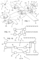
- 1 denotes an aircraft capable of hovering.
- the aircraft 1 is selectively switchable between:
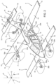
- the aircraft 1 essentially comprises:
- the aircraft 1 proceeds in a direction that is oriented from tail 5 to nose 4.
- the half-wings 3 are intended to provide a first lift value to the aircraft 1 which is adapted to sustain the aircraft 1 arranged in the second configuration.
- the half-wings 3 comprise respective free ends 15 opposite the airframe 2.
- the half-wings 3 extend superiorly to the airframe 2.
- the semi-axes 3 comprise:
- the tail portion 6 is preferably T-shaped and comprises, in turn:
- the aircraft 1 further comprises a pair of canard-type aerodynamic surfaces 9 projecting cantilevered from respective mutually opposite sides of the nose 4 of the airframe 2 and adapted to generate a third lift/downforce value to ensure the desired degree of longitudinal stability to the aircraft 1 itself arranged in the second configuration.
- the aerodynamic surfaces 9 comprise, in turn:
- root 17 and end 18 portions are coplanar with each other.
- the wingspan L1 of the half-wings 3 is greater than the wingspan L2 of the aerodynamic surfaces 8.
- the wingspan L2 of the aerodynamic surfaces 9 is greater than the wingspan L3 of the aerodynamic surfaces 8.
- the wingspan of the aerodynamic surfaces 8 ranges between 40 and 500 of the wingspan of the aerodynamic surfaces 9.
- the wingspan of the aerodynamic surfaces 9 ranges between 70 and 900 of the wingspan of the half-wings 3.
- wingsspan means the distance between opposite free ends 17, 18 of the respective half-wings 3 and aerodynamic surfaces 8, 9.
- the aerodynamic surfaces 9 are arranged inferiorly to the half-wings 3.
- the half-wings 3 are arranged inferiorly to the aerodynamic surfaces 8.
- the aerodynamic surfaces 8 comprise respective appendages 14 which are movably connected thereto to adjust the second lift value and to contribute to the control of the aircraft 1.
- the aircraft 1 also comprises:
- the axes F, G of the rotors 22a, 22b are inclinable with respect to the axis H by more or less fifteen degrees towards the nose 4 or the tail 5 with respect to the axis Z.
- the aircraft 1 further comprises a unit 71 (shown schematically in Figures 11 and 15 ) receiving at input a plurality of control signals provided by the crew, an autopilot or a remote control system, and programmed to provide as output a plurality of commands to command the rotors 20a, 20b; 21a, 21b; 22a, 22b so that they provide desired values of the relative thrusts T1, T2; T3, T4; T5, T6 ( Figures 6a-6h ).
- a unit 71 shown schematically in Figures 11 and 15 ) receiving at input a plurality of control signals provided by the crew, an autopilot or a remote control system, and programmed to provide as output a plurality of commands to command the rotors 20a, 20b; 21a, 21b; 22a, 22b so that they provide desired values of the relative thrusts T1, T2; T3, T4; T5, T6 ( Figures 6a-6h ).
- control unit 71 is programmed to command the rotors 20a, 20b; 21a, 21b; 22a, 22b to generate respective independent thrusts T1, T2; T3, T4; T5, T6.
- control unit 71 is programmed to command the rotors 20a, 20b; 21a, 21b; to generate respective thrusts T1, T2 (T3, T4) having a resultant which is parallel to the axis Z, either when the aircraft 1 is in the first configuration or when the aircraft 1 is in the second configuration.
- the control unit 71 is programmed to command the rotors 20a, 20b; 21a, 21b to generate respective zero thrusts T1, T2; T3, T4 under predetermined operating conditions and when the aircraft 1 is in the first configuration.
- the axes B, C; D, E and F, G are arranged symmetrically to the axis Y.
- the axes B, C, D and E are parallel to each other and parallel to the axis Z.
- the axes B, D, F; C, E, G are aligned with each other parallel to the axis z when the aircraft 1 is arranged in the first configuration.
- the axis H is parallel to the axis X.
- the axes F, G are arranged parallel to the axis Z when the rotors 22a, 22b are arranged in the first position.
- the axes F, G are arranged orthogonally to the axes B, C; D, E and parallel to the axis Y when the rotors 22a, 22b are arranged in the second position.
- the thrusts T1, T2; T3, T4 have a main component parallel to the respective axes B, C; D, and orthogonal to the axis Z either when the aircraft 1 is arranged in the first configuration or when the aircraft 1 is arranged in the second configuration.
- the thrusts T5, T6 have a main component which is parallel to the axes B, C; D, E and the axis Z when the aircraft 1 is arranged in the first configuration and a main component to the axis Y when the aircraft 1 is arranged in the second configuration.
- the rotors 20a, 20b; 21a, 21b; 22a, 22b are with fixed pitch.
- the rotors 20a, 20b; 21a, 21b; 22a, 22c are driven by respective electric motors.
- the aircraft 1 also comprises:
- the supports 32a, 32b are spaced apart from the ends 15 of the respective half-wings 3, with reference to an extension direction of the half-wings 3.
- the supports 32a, 32b are carried by respective root portions 11 of respective half-wings 3.
- the supports 30a, 30b are spaced apart from the ends 16 of the respective aerodynamic surfaces 9, with reference to an extension direction of the aerodynamic surfaces 9.
- the supports 30a, 30b are conformed as respective rods projecting cantilevered below from respective aerodynamic surfaces 9 anteriorly to the nose 4.
- the supports 30a, 30b are fixed to respective root portions 17 of corresponding aerodynamic surfaces 9.
- the axes B, C are arranged anteriorly to the nose 4.
- the supports 31a, 31b are conformed as rods projecting cantilevered from respective sidewalls 62 of the airframe 2 laterally to the fin 7, posteriorly to the respective half-wings 3 and anteriorly to the respective aerodynamic surfaces 8.
- the rotors 21a, 21b are arranged laterally to the fin 7 and inferiorly to the respective aerodynamic surfaces 8, and posteriorly to the respective half-wings 3.
- the axes D, E are arranged anteriorly to the respective aerodynamic surfaces 8.
- the supports 32a, 32b comprise:
- the pins 34a, 34b are interposed between the respective half-wings 3 and the nose 4 along the axis Y.
- the rotors 22a, 22b are interposed between the respective half-wings 3 and the nose 4 along the axis Y either when the aircraft 1 is arranged in the first configuration or when the aircraft 1 is arranged in the second configuration.
- the rotors 22a, 22b are arranged superiorly to the respective half-wings 3 when the aircraft 1 is arranged in the first configuration, and anteriorly to the respective half-wings 3 when the aircraft 1 is arranged in the second configuration.
- the fin 7 extends from both the upper and lower sides of the tail 5 of the airframe 2.
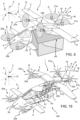
- the aircraft 1 also comprises ( Figures 3 and 4 ):
- the airframe 2 defines a compartment 60 and a plurality of openings 61 for access to the compartment 60.
- the compartment 60 may accommodate crew or passengers, or instrumentation or cargo to be transported, depending on how the aircraft is used 1.
- the openings 61 are located at sidewalls 62 of the airframe 3.
- the openings 61 are, moreover, arranged in a zone 63 which is delimited along the axis Y between the half-wings 3 and the aerodynamic surfaces 9.
- the aircraft 1 When it is arranged on the ground in the first configuration, the aircraft 1 defines an aisle 64 for access to the opening 61.
- the aisle 64 is delimited along the axis Y between the half-wings 3 and the aerodynamic surfaces 9 and parallel to the axes B, C between the ground and the supports 32a, 32b of the rotors 22a, 22b arranged in the second position ( Figure 5 ).
- the aisle 64 is clear and easily accessible during boarding/disembarking of passengers and/or loading/unloading of baggage.
- the aircraft 1 is controlled as follows.
- control unit 71 is programmed to command the rotors 20a, 20b, 21a, 21b, 22a, 22b so that the thrusts T1, T3, T5 are higher (lower) than the thrusts T2, T4, T6.
- the rotors 20a, 20b, 21a, 21b, 22a, 22b are commanded by the control unit 71 so as to increase (decrease) the thrusts T1, T3, T5 and to decrease (increase) the thrusts T2, T4, T6.
- control unit 71 is programmed to command the rotors 20a, 20b, 21a, 21b, 22a, 22b so that the thrusts T1, T2 are equal to each other higher than (lower than) the thrusts T3, T4 equal to each other.
- the rotors 20a, 20b, 21a, 21b are commanded so as to increase (decrease) the thrusts T1, T2 and to decrease (increase) the thrusts T3, T4.
- control unit 71 is programmed to orient the axis F of the rotor 22a towards (opposite side of) the nose 4 and the axis G of the rotor 22b towards (opposite side of) the tail 5.
- This generates two components of the thrusts T5, T6 that are parallel to the axis Y and discordant to each other which generate a torque and a consequent rotation of the aircraft around the axis Z.
- aircraft 1 is controlled as follows.
- control unit 71 is programmed to command the rotors 20a, 20b so that the respective thrusts T1, T2 ensure the correct trimming of the aircraft 1 - that is, the correct adjustment of the overall lift/downforce value depending on the required speed and weight conditions of the aircraft 1 - while and deactivates the rotors T5, T6 so that the thrusts T3, T4 are zero.
- control unit 71 is programmed to command the rotors 20a, 20b so that the thrust T1 is higher (lower) than the thrust T2.
- the rotors 20a, 20b are commanded to increase (decrease) thrust T1 and to decrease (increase) thrust T2.
- control unit 71 is programmed to command the rotors 20a, 20b, 22a, 22b so as to increase (decrease) the thrusts T1, T2 equal to each other and to adjust the thrusts T5, T6 equal to each other.
- control unit 71 commands the rotors 22a, 22b so that the thrust T1 is greater (lower) than the thrust T6.
- the rotors 22a, 22b are controlled by the control unit 71 so that the thrust T5 is greater (lower) than the thrust T6.
- the control unit 71 is, moreover, programmed to reduce the thrusts T1, T2; T3, T4 of the rotors 20a, 20b; 21a, 21b as the axes F, G of the rotors 22a, 22b progressively approach a condition of parallelism with the axis Y and the speed of the aircraft 1 increases.
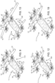
- the aircraft 1 has a modular conformation and is adapted to be reconfigured according to the operational needs so as to assume a plurality of different architectures.
- the aircraft 1 can assume:
- the aircraft 1 comprises:
- the core 100 comprises, in turn:
- the core 100 comprises the root portions 11, 17 of the half-wings 3 and the aerodynamic surfaces 9, respectively.
- the system 70 comprises, in more detail ( Figure 11 ):
- the system 70 further comprises a plurality of electric batteries 81, which electrically power the electric motors 72a, 72b, 73a, 73b, 74a, 74b.
- the module 110 provides the aircraft 1 with the first architecture.
- the module 110 defines the compartment 60, which forms a compartment for the passengers and relative baggage.
- the compartment 60 is accessible through the air 64 for the operations of passenger boarding/disembarking and baggage loading/unloading.
- the modules 120, 130 provide the aircraft 1 with the second and third architecture, respectively.
- the module 120, 130 defines the compartment 60 for passengers and relative baggage.
- the compartment 60 is accessible through the aisle 64.
- the module 120, 130 comprises a hybrid propulsion system 75 ( Figures 14 and 15 ), which comprises the components of the system 70.
- the system 75 of the modules 120, 130 comprises, in particular:
- the section 76 comprises, in turn:
- the section 77 comprises, in turn:
- the heat engine 90 has a maximum power that is greater than the heat engine 80.
- the generators 91 have a maximum power that is greater than the generators 82.
- the control unit 71 is programmed to electrically connect either the generators 91 or the batteries 81 to the electric motors 72a, 72b, 73a, 73b, 74a, 74b.
- control unit 71 is programmed to electrically connect both generators 82, 91 powered by respective heat engines 80, 90 to the corresponding electric motors 72a, 72b, 73a, 73b, 74a, 74b.
- the control unit 71 is programmed to connect the heat engine 80.
- the heat engine 80 drives, in turn, the generator 82, which electrically powers the electric motors 72a, 72b, 73a, 73b, 74a, 74b and, preferably, to recharge the batteries 81 through the generator 82.
- control unit 71 is programmed to electrically connect the batteries 81 to the electric motors 72a, 72b, 73a, 73b, 74a, 74b.
- the module 140 provides the aircraft 1 with the fourth architecture.
- the module 140 comprises, similarly to the module 130, the heat engines 80 and 90 and the electric generators 91, 82.
- the system 75 of the module 140 is totally identical to that of the modules 120, 130.
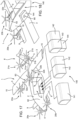
- the module 140 also defines a cargo housing compartment 60 equipped with a sliding ramp that can be folded into the compartment 60.
- the compartment 60 houses ( Figures 17 and 18 ):
- Each module 110, 120, 130, 140 further comprises ( Figures 9, 12, 13 and 19 ) :
- the half-wings 3 and the aerodynamic surfaces 9 are optimised according to the flight envelope that are characteristic of the first, second, third and fourth architecture.
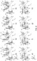
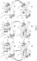
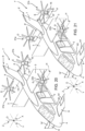
- the aircraft 1 lands and takes off arranged in the first configuration with the rotors 22a, 22b arranged in the first position wherein the relative thrusts T5, T6 are directed parallel to the axis Z ( Figure 6a ).
- the aircraft 1 moves forward in the second configuration with the rotors 22a, 22b arranged in the second position wherein the respective thrusts T5, T6 are arranged parallel to the axis Y.
- the lift required to sustain the aircraft 1 is delivered by the rotors 20a, 20b; 21a, 21b and 22a, 22b.
- control unit 71 is programmed to command the rotors 20a, 20b, 21a, 21b, 22a, 22b so that the thrusts T1, T3, T5 are higher (lower) than the thrusts T2, T4, T6.
- control unit 71 is programmed to command the rotors 20a, 20b, 21a, 21b, 22a, 22b so that the thrusts T1, T2 are equal to each other higher (lower) than the thrusts T3, T4 equal to each other.
- control unit 71 is programmed to command the rotor 22a so that the axis F is oriented towards (opposite side of) the nose 4 and the rotor 22b so that the axis G is oriented towards (opposite side of) the tail 5.
- This generates two components of the thrusts T5, T6 that are parallel to the axis Y and discordant to each other which generate a torque and a consequent rotation of the aircraft around the axis Z.
- control unit 71 is programmed to reduce the thrusts T1, T2; T3, T4 of the rotors 20a, 20b; 21a, 21b as the axes F, G of the rotors 22a, 22b progressively approach a condition of parallelism with the axis Y and the speed of the aircraft 1 increases.
- the lift required to sustain the aircraft 1 is mostly provided by the half-wings 3.
- the rotors 20a, 20b; 21a, 21b can be optionally deactivated.
- the thrusts T1, T2 of the rotors 20a, 20b ensure the correct trimming of the aircraft 1 - i.e. the adjustment of the overall lift/downforce value under the required speed and weight conditions of the aircraft 1 - while the rotors 21a, 21b are deactivated so that the thrusts T3, T4 are zero.
- the rotors 20a, 20b are controlled by the control unit 71 so that the thrust T1 is higher (lower) than the thrust T2.
- the rotors 20a, 20b, 22a, 22b are controlled by the control unit 71, so as to increase (decrease) the thrusts T1, T2 equal to each other and to adjust the thrusts T5, T6 equal to each other.
- the rotors 22a, 22b are controlled by the control unit 71 so that the thrust T1 is greater (lower) than the thrust T6.
- the appendages 14 may be moved with respect to the relative aerodynamic surfaces 8 in a concordant or discordant manner with each other, and thus contribute to the control of the aircraft 1.
- the concordant movement of the appendages 14 results in a torque around the axis X and increases the second lift value.
- the control unit 71 rotates the rotors 22a, 22b in the respective first positions, and increases the thrusts T1, T2, T3, T4 of the rotors 20a, 20b, 21a, 21b which are optionally still operating and the thrusts, T5, T6 of the rotors, 22a, 22b ( Figure 7a ).
- the control unit 71 rotates the rotors 22a, 22b in the respective first positions, and increases the thrusts T1, T2, T3, T4 of the rotors 20a, 20b, 21a, 21b and the thrusts T5, T6 of the rotors 22a, 22b which are optionally still operating ( Figure 7b ).
- the aircraft 1 assumes the first configuration, wherein it can land safely.
- control unit 71 rotates the rotors 22a, 22b in the respective second positions ( Figure 7f ). In this way, the aircraft 1 can efficiently glide in order to reach a landing site.
- the aircraft 1 is used for urban mobility and passenger transport applications within the compartment 60 and the module 110 is interfaced with the core 100.
- the passengers and the baggage access the compartment 60 through the aisle 64 when the aircraft 1 is arranged in the first configuration.
- the control unit 71 receives at input the control signals of the aircraft 1 and consequently commands the electric motors 72a, 72b, 73a, 73b, 74a, 74b so as to obtain respective desired thrusts T1, T2, T3, T4, T5, T6 from the respective rotors 20a, 20b, 21a, 21b, 22a, 22b.
- the batteries 81 electrically power the electric motors 72a, 72b, 73a, 73b, 74a, 74b.
- the aircraft 1 realizes a Utility category aircraft or is deployed for VIP passenger transport, and the respective modules 120, 130 are interfaced with the core 100.
- the heat engine 90 When the aircraft 1 is in the first configuration for a short time interval, the heat engine 90 provides mechanical power to the generators 91.
- the batteries 81 and the generators 91 electrically power the electric motors 72a, 72b, 73a, 73b, 74a, 74b, which drive the respective rotors 20a, 20b, 21a, 21b, 22a, 22b into rotation.
- both heat engines 80, 90 provide mechanical power to the respective generators 82, 91.
- the generators 82, 91 are in turn electrically connected to the electric motors 72a, 72b, 73a, 73b, 74a, 74b which drive the respective rotors 20a, 20b, 21a, 21b, 22a, 22b into rotation.
- the heat engine 90 When the aircraft 1 transits to the second configuration wherein the power required for cruise flight is lower than that required in the first configuration, the heat engine 90 is deactivated and the heat engine 80 alone drives the electric motors 72a, 72b, 73a, 73b, 74a, 74b and recharges the batteries 81.
- the batteries 81 power the electric motors 72a, 72b, 73a, 73b, 74a, 74b exclusively.
- the aircraft 1 is deployed as a remotely operated aircraft capable of carrying out long duration missions.
- the sub-module 141, the sub-modules 142 or a sub-module 141 and a sub-module 143 are housed inside the compartment 60.
- 1' denotes an aircraft according to a further embodiment of the invention.
- the aircraft 1' is similar to the aircraft 1 and will be described below only insofar as it differs from the latter; equal or equivalent parts of the lubrication systems 1, 1' will be marked, where possible, by the same reference numbers.
- the aircraft 1' differs from the aircraft 1 in that the tail portion 6' is cruciform and in that the supports 31a, 31b project cantilevered from respective sidewalls of the fin 7.
- the aerodynamic surfaces 8' are arranged inferiorly to the respective rotors 21a, 21b.
- the aerodynamic surfaces 8' support the respective rotors 21a, 21b and have respective fairings 13' that are movable between:
- the fairings 13' at least partially accommodate the respective supports 31a, 31b and are movable with respect to said supports 31a, 31b between the respective first and second position.
- the aircraft 1' also differs from the aircraft 1 in that the appendages 14' are arranged on respective aerodynamic surfaces 9 instead of on respective aerodynamic surfaces 8'.
- the operation of the aircraft 1' differs from that of the aircraft 1 in that the fairings 13' are moved with respect to the relative aerodynamic surfaces 8' from the respective first to the respective second positions and vice versa, when the aircraft 1' transits from the second to the first configuration and vice versa.
- the rotors 22a, 22b are arranged spaced apart from the ends 15 of the respective half-wings 3, proceeding along the extension direction of the respective half-wings 3.
- the aircraft 1, 1' further comprises four rotors 20a, 20b, 21a, 21b with respective fixed axes B, C, D, E and respective thrusts T1, T2, T3, T4 that are adjustable independently of each other, and two rotors 22a, 22b with respective tilting axes F, G and thrusts T5, T6 adjustable independently of each other.
- the aircraft 1, 1' can operate efficiently either in the first configuration or in the second configuration, and can control the roll, yaw and pitch movements with a lower number of rotors and relative components than the known solutions and discussed in the introductory part of the present description, with obvious advantages in terms of cost and simplicity of maintenance.
- the control unit 71 returns the rotors 22a, 22b optionally still operational to the respective first positions and increases the thrusts T1, T2, T3, T4, T5, T6 of the rotors 20a, 20b, 21a, 21b, 22a, 22b that are optionally still operational.
- the aircraft 1, 1' is arranged in the first configuration and can land safely.
- the aircraft 1, 1' achieves the aforesaid manoeuvrability by using rotors 20a, 20b, 21a, 21b, 22a, 22b with fixed pitch and, therefore, particularly economical and easy to maintain.
- the aircraft 1, 1' can fly in trimmed configuration and perform the aforesaid pitch, yaw and roll manoeuvres, simply by adjusting the thrusts T1, T2, T3, T4, T5, T6 of the rotors 20a, 20b, 21a, 21b, 22a, 22b and without the need to use the appendages 14.
- the aircraft 1, 1' does not need the appendages 14, 14'.
- the appendages 14, 14' if provided for redundancy, can be realized with particularly reduced widths and with particularly small working angles, further simplifying the embodiment complexity of the aircraft 1, 1'.
- the rotors 20a, 20b are arranged anteriorly to the aerodynamic surfaces 8.
- the rotors 22a, 22b are arranged superiorly to the respective half-wings 3 when the aircraft 1, 1' is in the first configuration and parked on the ground.
- the aisle 64 for access to the compartment 60 is thus clear and easily accessible, facilitating the boarding/disembarking of passengers and the loading/unloading of goods.
- the fin 7 extends either above or below the airframe 2.
- the aircraft 1 has high lateral stability.
- the fin 7 and the surfaces 9 carry respective carriages 45, 46, thus avoiding the need for additional support elements dedicated to them.
- a reduction in the aerodynamic resistance is achieved and access to the belly of the airframe 2 is left free.
- the fairings 13' are moved with respect to the relevant aerodynamic surfaces 8' from the respective first to the respective second positions and vice versa, when the aircraft 1' transits from the second to the first configuration and vice versa. In this way, the interference between the downward flow generated by the rotors 21a', 21b' and the aerodynamic surfaces 8' is reduced, with a consequent increase in the figure of merit in the hovering flight of the aircraft 1' arranged in the first configuration.
- appendages 14 could be arranged on respective aerodynamic surfaces 9 instead of aerodynamic surfaces 8.
- the aircraft 1, 1' may not comprise the aerodynamic surfaces 8, 8'.
- the supports 31a, 31b may project cantilevered posteriorly from respective half-wings 3 instead of from respective sidewalls 62 of the airframe 2.
- the axes B, C; D, E may not be parallel to the axis Z and may be inclined with respect to the axis Z by an angle ranging between - 15 and + 15 degrees.
- the axes B, C (D, E) could converge in the axis Z above or below the airframe 2.
- At least some of or all of the rotors 20a, 20b, 21a, 21b, 22a, 22b could have variable pitch, at least some of them.
- the aircraft 1, 1' may comprise either the appendages 14 arranged on the aerodynamic surfaces 8, 8' or the appendages 14' arranged on the aerodynamic surfaces 9, 9'
- the aircraft 1, 1' could perform the aforesaid pitch, yaw and roll manoeuvres, using both appendages 14, 14'.
- the appendages 14, 14' can be operated as required by mixing their movement with the movement of the respective aerodynamic surfaces 9, 8.
- a movement of an appendage 14 corresponds to a predetermined movement of an appendage 14' and vice versa.
Landscapes
- Engineering & Computer Science (AREA)
- Aviation & Aerospace Engineering (AREA)
- Chemical & Material Sciences (AREA)
- Combustion & Propulsion (AREA)
- Mechanical Engineering (AREA)
- Transmission Devices (AREA)
- Window Of Vehicle (AREA)
- Footwear And Its Accessory, Manufacturing Method And Apparatuses (AREA)
- Toys (AREA)
- Mechanical Control Devices (AREA)
Claims (11)
- Verwandelbares Luftfahrzeug (1, 1'), das Folgendes umfasst:- ein Flugwerk (2), das eine erste Längsachse (Y) des Luftfahrzeugs (1, 1') definiert;- ein Paar Halbflügel (3), die auf jeweiligen einander gegenüberliegenden Seiten von Seitenwänden (62) des Flugwerks (2) angeordnet sind und im Gebrauch einen ersten Auftriebs- oder Abtriebswert erzeugen;- einen ersten und einen zweiten Rotor (20a, 20b), die um eine zweite bzw. eine dritte Achse (B, C) rotieren können und in Bezug auf das Flugwerk (2) feststehend sind und unabhängig voneinander betreibbar sind, um unabhängig voneinander einen ersten bzw. einen zweiten Schubwert (T1, T2) zu erzeugen;- einen dritten und einen vierten Rotor (21a, 21b), die um eine vierte bzw. eine fünfte Achse (D, E) rotieren können und in Bezug auf das Flugwerk (2) feststehend sind und unabhängig voneinander betreibbar sind, um voneinander unabhängig einen dritten bzw. einen vierten Schubwert (T3, T4) zu erzeugen;wobei die zweite und die dritte Achse (B, C) auf jeweiligen Seiten einer ersten und einer zweiten Seitenwand (62), die einander gegenüberliegen, des Flugwerks (2) in Bezug auf die erste Achse (Y) symmetrisch angeordnet sind;wobei die vierte und die fünfte Achse (D, E) auf jeweiligen Seiten der ersten und der zweiten Seitenwand (62) des Flugwerks (2) in Bezug auf die erste Achse (Y) symmetrisch angeordnet sind;wobei das Luftfahrzeug (1, 1') ferner Folgendes umfasst:- einen fünften und einen sechsten Rotor (22a, 22b), die durch die jeweiligen Halbflügel (3) getragen werden, die um eine sechste bzw. eine siebte Achse (F, G) rotieren können, in Bezug auf das Flugwerk (2) geneigt werden können und unabhängig voneinander betreibbar sind, um unabhängig voneinander einen fünften bzw. einen sechsten Schubwert (T5, T6) zu erzeugen;wobei die sechste und die siebte Achse (F, G) auf jeweiligen Seiten der ersten und der zweiten Seitenwand (62) des Flugwerks (2) in Bezug auf die erste Achse (Y) symmetrisch angeordnet sind;wobei das Luftfahrzeug (1, 1') umgeschaltet werden kann zwischen:- einer ersten Schwebe- oder Start/Lande-Flugkonfiguration, wobei die sechste und die siebte Achse (F, G) senkrecht zur ersten Achse (Y) angeordnet sind; und- einer zweiten Vorwärtsflugkonfiguration, wobei die sechste und die siebte Achse (F, G) parallel zur ersten Achse (Y) oder in Bezug auf die erste Achse (Y) geneigt angeordnet sind;gekennzeichnet durch das Umfassen erster Träger (32a, 32b), die ausgelegt sind, den fünften und den sechsten Rotor (22a, 22b) in Bezug auf die zugehörigen Halbflügel (3) zu tragen; wobei die ersten Träger (32a, 32b) in einem Abstand von jeweiligen freien Enden (15) der jeweiligen Halbflügel (3) gemäß einer Erstreckungsrichtung der Halbflügel (3) angeordnet sind; wobei der fünfte und der sechste Rotor (22a, 22b) zwischen dem ersten und den zweiten Rotor (20a, 20b) und dem dritten und dem vieren Rotor (21a, 21b) entlang der ersten Achse (Y) eingefügt sind;wobei die erste, die dritte und die fünfte Achse (B, D, F) entlang der ersten Achse (Y) aufeinander ausgerichtet sind, wenn das Luftfahrzeug (1, 1') in der ersten Konfiguration angeordnet ist;- wobei die zweite, die vierte und die sechste Achse (C, E, G) entlang der ersten Achse (Y) aufeinander ausgerichtet sind, wenn das Luftfahrzeug (1, 1') in der ersten Konfiguration angeordnet ist;wobei die zweite, die dritte, die vierte und die fünfte Achse (B, C, D, E) zueinander parallel sind.
- Luftfahrzeug nach Anspruch 1, wobei sich die ersten Träger (32a, 32b) in Bezug auf eine reguläre Betriebsposition des Luftfahrzeugs (1, 1'), das im Gebrauch in der zweiten Konfiguration angeordnet ist, vor den Halbflügeln (3) erstrecken.
- Luftfahrzeug nach Anspruch 1 oder 2, wobei der fünfte und der sechste Rotor (22a, 22b) über den jeweiligen Halbflügeln (3) und vor den jeweiligen Halbflügeln (3) angeordnet sind, wenn sich das Luftfahrzeug (1, 1') in der ersten Konfiguration befindet und in Bezug auf die reguläre Betriebsposition.
- Luftfahrzeug nach einem der vorhergehenden Ansprüche, wobei das Luftfahrzeug (1, 1') lediglich einen fünften Rotor (22a) und lediglich einen sechsten Rotor (22b) umfasst.
- Luftfahrzeug nach einem der vorhergehenden Ansprüche, das ferner Folgendes umfasst:- eine Seitenflosse (7), die an einem Heck (6) des Flugwerks (2) angeordnet ist; und- zweite Träger (31a, 31b), die vorgesehen sind, um den dritten und den vierten Rotor (21a, 21b) in Bezug auf das Flugwerk (2) zu tragen, wobei die zweiten Träger (31a, 31b) in Bezug auf eine reguläre Betriebsposition des Luftfahrzeug (1, 1'), das im Gebrauch in der zweiten Konfiguration angeordnet ist, auf jeweiligen einander gegenüberliegenden Seitenwänden (62) der Seitenflosse (7) und hinter den jeweiligen Halbflügeln (3) angeordnet sind.
- Luftfahrzeug nach Anspruch 5, wobei sich die Seitenflosse (7) sowohl auf der oberen als auch auf der unteren Seite des Flugwerks (2) erstreckt; und/oder
wobei die Seitenflosse (7) ein erstes Fahrwerk (46) trägt. - Luftfahrzeug nach Anspruch 6, wobei die Seitenflosse (7) ein Paar erster aerodynamischer Flächen (8, 8') umfasst, die feststehend sind und freitragend von jeweiligen einander gegenüberliegenden Seiten (62) der Seitenflosse (7) vorstehen; wobei die ersten aerodynamischen Flächen (8, 8') ausgelegt sind, im Gebrauch einen zweiten Auftriebs/Abtriebs-Wert zu erzeugen.
- Luftfahrzeug nach Anspruch 7, wobei der dritte und der vierte Rotor (21a, 21b) in Bezug auf eine reguläre Betriebsposition des Luftfahrzeugs (1), das im Gebrauch in der zweiten Konfiguration angeordnet ist, unter den ersten aerodynamischen Flächen (8) angeordnet sind; und/oderwobei die zweiten Rotoren (21a, 21b) in Bezug auf eine reguläre Betriebsposition des Luftfahrzeugs (1'), das im Gebrauch in der zweiten Konfiguration angeordnet ist, höherstehend als die ersten aerodynamischen Flächen (8') angeordnet sind; wobei die ersten Flächen (8') zumindest teilweise in Bezug auf die Seitenflosse (7) zwischen einer ersten Position und einer zweiten Position bewegt werden können, die eingenommen werden, wenn das Luftfahrzeug (1') in der ersten bzw. der zweiten Konfiguration angeordnet ist; wobei die ersten Flächen (8') jeweilige erste Bereiche und jeweilige zweite Bereiche mit einer geringeren Ausdehnung als die jeweiligen ersten Bereiche aufweisen; wobei die zweiten Bereiche und die ersten Bereiche tieferstehend zu den jeweiligen zweiten Rotoren (21a, 21b) angeordnet sind, wenn das Luftfahrzeug (1') im Gebrauch in der ersten bzw. der zweiten Konfiguration angeordnet ist; und/oderwobei die erste und die zweite Achse (B, C) im Gebrauch vor einem Ende (4) des Flugwerks (2) gegenüber der dritten und der vierten Achse (D, E) angeordnet sind; und/oderdas ferner Folgendes umfasst:- ein Paar zweiter aerodynamischer Flächen (9), die ausgelegt sind, dritte Auftriebs/Abtriebs-Werte bereitzustellen, und freitragend von jeweiligen gegenüberliegenden Seiten (62) des Flugwerks (2) vorstehen; wobei die zweiten aerodynamischen Flächen (9) ausgelegt sind, im Gebrauch einen dritten Auftriebs/Abtriebs-Wert zu erzeugen; und- dritte Träger (30a, 30b), die ausgelegt sind, den ersten und den zweiten Rotor (20a, 20b) zu tragen und die an den zweiten aerodynamischen Flächen (9) arretiert sind.
- Luftfahrzeug nach Anspruch 8, wobei die Halbflügel (3) entlang der ersten Achse (Y) zwischen der ersten und der zweiten aerodynamischen Fläche (8, 9) eingefügt sind; und/oder
das ferner dritte aerodynamische Steuerflächen (14) umfasst, die mit den jeweiligen zweiten aerodynamischen Flächen (9) beweglich verbunden sind oder mit den jeweiligen ersten aerodynamischen Flächen (8, 8') verbunden werden können. - Luftfahrzeug nach Anspruch 8 oder 9, wenn abhängig von Anspruch 5, wobei die zweiten aerodynamischen Flächen (9) ein zweites Fahrwerk (45) tragen.
- Luftfahrzeug nach einem der vorhergehenden Ansprüche, wobei:- der erste und/oder der zweite und/oder der dritte und/oder der vierte und/oder der fünfte und/oder der sechste Rotor (20a, 20b, 21a, 21b, 22a, 22b) eine festgelegte Längsneigung aufweisen; und/oderwobei der erste und/oder der zweite und/oder der dritte und/oder der vierte und/oder der fünfte und/oder der sechste Rotor (20a, 20b, 21a, 21b, 22a, 22b) elektrisch angetrieben werden.
Priority Applications (10)
| Application Number | Priority Date | Filing Date | Title |
|---|---|---|---|
| EP21180396.0A EP4105123B1 (de) | 2021-06-18 | 2021-06-18 | Umwandelbares schwebefähiges fluggerät und zugehöriges steuerungsverfahren |
| PCT/IB2022/054828 WO2022263947A1 (en) | 2021-06-18 | 2022-05-24 | Convertible aircraft capable of hovering |
| CN202280043289.8A CN117545689A (zh) | 2021-06-18 | 2022-05-24 | 能够悬停的转换型飞行器 |
| KR1020237044158A KR20240046116A (ko) | 2021-06-18 | 2022-05-24 | 호버링이 가능한 전환식 항공기 |
| BR112023025639-9A BR112023025639B1 (pt) | 2021-06-18 | 2022-05-24 | Aeronave conversível |
| CA3220722A CA3220722A1 (en) | 2021-06-18 | 2022-05-24 | Convertible aircraft capable of hovering |
| JP2023575608A JP2024522597A (ja) | 2021-06-18 | 2022-05-24 | ホバリングすることができるコンバーチブル航空機 |
| US18/567,968 US12358617B2 (en) | 2021-06-18 | 2022-05-24 | Convertible aircraft capable of hovering |
| AU2022294229A AU2022294229A1 (en) | 2021-06-18 | 2022-05-24 | Convertible aircraft capable of hovering |
| IL309087A IL309087B2 (en) | 2021-06-18 | 2022-05-24 | Convertible aircraft and hovering capability |
Applications Claiming Priority (1)
| Application Number | Priority Date | Filing Date | Title |
|---|---|---|---|
| EP21180396.0A EP4105123B1 (de) | 2021-06-18 | 2021-06-18 | Umwandelbares schwebefähiges fluggerät und zugehöriges steuerungsverfahren |
Publications (2)
| Publication Number | Publication Date |
|---|---|
| EP4105123A1 EP4105123A1 (de) | 2022-12-21 |
| EP4105123B1 true EP4105123B1 (de) | 2023-08-30 |
Family
ID=77274646
Family Applications (1)
| Application Number | Title | Priority Date | Filing Date |
|---|---|---|---|
| EP21180396.0A Active EP4105123B1 (de) | 2021-06-18 | 2021-06-18 | Umwandelbares schwebefähiges fluggerät und zugehöriges steuerungsverfahren |
Country Status (9)
| Country | Link |
|---|---|
| US (1) | US12358617B2 (de) |
| EP (1) | EP4105123B1 (de) |
| JP (1) | JP2024522597A (de) |
| KR (1) | KR20240046116A (de) |
| CN (1) | CN117545689A (de) |
| AU (1) | AU2022294229A1 (de) |
| CA (1) | CA3220722A1 (de) |
| IL (1) | IL309087B2 (de) |
| WO (1) | WO2022263947A1 (de) |
Families Citing this family (3)
| Publication number | Priority date | Publication date | Assignee | Title |
|---|---|---|---|---|
| EP4105125B1 (de) * | 2021-06-18 | 2023-09-06 | Leonardo S.p.a. | Eine reihe von umwandelbaren luftfahrzeugen mit fähigkeit zum schweben und verfahren zur konfigurierung eines umwandelbaren luftfahrzeugs mit fähigkeit zum fliegen |
| EP4653316A1 (de) | 2024-05-24 | 2025-11-26 | Leonardo S.p.a. | Umwandelbares luftfahrzeug, das schweben kann |
| EP4653315A1 (de) | 2024-05-24 | 2025-11-26 | Leonardo S.p.a. | Umwandelbares luftfahrzeug, das schweben kann |
Family Cites Families (9)
| Publication number | Priority date | Publication date | Assignee | Title |
|---|---|---|---|---|
| US8251305B2 (en) * | 2008-02-13 | 2012-08-28 | Textron Innovations Inc. | Rotorcraft with variable incident wing |
| US9278205B2 (en) | 2013-03-13 | 2016-03-08 | Carefusion 303, Inc. | Collapsible valve with internal dimples |
| US20160236775A1 (en) * | 2015-02-18 | 2016-08-18 | Siniger LLC | Vertical takeoff and landing aircraft |
| US9561849B2 (en) * | 2015-02-19 | 2017-02-07 | Amazon Technologies, Inc. | Vehicle configuration with motors that rotate between a lifting position and a thrusting position |
| US10011349B2 (en) | 2016-08-31 | 2018-07-03 | Bell Helicopter Textron Inc. | Tiltrotor aircraft having rotatable wing extensions |
| US20180215465A1 (en) | 2017-01-31 | 2018-08-02 | Joseph Raymond RENTERIA | Rotatable thruster aircraft with separate lift thrusters |
| IL263301B2 (en) | 2018-11-25 | 2023-09-01 | Israel Aerospace Ind Ltd | Aircraft and the method of operation of aircraft |
| EP3656669B1 (de) * | 2018-11-26 | 2021-01-13 | AIRBUS HELICOPTERS DEUTSCHLAND GmbH | Senkrecht startendes und landendes multirotorflugzeug mit mindestens acht schuberzeugungseinheiten |
| WO2020141513A2 (en) * | 2018-12-31 | 2020-07-09 | Polarity Mobility Av Ltd. | Evtol aircraft |
-
2021
- 2021-06-18 EP EP21180396.0A patent/EP4105123B1/de active Active
-
2022
- 2022-05-24 JP JP2023575608A patent/JP2024522597A/ja active Pending
- 2022-05-24 WO PCT/IB2022/054828 patent/WO2022263947A1/en not_active Ceased
- 2022-05-24 CA CA3220722A patent/CA3220722A1/en active Pending
- 2022-05-24 CN CN202280043289.8A patent/CN117545689A/zh active Pending
- 2022-05-24 US US18/567,968 patent/US12358617B2/en active Active
- 2022-05-24 IL IL309087A patent/IL309087B2/en unknown
- 2022-05-24 AU AU2022294229A patent/AU2022294229A1/en active Pending
- 2022-05-24 KR KR1020237044158A patent/KR20240046116A/ko active Pending
Also Published As
| Publication number | Publication date |
|---|---|
| JP2024522597A (ja) | 2024-06-21 |
| AU2022294229A1 (en) | 2023-12-14 |
| CA3220722A1 (en) | 2022-12-22 |
| KR20240046116A (ko) | 2024-04-08 |
| IL309087B1 (en) | 2025-06-01 |
| IL309087B2 (en) | 2025-10-01 |
| WO2022263947A1 (en) | 2022-12-22 |
| BR112023025639A2 (pt) | 2024-02-27 |
| EP4105123A1 (de) | 2022-12-21 |
| IL309087A (en) | 2024-02-01 |
| US12358617B2 (en) | 2025-07-15 |
| US20240270378A1 (en) | 2024-08-15 |
| CN117545689A (zh) | 2024-02-09 |
Similar Documents
| Publication | Publication Date | Title |
|---|---|---|
| EP4105124B1 (de) | Eine reihe von umwandelbaren luftfahrzeugen mit fähigkeit zum schweben und verfahren zur konfigurierung eines umwandelbaren luftfahrzeugs mit fähigkeit zum fliegen | |
| EP4105125B1 (de) | Eine reihe von umwandelbaren luftfahrzeugen mit fähigkeit zum schweben und verfahren zur konfigurierung eines umwandelbaren luftfahrzeugs mit fähigkeit zum fliegen | |
| US12358617B2 (en) | Convertible aircraft capable of hovering | |
| US12503245B2 (en) | Fuselage for a convertible aircraft capable of hovering | |
| US12552529B2 (en) | Convertible aircraft capable of hovering | |
| BR112023025639B1 (pt) | Aeronave conversível | |
| BR112023025657B1 (pt) | Série de aeronaves, e, método para configurar uma aeronave | |
| BR112023025636B1 (pt) | Série de aeronaves, e, método para configurar uma aeronave |
Legal Events
| Date | Code | Title | Description |
|---|---|---|---|
| PUAI | Public reference made under article 153(3) epc to a published international application that has entered the european phase |
Free format text: ORIGINAL CODE: 0009012 |
|
| STAA | Information on the status of an ep patent application or granted ep patent |
Free format text: STATUS: REQUEST FOR EXAMINATION WAS MADE |
|
| 17P | Request for examination filed |
Effective date: 20211223 |
|
| AK | Designated contracting states |
Kind code of ref document: A1 Designated state(s): AL AT BE BG CH CY CZ DE DK EE ES FI FR GB GR HR HU IE IS IT LI LT LU LV MC MK MT NL NO PL PT RO RS SE SI SK SM TR |
|
| GRAP | Despatch of communication of intention to grant a patent |
Free format text: ORIGINAL CODE: EPIDOSNIGR1 |
|
| STAA | Information on the status of an ep patent application or granted ep patent |
Free format text: STATUS: GRANT OF PATENT IS INTENDED |
|
| INTG | Intention to grant announced |
Effective date: 20230320 |
|
| GRAS | Grant fee paid |
Free format text: ORIGINAL CODE: EPIDOSNIGR3 |
|
| GRAA | (expected) grant |
Free format text: ORIGINAL CODE: 0009210 |
|
| STAA | Information on the status of an ep patent application or granted ep patent |
Free format text: STATUS: THE PATENT HAS BEEN GRANTED |
|
| RAP3 | Party data changed (applicant data changed or rights of an application transferred) |
Owner name: LEONARDO S.P.A. |
|
| AK | Designated contracting states |
Kind code of ref document: B1 Designated state(s): AL AT BE BG CH CY CZ DE DK EE ES FI FR GB GR HR HU IE IS IT LI LT LU LV MC MK MT NL NO PL PT RO RS SE SI SK SM TR |
|
| REG | Reference to a national code |
Ref country code: GB Ref legal event code: FG4D |
|
| REG | Reference to a national code |
Ref country code: CH Ref legal event code: EP |
|
| REG | Reference to a national code |
Ref country code: DE Ref legal event code: R096 Ref document number: 602021004637 Country of ref document: DE |
|
| REG | Reference to a national code |
Ref country code: IE Ref legal event code: FG4D |
|
| P01 | Opt-out of the competence of the unified patent court (upc) registered |
Effective date: 20231005 |
|
| REG | Reference to a national code |
Ref country code: LT Ref legal event code: MG9D |
|
| REG | Reference to a national code |
Ref country code: NL Ref legal event code: MP Effective date: 20230830 |
|
| REG | Reference to a national code |
Ref country code: AT Ref legal event code: MK05 Ref document number: 1605137 Country of ref document: AT Kind code of ref document: T Effective date: 20230830 |
|
| PG25 | Lapsed in a contracting state [announced via postgrant information from national office to epo] |
Ref country code: GR Free format text: LAPSE BECAUSE OF FAILURE TO SUBMIT A TRANSLATION OF THE DESCRIPTION OR TO PAY THE FEE WITHIN THE PRESCRIBED TIME-LIMIT Effective date: 20231201 |
|
| PG25 | Lapsed in a contracting state [announced via postgrant information from national office to epo] |
Ref country code: IS Free format text: LAPSE BECAUSE OF FAILURE TO SUBMIT A TRANSLATION OF THE DESCRIPTION OR TO PAY THE FEE WITHIN THE PRESCRIBED TIME-LIMIT Effective date: 20231230 |
|
| PG25 | Lapsed in a contracting state [announced via postgrant information from national office to epo] |
Ref country code: SE Free format text: LAPSE BECAUSE OF FAILURE TO SUBMIT A TRANSLATION OF THE DESCRIPTION OR TO PAY THE FEE WITHIN THE PRESCRIBED TIME-LIMIT Effective date: 20230830 Ref country code: RS Free format text: LAPSE BECAUSE OF FAILURE TO SUBMIT A TRANSLATION OF THE DESCRIPTION OR TO PAY THE FEE WITHIN THE PRESCRIBED TIME-LIMIT Effective date: 20230830 Ref country code: NO Free format text: LAPSE BECAUSE OF FAILURE TO SUBMIT A TRANSLATION OF THE DESCRIPTION OR TO PAY THE FEE WITHIN THE PRESCRIBED TIME-LIMIT Effective date: 20231130 Ref country code: LV Free format text: LAPSE BECAUSE OF FAILURE TO SUBMIT A TRANSLATION OF THE DESCRIPTION OR TO PAY THE FEE WITHIN THE PRESCRIBED TIME-LIMIT Effective date: 20230830 Ref country code: LT Free format text: LAPSE BECAUSE OF FAILURE TO SUBMIT A TRANSLATION OF THE DESCRIPTION OR TO PAY THE FEE WITHIN THE PRESCRIBED TIME-LIMIT Effective date: 20230830 Ref country code: IS Free format text: LAPSE BECAUSE OF FAILURE TO SUBMIT A TRANSLATION OF THE DESCRIPTION OR TO PAY THE FEE WITHIN THE PRESCRIBED TIME-LIMIT Effective date: 20231230 Ref country code: HR Free format text: LAPSE BECAUSE OF FAILURE TO SUBMIT A TRANSLATION OF THE DESCRIPTION OR TO PAY THE FEE WITHIN THE PRESCRIBED TIME-LIMIT Effective date: 20230830 Ref country code: GR Free format text: LAPSE BECAUSE OF FAILURE TO SUBMIT A TRANSLATION OF THE DESCRIPTION OR TO PAY THE FEE WITHIN THE PRESCRIBED TIME-LIMIT Effective date: 20231201 Ref country code: FI Free format text: LAPSE BECAUSE OF FAILURE TO SUBMIT A TRANSLATION OF THE DESCRIPTION OR TO PAY THE FEE WITHIN THE PRESCRIBED TIME-LIMIT Effective date: 20230830 Ref country code: AT Free format text: LAPSE BECAUSE OF FAILURE TO SUBMIT A TRANSLATION OF THE DESCRIPTION OR TO PAY THE FEE WITHIN THE PRESCRIBED TIME-LIMIT Effective date: 20230830 |
|
| PG25 | Lapsed in a contracting state [announced via postgrant information from national office to epo] |
Ref country code: PL Free format text: LAPSE BECAUSE OF FAILURE TO SUBMIT A TRANSLATION OF THE DESCRIPTION OR TO PAY THE FEE WITHIN THE PRESCRIBED TIME-LIMIT Effective date: 20230830 Ref country code: NL Free format text: LAPSE BECAUSE OF FAILURE TO SUBMIT A TRANSLATION OF THE DESCRIPTION OR TO PAY THE FEE WITHIN THE PRESCRIBED TIME-LIMIT Effective date: 20230830 |
|
| PG25 | Lapsed in a contracting state [announced via postgrant information from national office to epo] |
Ref country code: ES Free format text: LAPSE BECAUSE OF FAILURE TO SUBMIT A TRANSLATION OF THE DESCRIPTION OR TO PAY THE FEE WITHIN THE PRESCRIBED TIME-LIMIT Effective date: 20230830 |
|
| PG25 | Lapsed in a contracting state [announced via postgrant information from national office to epo] |
Ref country code: SM Free format text: LAPSE BECAUSE OF FAILURE TO SUBMIT A TRANSLATION OF THE DESCRIPTION OR TO PAY THE FEE WITHIN THE PRESCRIBED TIME-LIMIT Effective date: 20230830 Ref country code: RO Free format text: LAPSE BECAUSE OF FAILURE TO SUBMIT A TRANSLATION OF THE DESCRIPTION OR TO PAY THE FEE WITHIN THE PRESCRIBED TIME-LIMIT Effective date: 20230830 Ref country code: ES Free format text: LAPSE BECAUSE OF FAILURE TO SUBMIT A TRANSLATION OF THE DESCRIPTION OR TO PAY THE FEE WITHIN THE PRESCRIBED TIME-LIMIT Effective date: 20230830 Ref country code: EE Free format text: LAPSE BECAUSE OF FAILURE TO SUBMIT A TRANSLATION OF THE DESCRIPTION OR TO PAY THE FEE WITHIN THE PRESCRIBED TIME-LIMIT Effective date: 20230830 Ref country code: DK Free format text: LAPSE BECAUSE OF FAILURE TO SUBMIT A TRANSLATION OF THE DESCRIPTION OR TO PAY THE FEE WITHIN THE PRESCRIBED TIME-LIMIT Effective date: 20230830 Ref country code: CZ Free format text: LAPSE BECAUSE OF FAILURE TO SUBMIT A TRANSLATION OF THE DESCRIPTION OR TO PAY THE FEE WITHIN THE PRESCRIBED TIME-LIMIT Effective date: 20230830 Ref country code: PT Free format text: LAPSE BECAUSE OF FAILURE TO SUBMIT A TRANSLATION OF THE DESCRIPTION OR TO PAY THE FEE WITHIN THE PRESCRIBED TIME-LIMIT Effective date: 20240102 Ref country code: SK Free format text: LAPSE BECAUSE OF FAILURE TO SUBMIT A TRANSLATION OF THE DESCRIPTION OR TO PAY THE FEE WITHIN THE PRESCRIBED TIME-LIMIT Effective date: 20230830 |
|
| REG | Reference to a national code |
Ref country code: DE Ref legal event code: R097 Ref document number: 602021004637 Country of ref document: DE |
|
| PLBE | No opposition filed within time limit |
Free format text: ORIGINAL CODE: 0009261 |
|
| STAA | Information on the status of an ep patent application or granted ep patent |
Free format text: STATUS: NO OPPOSITION FILED WITHIN TIME LIMIT |
|
| PG25 | Lapsed in a contracting state [announced via postgrant information from national office to epo] |
Ref country code: SI Free format text: LAPSE BECAUSE OF FAILURE TO SUBMIT A TRANSLATION OF THE DESCRIPTION OR TO PAY THE FEE WITHIN THE PRESCRIBED TIME-LIMIT Effective date: 20230830 |
|
| 26N | No opposition filed |
Effective date: 20240603 |
|
| PG25 | Lapsed in a contracting state [announced via postgrant information from national office to epo] |
Ref country code: BG Free format text: LAPSE BECAUSE OF FAILURE TO SUBMIT A TRANSLATION OF THE DESCRIPTION OR TO PAY THE FEE WITHIN THE PRESCRIBED TIME-LIMIT Effective date: 20230830 |
|
| PG25 | Lapsed in a contracting state [announced via postgrant information from national office to epo] |
Ref country code: BG Free format text: LAPSE BECAUSE OF FAILURE TO SUBMIT A TRANSLATION OF THE DESCRIPTION OR TO PAY THE FEE WITHIN THE PRESCRIBED TIME-LIMIT Effective date: 20230830 |
|
| PG25 | Lapsed in a contracting state [announced via postgrant information from national office to epo] |
Ref country code: MC Free format text: LAPSE BECAUSE OF FAILURE TO SUBMIT A TRANSLATION OF THE DESCRIPTION OR TO PAY THE FEE WITHIN THE PRESCRIBED TIME-LIMIT Effective date: 20230830 |
|
| REG | Reference to a national code |
Ref country code: CH Ref legal event code: PL |
|
| PG25 | Lapsed in a contracting state [announced via postgrant information from national office to epo] |
Ref country code: LU Free format text: LAPSE BECAUSE OF NON-PAYMENT OF DUE FEES Effective date: 20240618 |
|
| PG25 | Lapsed in a contracting state [announced via postgrant information from national office to epo] |
Ref country code: IE Free format text: LAPSE BECAUSE OF NON-PAYMENT OF DUE FEES Effective date: 20240618 |
|
| PG25 | Lapsed in a contracting state [announced via postgrant information from national office to epo] |
Ref country code: BE Free format text: LAPSE BECAUSE OF NON-PAYMENT OF DUE FEES Effective date: 20240630 Ref country code: CH Free format text: LAPSE BECAUSE OF NON-PAYMENT OF DUE FEES Effective date: 20240630 |
|
| REG | Reference to a national code |
Ref country code: BE Ref legal event code: MM Effective date: 20240630 |
|
| PGFP | Annual fee paid to national office [announced via postgrant information from national office to epo] |
Ref country code: DE Payment date: 20250626 Year of fee payment: 5 |
|
| PGFP | Annual fee paid to national office [announced via postgrant information from national office to epo] |
Ref country code: GB Payment date: 20250617 Year of fee payment: 5 |
|
| PGFP | Annual fee paid to national office [announced via postgrant information from national office to epo] |
Ref country code: IT Payment date: 20250605 Year of fee payment: 5 |
|
| PGFP | Annual fee paid to national office [announced via postgrant information from national office to epo] |
Ref country code: FR Payment date: 20250624 Year of fee payment: 5 |
|
| PG25 | Lapsed in a contracting state [announced via postgrant information from national office to epo] |
Ref country code: CY Free format text: LAPSE BECAUSE OF FAILURE TO SUBMIT A TRANSLATION OF THE DESCRIPTION OR TO PAY THE FEE WITHIN THE PRESCRIBED TIME-LIMIT; INVALID AB INITIO Effective date: 20210618 |
|
| PG25 | Lapsed in a contracting state [announced via postgrant information from national office to epo] |
Ref country code: HU Free format text: LAPSE BECAUSE OF FAILURE TO SUBMIT A TRANSLATION OF THE DESCRIPTION OR TO PAY THE FEE WITHIN THE PRESCRIBED TIME-LIMIT; INVALID AB INITIO Effective date: 20210618 |