EP4105134A1 - Étiqueteuse par soufflage - Google Patents
Étiqueteuse par soufflage Download PDFInfo
- Publication number
- EP4105134A1 EP4105134A1 EP21179819.4A EP21179819A EP4105134A1 EP 4105134 A1 EP4105134 A1 EP 4105134A1 EP 21179819 A EP21179819 A EP 21179819A EP 4105134 A1 EP4105134 A1 EP 4105134A1
- Authority
- EP
- European Patent Office
- Prior art keywords
- contact area
- drive
- labeller
- suction
- blow
- Prior art date
- Legal status (The legal status is an assumption and is not a legal conclusion. Google has not performed a legal analysis and makes no representation as to the accuracy of the status listed.)
- Pending
Links
Images


Classifications
-
- B—PERFORMING OPERATIONS; TRANSPORTING
- B65—CONVEYING; PACKING; STORING; HANDLING THIN OR FILAMENTARY MATERIAL
- B65C—LABELLING OR TAGGING MACHINES, APPARATUS, OR PROCESSES
- B65C9/00—Details of labelling machines or apparatus
- B65C9/26—Devices for applying labels
- B65C9/28—Air-blast devices
-
- B—PERFORMING OPERATIONS; TRANSPORTING
- B65—CONVEYING; PACKING; STORING; HANDLING THIN OR FILAMENTARY MATERIAL
- B65C—LABELLING OR TAGGING MACHINES, APPARATUS, OR PROCESSES
- B65C9/00—Details of labelling machines or apparatus
- B65C9/02—Devices for moving articles, e.g. containers, past labelling station
-
- B—PERFORMING OPERATIONS; TRANSPORTING
- B65—CONVEYING; PACKING; STORING; HANDLING THIN OR FILAMENTARY MATERIAL
- B65C—LABELLING OR TAGGING MACHINES, APPARATUS, OR PROCESSES
- B65C9/00—Details of labelling machines or apparatus
- B65C9/08—Label feeding
- B65C9/18—Label feeding from strips, e.g. from rolls
- B65C9/1865—Label feeding from strips, e.g. from rolls the labels adhering on a backing strip
- B65C9/1876—Label feeding from strips, e.g. from rolls the labels adhering on a backing strip and being transferred by suction means
-
- B—PERFORMING OPERATIONS; TRANSPORTING
- B65—CONVEYING; PACKING; STORING; HANDLING THIN OR FILAMENTARY MATERIAL
- B65C—LABELLING OR TAGGING MACHINES, APPARATUS, OR PROCESSES
- B65C9/00—Details of labelling machines or apparatus
- B65C9/40—Controls; Safety devices
- B65C9/42—Label feed control
-
- B—PERFORMING OPERATIONS; TRANSPORTING
- B65—CONVEYING; PACKING; STORING; HANDLING THIN OR FILAMENTARY MATERIAL
- B65C—LABELLING OR TAGGING MACHINES, APPARATUS, OR PROCESSES
- B65C9/00—Details of labelling machines or apparatus
- B65C9/40—Controls; Safety devices
- B65C2009/408—Controls; Safety devices reading information before printing and applying a label
Definitions
- the invention relates to a blow-moulding labeller for applying labels to packaging.
- Labelers are used in price labeling systems that are used for weight-variable price and goods labeling in retail, trade and industrial companies.
- the weight of the packaging during transport over a weighing belt is determined by a load cell on which the weighing belt is supported, and then the labeler prints a corresponding label with the weight and an associated price and the packaging is provided with the corresponding label.
- the labels are mechanically stamped onto the packaging using a stamp head.
- this can damage the packaging, depending on the design.
- the labels are blown off in the direction of the packaging without contact, so that damage can be avoided.
- uneven packaging can also be labeled with a blow-moulding labeller.
- a blow labeller with a blow head which has a label contact surface which is interspersed with suction openings and blow-off openings, the labels being held on the label contact surface by suction air and being blown off the label contact surface by compressed air. It is envisaged that the labels can be rotated before they are transferred to the packages so that the labels can be rotated relative to the packages.
- the label contact surface is designed as a ring-shaped area with suction openings.
- the ring-shaped area with the label sucked onto it is moved out of the rest of the label contact surface, rotated and finally retracted before the label is then blown off in the direction of the respective packaging in a position changed by the rotation.
- moving the ring-shaped area in and out takes time and thus limits the throughput of the air-blown labeller.
- the invention is based on the object of specifying a possibility of aligning labels and packaging relative to one another in the direction of rotation, while at the same time ensuring a high throughput when applying the labels to the packaging.
- a blow labeler with the features of claim 1, and in particular by a blow labeler for applying labels to packaging, with a blow head having a base platform with an air connection device, which includes a plurality of connections with a compressed air connection and at least one suction air connection, and one Holding platform with a label contact surface, which is penetrated by a large number of blow-off openings which are in fluid connection with the compressed air connection and a large number of suction openings which are in fluid connection with the at least one suction air connection, the holding platform being rotatably mounted on the base platform, the base platform having a drive with a Having an electric motor, and wherein the drive is designed to rotatably drive the holding platform in order to rotate a label held on the label contact surface.
- the blow head comprises a base platform and a holding platform, which can be rotated relative thereto, with the label contact surface with the blow-off openings and suction openings of the die.
- the connections for the compressed air and the suction air for the blow-off openings and the suction openings and the electric motor for rotating the holding platform are provided on the base platform.
- the holding platform can be rotatable in both directions of rotation.
- the holding platform can be rotated from an initial position in one direction and in the other direction of rotation and/or rotated out of an initial position in one direction of rotation and rotated back into the initial position counter to the one direction of rotation.
- the holding platform can be rotated indefinitely, i.e. that no stop is provided for the rotation, but rather the holding platform can be rotated continuously in at least one of the two directions of rotation.
- the holding platform has a multi-channel rotary feedthrough in order to implement a sealed transition for the compressed air and the suction air between the base platform and the holding platform that can be rotated relative to the base platform.
- the rotary bushing it is possible to realize the rotatable mounting of the holding platform on the base platform in a simple and reliable manner, while at the same time the supply of compressed air and suction air to the discharge openings and suction openings is ensured.
- the rotary leadthrough can have axial and/or radial interfaces for transferring the compressed air and the suction air.
- the rotary feedthrough can comprise an outer cylinder and an inner cylinder which can be rotated by the drive relative to the outer cylinder, the holding platform being held on the inner cylinder in a rotationally and axially fixed manner.
- a number of ring channels corresponding to the number of connections sealed from one another can be formed, with each ring channel being connected to one of the connections in the radial direction via an associated opening in the outer cylinder and in the axial direction via an associated opening in the inner cylinder an associated compressed air or suction air duct is connected, wherein a compressed air duct and at least one suction air duct are provided, which run side by side inside the inner cylinder and towards the same axial end of the inner cylinder.
- the other axial end of the inner cylinder can thus be kept free of connections, so that the drive can act on this end of the rotary feedthrough without hindrance.
- the rotary leadthrough can have one or more further ring channels, which, however, have no associated connections or are not used.
- the holding platform preferably includes a compressed air and suction air line system that connects the discharge openings and the suction openings to the rotary feedthrough, in particular the aforementioned compressed air duct and the aforementioned at least one suction air duct.
- the compressed air and suction air line system can be multiply branched in order to connect all blow-off openings and all suction openings to the compressed air duct or the at least one suction air duct.
- the holding platform preferably has an air connection piece that protrudes in the direction of the base platform, which forms a common interface between the compressed air and suction air line system and the rotary feedthrough and which, when the inner cylinder rotates, is triggered by a coupling section that is designed in the opposite way and is formed on an end of the inner cylinder that faces the holding platform , is taken away.
- the coupling section has a receptacle that overlaps the air connection piece.
- the drive can include a belt drive connected downstream of the electric motor, with a drive pulley and a driven pulley, the rotatable inner cylinder being non-rotatably connected to the driven pulley.
- a belt drive connected downstream of the electric motor, with a drive pulley and a driven pulley, the rotatable inner cylinder being non-rotatably connected to the driven pulley.
- the label contact surface comprises a first contact area and a second contact area that can be displaced linearly in relation to the first contact area in the plane of the label contact surface, with the suction openings being formed at least in the second contact area, and with the base platform having a further electric motor, which is part of a further drive which is designed to drive the second contact area in a linearly displaceable manner in order to linearly move a label held on the second contact area.
- the labels to be applied to the packaging can therefore not only be rotated before they are blown off, but also moved linearly, so that not only the orientation of the labels on the packaging can be influenced, but also their position.
- the second contact area can be shifted in the direction of a label feed device of the blow labeller, in particular a printer with a label dispensing edge, in order to simplify or make the transfer of the labels from the label feed device to the blow head easier or safer.
- suction openings are formed in the second contact area.
- the blow-off openings are then formed exclusively in the first contact area.
- Both intake openings and discharge openings can be formed in the first contact area.
- the suction openings of the first contact area and of the second contact area are acted upon alternately by suction air, in particular the labels are transferred from the second contact area to the first contact area.
- the labels can be blown off through the blow-off openings of the first contact area.
- the suction openings are preferably formed both in the second contact area and in the first contact area, with the blow labeller being designed to apply suction air only to the suction openings of the second contact area when the second contact area is displaced. Applying pressure to the suction openings of the first contact area would be a hindrance when moving the labels and therefore preferably does not take place.
- the air-blown labeller is designed to move the second contact area from a starting position to a takeover position during operation in order to take over a label in the takeover position, move the second contact area with the taken-over label from the takeover position to the To move back the starting position, with the moving back only the suction openings of the second contact area are subjected to suction after the moving back only apply suction air to the suction openings of the first contact area and then blow off the label.
- the second contact area can then already be moved back into the transfer position for the next label while the holding platform is still being rotated into the correct orientation for the current label. As a result, the throughput when applying the labels to the packaging can be further increased.
- the at least one suction air connection preferably comprises a first suction air connection and a second suction air connection, the suction openings of the first holding area being in fluid connection with the first suction air connection and the suction openings of the second holding area being in fluid connection with the second suction air connection.
- the first contact area and the second contact area can each be formed by a plurality of contact strips, all of which are oriented in the same direction, the contact strips of the first contact region and the contact strips of the second contact region being arranged alternately next to one another.
- both the first contact area and the second contact area can act on a label held on the label contact surface with suction air over as large an area as possible. This is particularly advantageous in the case of alternating loading.
- the contact strips of the second contact area are shorter than the contact strips of the first contact area. In the aforementioned transfer position, the contact strips of the second system area can be flush with the contact strips of the first system area.
- the holding platform comprises a base body with the first contact area and a carriage arrangement with the second contact area, the carriage arrangement being rotatable via a the base body mounted drive shaft, which is part of the further drive, can be driven linearly.
- the base body can comprise two retaining brackets which protrude in the direction of the base platform and on which the carriage arrangement is supported.
- the carriage arrangement can comprise two carriages which can be displaced in parallel and in the same direction with one another, each carriage carrying one of two parts of the second bearing area.
- the two carriages can be arranged on opposite sides of the aforementioned rotary feedthrough, as a result of which a certain symmetry can be achieved which enables a balanced rotation of the holding platform and a balanced displacement of the second contact area.
- the holding platform can comprise two threaded spindles, with the two carriages each being designed as a spindle nut and each threaded onto one of the two threaded spindles, with a rotation of the two threaded spindles causing a displacement of the two carriages.
- the holding platform can have at least one guide rod for each carriage, along which the respective carriage is guided in a displaceable manner. As a result, the two carriages can be kept particularly stable when being moved.
- the guide rods are supported on the two retaining brackets.
- the holding platform preferably has a multi-drive belt transmission, which is part of the further drive, the two threaded spindles being drivingly connected to the drive shaft via the multi-drive belt transmission.
- the base platform comprises a further belt drive downstream of the further electric motor with a further drive pulley and a further driven pulley, which further belt drive is part of the further drive, the further driven pulley being mounted on the rotatable inner cylinder, in particular via a ball bearing.
- a torque can be transmitted from the additional electric motor in a simple and maintenance-free manner.
- an elastic power transmission is guaranteed, which has a shock and vibration-damping effect.
- the further drive has a bevel gear with a ring gear and a pinion connected downstream of the further belt drive, with the ring gear being mounted on the rotatable inner cylinder, in particular with plain bearings, and being non-rotatably connected to the further driven pulley, and with the pinion being rotatably connected to is mounted on the base body and non-rotatably connected to the drive shaft.
- the electric motor and the further electric motor each have an output shaft which is preferably aligned parallel to one another, in particular in the sense of a particularly compact design of the die head.
- a rotary movement parallel to the axis of rotation of the holding platform can easily be converted into a rotary movement transverse, in particular perpendicular, to the axis of rotation of the holding platform.
- the additional electric motor of the additional drive can be attached to the base platform and is not moved with the rotation of the holding platform.
- the weight of the further electric motor thus does not contribute to the inertia of the holding platform.
- the blow labeller is preferably designed to control the further electric motor in such a way that a displacement of the second contact area caused by a rotation of the inner cylinder is compensated for.
- rotation of the holding platform can result in displacement of the second investment area. This can be counteracted by appropriate countermeasures using the additional drive. If it is intended to move the second contact area simultaneously with a rotation of the holding platform, the displacement of the second contact area caused by the rotation of the inner cylinder is taken into account when the further electric motor is activated in order to achieve the desired displacement of the second contact area.
- the invention also relates to a pricing system for the automatic weighing and labeling of packages with a bubble labeller, as described above, and a transport device including a weighing belt to weigh the packages and move them past the bubbler labeller.
- the price labeling system comprises a camera arranged in front of the air-blast labeller in the transport direction in order to detect the rotational position of the respective packaging, and a control unit connected to the camera and the air-blast labeller, which is designed to control the electric motor of the drive of the air-blast labeller depending on to control the detected rotary position of the respective packaging.
- the packages are usually guided past the blow labeller in an aligned manner.
- the actual orientation of a package may be rotated 90° from the desired orientation, ie a desired longitudinally oriented package arrives at the blow labeler in a transverse orientation, or vice versa. This can be detected by the camera and the label to be applied to this packaging can be rotated by 90° accordingly in order to apply the label to the packaging with the correct orientation.
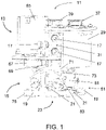
- a blow head 11 of a blow labeler according to the invention for applying labels to packaging is shown.
- the bubble labeller is part of a price labeling system for the automatic weighing and labeling of packaging.
- the price labeling system includes a transport device including a weighing belt to weigh the packaging and guide it past the bubbler labeller.
- the blow head 11 comprises a base platform 13 and a holding platform 15.
- the base platform 13 comprises an air connection device with a compressed air connection 17 (in 1 center left) and a first suction air connection 17 (in 1 top right) and a second suction air connection 17 (in 1 bottom right).
- the compressed air connection 17 is connected to a compressed air generator, and the two suction air connections 17 are connected to a suction air generator or vacuum generator, with the two suction air connections being able to be acted upon independently of one another with suction air or vacuum.
- a label contact surface 23 is formed on the underside of the holding platform, on which the labels can first be held using suction air and then blown off onto a package using compressed air.
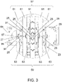
- blow-off openings 25 in fluid connection with the compressed air connection 17 and a large number of suction openings 27 in fluid connection with the two suction air connections 17 are provided in the label contact surface 23, as shown in FIG 3 is evident.
- All vent openings 25 are provided with a reference number.
- only some of the suction openings 27 are provided with a reference number.
- the effective area of the suction openings 27 is enlarged by grooves 95 and circular indentations 97 formed in the label contact surface 23 . No other vent or intake openings are provided.
- the holding platform 15 can be rotated on the base platform 13 stored. This allows the labels to be rotated relative to the packages.
- the base platform 13 has a drive with an electric motor 29 .
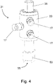
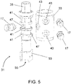
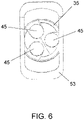
- the air connection device has a multi-channel rotary feedthrough 31 ( cf. the Figures 4 to 6 ).
- the rotary feedthrough 31 includes a stationary outer cylinder 33 and a rotatable inner cylinder 35, at the lower end of which the holding platform 15 is attached. At its upper end, the inner cylinder 35 is coupled to a driven pulley 39 which belongs to a toothed belt drive connected downstream of the electric motor 29 , the drive pulley 37 of which is driven by the motor shaft of the electric motor 29 .
- the belt of the toothed belt drive is not shown so that the other components can be seen better.
- the annular channels 41 are each connected in the radial direction via an associated opening 43 formed in the outer cylinder 33 to one of the three connections 17 and in the axial direction via an associated opening 47 formed in the inner cylinder 35, only two of which are visible one of the three channels 45 fluidly connected.
- the channels 45 are adjacent to each other and extend to the lower end of the inner cylinder 35 . Due to this design of the rotary feedthrough 31, the holding platform 15 can be rotated in both directions of rotation and indefinitely, ie without a stop.
- the holding platform 15 comprises an air connection piece 49 protruding in the direction of the base platform 13 (cf. 7 ), which forms a common interface of a compressed air and suction air line system 51 of the holding platform 15 to the rotary feedthrough 31.
- the inner cylinder 35 has an integrally formed coupling section 53 with a receptacle 55 designed in the opposite way to the air connection piece 49, which fits over the air connection piece 49 and, when the inner cylinder 35 rotates, takes the air connection piece 49 with it, so that the holding platform 15 is rotated accordingly .
- the channels 45 dip into receiving openings 89 formed in the air connection piece 49, from which the compressed air and suction air line system 51 extends to the blow-off and suction openings 25, 27.
- the compressed air and suction air line system 51 is designed in such a way that the lines assigned to the compressed air channel 45 , the lines assigned to the first suction air channel 45 and the lines assigned to the second suction air channel 45 run separately from one another.
- the label contact surface 23 is divided into a first contact area 57 and a second contact area 59, with the second contact area 59 being linearly displaceable relative to the first contact area 57 in the plane of the label contact surface 23, as explained in more detail below, in order to accommodate a second contact area System area 59 held label to move linearly.
- This allows the position of the labels on the packaging to be adjusted.
- the labels can be picked up by the label feed device through the displaceable second contact area 59 .
- Both the first contact area 57 and the second contact area 59 of the label contact surface 23 are each formed by a plurality of contact strips 61, 63. All contact strips 61, 63 are rectified, with the contact strips 61, 63 of the first and second contact areas 57, 59 alternating next to one another are arranged. How out 3 As can be seen, the contact strips 63 of the second contact area 59 are shorter than the contact strips 61 of the first contact area 57. In the first contact area 57 both suction openings 27 and blow-off openings 25 are formed, in the second contact area 59 only suction openings 27 are formed.
- the suction openings 27 of the first contact area 57 are connected to the first suction air connection 17 and the suction openings 27 of the second contact area 59 are connected to the second suction air connection 17 .
- the label can then be blown off through the blow-off openings 25 of the first contact area 57 .
- the transfer of the label from the second contact area 59 to the first contact area 57 makes it possible for the second contact area 59 to be moved back into the transfer position in order to pick up the next label while the holding platform 15 is still being rotated into the correct orientation for the current label will.
- the base platform 13 has a further drive with a further electric motor 65 .
- the further electric motor 65 is followed by a further toothed belt drive with a further drive pulley 67 and a further driven pulley 69 which is mounted on the rotatable inner cylinder 35 via a ball bearing.
- the belt of the other toothed belt drive is not shown for the sake of better visibility of the other components, and the other drive belt pulley 67 is toothed, contrary to the illustration.
- a bevel gear with a ring gear 71 and a pinion 73 is in turn connected downstream of the further toothed belt drive.
- the ring gear 71 is non-rotatably connected to the further output pulley 69 and slide-mounted on the rotatable inner cylinder 35, and the pinion 73 and a drive shaft 77 non-rotatably connected to the pinion 73 are each rotatably mounted on a base body 75 of the holding platform 15.
- the first contact area 57 is formed on the underside of the base body 75 .
- the compressed air and suction air line system 51 is arranged partially as tubes 19 integrated in the base body 75 of the holding platform 15 and partially as tubes 19 arranged on the top side of the base body 75 Pipe pieces 21 formed.
- the base body 75 has two retaining brackets 79 protruding in the direction of the base platform 13, on which a carriage arrangement is supported, which can be driven by the drive shaft 77, the second contact area 59 being formed on the underside of the carriage arrangement.
- the carriage arrangement is formed by two carriages 81 which can be displaced in parallel and in the same direction as one another. Each of the two carriages 81 carries two of the contact strips 63 of the second contact area 59.
- the two carriages 81 are each designed as a spindle nut and are each threaded onto a threaded spindle 83 .
- the two threaded spindles 83 are driven by the drive shaft 77 via a multi-drive belt drive 85 .
- a rotation of the two threaded spindles 83 leads to a displacement of the two carriages 81 and thus of the second contact area 59.
- the two carriages 81 are each guided along two guide rods 87, which are supported by the two retaining brackets 79.
- the compressed air and suction air line system 51 has an outlet 91 which branches off laterally from the air connection piece 49 and which has a T-shaped outlet (not shown). branched pipeline hose is connected to a respective inlet 93 of the two carriages 81 .
- the second contact area 59 would also be automatically displaced when the holding platform 15 rotates. This is prevented in that the further electric motor 65 is controlled in such a way that a displacement of the second contact area 59 caused by a rotation of the inner cylinder 35 is compensated for. If the holding platform 15 is to be rotated and the second contact area 59 is to be displaced at the same time, this is taken into account accordingly.
Landscapes
- Engineering & Computer Science (AREA)
- Mechanical Engineering (AREA)
- Labeling Devices (AREA)
Priority Applications (3)
| Application Number | Priority Date | Filing Date | Title |
|---|---|---|---|
| EP23178314.3A EP4234420A3 (fr) | 2021-06-16 | 2021-06-16 | Étiqueteuse par soufflage |
| EP21179819.4A EP4105134A1 (fr) | 2021-06-16 | 2021-06-16 | Étiqueteuse par soufflage |
| US17/839,204 US12122552B2 (en) | 2021-06-16 | 2022-06-13 | Blow labeler |
Applications Claiming Priority (1)
| Application Number | Priority Date | Filing Date | Title |
|---|---|---|---|
| EP21179819.4A EP4105134A1 (fr) | 2021-06-16 | 2021-06-16 | Étiqueteuse par soufflage |
Related Child Applications (1)
| Application Number | Title | Priority Date | Filing Date |
|---|---|---|---|
| EP23178314.3A Division EP4234420A3 (fr) | 2021-06-16 | 2021-06-16 | Étiqueteuse par soufflage |
Publications (1)
| Publication Number | Publication Date |
|---|---|
| EP4105134A1 true EP4105134A1 (fr) | 2022-12-21 |
Family
ID=76641589
Family Applications (2)
| Application Number | Title | Priority Date | Filing Date |
|---|---|---|---|
| EP21179819.4A Pending EP4105134A1 (fr) | 2021-06-16 | 2021-06-16 | Étiqueteuse par soufflage |
| EP23178314.3A Pending EP4234420A3 (fr) | 2021-06-16 | 2021-06-16 | Étiqueteuse par soufflage |
Family Applications After (1)
| Application Number | Title | Priority Date | Filing Date |
|---|---|---|---|
| EP23178314.3A Pending EP4234420A3 (fr) | 2021-06-16 | 2021-06-16 | Étiqueteuse par soufflage |
Country Status (2)
| Country | Link |
|---|---|
| US (1) | US12122552B2 (fr) |
| EP (2) | EP4105134A1 (fr) |
Citations (6)
| Publication number | Priority date | Publication date | Assignee | Title |
|---|---|---|---|---|
| US4612079A (en) * | 1984-07-25 | 1986-09-16 | Label-Aire, Inc. | Label applicator with pivotable labeling head |
| US4707211A (en) * | 1986-02-10 | 1987-11-17 | Ricoh Electronics, Inc. | Linerless thermal label printer and applicator |
| US5865918A (en) * | 1991-10-07 | 1999-02-02 | Pti, Inc. | Label applicator |
| DE102015106647A1 (de) | 2015-04-29 | 2016-11-03 | Espera-Werke Gmbh | Vorrichtung zum Etikettieren von einzelnen Produkten |
| EP3271254B1 (fr) * | 2015-11-06 | 2018-09-12 | Espera-Werke GmbH | Dispositif et procede d'etiquetage des emballages individuels |
| WO2020116575A1 (fr) * | 2018-12-07 | 2020-06-11 | 株式会社フジシールインターナショナル | Tête de fixation d'étiquette et dispositif de fixation d'étiquette |
Family Cites Families (4)
| Publication number | Priority date | Publication date | Assignee | Title |
|---|---|---|---|---|
| DE19545191A1 (de) * | 1995-12-04 | 1997-06-05 | Siemens Nixdorf Inf Syst | Vorrichtung zum Bereitstellen und Applizieren von Etiketten und Verfahren zum Betrieb dieser Vorrichtung |
| DE102009041470A1 (de) | 2009-09-14 | 2011-03-24 | Bizerba Gmbh & Co Kg | Roboter mit Delta-Kinematik |
| DE102011012919A1 (de) | 2011-03-03 | 2012-09-06 | Bizerba Gmbh & Co. Kg | Etikettiervorrichtung |
| US9802728B1 (en) * | 2014-03-26 | 2017-10-31 | Amazon Technologies, Inc. | Rotatable tamp head and automated dimension determination |
-
2021
- 2021-06-16 EP EP21179819.4A patent/EP4105134A1/fr active Pending
- 2021-06-16 EP EP23178314.3A patent/EP4234420A3/fr active Pending
-
2022
- 2022-06-13 US US17/839,204 patent/US12122552B2/en active Active
Patent Citations (6)
| Publication number | Priority date | Publication date | Assignee | Title |
|---|---|---|---|---|
| US4612079A (en) * | 1984-07-25 | 1986-09-16 | Label-Aire, Inc. | Label applicator with pivotable labeling head |
| US4707211A (en) * | 1986-02-10 | 1987-11-17 | Ricoh Electronics, Inc. | Linerless thermal label printer and applicator |
| US5865918A (en) * | 1991-10-07 | 1999-02-02 | Pti, Inc. | Label applicator |
| DE102015106647A1 (de) | 2015-04-29 | 2016-11-03 | Espera-Werke Gmbh | Vorrichtung zum Etikettieren von einzelnen Produkten |
| EP3271254B1 (fr) * | 2015-11-06 | 2018-09-12 | Espera-Werke GmbH | Dispositif et procede d'etiquetage des emballages individuels |
| WO2020116575A1 (fr) * | 2018-12-07 | 2020-06-11 | 株式会社フジシールインターナショナル | Tête de fixation d'étiquette et dispositif de fixation d'étiquette |
Also Published As
| Publication number | Publication date |
|---|---|
| EP4234420A3 (fr) | 2023-10-18 |
| US20220402641A1 (en) | 2022-12-22 |
| US12122552B2 (en) | 2024-10-22 |
| EP4234420A2 (fr) | 2023-08-30 |
Similar Documents
| Publication | Publication Date | Title |
|---|---|---|
| EP1561690B1 (fr) | Machine d'étiquetage | |
| EP2616346B1 (fr) | Procédé et dispositif d'étiquetage de bouteilles | |
| EP3676186B1 (fr) | Dispositif à porte-plaque à changement rapide et came de guidage coulissante | |
| DE102020206858A1 (de) | Segmentierter Vakuumtransferzylinder | |
| DE4201289C2 (de) | Vorrichtung zur Handhabung von Werkstücken | |
| DE102013013684A1 (de) | Fördereinheit und Fördersystem mit solchen Fördereinheiten | |
| EP3594155B1 (fr) | Margeur pour empilement des supports plats et procédé de fonctionnement du margeur | |
| DE102014108093A1 (de) | Ausstattungsmaschine mit Selbstklebeetikettierung | |
| EP0422425B1 (fr) | Poste de lissage pour presser des feuilles d'habillage posées sur la tête et sur le goulot de bouteilles | |
| DE102015103654B4 (de) | Etikettiervorrichtung für Behälter | |
| EP4105134A1 (fr) | Étiqueteuse par soufflage | |
| DE102008038144A1 (de) | Etikettiermaschine | |
| EP2186735B1 (fr) | Dispositif d'étiquetage | |
| DE10361204B4 (de) | Vorrichtung zur axialen Einstellung von Bremsstationen | |
| DE102007009240A1 (de) | Vorrichtung zum Transport beliebiger Teile | |
| DE102013206667A1 (de) | Behälterbehandlungsmaschine und Tischplatten für Behälterbehandlungsmaschinen | |
| EP0623457B1 (fr) | Magasin pour boîtes pliantes dans une machine d'emballage avec un conduit de magasin réglable | |
| DE29904552U1 (de) | Vorrichtung zum Etikettieren von Flaschen mit einem Etikettieraggregat | |
| EP0296407B1 (fr) | Dispositif pour déplacer axialement les supports des paliers de cylindres | |
| DE20310030U1 (de) | Fahrbarer Modulträger | |
| EP0522275B1 (fr) | Table d'alimentation pour machine à imprimer des feuilles | |
| DE3435681C2 (fr) | ||
| DE102023127472A1 (de) | Vorrichtung zum Drehen mindestens eines Behälters, Behandlungsmaschine und Anlage | |
| EP0376134B1 (fr) | Support de poste d'étiquetage équipé avec au moins un secteur de transfert d'étiquettes | |
| DE102023123674A1 (de) | Vorrichtung zum Führen von Behältern, Transportsystem und Behälterbehandlungsmaschine umfassend die Vorrichtung |
Legal Events
| Date | Code | Title | Description |
|---|---|---|---|
| PUAI | Public reference made under article 153(3) epc to a published international application that has entered the european phase |
Free format text: ORIGINAL CODE: 0009012 |
|
| STAA | Information on the status of an ep patent application or granted ep patent |
Free format text: STATUS: THE APPLICATION HAS BEEN PUBLISHED |
|
| AK | Designated contracting states |
Kind code of ref document: A1 Designated state(s): AL AT BE BG CH CY CZ DE DK EE ES FI FR GB GR HR HU IE IS IT LI LT LU LV MC MK MT NL NO PL PT RO RS SE SI SK SM TR |
|
| STAA | Information on the status of an ep patent application or granted ep patent |
Free format text: STATUS: REQUEST FOR EXAMINATION WAS MADE |
|
| 17P | Request for examination filed |
Effective date: 20230609 |
|
| RBV | Designated contracting states (corrected) |
Designated state(s): AL AT BE BG CH CY CZ DE DK EE ES FI FR GB GR HR HU IE IS IT LI LT LU LV MC MK MT NL NO PL PT RO RS SE SI SK SM TR |
|
| STAA | Information on the status of an ep patent application or granted ep patent |
Free format text: STATUS: EXAMINATION IS IN PROGRESS |
|
| 17Q | First examination report despatched |
Effective date: 20260107 |