EP4105454A1 - Ensemble carénage de turbine avec fixation de carénage à broches avant et arrière - Google Patents
Ensemble carénage de turbine avec fixation de carénage à broches avant et arrière Download PDFInfo
- Publication number
- EP4105454A1 EP4105454A1 EP22169266.8A EP22169266A EP4105454A1 EP 4105454 A1 EP4105454 A1 EP 4105454A1 EP 22169266 A EP22169266 A EP 22169266A EP 4105454 A1 EP4105454 A1 EP 4105454A1
- Authority
- EP
- European Patent Office
- Prior art keywords
- pin
- aft
- split
- support wall
- axially
- Prior art date
- Legal status (The legal status is an assumption and is not a legal conclusion. Google has not performed a legal analysis and makes no representation as to the accuracy of the status listed.)
- Pending
Links
- 238000009434 installation Methods 0.000 claims description 120
- 238000000034 method Methods 0.000 claims description 21
- 230000004323 axial length Effects 0.000 claims description 16
- 230000013011 mating Effects 0.000 claims description 12
- 230000008878 coupling Effects 0.000 claims description 5
- 238000010168 coupling process Methods 0.000 claims description 5
- 238000005859 coupling reaction Methods 0.000 claims description 5
- 239000000463 material Substances 0.000 claims description 5
- 239000011153 ceramic matrix composite Substances 0.000 claims description 4
- 239000007769 metal material Substances 0.000 claims description 3
- 230000000712 assembly Effects 0.000 description 10
- 238000000429 assembly Methods 0.000 description 10
- 238000002485 combustion reaction Methods 0.000 description 7
- 230000003068 static effect Effects 0.000 description 4
- 239000000446 fuel Substances 0.000 description 3
- 239000003292 glue Substances 0.000 description 3
- 239000000853 adhesive Substances 0.000 description 1
- 230000001070 adhesive effect Effects 0.000 description 1
- 229910045601 alloy Inorganic materials 0.000 description 1
- 239000000956 alloy Substances 0.000 description 1
- 239000000919 ceramic Substances 0.000 description 1
- 230000008602 contraction Effects 0.000 description 1
- 230000007423 decrease Effects 0.000 description 1
- 238000004519 manufacturing process Methods 0.000 description 1
- 239000002184 metal Substances 0.000 description 1
- 229910052751 metal Inorganic materials 0.000 description 1
- 150000002739 metals Chemical class 0.000 description 1
- 238000012986 modification Methods 0.000 description 1
- 230000004048 modification Effects 0.000 description 1
- 230000001737 promoting effect Effects 0.000 description 1
- 229910000601 superalloy Inorganic materials 0.000 description 1
Images


Classifications
-
- F—MECHANICAL ENGINEERING; LIGHTING; HEATING; WEAPONS; BLASTING
- F01—MACHINES OR ENGINES IN GENERAL; ENGINE PLANTS IN GENERAL; STEAM ENGINES
- F01D—NON-POSITIVE DISPLACEMENT MACHINES OR ENGINES, e.g. STEAM TURBINES
- F01D25/00—Component parts, details, or accessories, not provided for in, or of interest apart from, other groups
- F01D25/24—Casings; Casing parts, e.g. diaphragms, casing fastenings
- F01D25/246—Fastening of diaphragms or stator-rings
-
- F—MECHANICAL ENGINEERING; LIGHTING; HEATING; WEAPONS; BLASTING
- F01—MACHINES OR ENGINES IN GENERAL; ENGINE PLANTS IN GENERAL; STEAM ENGINES
- F01D—NON-POSITIVE DISPLACEMENT MACHINES OR ENGINES, e.g. STEAM TURBINES
- F01D11/00—Preventing or minimising internal leakage of working-fluid, e.g. between stages
- F01D11/08—Preventing or minimising internal leakage of working-fluid, e.g. between stages for sealing space between rotor blade tips and stator
-
- F—MECHANICAL ENGINEERING; LIGHTING; HEATING; WEAPONS; BLASTING
- F05—INDEXING SCHEMES RELATING TO ENGINES OR PUMPS IN VARIOUS SUBCLASSES OF CLASSES F01-F04
- F05D—INDEXING SCHEME FOR ASPECTS RELATING TO NON-POSITIVE-DISPLACEMENT MACHINES OR ENGINES, GAS-TURBINES OR JET-PROPULSION PLANTS
- F05D2220/00—Application
- F05D2220/30—Application in turbines
- F05D2220/32—Application in turbines in gas turbines
- F05D2220/323—Application in turbines in gas turbines for aircraft propulsion, e.g. jet engines
-
- F—MECHANICAL ENGINEERING; LIGHTING; HEATING; WEAPONS; BLASTING
- F05—INDEXING SCHEMES RELATING TO ENGINES OR PUMPS IN VARIOUS SUBCLASSES OF CLASSES F01-F04
- F05D—INDEXING SCHEME FOR ASPECTS RELATING TO NON-POSITIVE-DISPLACEMENT MACHINES OR ENGINES, GAS-TURBINES OR JET-PROPULSION PLANTS
- F05D2230/00—Manufacture
- F05D2230/50—Building or constructing in particular ways
- F05D2230/51—Building or constructing in particular ways in a modular way, e.g. using several identical or complementary parts or features
-
- F—MECHANICAL ENGINEERING; LIGHTING; HEATING; WEAPONS; BLASTING
- F05—INDEXING SCHEMES RELATING TO ENGINES OR PUMPS IN VARIOUS SUBCLASSES OF CLASSES F01-F04
- F05D—INDEXING SCHEME FOR ASPECTS RELATING TO NON-POSITIVE-DISPLACEMENT MACHINES OR ENGINES, GAS-TURBINES OR JET-PROPULSION PLANTS
- F05D2230/00—Manufacture
- F05D2230/60—Assembly methods
- F05D2230/64—Assembly methods using positioning or alignment devices for aligning or centring, e.g. pins
- F05D2230/642—Assembly methods using positioning or alignment devices for aligning or centring, e.g. pins using maintaining alignment while permitting differential dilatation
-
- F—MECHANICAL ENGINEERING; LIGHTING; HEATING; WEAPONS; BLASTING
- F05—INDEXING SCHEMES RELATING TO ENGINES OR PUMPS IN VARIOUS SUBCLASSES OF CLASSES F01-F04
- F05D—INDEXING SCHEME FOR ASPECTS RELATING TO NON-POSITIVE-DISPLACEMENT MACHINES OR ENGINES, GAS-TURBINES OR JET-PROPULSION PLANTS
- F05D2240/00—Components
- F05D2240/10—Stators
- F05D2240/11—Shroud seal segments
-
- F—MECHANICAL ENGINEERING; LIGHTING; HEATING; WEAPONS; BLASTING
- F05—INDEXING SCHEMES RELATING TO ENGINES OR PUMPS IN VARIOUS SUBCLASSES OF CLASSES F01-F04
- F05D—INDEXING SCHEME FOR ASPECTS RELATING TO NON-POSITIVE-DISPLACEMENT MACHINES OR ENGINES, GAS-TURBINES OR JET-PROPULSION PLANTS
- F05D2260/00—Function
- F05D2260/30—Retaining components in desired mutual position
- F05D2260/31—Retaining bolts or nuts
- F05D2260/311—Retaining bolts or nuts of the frangible or shear type
-
- F—MECHANICAL ENGINEERING; LIGHTING; HEATING; WEAPONS; BLASTING
- F05—INDEXING SCHEMES RELATING TO ENGINES OR PUMPS IN VARIOUS SUBCLASSES OF CLASSES F01-F04
- F05D—INDEXING SCHEME FOR ASPECTS RELATING TO NON-POSITIVE-DISPLACEMENT MACHINES OR ENGINES, GAS-TURBINES OR JET-PROPULSION PLANTS
- F05D2260/00—Function
- F05D2260/30—Retaining components in desired mutual position
- F05D2260/36—Retaining components in desired mutual position by a form fit connection, e.g. by interlocking
-
- F—MECHANICAL ENGINEERING; LIGHTING; HEATING; WEAPONS; BLASTING
- F05—INDEXING SCHEMES RELATING TO ENGINES OR PUMPS IN VARIOUS SUBCLASSES OF CLASSES F01-F04
- F05D—INDEXING SCHEME FOR ASPECTS RELATING TO NON-POSITIVE-DISPLACEMENT MACHINES OR ENGINES, GAS-TURBINES OR JET-PROPULSION PLANTS
- F05D2300/00—Materials; Properties thereof
- F05D2300/60—Properties or characteristics given to material by treatment or manufacturing
- F05D2300/603—Composites; e.g. fibre-reinforced
- F05D2300/6033—Ceramic matrix composites [CMC]
-
- Y—GENERAL TAGGING OF NEW TECHNOLOGICAL DEVELOPMENTS; GENERAL TAGGING OF CROSS-SECTIONAL TECHNOLOGIES SPANNING OVER SEVERAL SECTIONS OF THE IPC; TECHNICAL SUBJECTS COVERED BY FORMER USPC CROSS-REFERENCE ART COLLECTIONS [XRACs] AND DIGESTS
- Y02—TECHNOLOGIES OR APPLICATIONS FOR MITIGATION OR ADAPTATION AGAINST CLIMATE CHANGE
- Y02T—CLIMATE CHANGE MITIGATION TECHNOLOGIES RELATED TO TRANSPORTATION
- Y02T50/00—Aeronautics or air transport
- Y02T50/60—Efficient propulsion technologies, e.g. for aircraft
Definitions
- Some shrouds positioned in the turbine may be exposed to high temperatures from products of the combustion reaction in the combustor.
- Such shrouds sometimes include components made from materials that have different coefficients of thermal expansion. Due to the differing coefficients of thermal expansion, the components of some turbine shrouds expand at different rates when exposed to high temperatures. In some examples, coupling these components with traditional fasteners may not allow for the differing levels of expansion and contraction during operation of the gas turbine engine.
- the present disclosure may comprise one or more of the following features and combinations thereof.
- the seal segment may be shaped to include a runner, a forward mount flange, and an aft mount flange.
- the runner may extend circumferentially partway around the axis to define the gas path boundary of the shroud assembly.
- the forward mount flange and the aft mount flange may each extend radially outward from the runner.
- the forward mount flange may be arranged between the forward support wall and the central support wall of the carrier.
- the aft mount flange may extend radially outward from the runner and may be arranged between the aft support wall and the central support wall of the carrier.
- the central support wall may include an aft support plate.
- the aft support plate may be formed to include aft support holes.
- the aft support holes may receive a portion of the aft pin included in the first split-pin assembly and a portion of the aft pin included in the second split-pin assembly.
- a turbine shroud assembly adapted for use with a gas turbine engine may include a carrier, a seal segment, and a mount assembly.
- the mount assembly may couple the seal segment to the carrier.
- the seal segment may be coupled to the carrier with the second split-pin fastener by inserting the aft pin of the second split-pin fastener through the aft mount flange of the seal segment into both the aft and central support walls of the carrier so that the aft pin of the second split-pin fastener is circumferentially aligned with and aft of the forward pin of the second split-pin fastener.
- the forward pin 42, 46 is in direct confronting relation with the aft pin 44, 48, while remaining separate from the aft pin 44, 48.
- the pins 42, 44, 46, 48 allow for independent loading during use in the gas turbine engine 10.
- the independent loading of the pins 42, 44, 46, 48 accommodates manufacturing tolerances and increases the number of loading points for the seal segment 26. The increased number of loading points decreases localized stresses in the assembly 22.
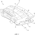
- the turbine shroud assembly 20 is annular and non-segmented to extend fully around the central axis 11 and surround the turbine wheel assembly 13. In yet other embodiments, certain components of the turbine shroud assembly 20 are segmented while other components are annular and non-segmented.
- any of the holes 64, 66, 68A, 68B may be oval shaped. In other embodiments, any of the holes 64, 66, 68A, 68B may be racetrack shaped. In the illustrative embodiment, the holes 64, 66, 68A, 68B are circular in shape.
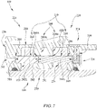
- the mount assembly 228 includes a first split-pin fastener 230 and a second split-pin fastener (not shown) that cooperate to couple the mount flanges 272, 274 of the seal segment 226 with the support walls 256, 258, 260 of the carrier 224 to support the seal segment 226 radially relative to the axis 11 of the gas turbine engine 10.
- the second pin 244 has a second axial length 244L that is greater than the first axial length 242L of the forward pin 242 as shown in Figs. 7 and 8 .
- the second axial length 244L of the aft pin 244 fills the space between the end 281 of the forward pin 242 and the aft support wall 258 when assembled.
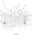
- Each of the split-pin fasteners 330 is made up of a forward pin 342 and an aft pin 344 as shown in Fig. 10 .
- the forward and aft pins 342, 344 each extend axially through the seal segment 326 into the carrier 324.
- the aft pin 344 is circumferentially aligned with and aft of the forward pin 342.
- the forward pin 342 is in direct confronting relation with the aft pin 344 while remaining separate from the aft pin 344.
- the forward pin 342 extends axially through the forward mount flange 372 of the seal segment 326 into the forward support wall 356 and the central support wall 360 of the carrier 324.
- One end 380 of the forward pin 342 extends into an axially-extending blind support hole 364 of the forward support wall 356, while the other end 381 of the forward pin 342 extends into a forward support hole 368A formed in the central support wall 360 and abuts the aft pin 344.
- the connector 649 allows the forward and aft pins 642, 644, 646, 648 of each split-pin fasteners 630, 632 to be inserted simultaneously.
- a corresponding retainer plug 634, 636 may be inserted into the installation aperture 666.
- a corresponding retainer pin 638, 640 may then inserted radially into the carrier 624 to block removal of the corresponding retainer plug 634, 636.
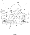
- the connector 749 is configured to separate so that the forward and aft pins 742, 744 become separate independent pins.
- the connector 749 aids installation of the first and second split-pin fasteners 730 but the connector 749 is configured to burn away during use of the turbine shroud assembly 722 of the gas turbine engine 10 to allow for independent loading of the forward and aft pins 742, 744.
- the connector 749 an adhesive, such as glue, that is configured to burn away during use of the gas turbine engine 10.
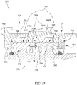
- Each hook 784 includes an axially-extending portion 785A, 785B and a radially-extending portion 787A, 787B as shown in Figs. 18 and 19 .
- the axially-extending portion 785A, 785B extends axially from the corresponding end 781, 782 of the respective pin 742, 744.
- the radially-extending portion 787A, 787B extends radially inward from the axially-extending portion 785A, 785B to define a channel 789A, 789B and forms the hook shape.
- the split-pin fasteners 730 may then be removed out through the installation aperture 766.
- the removal of the aft pin 744 causes the removal of the forward pin 742.
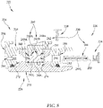
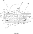
- the forward blind support holes 868A extend axially into a forward surface 867 of the central support wall 860, while the aft blind support holes 868B extend axially into an aft surface 869 as shown in Fig. 20 .
- the blind support holes 868A, 868B are aligned with the corresponding axially-extending installation apertures 864, 866 to receive the forward and aft pins 842, 844.
- the mount assembly 828 further includes retainer plugs 834, 835 as shown in Fig. 20 .
- the retainer plugs 834, 835 are configured to block removal of the forward and aft pins 842, 844 out through the installation apertures 864, 866.
- the retainer plugs 834, 835 extend into the carrier 824 and engage the corresponding pin 842, 844 to block removal of the forward and aft pins 842, 844.
Landscapes
- Engineering & Computer Science (AREA)
- Mechanical Engineering (AREA)
- General Engineering & Computer Science (AREA)
- Structures Of Non-Positive Displacement Pumps (AREA)
- Turbine Rotor Nozzle Sealing (AREA)
Applications Claiming Priority (1)
| Application Number | Priority Date | Filing Date | Title |
|---|---|---|---|
| US17/351,736 US11441441B1 (en) | 2021-06-18 | 2021-06-18 | Turbine shroud with split pin mounted ceramic matrix composite blade track |
Publications (1)
| Publication Number | Publication Date |
|---|---|
| EP4105454A1 true EP4105454A1 (fr) | 2022-12-21 |
Family
ID=81346234
Family Applications (1)
| Application Number | Title | Priority Date | Filing Date |
|---|---|---|---|
| EP22169266.8A Pending EP4105454A1 (fr) | 2021-06-18 | 2022-04-21 | Ensemble carénage de turbine avec fixation de carénage à broches avant et arrière |
Country Status (2)
| Country | Link |
|---|---|
| US (1) | US11441441B1 (fr) |
| EP (1) | EP4105454A1 (fr) |
Families Citing this family (20)
| Publication number | Priority date | Publication date | Assignee | Title |
|---|---|---|---|---|
| US12006875B1 (en) | 2023-04-07 | 2024-06-11 | Rtx Corporation | Fusible gearbox center guide support with frangible catcher pin systems and methods |
| US12044181B1 (en) * | 2023-04-07 | 2024-07-23 | Rtx Corporation | Fusible gearbox center guide support with catcher pin and anti-rotation pin systems and methods |
| US12196138B2 (en) | 2023-04-07 | 2025-01-14 | Rtx Corporation | Frangible gearbox center guide support systems and methods |
| US12209539B2 (en) | 2023-04-07 | 2025-01-28 | Rtx Corporation | Fusible gearbox support with catcher pin systems and methods |
| US12421862B2 (en) | 2023-12-04 | 2025-09-23 | Rolls-Royce Corporation | Turbine shroud assembly with angled cooling holes |
| US12152499B1 (en) | 2023-12-04 | 2024-11-26 | Rolls-Royce Corporation | Turbine shroud segments with strip seal assemblies having dampened ends |
| US12241376B1 (en) | 2023-12-04 | 2025-03-04 | Rolls-Royce Corporation | Locating plate for use with turbine shroud assemblies |
| US12286906B1 (en) | 2023-12-04 | 2025-04-29 | Rolls-Royce Corporation | Locating plate for use with turbine shroud assemblies |
| US12188365B1 (en) | 2023-12-04 | 2025-01-07 | Rolls-Royce Corporation | Method and apparatus for ceramic matrix composite turbine shroud assembly |
| US12286885B1 (en) | 2023-12-04 | 2025-04-29 | Rolls-Royce Corporation | Turbine assembly with confronting vane and turbine shroud segment |
| US12158072B1 (en) | 2023-12-04 | 2024-12-03 | Rolls-Royce Corporation | Turbine shroud segments with damping strip seals |
| US12421870B1 (en) | 2024-04-30 | 2025-09-23 | Rolls-Royce Corporation | Pin mounted ceramic matrix composite heat shields with impingement cooling |
| US12305525B1 (en) * | 2024-05-30 | 2025-05-20 | Rolls-Royce Corporation | Turbine shroud assemblies with rod seal and strip seals |
| US12258880B1 (en) | 2024-05-30 | 2025-03-25 | Rolls-Royce Corporation | Turbine shroud assemblies with inter-segment strip seal |
| US12416241B1 (en) | 2024-05-30 | 2025-09-16 | Rolls-Royce Corporation | Turbine shroud assemblies with strip seals |
| US12215593B1 (en) | 2024-05-30 | 2025-02-04 | Rolls-Royce Corporation | Turbine shroud assembly with inter-segment damping |
| US12352176B1 (en) | 2024-05-31 | 2025-07-08 | Rolls-Royce Corporation | Turbine shroud assemblies with channels for buffer cavity seal thermal management |
| US12410725B1 (en) | 2024-05-31 | 2025-09-09 | Rolls-Royce Corporation | Turbine shroud assemblies with air activated pistons for biasing buffer cavity seals |
| US12577881B2 (en) | 2024-05-31 | 2026-03-17 | Rolls-Royce Corporation | Turbine shroud assemblies with anti-migration seals |
| US12228044B1 (en) | 2024-06-26 | 2025-02-18 | Rolls-Royce Corporation | Turbine shroud system with ceramic matrix composite segments and dual inter-segment seals |
Citations (4)
| Publication number | Priority date | Publication date | Assignee | Title |
|---|---|---|---|---|
| US20100104426A1 (en) * | 2006-07-25 | 2010-04-29 | Siemens Power Generation, Inc. | Turbine engine ring seal |
| EP3043032A1 (fr) * | 2014-12-29 | 2016-07-13 | Rolls-Royce North American Technologies, Inc. | Ensemble de piste d'aube avec commande de jeu d'extrémité d'aube de turbine |
| EP3178799A1 (fr) * | 2015-12-09 | 2017-06-14 | General Electric Company | Compositions abradables et procédés pour enveloppe cmc |
| US20180195403A1 (en) * | 2017-01-12 | 2018-07-12 | General Electric Company | Aero loading shroud sealing |
Family Cites Families (41)
| Publication number | Priority date | Publication date | Assignee | Title |
|---|---|---|---|---|
| US3066911A (en) | 1959-05-12 | 1962-12-04 | Thompson Ramo Wooldridge Inc | Nozzle and turbine wheel shroud support |
| FR2576637B1 (fr) | 1985-01-30 | 1988-11-18 | Snecma | Anneau de turbine a gaz. |
| GB2260371B (en) | 1991-10-09 | 1994-11-09 | Rolls Royce Plc | Turbine engines |
| US5203673A (en) | 1992-01-21 | 1993-04-20 | Westinghouse Electric Corp. | Tip clearance control apparatus for a turbo-machine blade |
| US5405245A (en) | 1993-11-29 | 1995-04-11 | Solar Turbines Incorporated | Ceramic blade attachment system |
| US5459995A (en) | 1994-06-27 | 1995-10-24 | Solar Turbines Incorporated | Turbine nozzle attachment system |
| US7416362B2 (en) | 2002-08-16 | 2008-08-26 | Siemens Power Generation, Inc. | Multidirectionally compliant fastening system |
| US6877952B2 (en) | 2002-09-09 | 2005-04-12 | Florida Turbine Technologies, Inc | Passive clearance control |
| US6884026B2 (en) | 2002-09-30 | 2005-04-26 | General Electric Company | Turbine engine shroud assembly including axially floating shroud segment |
| US6821085B2 (en) * | 2002-09-30 | 2004-11-23 | General Electric Company | Turbine engine axially sealing assembly including an axially floating shroud, and assembly method |
| US7494317B2 (en) | 2005-06-23 | 2009-02-24 | Siemens Energy, Inc. | Ring seal attachment system |
| US7534086B2 (en) | 2006-05-05 | 2009-05-19 | Siemens Energy, Inc. | Multi-layer ring seal |
| US8944756B2 (en) | 2011-07-15 | 2015-02-03 | United Technologies Corporation | Blade outer air seal assembly |
| US9598975B2 (en) | 2013-03-14 | 2017-03-21 | Rolls-Royce Corporation | Blade track assembly with turbine tip clearance control |
| US9874104B2 (en) | 2015-02-27 | 2018-01-23 | General Electric Company | Method and system for a ceramic matrix composite shroud hanger assembly |
| FR3033826B1 (fr) | 2015-03-16 | 2018-11-23 | Safran Ceramics | Ensemble d'anneau de turbine comprenant une pluralite de secteurs d'anneau en materiau composite a matrice ceramique |
| FR3033825B1 (fr) | 2015-03-16 | 2018-09-07 | Safran Aircraft Engines | Ensemble d'anneau de turbine en materiau composite a matrice ceramique |
| US9863265B2 (en) | 2015-04-15 | 2018-01-09 | General Electric Company | Shroud assembly and shroud for gas turbine engine |
| FR3036432B1 (fr) | 2015-05-22 | 2019-04-19 | Safran Ceramics | Ensemble d'anneau de turbine avec maintien axial |
| US10215056B2 (en) | 2015-06-30 | 2019-02-26 | Rolls-Royce Corporation | Turbine shroud with movable attachment features |
| US10030541B2 (en) | 2015-07-01 | 2018-07-24 | Rolls-Royce North American Technologies Inc. | Turbine shroud with clamped flange attachment |
| US10301960B2 (en) | 2015-07-13 | 2019-05-28 | General Electric Company | Shroud assembly for gas turbine engine |
| FR3041993B1 (fr) | 2015-10-05 | 2019-06-21 | Safran Aircraft Engines | Ensemble d'anneau de turbine avec maintien axial |
| FR3045715B1 (fr) | 2015-12-18 | 2018-01-26 | Safran Aircraft Engines | Ensemble d'anneau de turbine avec maintien a froid et a chaud |
| FR3045716B1 (fr) | 2015-12-18 | 2018-01-26 | Safran Aircraft Engines | Ensemble d'anneau de turbine avec maintien elastique a froid |
| FR3048016B1 (fr) | 2016-02-18 | 2018-03-16 | Safran Ceramics | Secteur d'anneau de turbine avec barriere environnementale dopee par un element electriquement conducteur |
| FR3049003B1 (fr) | 2016-03-21 | 2018-04-06 | Safran Aircraft Engines | Ensemble d'anneau de turbine sans jeu de montage a froid |
| FR3055147B1 (fr) | 2016-08-19 | 2020-05-29 | Safran Aircraft Engines | Ensemble d'anneau de turbine |
| DE102017209682A1 (de) | 2017-06-08 | 2018-12-13 | MTU Aero Engines AG | Axial geteilter Turbomaschinen-Innenring |
| US10774008B2 (en) | 2017-09-21 | 2020-09-15 | General Electric Company | Ceramic matrix composite articles |
| US10619514B2 (en) | 2017-10-18 | 2020-04-14 | Rolls-Royce Corporation | Ceramic matrix composite assembly with compliant pin attachment features |
| FR3072720B1 (fr) | 2017-10-23 | 2019-09-27 | Safran Aircraft Engines | Carter pour turbomachine comprenant une portion centrale en saillie relativement a deux portions laterales dans une region de jonction |
| US10801350B2 (en) * | 2018-02-23 | 2020-10-13 | Rolls-Royce Corporation | Actively cooled engine assembly with ceramic matrix composite components |
| US10815810B2 (en) | 2019-01-10 | 2020-10-27 | Raytheon Technologies Corporation | BOAS assemblies with axial support pins |
| US11220930B2 (en) | 2019-12-03 | 2022-01-11 | Rolls-Royce Corporation | Assembly with pin-mounted ceramic matrix composite material components |
| US11066947B2 (en) | 2019-12-18 | 2021-07-20 | Rolls-Royce Corporation | Turbine shroud assembly with sealed pin mounting arrangement |
| US11073045B2 (en) | 2019-12-18 | 2021-07-27 | Rolls-Royce Corporation | Turbine shroud assembly with case captured seal segment carrier |
| US11174743B2 (en) * | 2019-12-20 | 2021-11-16 | Rolls-Royce Corporation | Turbine shroud assembly with multi-piece support for ceramic matrix composite material seal segments |
| US11215065B2 (en) * | 2020-04-24 | 2022-01-04 | Rolls-Royce Corporation | Turbine shroud assembly with ceramic matrix composite components having stress-reduced pin attachment |
| US11346237B1 (en) * | 2021-05-25 | 2022-05-31 | Rolls-Royce Corporation | Turbine shroud assembly with axially biased ceramic matrix composite shroud segment |
| US11319828B1 (en) * | 2021-06-18 | 2022-05-03 | Rolls-Royce Corporation | Turbine shroud assembly with separable pin attachment |
-
2021
- 2021-06-18 US US17/351,736 patent/US11441441B1/en active Active
-
2022
- 2022-04-21 EP EP22169266.8A patent/EP4105454A1/fr active Pending
Patent Citations (4)
| Publication number | Priority date | Publication date | Assignee | Title |
|---|---|---|---|---|
| US20100104426A1 (en) * | 2006-07-25 | 2010-04-29 | Siemens Power Generation, Inc. | Turbine engine ring seal |
| EP3043032A1 (fr) * | 2014-12-29 | 2016-07-13 | Rolls-Royce North American Technologies, Inc. | Ensemble de piste d'aube avec commande de jeu d'extrémité d'aube de turbine |
| EP3178799A1 (fr) * | 2015-12-09 | 2017-06-14 | General Electric Company | Compositions abradables et procédés pour enveloppe cmc |
| US20180195403A1 (en) * | 2017-01-12 | 2018-07-12 | General Electric Company | Aero loading shroud sealing |
Also Published As
| Publication number | Publication date |
|---|---|
| US11441441B1 (en) | 2022-09-13 |
Similar Documents
| Publication | Publication Date | Title |
|---|---|---|
| EP4105448B1 (fr) | Ensemble enveloppe de turbine à fixation de broche séparable | |
| EP4105454A1 (fr) | Ensemble carénage de turbine avec fixation de carénage à broches avant et arrière | |
| EP4105453A1 (fr) | Ensemble carénage de turbine avec fixation de carénage à broches avant et arrière | |
| US11773751B1 (en) | Ceramic matrix composite blade track segment with pin-locating threaded insert | |
| EP4095355A1 (fr) | Ensemble enveloppe de turbine avec tige sollicitée axialement et segment d'enveloppe | |
| US11466586B2 (en) | Turbine shroud assembly with sealed pin mounting arrangement | |
| US11840936B1 (en) | Ceramic matrix composite blade track segment with pin-locating shim kit | |
| US11732604B1 (en) | Ceramic matrix composite blade track segment with integrated cooling passages | |
| EP4095356A1 (fr) | Ensemble enveloppe de turbine comportant un segment d'enveloppe composite à matrice céramique décalé axialement | |
| US11713694B1 (en) | Ceramic matrix composite blade track segment with two-piece carrier | |
| US11629607B2 (en) | Turbine shroud assembly with radially and axially biased ceramic matrix composite shroud segments | |
| US11761351B2 (en) | Turbine shroud assembly with radially located ceramic matrix composite shroud segments | |
| EP4095352A1 (fr) | Ensemble enveloppe de turbine avec segments d'enveloppe composite à matrice céramique polarisés radialement | |
| US11326474B2 (en) | Turbine shroud assembly with pinned attachment supplements for ceramic matrix composite component mounting | |
| US11378012B2 (en) | Insert-mounted turbine assembly for a gas turbine engine | |
| US11885225B1 (en) | Turbine blade track with ceramic matrix composite segments having attachment flange draft angles | |
| US11959389B2 (en) | Turbine shroud segments with angular locating feature | |
| US20250179935A1 (en) | Turbine shroud assembly with pinned turbine shroud and vane with pin retainer | |
| US11187099B1 (en) | Turbine shroud with containment features | |
| US12146417B2 (en) | Turbine shroud with ceramic matrix composite blade track segments and method of assembly | |
| US12286885B1 (en) | Turbine assembly with confronting vane and turbine shroud segment | |
| US11746658B2 (en) | Turbine shroud with containment features | |
| US12215593B1 (en) | Turbine shroud assembly with inter-segment damping |
Legal Events
| Date | Code | Title | Description |
|---|---|---|---|
| PUAI | Public reference made under article 153(3) epc to a published international application that has entered the european phase |
Free format text: ORIGINAL CODE: 0009012 |
|
| STAA | Information on the status of an ep patent application or granted ep patent |
Free format text: STATUS: THE APPLICATION HAS BEEN PUBLISHED |
|
| AK | Designated contracting states |
Kind code of ref document: A1 Designated state(s): AL AT BE BG CH CY CZ DE DK EE ES FI FR GB GR HR HU IE IS IT LI LT LU LV MC MK MT NL NO PL PT RO RS SE SI SK SM TR |
|
| STAA | Information on the status of an ep patent application or granted ep patent |
Free format text: STATUS: REQUEST FOR EXAMINATION WAS MADE |
|
| 17P | Request for examination filed |
Effective date: 20230609 |
|
| RBV | Designated contracting states (corrected) |
Designated state(s): AL AT BE BG CH CY CZ DE DK EE ES FI FR GB GR HR HU IE IS IT LI LT LU LV MC MK MT NL NO PL PT RO RS SE SI SK SM TR |
|
| STAA | Information on the status of an ep patent application or granted ep patent |
Free format text: STATUS: EXAMINATION IS IN PROGRESS |
|
| 17Q | First examination report despatched |
Effective date: 20240604 |