EP4105461A1 - Gasturbinentriebwerk - Google Patents
Gasturbinentriebwerk Download PDFInfo
- Publication number
- EP4105461A1 EP4105461A1 EP21753566.5A EP21753566A EP4105461A1 EP 4105461 A1 EP4105461 A1 EP 4105461A1 EP 21753566 A EP21753566 A EP 21753566A EP 4105461 A1 EP4105461 A1 EP 4105461A1
- Authority
- EP
- European Patent Office
- Prior art keywords
- rear bearing
- housing
- bearing
- outer race
- gas turbine
- Prior art date
- Legal status (The legal status is an assumption and is not a legal conclusion. Google has not performed a legal analysis and makes no representation as to the accuracy of the status listed.)
- Granted
Links
Images


Classifications
-
- F—MECHANICAL ENGINEERING; LIGHTING; HEATING; WEAPONS; BLASTING
- F01—MACHINES OR ENGINES IN GENERAL; ENGINE PLANTS IN GENERAL; STEAM ENGINES
- F01D—NON-POSITIVE DISPLACEMENT MACHINES OR ENGINES, e.g. STEAM TURBINES
- F01D25/00—Component parts, details, or accessories, not provided for in, or of interest apart from, other groups
- F01D25/16—Arrangement of bearings; Supporting or mounting bearings in casings
- F01D25/162—Bearing supports
- F01D25/164—Flexible supports; Vibration damping means associated with the bearing
-
- F—MECHANICAL ENGINEERING; LIGHTING; HEATING; WEAPONS; BLASTING
- F02—COMBUSTION ENGINES; HOT-GAS OR COMBUSTION-PRODUCT ENGINE PLANTS
- F02C—GAS-TURBINE PLANTS; AIR INTAKES FOR JET-PROPULSION PLANTS; CONTROLLING FUEL SUPPLY IN AIR-BREATHING JET-PROPULSION PLANTS
- F02C7/00—Features, components parts, details or accessories, not provided for in, or of interest apart form groups F02C1/00 - F02C6/00; Air intakes for jet-propulsion plants
- F02C7/06—Arrangements of bearings; Lubricating
-
- F—MECHANICAL ENGINEERING; LIGHTING; HEATING; WEAPONS; BLASTING
- F01—MACHINES OR ENGINES IN GENERAL; ENGINE PLANTS IN GENERAL; STEAM ENGINES
- F01D—NON-POSITIVE DISPLACEMENT MACHINES OR ENGINES, e.g. STEAM TURBINES
- F01D25/00—Component parts, details, or accessories, not provided for in, or of interest apart from, other groups
- F01D25/16—Arrangement of bearings; Supporting or mounting bearings in casings
-
- F—MECHANICAL ENGINEERING; LIGHTING; HEATING; WEAPONS; BLASTING
- F01—MACHINES OR ENGINES IN GENERAL; ENGINE PLANTS IN GENERAL; STEAM ENGINES
- F01D—NON-POSITIVE DISPLACEMENT MACHINES OR ENGINES, e.g. STEAM TURBINES
- F01D25/00—Component parts, details, or accessories, not provided for in, or of interest apart from, other groups
- F01D25/18—Lubricating arrangements
-
- F—MECHANICAL ENGINEERING; LIGHTING; HEATING; WEAPONS; BLASTING
- F16—ENGINEERING ELEMENTS AND UNITS; GENERAL MEASURES FOR PRODUCING AND MAINTAINING EFFECTIVE FUNCTIONING OF MACHINES OR INSTALLATIONS; THERMAL INSULATION IN GENERAL
- F16C—SHAFTS; FLEXIBLE SHAFTS; ELEMENTS OR CRANKSHAFT MECHANISMS; ROTARY BODIES OTHER THAN GEARING ELEMENTS; BEARINGS
- F16C19/00—Bearings with rolling contact, for exclusively rotary movement
- F16C19/02—Bearings with rolling contact, for exclusively rotary movement with bearing balls essentially of the same size in one or more circular rows
-
- F—MECHANICAL ENGINEERING; LIGHTING; HEATING; WEAPONS; BLASTING
- F16—ENGINEERING ELEMENTS AND UNITS; GENERAL MEASURES FOR PRODUCING AND MAINTAINING EFFECTIVE FUNCTIONING OF MACHINES OR INSTALLATIONS; THERMAL INSULATION IN GENERAL
- F16C—SHAFTS; FLEXIBLE SHAFTS; ELEMENTS OR CRANKSHAFT MECHANISMS; ROTARY BODIES OTHER THAN GEARING ELEMENTS; BEARINGS
- F16C23/00—Bearings for exclusively rotary movement adjustable for aligning or positioning
- F16C23/06—Ball or roller bearings
- F16C23/08—Ball or roller bearings self-adjusting
-
- F—MECHANICAL ENGINEERING; LIGHTING; HEATING; WEAPONS; BLASTING
- F16—ENGINEERING ELEMENTS AND UNITS; GENERAL MEASURES FOR PRODUCING AND MAINTAINING EFFECTIVE FUNCTIONING OF MACHINES OR INSTALLATIONS; THERMAL INSULATION IN GENERAL
- F16C—SHAFTS; FLEXIBLE SHAFTS; ELEMENTS OR CRANKSHAFT MECHANISMS; ROTARY BODIES OTHER THAN GEARING ELEMENTS; BEARINGS
- F16C27/00—Elastic or yielding bearings or bearing supports, for exclusively rotary movement
- F16C27/04—Ball or roller bearings, e.g. with resilient rolling bodies
-
- F—MECHANICAL ENGINEERING; LIGHTING; HEATING; WEAPONS; BLASTING
- F16—ENGINEERING ELEMENTS AND UNITS; GENERAL MEASURES FOR PRODUCING AND MAINTAINING EFFECTIVE FUNCTIONING OF MACHINES OR INSTALLATIONS; THERMAL INSULATION IN GENERAL
- F16C—SHAFTS; FLEXIBLE SHAFTS; ELEMENTS OR CRANKSHAFT MECHANISMS; ROTARY BODIES OTHER THAN GEARING ELEMENTS; BEARINGS
- F16C33/00—Parts of bearings; Special methods for making bearings or parts thereof
- F16C33/30—Parts of ball or roller bearings
- F16C33/303—Parts of ball or roller bearings of hybrid bearings, e.g. rolling bearings with steel races and ceramic rolling elements
-
- F—MECHANICAL ENGINEERING; LIGHTING; HEATING; WEAPONS; BLASTING
- F16—ENGINEERING ELEMENTS AND UNITS; GENERAL MEASURES FOR PRODUCING AND MAINTAINING EFFECTIVE FUNCTIONING OF MACHINES OR INSTALLATIONS; THERMAL INSULATION IN GENERAL
- F16C—SHAFTS; FLEXIBLE SHAFTS; ELEMENTS OR CRANKSHAFT MECHANISMS; ROTARY BODIES OTHER THAN GEARING ELEMENTS; BEARINGS
- F16C35/00—Rigid support of bearing units; Housings, e.g. caps, covers
- F16C35/04—Rigid support of bearing units; Housings, e.g. caps, covers in the case of ball or roller bearings
- F16C35/042—Housings for rolling element bearings for rotary movement
-
- F—MECHANICAL ENGINEERING; LIGHTING; HEATING; WEAPONS; BLASTING
- F16—ENGINEERING ELEMENTS AND UNITS; GENERAL MEASURES FOR PRODUCING AND MAINTAINING EFFECTIVE FUNCTIONING OF MACHINES OR INSTALLATIONS; THERMAL INSULATION IN GENERAL
- F16C—SHAFTS; FLEXIBLE SHAFTS; ELEMENTS OR CRANKSHAFT MECHANISMS; ROTARY BODIES OTHER THAN GEARING ELEMENTS; BEARINGS
- F16C35/00—Rigid support of bearing units; Housings, e.g. caps, covers
- F16C35/04—Rigid support of bearing units; Housings, e.g. caps, covers in the case of ball or roller bearings
- F16C35/06—Mounting or dismounting of ball or roller bearings; Fixing them onto shaft or in housing
- F16C35/07—Fixing them on the shaft or housing with interposition of an element
- F16C35/077—Fixing them on the shaft or housing with interposition of an element between housing and outer race ring
-
- F—MECHANICAL ENGINEERING; LIGHTING; HEATING; WEAPONS; BLASTING
- F16—ENGINEERING ELEMENTS AND UNITS; GENERAL MEASURES FOR PRODUCING AND MAINTAINING EFFECTIVE FUNCTIONING OF MACHINES OR INSTALLATIONS; THERMAL INSULATION IN GENERAL
- F16N—LUBRICATING
- F16N7/00—Arrangements for supplying oil or unspecified lubricant from a stationary reservoir or the equivalent in or on the machine or member to be lubricated
- F16N7/30—Arrangements for supplying oil or unspecified lubricant from a stationary reservoir or the equivalent in or on the machine or member to be lubricated the oil being fed or carried along by another fluid
- F16N7/32—Mist lubrication
-
- F—MECHANICAL ENGINEERING; LIGHTING; HEATING; WEAPONS; BLASTING
- F16—ENGINEERING ELEMENTS AND UNITS; GENERAL MEASURES FOR PRODUCING AND MAINTAINING EFFECTIVE FUNCTIONING OF MACHINES OR INSTALLATIONS; THERMAL INSULATION IN GENERAL
- F16N—LUBRICATING
- F16N7/00—Arrangements for supplying oil or unspecified lubricant from a stationary reservoir or the equivalent in or on the machine or member to be lubricated
- F16N7/38—Arrangements for supplying oil or unspecified lubricant from a stationary reservoir or the equivalent in or on the machine or member to be lubricated with a separate pump; Central lubrication systems
-
- F—MECHANICAL ENGINEERING; LIGHTING; HEATING; WEAPONS; BLASTING
- F05—INDEXING SCHEMES RELATING TO ENGINES OR PUMPS IN VARIOUS SUBCLASSES OF CLASSES F01-F04
- F05B—INDEXING SCHEME RELATING TO WIND, SPRING, WEIGHT, INERTIA OR LIKE MOTORS, TO MACHINES OR ENGINES FOR LIQUIDS COVERED BY SUBCLASSES F03B, F03D AND F03G
- F05B2230/00—Manufacture
- F05B2230/60—Assembly methods
- F05B2230/604—Assembly methods using positioning or alignment devices for aligning or centering, e.g. pins
- F05B2230/606—Assembly methods using positioning or alignment devices for aligning or centering, e.g. pins using maintaining alignment while permitting differential dilatation
-
- F—MECHANICAL ENGINEERING; LIGHTING; HEATING; WEAPONS; BLASTING
- F05—INDEXING SCHEMES RELATING TO ENGINES OR PUMPS IN VARIOUS SUBCLASSES OF CLASSES F01-F04
- F05D—INDEXING SCHEME FOR ASPECTS RELATING TO NON-POSITIVE-DISPLACEMENT MACHINES OR ENGINES, GAS-TURBINES OR JET-PROPULSION PLANTS
- F05D2220/00—Application
- F05D2220/30—Application in turbines
- F05D2220/32—Application in turbines in gas turbines
-
- F—MECHANICAL ENGINEERING; LIGHTING; HEATING; WEAPONS; BLASTING
- F05—INDEXING SCHEMES RELATING TO ENGINES OR PUMPS IN VARIOUS SUBCLASSES OF CLASSES F01-F04
- F05D—INDEXING SCHEME FOR ASPECTS RELATING TO NON-POSITIVE-DISPLACEMENT MACHINES OR ENGINES, GAS-TURBINES OR JET-PROPULSION PLANTS
- F05D2240/00—Components
- F05D2240/50—Bearings
- F05D2240/54—Radial bearings
-
- F—MECHANICAL ENGINEERING; LIGHTING; HEATING; WEAPONS; BLASTING
- F05—INDEXING SCHEMES RELATING TO ENGINES OR PUMPS IN VARIOUS SUBCLASSES OF CLASSES F01-F04
- F05D—INDEXING SCHEME FOR ASPECTS RELATING TO NON-POSITIVE-DISPLACEMENT MACHINES OR ENGINES, GAS-TURBINES OR JET-PROPULSION PLANTS
- F05D2250/00—Geometry
- F05D2250/10—Two-dimensional
- F05D2250/13—Two-dimensional trapezoidal
- F05D2250/132—Two-dimensional trapezoidal hexagonal
-
- F—MECHANICAL ENGINEERING; LIGHTING; HEATING; WEAPONS; BLASTING
- F05—INDEXING SCHEMES RELATING TO ENGINES OR PUMPS IN VARIOUS SUBCLASSES OF CLASSES F01-F04
- F05D—INDEXING SCHEME FOR ASPECTS RELATING TO NON-POSITIVE-DISPLACEMENT MACHINES OR ENGINES, GAS-TURBINES OR JET-PROPULSION PLANTS
- F05D2250/00—Geometry
- F05D2250/20—Three-dimensional
- F05D2250/25—Three-dimensional helical
-
- F—MECHANICAL ENGINEERING; LIGHTING; HEATING; WEAPONS; BLASTING
- F05—INDEXING SCHEMES RELATING TO ENGINES OR PUMPS IN VARIOUS SUBCLASSES OF CLASSES F01-F04
- F05D—INDEXING SCHEME FOR ASPECTS RELATING TO NON-POSITIVE-DISPLACEMENT MACHINES OR ENGINES, GAS-TURBINES OR JET-PROPULSION PLANTS
- F05D2260/00—Function
- F05D2260/30—Retaining components in desired mutual position
- F05D2260/38—Retaining components in desired mutual position by a spring, i.e. spring loaded or biased towards a certain position
-
- F—MECHANICAL ENGINEERING; LIGHTING; HEATING; WEAPONS; BLASTING
- F05—INDEXING SCHEMES RELATING TO ENGINES OR PUMPS IN VARIOUS SUBCLASSES OF CLASSES F01-F04
- F05D—INDEXING SCHEME FOR ASPECTS RELATING TO NON-POSITIVE-DISPLACEMENT MACHINES OR ENGINES, GAS-TURBINES OR JET-PROPULSION PLANTS
- F05D2260/00—Function
- F05D2260/98—Lubrication
-
- F—MECHANICAL ENGINEERING; LIGHTING; HEATING; WEAPONS; BLASTING
- F05—INDEXING SCHEMES RELATING TO ENGINES OR PUMPS IN VARIOUS SUBCLASSES OF CLASSES F01-F04
- F05D—INDEXING SCHEME FOR ASPECTS RELATING TO NON-POSITIVE-DISPLACEMENT MACHINES OR ENGINES, GAS-TURBINES OR JET-PROPULSION PLANTS
- F05D2300/00—Materials; Properties thereof
- F05D2300/20—Oxide or non-oxide ceramics
-
- F—MECHANICAL ENGINEERING; LIGHTING; HEATING; WEAPONS; BLASTING
- F05—INDEXING SCHEMES RELATING TO ENGINES OR PUMPS IN VARIOUS SUBCLASSES OF CLASSES F01-F04
- F05D—INDEXING SCHEME FOR ASPECTS RELATING TO NON-POSITIVE-DISPLACEMENT MACHINES OR ENGINES, GAS-TURBINES OR JET-PROPULSION PLANTS
- F05D2300/00—Materials; Properties thereof
- F05D2300/60—Properties or characteristics given to material by treatment or manufacturing
- F05D2300/603—Composites; e.g. fibre-reinforced
- F05D2300/6033—Ceramic matrix composites [CMC]
-
- F—MECHANICAL ENGINEERING; LIGHTING; HEATING; WEAPONS; BLASTING
- F16—ENGINEERING ELEMENTS AND UNITS; GENERAL MEASURES FOR PRODUCING AND MAINTAINING EFFECTIVE FUNCTIONING OF MACHINES OR INSTALLATIONS; THERMAL INSULATION IN GENERAL
- F16C—SHAFTS; FLEXIBLE SHAFTS; ELEMENTS OR CRANKSHAFT MECHANISMS; ROTARY BODIES OTHER THAN GEARING ELEMENTS; BEARINGS
- F16C2202/00—Solid materials defined by their properties
- F16C2202/20—Thermal properties
- F16C2202/22—Coefficient of expansion
-
- F—MECHANICAL ENGINEERING; LIGHTING; HEATING; WEAPONS; BLASTING
- F16—ENGINEERING ELEMENTS AND UNITS; GENERAL MEASURES FOR PRODUCING AND MAINTAINING EFFECTIVE FUNCTIONING OF MACHINES OR INSTALLATIONS; THERMAL INSULATION IN GENERAL
- F16C—SHAFTS; FLEXIBLE SHAFTS; ELEMENTS OR CRANKSHAFT MECHANISMS; ROTARY BODIES OTHER THAN GEARING ELEMENTS; BEARINGS
- F16C2240/00—Specified values or numerical ranges of parameters; Relations between them
- F16C2240/40—Linear dimensions, e.g. length, radius, thickness, gap
- F16C2240/70—Diameters; Radii
- F16C2240/80—Pitch circle diameters [PCD]
- F16C2240/82—Degree of filling, i.e. sum of diameters of rolling elements in relation to PCD
- F16C2240/84—Degree of filling, i.e. sum of diameters of rolling elements in relation to PCD with full complement of balls or rollers, i.e. sum of clearances less than diameter of one rolling element
-
- F—MECHANICAL ENGINEERING; LIGHTING; HEATING; WEAPONS; BLASTING
- F16—ENGINEERING ELEMENTS AND UNITS; GENERAL MEASURES FOR PRODUCING AND MAINTAINING EFFECTIVE FUNCTIONING OF MACHINES OR INSTALLATIONS; THERMAL INSULATION IN GENERAL
- F16C—SHAFTS; FLEXIBLE SHAFTS; ELEMENTS OR CRANKSHAFT MECHANISMS; ROTARY BODIES OTHER THAN GEARING ELEMENTS; BEARINGS
- F16C2360/00—Engines or pumps
- F16C2360/23—Gas turbine engines
-
- F—MECHANICAL ENGINEERING; LIGHTING; HEATING; WEAPONS; BLASTING
- F16—ENGINEERING ELEMENTS AND UNITS; GENERAL MEASURES FOR PRODUCING AND MAINTAINING EFFECTIVE FUNCTIONING OF MACHINES OR INSTALLATIONS; THERMAL INSULATION IN GENERAL
- F16C—SHAFTS; FLEXIBLE SHAFTS; ELEMENTS OR CRANKSHAFT MECHANISMS; ROTARY BODIES OTHER THAN GEARING ELEMENTS; BEARINGS
- F16C33/00—Parts of bearings; Special methods for making bearings or parts thereof
- F16C33/30—Parts of ball or roller bearings
- F16C33/66—Special parts or details in view of lubrication
- F16C33/6637—Special parts or details in view of lubrication with liquid lubricant
- F16C33/6659—Details of supply of the liquid to the bearing, e.g. passages or nozzles
- F16C33/6662—Details of supply of the liquid to the bearing, e.g. passages or nozzles the liquid being carried by air or other gases, e.g. mist lubrication
-
- F—MECHANICAL ENGINEERING; LIGHTING; HEATING; WEAPONS; BLASTING
- F16—ENGINEERING ELEMENTS AND UNITS; GENERAL MEASURES FOR PRODUCING AND MAINTAINING EFFECTIVE FUNCTIONING OF MACHINES OR INSTALLATIONS; THERMAL INSULATION IN GENERAL
- F16N—LUBRICATING
- F16N2210/00—Applications
- F16N2210/02—Turbines
-
- F—MECHANICAL ENGINEERING; LIGHTING; HEATING; WEAPONS; BLASTING
- F16—ENGINEERING ELEMENTS AND UNITS; GENERAL MEASURES FOR PRODUCING AND MAINTAINING EFFECTIVE FUNCTIONING OF MACHINES OR INSTALLATIONS; THERMAL INSULATION IN GENERAL
- F16N—LUBRICATING
- F16N2210/00—Applications
- F16N2210/14—Bearings
Definitions
- the present invention relates to a gas turbine engine.
- a gas turbine engine includes a rotating shaft that couples a compressor and a turbine.
- a bearing (rear bearing) that supports the rotating shaft is attached to a portion of the rotating shaft which portion is close to the turbine (see PTL 1, for example).
- the rear bearing Since a combustion gas flows through the vicinity of the rear bearing, the rear bearing tends to become high in temperature. Especially, seizure of a cage that holds rolling elements, such as balls or rollers, among components of the rear bearing tends to occur. Therefore, a cageless bearing may be adopted as the rear bearing.
- the cage of a roller bearing including the rollers as the rolling elements cannot be omitted in terms of structure, and the cageless bearing is inevitably a ball bearing.
- Thermal expansion of a housing to which an outer race of the rear bearing is fixed is larger than thermal expansion of the rotating shaft to which an inner race of the rear bearing is fixed. Therefore, when the gas turbine engine starts operating, a positioning error between the outer race and the inner race in an axial direction occurs. When the ball bearing is adopted as the rear bearing, this positioning error may not be absorbed.
- An object of the present invention is to provide a gas turbine engine which can adopt as a rear bearing a cageless ball bearing whose seizure hardly occurs.
- a gas turbine engine includes: a compressor that compresses air which has been taken in; a combustor that sprays a fuel to the air compressed by the compressor and combusts the fuel; a turbine that is rotated by energy of a combustion gas generated by the combustor; a rotating shaft that couples the compressor and the turbine; a rear bearing that is a cageless ball bearing including an inner race, an outer race, and a ball, the inner race being fixed to a portion of the rotating shaft which portion is close to the turbine; a housing to which the rear bearing is attached; and a rear bearing holding member that is interposed between the rear bearing and the housing and holds the outer race of the rear bearing such that the outer race of the rear bearing is movable in an axial direction relative to the housing.
- the outer race of the rear bearing is held so as to be movable in the axial direction relative to the housing. Therefore, even if the positioning error between the housing and the rotating shaft in the axial direction occurs by the thermal expansion, a large positioning error between the outer race and the inner race of the rear bearing does not occur.
- a cageless ball bearing can be adopted as the rear bearing.
- the present invention can provide a gas turbine engine which can adopt as a rear bearing a cageless ball bearing whose seizure hardly occurs.
- FIG. 1 is a schematic diagram of the engine 100.
- a left side on a paper surface of FIG. 1 is referred to as a "front side”
- a right side on the paper surface of in FIG. 1 is referred to as a "rear side.”
- the engine 100 of the present embodiment takes in air from the front side and discharges a combustion gas to the rear side.
- the engine 100 may be a single-shaft gas turbine engine or a two-shaft gas turbine engine.
- the engine 100 includes a compressor 10, a combustor 11, a turbine 12, a rotating shaft 13, a front bearing 14, a rear bearing 15, a housing 16, a lubricator 17, and a rear bearing holding member 18. These components will be described in order.
- the compressor 10 is a component that compresses air which has been taken in.
- the compressor 10 may be: an axial compressor that compresses air which has been taken in from the front side, and supplies the air to the rear side; a centrifugal compressor that supplies the compressed air outward in a radial direction; or a combination thereof.
- the air compressed by the compressor 10 is supplied to the combustor 11 located downstream of the compressor 10.
- the combustor 11 is a component that sprays a fuel to the air compressed by the compressor 10 and combusts the fuel.
- the fuel used in the engine 100 is not especially limited, and the type of the combustor 11 is not especially limited.
- a high-temperature and high-pressure combustion gas is generated by combusting the fuel.
- the combustion gas is supplied to the turbine 12 located downstream of the combustor 11.
- the turbine 12 is rotated by energy of the combustion gas generated by the combustor 11.
- the turbine 12 may be: an axial turbine into which the combustion gas flows from the front side and through which the combustion gas flows to the rear side; a centrifugal turbine through which the combustion gas flows outward in the radial direction; or a combination thereof.
- the rotating shaft 13 is a member that couples the compressor 10 and the turbine 12.
- the rotating shaft 13 extends in an axial direction (front-rear direction) of the engine 100.
- the rotating shaft 13 of the present embodiment is formed integrally but may be formed by coupling shafts to each other.
- the front bearing 14 is a bearing attached to a portion of the rotating shaft 13 which portion is close to the compressor 10.
- the front bearing 14 of the present embodiment is located at the front side of the compressor 10. However, an axial position of the front bearing 14 may overlap an axial position of the compressor 10. To be specific, the front bearing 14 may be located at a radially inner side of the compressor 10. Based on the flow of the air, the front bearing 14 is located at a portion, located upstream of the combustor 11, of the rotating shaft 13 or its vicinity, and the air taken in by the compressor 10 flows around the front bearing 14. Therefore, the front bearing 14 hardly becomes high in temperature as compared to the below-described rear bearing 15 around which the combustion gas flows.
- FIG. 2 is a diagram showing the front bearing 14 and its vicinity when viewed in the axial direction.
- the front bearing 14 is a cageless ball bearing that includes an inner race 27, an outer race 28, and balls 29 but does not include a cage that holds the balls 29 therein.
- the front bearing 14 may include a cage and may be a roller bearing. Omitting the cage from the roller bearing is impossible in terms of structure, and the cageless bearing is inevitably a ball bearing.
- the front bearing 14 of the present embodiment is a ceramic bearing in which the inner race 27, the outer race 28, and the balls 29 are made of ceramics or a hybrid bearing in which the inner race 27 and the outer race 28 are made of metal, and the balls 29 are made of ceramics.
- all of the inner race 27, the outer race 28, and the balls 29 may be made of metal.
- the inner race 27 of the front bearing 14 is fixed to the rotating shaft 13, and the outer race 28 of the front bearing 14 is fixed to the housing 16 (front housing 23). Therefore, the front bearing 14 cannot move in the axial direction relative to the rotating shaft 13 and the housing 16.
- a portion of the rotating shaft 13 and a portion of the housing 16 which portions correspond to the front bearing 14 serve as a reference point, and a positioning error in the axial direction does not occur at the reference point.
- the rear bearing 15 is a bearing attached to a portion of the rotating shaft 13 which portion is close to the turbine 12. As shown in FIG. 1 , the rear bearing 15 of the present embodiment is located at the rear side of the turbine 12. However, an axial position of the rear bearing 15 may overlap an axial position of the turbine 12. To be specific, the rear bearing 15 may be located at a radially inner side of the turbine 12. Based on the flow of the combustion gas, the rear bearing 15 is located at a portion, located downstream of the combustor 11, of the rotating shaft 13 or its vicinity, and the combustion gas flows around the rear bearing 15. Therefore, the rear bearing 15 tends to become high in temperature.
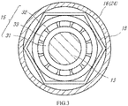
- FIG. 3 is a diagram showing the rear bearing 15 and its vicinity when viewed in the axial direction.
- the rear bearing 15 is a cageless ball bearing that includes an inner race 31, an outer race 32, and balls 33 but does not include a cage that holds the balls 33. Since the cage is omitted, seizure of the cage does not occur, and seizure of the entire rear bearing 15 can be suppressed.
- the rear bearing 15 of the present embodiment is a ceramic bearing in which the inner race 31, the outer race 32, and the balls 33 are made of ceramics or a hybrid bearing in which the inner race 31 and the outer race 32 are made of metal, and the balls 33 are made of ceramics.
- all of the inner race 31, the outer race 32, and the balls 33 may be made of metal.
- the rotating shaft 13 is supported by the front bearing 14 and the rear bearing 15.
- the engine 100 may include another bearing that supports the rotating shaft 13.
- the engine 100 may include three or more bearings.
- the housing 16 includes an outer housing 21 and an inner housing 22.
- the outer housing 21 forms an outer shell of the engine 100
- the inner housing 22 is located inside the outer housing 21.
- the outer housing 21 and the inner housing 22 form a passage of the air and the combustion gas.
- the inner housing 22 includes a hollow front housing 23 and a hollow rear housing 24.
- the front housing 23 is located at the front side of the compressor 10, and the rear housing 24 is located at the rear side of the turbine 12.
- the outer housing 21 and the inner housing 22 are coupled to each other by a post or a stationary blade extending in a radial direction between the outer housing 21 and the inner housing 22.
- a material of the housing 16 and a material of the rotating shaft 13 are different from each other. Therefore, the housing 16 and the rotating shaft 13 are different in the coefficient of thermal expansion from each other, and the housing 16 and the rotating shaft 13 are different in the amount of change of an axial dimension by the thermal expansion from each other. Therefore, when the engine 100 starts, the positioning error in the axial direction is generated between the rotating shaft 13 and the housing 16. To be specific, a portion of the rotating shaft 13 and a portion of the housing 16 which have been located at the same axial position before the operation of the engine 100 are located at different axial positions from each other after the operation of the engine 100. The above positioning error increases in a direction away from the portion corresponding to the front bearing 14 as the reference point. When the housing 16 and the rotating shaft 13 are different in temperature from each other although the material of the housing 16 and the material of the rotating shaft 13 are the same as each other, the positioning error in the axial direction by the thermal expansion occurs.
- the lubricator 17 is a device that supplies lubricating oil to the front bearing 14 and the rear bearing 15.
- the lubricator 17 of the present embodiment is a non-circulation lubricator that injects disposable lubricating oil to the front bearing 14 and the rear bearing 15.
- the lubricator 17 mixes the lubricating oil with the compressed air extracted from the compressor 10, and injects a mixture of the oil and the air to the front bearing 14 and the rear bearing 15.
- the lubricator 17 may inject the lubricating oil without mixing the lubricating oil with the compressed air and may be a circulation lubricator that collects and reuses the used lubricating oil.
- the lubricator 17 of the present embodiment can be manufactured at low cost since the lubricator 17 does not have to include a mechanism that circulates the lubricating oil.
- the amount of lubricating oil supplied to the bearings 14 and 15 by the lubricator 17 is smaller than that by a circulation lubricator. Therefore, in the present embodiment, coolability of cooling the bearings 14 and 15 by the lubricating oil is limited. Especially, the seizure of the rear bearing 15 that becomes high in temperature tends to occur.
- a bearing that is a hybrid bearing and is a cageless ball bearing is adopted as the rear bearing 15 of the present embodiment, the seizure of the rear bearing 15 is suppressed.
- the ball bearing breaks more easily than the roller bearing.
- the engine 100 includes the rear bearing holding member 18.
- the rear bearing holding member 18 is a member that is interposed between the rear bearing 15 and the housing 16 and holds the rear bearing 15.
- the rear bearing holding member 18 of the present embodiment is formed by a metal plate. As shown in FIG. 3 , the rear bearing holding member 18 has a tubular shape that is polygonal when viewed in the axial direction.
- the rear bearing holding member 18 is inscribed in the housing 16 and circumscribed about the rear bearing 15. To be specific, portions of the rear bearing holding member 18 which portions correspond to vertexes of the polygon are in contact with the housing 16, and intermediate portions each between the adjacent vertexes are in contact with the outer race 32 of the rear bearing 15.
- the rear bearing holding member 18 is fixed to the housing 16. Moreover, the rear bearing holding member 18 holds the outer race 32 of the rear bearing 15. More specifically, the rear bearing holding member 18 holds the outer race 28 of the rear bearing 15 such that the outer race 28 is slidable in the axial direction. Therefore, even if the positioning error between the housing 16 and the rotating shaft 13 in the axial direction occurs by the thermal expansion, the outer race 32 of the rear bearing 15 moves in the axial direction relative to the housing 16, and therefore, a large positioning error does not occur between the outer race 32 and the inner race 31 of the rear bearing 15. With this, the breakage of the rear bearing 15 can be avoided.
- the rear bearing holding member 18 elastically deforms, and for example, by friction between the rear bearing holding member 18 and the housing 16, portions of the rear bearing holding member 18 which portions hold the rear bearing 15 (i.e., portions of the rear bearing holding member 18 which portions are in contact with the rear bearing 15) move in the radial direction relative to the housing 16 while attenuating vibration of the rear bearing 15.
- the rear bearing holding member 18 holds the rear bearing 15 such that the rear bearing 15 is movable in the radial direction relative to the housing 16 while being attenuated. Therefore, the rear bearing holding member 18 serves as a damper that attenuates the vibration of the rear bearing 15 in the radial direction.
- the rear bearing holding member 18 is not limited to the configuration shown in FIG. 3 .
- the rear bearing holding member 18 may have the configuration shown in FIG. 4.
- FIG. 4 is a diagram showing the rear bearing holding member 18 of a modified example and its vicinity when viewed in the axial direction.
- the rear bearing holding member 18 of the modified example includes elastic members 34.
- the elastic members 34 are so-called coil springs and are arranged at intervals in the circumferential direction of the rear bearing 15.
- Each elastic member 34 is located between the rear bearing 15 and the housing 16, and both end portions of the elastic member 34 are respectively fixed to the outer race 32 of the rear bearing 15 and the housing 16.
- each elastic member 34 couples the outer race 32 of the rear bearing 15 and the housing 16.
- the elastic member 34 is elastically deformable in the axial direction and the radial direction of the rear bearing 15. Therefore, a portion of the elastic member 34 which portion is coupled to the rear bearing 15 is movable in the axial direction relative to the housing 16.
- the vibration damping effect of this configuration in the radial direction is smaller than that of the configuration shown in FIG. 3
- the configuration shown in FIG. 3 is more desirable from the viewpoint of the vibration damping effect.
- the rear bearing holding member 18 may have a configuration other than the configurations shown in FIGS. 3 and 4 .
- the rear bearing holding member 18 may be configured by combining a member that elastically deforms in the axial direction of the rear bearing 15 and a member that elastically deforms in the radial direction of the rear bearing 15.
- a gas turbine engine includes: a compressor that compresses air which has been taken in; a combustor that sprays a fuel to the air compressed by the compressor and combusts the fuel; a turbine that is rotated by energy of a combustion gas generated by the combustor; a rotating shaft that couples the compressor and the turbine; a rear bearing that is a cageless ball bearing including an inner race, an outer race, and a ball, the inner race being fixed to a portion of the rotating shaft which portion is close to the turbine; a housing to which the rear bearing is attached; and a rear bearing holding member that is interposed between the rear bearing and the housing and holds the outer race of the rear bearing such that the outer race of the rear bearing is movable in an axial direction relative to the housing.
- the outer race of the rear bearing is held so as to be movable in the axial direction relative to the housing. Therefore, even if the positioning error between the housing and the rotating shaft in the axial direction occurs by the thermal expansion, a large positioning error between the outer race and the inner race of the rear bearing does not occur, and therefore, the breakage of the rear bearing can be avoided.
- a cageless ball bearing whose seizure hardly occurs can be adopted as the rear bearing.
- the gas turbine engine according to the present embodiment further includes a front bearing including an inner race, an outer race, and a ball, the inner race being fixed to a portion of the rotating shaft which portion is close to the compressor, the outer race being fixed to the housing so as not to be movable in the axial direction relative to the housing.
- the rear bearing is movable in the axial direction relative to the housing, and the front bearing is fixed so as not to be movable in the axial direction relative to the housing. With this, the rotating shaft can be stably held.
- the rear bearing holding member holds the outer race of the rear bearing such that the rear bearing is movable in a radial direction relative to the housing.
- the rear bearing holding member can hold the rear bearing even if the rear bearing moves in the radial direction by vibration or the like.
- a portion of the rear bearing holding member which portion holds the outer race of the rear bearing is movable in the radial direction relative to the housing while attenuating vibration of the rear bearing.
- the rear bearing holding member can hold the rear bearing such that the rear bearing is movable in both the axial direction and the radial direction relative to the housing.
- the rear bearing holding member includes an elastic member that is elastically deformable in the axial direction and the radial direction relative to the housing, and the rear bearing holding member holds the rear bearing through the elastic member.
- the rear bearing holding member can hold the rear bearing such that the rear bearing is movable in both the axial direction and the radial direction relative to the housing. As a result, the breakage of the rear bearing during the operation of the gas turbine engine can be prevented.
- the rear bearing is a ceramic bearing in which the inner race, the outer race, and the ball are made of ceramics or a hybrid bearing in which the inner race and the outer race are made of metal, and the ball is made of ceramics.
- the rear bearing is the ceramic bearing or the hybrid bearing, the seizure of the rear bearing can be further suppressed.
- the gas turbine engine according to the present embodiment further includes a non-circulation lubricator that injects lubricating oil to the rear bearing.
- the manufacturing cost of the lubricator can be suppressed.
- various problems tend to occur since the amount of lubricating oil supplied to the rear bearing is small.
- the gas turbine engine includes the above rear bearing holding member, these problems can be solved.
Landscapes
- Engineering & Computer Science (AREA)
- General Engineering & Computer Science (AREA)
- Mechanical Engineering (AREA)
- Chemical & Material Sciences (AREA)
- Combustion & Propulsion (AREA)
- Oil, Petroleum & Natural Gas (AREA)
- Ceramic Engineering (AREA)
- Rolling Contact Bearings (AREA)
- Support Of The Bearing (AREA)
- Mounting Of Bearings Or Others (AREA)
Applications Claiming Priority (2)
| Application Number | Priority Date | Filing Date | Title |
|---|---|---|---|
| JP2020023237A JP7445453B2 (ja) | 2020-02-14 | 2020-02-14 | ガスタービンエンジン |
| PCT/JP2021/005257 WO2021162092A1 (ja) | 2020-02-14 | 2021-02-12 | ガスタービンエンジン |
Publications (3)
| Publication Number | Publication Date |
|---|---|
| EP4105461A1 true EP4105461A1 (de) | 2022-12-21 |
| EP4105461A4 EP4105461A4 (de) | 2024-03-13 |
| EP4105461B1 EP4105461B1 (de) | 2025-06-04 |
Family
ID=77292729
Family Applications (1)
| Application Number | Title | Priority Date | Filing Date |
|---|---|---|---|
| EP21753566.5A Active EP4105461B1 (de) | 2020-02-14 | 2021-02-12 | Gasturbinentriebwerk |
Country Status (4)
| Country | Link |
|---|---|
| US (1) | US11840960B2 (de) |
| EP (1) | EP4105461B1 (de) |
| JP (1) | JP7445453B2 (de) |
| WO (1) | WO2021162092A1 (de) |
Family Cites Families (10)
| Publication number | Priority date | Publication date | Assignee | Title |
|---|---|---|---|---|
| JPH0737811B2 (ja) * | 1992-03-31 | 1995-04-26 | 株式会社牧野フライス製作所 | 主軸装置 |
| US6478553B1 (en) * | 2001-04-24 | 2002-11-12 | General Motors Corporation | High thrust turbocharger rotor with ball bearings |
| JP3636329B1 (ja) * | 2004-08-17 | 2005-04-06 | 川崎重工業株式会社 | 軸受振動減衰機構 |
| US9500231B2 (en) * | 2011-09-30 | 2016-11-22 | Williams International Co., L.L.C. | Fractured-outer-race full-complement ball-bearing system incorporated in a turbocharger assembly |
| US20140010648A1 (en) * | 2012-06-29 | 2014-01-09 | United Technologies Corporation | Sleeve for turbine bearing stack |
| FR3013385B1 (fr) * | 2013-11-21 | 2015-11-13 | Snecma | Enceinte avant etanche lors du desassemblage modulaire d'un turboreacteur a reducteur |
| DE102016203423A1 (de) * | 2016-03-02 | 2017-09-07 | Dürr Systems Ag | Gasturbinensystem |
| US9926975B2 (en) * | 2016-03-22 | 2018-03-27 | United Technologies Corporation | Centering spring and damper assembly |
| US9915174B1 (en) * | 2017-01-31 | 2018-03-13 | United Technologies Corporation | Aerated squeeze-film damper |
| JP6862292B2 (ja) | 2017-06-19 | 2021-04-21 | 川崎重工業株式会社 | ガスタービンエンジン |
-
2020
- 2020-02-14 JP JP2020023237A patent/JP7445453B2/ja active Active
-
2021
- 2021-02-12 US US17/799,004 patent/US11840960B2/en active Active
- 2021-02-12 EP EP21753566.5A patent/EP4105461B1/de active Active
- 2021-02-12 WO PCT/JP2021/005257 patent/WO2021162092A1/ja not_active Ceased
Also Published As
| Publication number | Publication date |
|---|---|
| EP4105461B1 (de) | 2025-06-04 |
| EP4105461A4 (de) | 2024-03-13 |
| US11840960B2 (en) | 2023-12-12 |
| US20230108755A1 (en) | 2023-04-06 |
| WO2021162092A1 (ja) | 2021-08-19 |
| JP2021127733A (ja) | 2021-09-02 |
| JP7445453B2 (ja) | 2024-03-07 |
Similar Documents
| Publication | Publication Date | Title |
|---|---|---|
| EP3236095B1 (de) | Lager | |
| US8100646B2 (en) | Two-shaft engine for an aircraft gas turbine | |
| US10036279B2 (en) | Thrust bearing | |
| CN107120191A (zh) | 具有定心弹簧和挤压膜阻尼器的芯部差动轴承 | |
| EP1331364A2 (de) | Elastische Verbindungsmuffe für ein Dienstrohr in einem Doppelmantellagergehäuse | |
| EP2113639A2 (de) | Dämpfungssysteme zur Verwendung in Turbinentriebwerken | |
| EP1808580A2 (de) | Niederdrucköl verwendender Quetschöldämpfer | |
| US10001166B2 (en) | Gas distribution labyrinth for bearing pad | |
| KR20120113241A (ko) | 가스 터빈 엔진과 포일 베어링 시스템 | |
| US10738653B2 (en) | Squeeze film damper assemblies | |
| US11274557B2 (en) | Damper assemblies for rotating drum rotors of gas turbine engines | |
| US20100247015A1 (en) | Bearing arrangement | |
| EP3851689A1 (de) | Lagerträger mit zerbrechlichen laschen | |
| EP4105461A1 (de) | Gasturbinentriebwerk | |
| US20180335087A1 (en) | Bearing cages for roller bearing assemblies | |
| US11326472B2 (en) | Turbine engine comprising means for axially homogenising the temperature of an inner ring of a roller bearing | |
| US20240052890A1 (en) | Air turbine starter with bearing support structure | |
| CN114962002B (zh) | 带有弹性支撑的轴承组件及航空发动机 | |
| CN113728156B (zh) | 具有反向旋转涡轮机的涡轮发动机的改进结构 | |
| US11746699B2 (en) | Gas turbine engine | |
| US20200232509A1 (en) | Roller Bearing Assembly | |
| RU2802490C2 (ru) | Улучшенная конструкция газотурбинного двигателя с биротативной турбиной с противоположным вращением валов | |
| JPH02196137A (ja) | ガスタービン | |
| US10054163B2 (en) | Bearing cages for roller bearing assemblies | |
| KR20250053955A (ko) | 중간축 커버, 및 이를 구비하는 가스 터빈 |
Legal Events
| Date | Code | Title | Description |
|---|---|---|---|
| STAA | Information on the status of an ep patent application or granted ep patent |
Free format text: STATUS: THE INTERNATIONAL PUBLICATION HAS BEEN MADE |
|
| PUAI | Public reference made under article 153(3) epc to a published international application that has entered the european phase |
Free format text: ORIGINAL CODE: 0009012 |
|
| STAA | Information on the status of an ep patent application or granted ep patent |
Free format text: STATUS: REQUEST FOR EXAMINATION WAS MADE |
|
| 17P | Request for examination filed |
Effective date: 20220815 |
|
| AK | Designated contracting states |
Kind code of ref document: A1 Designated state(s): AL AT BE BG CH CY CZ DE DK EE ES FI FR GB GR HR HU IE IS IT LI LT LU LV MC MK MT NL NO PL PT RO RS SE SI SK SM TR |
|
| DAV | Request for validation of the european patent (deleted) | ||
| DAX | Request for extension of the european patent (deleted) | ||
| REG | Reference to a national code |
Ref country code: DE Ref legal event code: R079 Free format text: PREVIOUS MAIN CLASS: F02C0007060000 Ref country code: DE Ref legal event code: R079 Ref document number: 602021031821 Country of ref document: DE Free format text: PREVIOUS MAIN CLASS: F02C0007060000 Ipc: F01D0025160000 |
|
| A4 | Supplementary search report drawn up and despatched |
Effective date: 20240214 |
|
| RIC1 | Information provided on ipc code assigned before grant |
Ipc: F16C 33/58 20060101ALI20240208BHEP Ipc: F16C 25/08 20060101ALI20240208BHEP Ipc: F01D 25/00 20060101ALI20240208BHEP Ipc: F02C 7/06 20060101ALI20240208BHEP Ipc: F01D 25/16 20060101AFI20240208BHEP |
|
| REG | Reference to a national code |
Ref country code: DE Ref legal event code: R079 Ref country code: DE Ref legal event code: R079 Ref document number: 602021031821 Country of ref document: DE Free format text: PREVIOUS MAIN CLASS: F01D0025160000 Ipc: F16C0019020000 |
|
| GRAP | Despatch of communication of intention to grant a patent |
Free format text: ORIGINAL CODE: EPIDOSNIGR1 |
|
| RIC1 | Information provided on ipc code assigned before grant |
Ipc: F16N 7/32 20060101ALI20250114BHEP Ipc: F16N 7/38 20060101ALI20250114BHEP Ipc: F16C 23/08 20060101ALI20250114BHEP Ipc: F16C 35/077 20060101ALI20250114BHEP Ipc: F16C 35/04 20060101ALI20250114BHEP Ipc: F16C 27/04 20060101ALI20250114BHEP Ipc: F16C 33/66 20060101ALI20250114BHEP Ipc: F16C 33/30 20060101ALI20250114BHEP Ipc: F02C 7/06 20060101ALI20250114BHEP Ipc: F01D 25/16 20060101ALI20250114BHEP Ipc: F16C 19/02 20060101AFI20250114BHEP |
|
| STAA | Information on the status of an ep patent application or granted ep patent |
Free format text: STATUS: GRANT OF PATENT IS INTENDED |
|
| INTG | Intention to grant announced |
Effective date: 20250220 |
|
| GRAS | Grant fee paid |
Free format text: ORIGINAL CODE: EPIDOSNIGR3 |
|
| GRAA | (expected) grant |
Free format text: ORIGINAL CODE: 0009210 |
|
| STAA | Information on the status of an ep patent application or granted ep patent |
Free format text: STATUS: THE PATENT HAS BEEN GRANTED |
|
| AK | Designated contracting states |
Kind code of ref document: B1 Designated state(s): AL AT BE BG CH CY CZ DE DK EE ES FI FR GB GR HR HU IE IS IT LI LT LU LV MC MK MT NL NO PL PT RO RS SE SI SK SM TR |
|
| REG | Reference to a national code |
Ref country code: GB Ref legal event code: FG4D |
|
| REG | Reference to a national code |
Ref country code: CH Ref legal event code: EP |
|
| REG | Reference to a national code |
Ref country code: DE Ref legal event code: R096 Ref document number: 602021031821 Country of ref document: DE |
|
| REG | Reference to a national code |
Ref country code: IE Ref legal event code: FG4D |
|
| REG | Reference to a national code |
Ref country code: NL Ref legal event code: MP Effective date: 20250604 |
|
| PG25 | Lapsed in a contracting state [announced via postgrant information from national office to epo] |
Ref country code: FI Free format text: LAPSE BECAUSE OF FAILURE TO SUBMIT A TRANSLATION OF THE DESCRIPTION OR TO PAY THE FEE WITHIN THE PRESCRIBED TIME-LIMIT Effective date: 20250604 Ref country code: ES Free format text: LAPSE BECAUSE OF FAILURE TO SUBMIT A TRANSLATION OF THE DESCRIPTION OR TO PAY THE FEE WITHIN THE PRESCRIBED TIME-LIMIT Effective date: 20250604 |
|
| REG | Reference to a national code |
Ref country code: LT Ref legal event code: MG9D |
|
| PG25 | Lapsed in a contracting state [announced via postgrant information from national office to epo] |
Ref country code: NO Free format text: LAPSE BECAUSE OF FAILURE TO SUBMIT A TRANSLATION OF THE DESCRIPTION OR TO PAY THE FEE WITHIN THE PRESCRIBED TIME-LIMIT Effective date: 20250904 Ref country code: GR Free format text: LAPSE BECAUSE OF FAILURE TO SUBMIT A TRANSLATION OF THE DESCRIPTION OR TO PAY THE FEE WITHIN THE PRESCRIBED TIME-LIMIT Effective date: 20250905 |
|
| PG25 | Lapsed in a contracting state [announced via postgrant information from national office to epo] |
Ref country code: PL Free format text: LAPSE BECAUSE OF FAILURE TO SUBMIT A TRANSLATION OF THE DESCRIPTION OR TO PAY THE FEE WITHIN THE PRESCRIBED TIME-LIMIT Effective date: 20250604 |
|
| PG25 | Lapsed in a contracting state [announced via postgrant information from national office to epo] |
Ref country code: BG Free format text: LAPSE BECAUSE OF FAILURE TO SUBMIT A TRANSLATION OF THE DESCRIPTION OR TO PAY THE FEE WITHIN THE PRESCRIBED TIME-LIMIT Effective date: 20250604 |
|
| PG25 | Lapsed in a contracting state [announced via postgrant information from national office to epo] |
Ref country code: HR Free format text: LAPSE BECAUSE OF FAILURE TO SUBMIT A TRANSLATION OF THE DESCRIPTION OR TO PAY THE FEE WITHIN THE PRESCRIBED TIME-LIMIT Effective date: 20250604 |
|
| PG25 | Lapsed in a contracting state [announced via postgrant information from national office to epo] |
Ref country code: RS Free format text: LAPSE BECAUSE OF FAILURE TO SUBMIT A TRANSLATION OF THE DESCRIPTION OR TO PAY THE FEE WITHIN THE PRESCRIBED TIME-LIMIT Effective date: 20250904 |
|
| PG25 | Lapsed in a contracting state [announced via postgrant information from national office to epo] |
Ref country code: LV Free format text: LAPSE BECAUSE OF FAILURE TO SUBMIT A TRANSLATION OF THE DESCRIPTION OR TO PAY THE FEE WITHIN THE PRESCRIBED TIME-LIMIT Effective date: 20250604 |
|
| PG25 | Lapsed in a contracting state [announced via postgrant information from national office to epo] |
Ref country code: NL Free format text: LAPSE BECAUSE OF FAILURE TO SUBMIT A TRANSLATION OF THE DESCRIPTION OR TO PAY THE FEE WITHIN THE PRESCRIBED TIME-LIMIT Effective date: 20250604 |
|
| PG25 | Lapsed in a contracting state [announced via postgrant information from national office to epo] |
Ref country code: PT Free format text: LAPSE BECAUSE OF FAILURE TO SUBMIT A TRANSLATION OF THE DESCRIPTION OR TO PAY THE FEE WITHIN THE PRESCRIBED TIME-LIMIT Effective date: 20251006 |
|
| REG | Reference to a national code |
Ref country code: AT Ref legal event code: MK05 Ref document number: 1800580 Country of ref document: AT Kind code of ref document: T Effective date: 20250604 |
|
| PG25 | Lapsed in a contracting state [announced via postgrant information from national office to epo] |
Ref country code: IS Free format text: LAPSE BECAUSE OF FAILURE TO SUBMIT A TRANSLATION OF THE DESCRIPTION OR TO PAY THE FEE WITHIN THE PRESCRIBED TIME-LIMIT Effective date: 20251004 |
|
| PG25 | Lapsed in a contracting state [announced via postgrant information from national office to epo] |
Ref country code: AT Free format text: LAPSE BECAUSE OF FAILURE TO SUBMIT A TRANSLATION OF THE DESCRIPTION OR TO PAY THE FEE WITHIN THE PRESCRIBED TIME-LIMIT Effective date: 20250604 Ref country code: SM Free format text: LAPSE BECAUSE OF FAILURE TO SUBMIT A TRANSLATION OF THE DESCRIPTION OR TO PAY THE FEE WITHIN THE PRESCRIBED TIME-LIMIT Effective date: 20250604 |
|
| PG25 | Lapsed in a contracting state [announced via postgrant information from national office to epo] |
Ref country code: CZ Free format text: LAPSE BECAUSE OF FAILURE TO SUBMIT A TRANSLATION OF THE DESCRIPTION OR TO PAY THE FEE WITHIN THE PRESCRIBED TIME-LIMIT Effective date: 20250604 |
|
| PG25 | Lapsed in a contracting state [announced via postgrant information from national office to epo] |
Ref country code: EE Free format text: LAPSE BECAUSE OF FAILURE TO SUBMIT A TRANSLATION OF THE DESCRIPTION OR TO PAY THE FEE WITHIN THE PRESCRIBED TIME-LIMIT Effective date: 20250604 |
|
| PG25 | Lapsed in a contracting state [announced via postgrant information from national office to epo] |
Ref country code: SK Free format text: LAPSE BECAUSE OF FAILURE TO SUBMIT A TRANSLATION OF THE DESCRIPTION OR TO PAY THE FEE WITHIN THE PRESCRIBED TIME-LIMIT Effective date: 20250604 |
|
| PG25 | Lapsed in a contracting state [announced via postgrant information from national office to epo] |
Ref country code: IT Free format text: LAPSE BECAUSE OF FAILURE TO SUBMIT A TRANSLATION OF THE DESCRIPTION OR TO PAY THE FEE WITHIN THE PRESCRIBED TIME-LIMIT Effective date: 20250604 |
|
| PG25 | Lapsed in a contracting state [announced via postgrant information from national office to epo] |
Ref country code: RO Free format text: LAPSE BECAUSE OF FAILURE TO SUBMIT A TRANSLATION OF THE DESCRIPTION OR TO PAY THE FEE WITHIN THE PRESCRIBED TIME-LIMIT Effective date: 20250604 |
|
| REG | Reference to a national code |
Ref country code: DE Ref legal event code: R097 Ref document number: 602021031821 Country of ref document: DE |
|
| PGFP | Annual fee paid to national office [announced via postgrant information from national office to epo] |
Ref country code: GB Payment date: 20260107 Year of fee payment: 6 |
|
| PLBE | No opposition filed within time limit |
Free format text: ORIGINAL CODE: 0009261 |
|
| STAA | Information on the status of an ep patent application or granted ep patent |
Free format text: STATUS: NO OPPOSITION FILED WITHIN TIME LIMIT |
|
| PG25 | Lapsed in a contracting state [announced via postgrant information from national office to epo] |
Ref country code: DK Free format text: LAPSE BECAUSE OF FAILURE TO SUBMIT A TRANSLATION OF THE DESCRIPTION OR TO PAY THE FEE WITHIN THE PRESCRIBED TIME-LIMIT Effective date: 20250604 |
|
| PGFP | Annual fee paid to national office [announced via postgrant information from national office to epo] |
Ref country code: DE Payment date: 20260107 Year of fee payment: 6 |
|
| REG | Reference to a national code |
Ref country code: CH Ref legal event code: L10 Free format text: ST27 STATUS EVENT CODE: U-0-0-L10-L00 (AS PROVIDED BY THE NATIONAL OFFICE) Effective date: 20260416 |
|
| PGFP | Annual fee paid to national office [announced via postgrant information from national office to epo] |
Ref country code: FR Payment date: 20260107 Year of fee payment: 6 |