EP4105493B1 - Ensemble turbocompresseur - Google Patents
Ensemble turbocompresseur Download PDFInfo
- Publication number
- EP4105493B1 EP4105493B1 EP21179246.0A EP21179246A EP4105493B1 EP 4105493 B1 EP4105493 B1 EP 4105493B1 EP 21179246 A EP21179246 A EP 21179246A EP 4105493 B1 EP4105493 B1 EP 4105493B1
- Authority
- EP
- European Patent Office
- Prior art keywords
- compressor wheel
- insert unit
- air intake
- intake channel
- end portion
- Prior art date
- Legal status (The legal status is an assumption and is not a legal conclusion. Google has not performed a legal analysis and makes no representation as to the accuracy of the status listed.)
- Active
Links
Images


Classifications
-
- F—MECHANICAL ENGINEERING; LIGHTING; HEATING; WEAPONS; BLASTING
- F04—POSITIVE - DISPLACEMENT MACHINES FOR LIQUIDS; PUMPS FOR LIQUIDS OR ELASTIC FLUIDS
- F04D—NON-POSITIVE-DISPLACEMENT PUMPS
- F04D29/00—Details, component parts, or accessories
- F04D29/40—Casings; Connections of working fluid
- F04D29/42—Casings; Connections of working fluid for radial or helico-centrifugal pumps
- F04D29/44—Fluid-guiding means, e.g. diffusers
- F04D29/441—Fluid-guiding means, e.g. diffusers especially adapted for elastic fluid pumps
-
- F—MECHANICAL ENGINEERING; LIGHTING; HEATING; WEAPONS; BLASTING
- F04—POSITIVE - DISPLACEMENT MACHINES FOR LIQUIDS; PUMPS FOR LIQUIDS OR ELASTIC FLUIDS
- F04D—NON-POSITIVE-DISPLACEMENT PUMPS
- F04D27/00—Control, e.g. regulation, of pumps, pumping installations or pumping systems specially adapted for elastic fluids
- F04D27/02—Surge control
- F04D27/0253—Surge control by throttling
-
- F—MECHANICAL ENGINEERING; LIGHTING; HEATING; WEAPONS; BLASTING
- F04—POSITIVE - DISPLACEMENT MACHINES FOR LIQUIDS; PUMPS FOR LIQUIDS OR ELASTIC FLUIDS
- F04D—NON-POSITIVE-DISPLACEMENT PUMPS
- F04D29/00—Details, component parts, or accessories
- F04D29/40—Casings; Connections of working fluid
- F04D29/42—Casings; Connections of working fluid for radial or helico-centrifugal pumps
- F04D29/4206—Casings; Connections of working fluid for radial or helico-centrifugal pumps especially adapted for elastic fluid pumps
- F04D29/4213—Casings; Connections of working fluid for radial or helico-centrifugal pumps especially adapted for elastic fluid pumps suction ports
-
- F—MECHANICAL ENGINEERING; LIGHTING; HEATING; WEAPONS; BLASTING
- F04—POSITIVE - DISPLACEMENT MACHINES FOR LIQUIDS; PUMPS FOR LIQUIDS OR ELASTIC FLUIDS
- F04D—NON-POSITIVE-DISPLACEMENT PUMPS
- F04D29/00—Details, component parts, or accessories
- F04D29/40—Casings; Connections of working fluid
- F04D29/42—Casings; Connections of working fluid for radial or helico-centrifugal pumps
- F04D29/44—Fluid-guiding means, e.g. diffusers
- F04D29/46—Fluid-guiding means, e.g. diffusers adjustable
- F04D29/462—Fluid-guiding means, e.g. diffusers adjustable especially adapted for elastic fluid pumps
- F04D29/464—Fluid-guiding means, e.g. diffusers adjustable especially adapted for elastic fluid pumps adjusting flow cross-section, otherwise than by using adjustable stator blades
-
- F—MECHANICAL ENGINEERING; LIGHTING; HEATING; WEAPONS; BLASTING
- F02—COMBUSTION ENGINES; HOT-GAS OR COMBUSTION-PRODUCT ENGINE PLANTS
- F02B—INTERNAL-COMBUSTION PISTON ENGINES; COMBUSTION ENGINES IN GENERAL
- F02B37/00—Engines characterised by provision of pumps driven at least for part of the time by exhaust
- F02B37/12—Control of the pumps
- F02B37/22—Control of the pumps by varying cross-section of exhaust passages or air passages, e.g. by throttling turbine inlets or outlets or by varying effective number of guide conduits
- F02B37/225—Control of the pumps by varying cross-section of exhaust passages or air passages, e.g. by throttling turbine inlets or outlets or by varying effective number of guide conduits air passages
-
- F—MECHANICAL ENGINEERING; LIGHTING; HEATING; WEAPONS; BLASTING
- F02—COMBUSTION ENGINES; HOT-GAS OR COMBUSTION-PRODUCT ENGINE PLANTS
- F02M—SUPPLYING COMBUSTION ENGINES IN GENERAL WITH COMBUSTIBLE MIXTURES OR CONSTITUENTS THEREOF
- F02M35/00—Combustion-air cleaners, air intakes, intake silencers, or induction systems specially adapted for, or arranged on, internal-combustion engines
- F02M35/10—Air intakes; Induction systems
- F02M35/10091—Air intakes; Induction systems characterised by details of intake ducts: shapes; connections; arrangements
- F02M35/10118—Air intakes; Induction systems characterised by details of intake ducts: shapes; connections; arrangements with variable cross-sections of intake ducts along their length; Venturis; Diffusers
-
- F—MECHANICAL ENGINEERING; LIGHTING; HEATING; WEAPONS; BLASTING
- F02—COMBUSTION ENGINES; HOT-GAS OR COMBUSTION-PRODUCT ENGINE PLANTS
- F02M—SUPPLYING COMBUSTION ENGINES IN GENERAL WITH COMBUSTIBLE MIXTURES OR CONSTITUENTS THEREOF
- F02M35/00—Combustion-air cleaners, air intakes, intake silencers, or induction systems specially adapted for, or arranged on, internal-combustion engines
- F02M35/10—Air intakes; Induction systems
- F02M35/1015—Air intakes; Induction systems characterised by the engine type
- F02M35/10157—Supercharged engines
-
- F—MECHANICAL ENGINEERING; LIGHTING; HEATING; WEAPONS; BLASTING
- F04—POSITIVE - DISPLACEMENT MACHINES FOR LIQUIDS; PUMPS FOR LIQUIDS OR ELASTIC FLUIDS
- F04D—NON-POSITIVE-DISPLACEMENT PUMPS
- F04D29/00—Details, component parts, or accessories
- F04D29/40—Casings; Connections of working fluid
- F04D29/42—Casings; Connections of working fluid for radial or helico-centrifugal pumps
- F04D29/44—Fluid-guiding means, e.g. diffusers
- F04D29/46—Fluid-guiding means, e.g. diffusers adjustable
- F04D29/462—Fluid-guiding means, e.g. diffusers adjustable especially adapted for elastic fluid pumps
-
- F—MECHANICAL ENGINEERING; LIGHTING; HEATING; WEAPONS; BLASTING
- F05—INDEXING SCHEMES RELATING TO ENGINES OR PUMPS IN VARIOUS SUBCLASSES OF CLASSES F01-F04
- F05D—INDEXING SCHEME FOR ASPECTS RELATING TO NON-POSITIVE-DISPLACEMENT MACHINES OR ENGINES, GAS-TURBINES OR JET-PROPULSION PLANTS
- F05D2260/00—Function
- F05D2260/50—Kinematic linkage, i.e. transmission of position
- F05D2260/57—Kinematic linkage, i.e. transmission of position using servos, independent actuators, etc.
-
- Y—GENERAL TAGGING OF NEW TECHNOLOGICAL DEVELOPMENTS; GENERAL TAGGING OF CROSS-SECTIONAL TECHNOLOGIES SPANNING OVER SEVERAL SECTIONS OF THE IPC; TECHNICAL SUBJECTS COVERED BY FORMER USPC CROSS-REFERENCE ART COLLECTIONS [XRACs] AND DIGESTS
- Y02—TECHNOLOGIES OR APPLICATIONS FOR MITIGATION OR ADAPTATION AGAINST CLIMATE CHANGE
- Y02T—CLIMATE CHANGE MITIGATION TECHNOLOGIES RELATED TO TRANSPORTATION
- Y02T10/00—Road transport of goods or passengers
- Y02T10/10—Internal combustion engine [ICE] based vehicles
- Y02T10/12—Improving ICE efficiencies
Definitions
- the present disclosure relates to a turbo compressor assembly, a vehicle comprising such a turbo compressor assembly, a method for manufacturing such a turbo compressor assembly.
- turbo charger In order to reduce pollutant emissions and to decrease fuel consumption, conventional vehicles comprise a turbo charger.
- the turbo charger utilizes energy of exhaust gas of an internal combustion engine to compress intake air.
- a conventional turbo charger comprises a turbine with an exhaust gas turbine wheel and a compressor with a compressor wheel. The compressor wheel and the exhaust gas turbine wheel are coupled to one another by a solid shaft.
- the exhaust gas turbine wheel converts energy of the exhaust gas into mechanical energy to drive the compressor wheel, which compresses the intake air into a pressurized air stream.
- the pressurized air stream is supplied to an inlet manifold on the internal combustion engine to improve performance of the engine.
- a compressor surge in other words violent airflow oscillating, may occur, which would decrease an efficiency of the compressor. Additionally, near surge instability may cause wear on bearing components of the turbo charger and noise vibration harshness (NVH) issues of the vehicle when air to be compressed is separated from blades of the compressor wheel and induces flow noise.
- NASH noise vibration harshness
- US 2019/264603 A1 discloses a turbocharger for a combustion machine.
- the turbocharger comprises a bearing housing, in which a rotor shaft is mounted, a compressor having a compressor wheel, a fresh air supply channel and a flow control device.
- the flow control device is adjustable between an open position, in which the first flow cross section is opened up, and a closed position, in which the first flow cross section is reduced to a second flow cross section.
- DE 10 2014 006463 discloses an adjustable air supply device, in particular for a compressor in an intake tract of an internal combustion engine.
- the device comprises an air duct and an adjustable flow component for a variable setting of a flow cross-section in the air duct. With an adjustment of the flow component, a flow cross section of a flow path lying on an outside of the flow component can be changed.
- the flow component is designed as a hollow body and has an additional, internal flow path.
- a turbo compressor assembly comprises an air intake channel, a compressor wheel, an insert unit and an actuator unit.
- the air intake channel is configured to draw air to the compressor wheel and the compressor wheel is configured to rotate for compressing the drawn air from the air intake channel.
- the insert unit is arranged between the air intake channel and the compressor wheel and configured to control an airflow to the compressor wheel.
- the actuator unit is connected to the insert unit and configured to move the insert unit at least partially along the air intake channel.
- the turbo compressor assembly may control a speed of the drawn air through the air intake channel by variably positioning the insert unit between the air intake channel and the compressor wheel by means of the actuator unit.
- the insert unit may adapt the air speed at both of high mass flow rate and low mass flow rate at the compressor wheel. Accordingly, a compressor surge may be reduced or even avoided and a stable air supply to the compressor wheel can be achieved. Further, such a turbo compressor assembly may be integrated in a conventional turbo charger, which may lead to saving of manufacturing costs and time.
- a turbo charger may comprise the turbo compressor assembly and a turbine assembly.
- the compressor wheel of the turbo compressor assembly may be rotated by a shaft connected to the turbine assembly.
- the air intake channel may be arranged to guide air in direction to the compressor wheel.
- air may be drawn to the compressor wheel through the air intake channel by rotating the compressor wheel.
- the compressor wheel may further pressurize the intake air into the compressor wheel by rotating.
- intake air may be understood as ambient air sucked in the air intake channel due to rotation of the compressor wheel.
- the insert unit may face the compressor wheel and at least partially extend in the air intake channel.
- the actuator unit may be fixedly mounted at the insert unit to allow a movement of the insert unit between the air intake channel and the compressor wheel.
- the actuator unit may comprise an electric actuator.
- the actuator may allow the insert unit to approach to the compressor wheel and/or retreat from the compressor wheel. Accordingly, the insert unit may adjust the speed of the air drawn through the air intake channel and control an airflow property such laminate, turbulent, backflow, surge or the like with respect to the mass flow rate at the compressor wheel.
- the turbo compressor assembly further comprises a transition element between the compressor wheel and the air intake channel, wherein the insert unit is movable along an inner surface of the transition element.
- the transition element may connect the compressor wheel and the air intake channel.
- the transition element may be a part of the air intake channel or additionally mounted between the compressor wheel and the air intake channel.
- the insert unit may be arranged adjacent to the inner surface of the transition element and may be guided by the inner surface of the transition element when moving between the compressor wheel and the air intake channel.
- the transition element comprises a first end portion and a second end portion, the first end portion faces the compressor wheel and the second end portion faces the air intake channel.
- An inner diameter of the first end portion is smaller than an inner diameter of the second end portion of the transition element.
- the transition element may be formed in a conical shape, wherein the inner diameter of the transition element may be gradually reduced in the direction of the compressor wheel or gradually increased in the direction of the air intake channel. Accordingly, if the insert unit moves along the inner surface of the transition element, a size of an air outlet of the insert unit facing the compressor wheel may vary along the inner diameter of the transition element. This may affect the speed of intake air directed to the compressor wheel from the insert unit and/or the air intake channel.
- a working range of the turbo charger may have two limits - a choke range for high mass flow rates and a compressor surge range for low mass flow rates.
- the compressor surge may lead to instabilities in the turbo charger with appearance of reversed flow at a compressor wheel air inlet. Deep surge may be even dangerous due to mechanical damages caused by these instabilities.
- the compressor surge may occur when the mass flow rate of the compressor wheel is higher than the speed of the intake air, particularly at a low mass flow rate.
- the speed of the intake air may be adjusted. Consequently, forming of the compressor surge may be suppressed.
- the insert unit may be positioned directly ahead of the compressor wheel or at the first end portion of the transition element, at which the diameter of the air outlet of the insert unit facing the compressor wheel is decreased. Accordingly, the speed of the air drawn into the compressor wheel may be increased, i.e. adapted to the low mass flow rate of the compressor wheel.
- the air outlet of the insert unit facing the compressor wheel may be positioned apart from the compressor wheel or at the second end portion of the transition element. Accordingly, the diameter of the air outlet of the insert unit facing the compressor wheel may be increased and the speed of the air directed to the compressor wheel may be decreased and/or adapted to the high mass flow rate of the compressor wheel.
- the speed of drawn air to the compressor wheel through the air intake channel may be adjusted according to the mass flow rate of the air at the compressor wheel and formation of the compressor surge may be avoided.
- the first end portion of the transition element facing the compressor wheel may be bigger than the second end portion of the transition element facing the air intake channel.
- the actuator unit comprises a linear actuator configured to linearly move the insert unit parallel to a rotation axis of the compressor wheel.
- the actuator unit may be mounted at the insert unit on an extension of or parallel to the rotation axis of the compressor wheel.
- the actuator unit may move the insert unit linearly along a rotation axis of the compressor wheel.
- the insert unit may be approached to or retreated from the compressor wheel linearly relative to the compressor wheel.
- At least a portion of the insert unit may extend beyond the air intake channel in case the air intake channel comprises a helical shape.
- the actuator unit may be coupled with the insert unit by means of a metal bushing and the actuator unit may be air-tightly sealed such that the airflow inside the air intake channel may not be leaked.
- the actuator unit may comprise a rotating actuator configured to move the insert unit in a radial direction of the air intake channel.
- the insert unit may be guided along the air intake channel by means of the rotating actuator.
- the actuator unit with the rotating actuator may additionally comprise a rotating actuator arm fixed connected to the insert unit, which has a rotatable movement along the air intake channel.
- the insert unit comprises a guiding means facing the compressor wheel.
- the guiding means is configured to induce pre-swirl of the airflow ahead of the compressor wheel.
- the guiding means may be arranged in the transition element between the first end portion and second end portion thereof.
- the guiding means may be arranged at the air outlet of the insert unit.
- pre-swirl may be understood as the airflow reinforced by pre-turning in a radial direction of the compressor wheel, before the intake air enters the compressor wheel. Accordingly, the guiding means may support the insert unit to prevent from forming the compressor surge.
- the guiding means comprising several tab elements arranged around the rotation axis of the compressor wheel and substantially parallel to the rotation axis of the compressor wheel.
- Each of the tab elements may be formed as a blade or vane, wherein their surface may be curved.
- the plurality of the tab elements may be arranged in a cylinder shape substantially parallel to the insert element and/or the air intake channel.
- substantially parallel may be understood that each tab element may be aligned parallel to the rotation axis of the compressor wheel or with a slight inclination in the direction of the rotation axis of the compressor wheel.
- the guiding means may be configured to vary its diameter with respect to the position of an air outlet facing the compressor wheel between the first end portion and the second end portion of the transition element.
- the tab elements are arranged inclined in a rotation direction of the compressor wheel. Accordingly, the tab elements extending from the along the rotation axis of the compressor wheel may be arranged in a spiral form to direct the drawn air from the air intake channel in a radial direction of the compressor wheel. Hence, the airflow into the compressor wheel may be stabilized and a risk for the compressor surge may be reduce or remove.
- each of the tab elements comprises a ridge or fin shape projected inwardly of the guiding means.
- Each of the tab elements may comprise an edge portion extending substantially parallel to the rotation axis of the compressor wheel or in a longitudinal direction of the tab elements. Additionally, the edge portions may be also arranged in the rotation direction of the compressor wheel. Each edge portion may comprise a ridge shape or fin shape projected inwardly of the guiding means.
- the edge portions of the tab elements may also comprise a groove extending in the longitudinal direction of the tab elements. It is also possible only some tab elements comprise the ridge or fin shape and/or other tab elements comprise the groove.
- the tab elements are arranged in a closed position if the guiding means is positioned adjacent to the first end portion of the transition element.
- the guiding means of the insert unit may be arranged at the first end portion of the transition element.
- the transition element may comprise a conical shape
- the insert unit, particularly the guiding means arranged along the inner surface of the transition element may be configured to vary its diameter corresponding to the diameter of the transition element.
- the tab elements may be adapted such that it may be also arranged with the smallest diameter.
- gaps between the tab elements may be closed and/or the tab elements may be superimposed upon each other.
- the tab elements are configured to gradually open along a movement of the insert unit from the first end portion to the second end portion of the transition element. Due to the conical shape of the transition element, the guiding means may expand with respect to the movement of the insert unit along the inner surface of the transition element. The tab elements may be, hence, gradually open the gaps to increase the diameter of the guiding means.
- the insert unit comprises at least one hinge element.
- the hinge element is connected to a spring element arranged at an inner wall of the air intake channel.
- the spring element is configured to press the hinge element inwardly of the air intake channel.
- the hinge element may be configured to engage the tab elements together in position, even if an opposite side of the tab elements facing the compressor wheel may open or close along the movement of the insert unit.
- the hinge element may be further configured to adjust an open ratio of the tab elements along the movement of the insert unit between the compressor wheel and the air intake channel.
- the hinge element may comprise a first hinge section and a second hinge section.
- the first hinge section may surround the tab elements and the second hinge section may be arranged adjacent to the inner wall of the air intake channel.
- the first hinge section and the second hinge section may be coupled to each other by means of snap-fit.
- the tab elements At an engaging position of the first hinge section and the second hinge section, the tab elements may be fixedly held. Hence, the tab elements may not directly contact the inner wall of the air intake channel, which would otherwise damage the tab elements.
- the spring element arranged at the inner wall of the air intake channel may press the hinge element.
- the second hinge section may be pressed inwardly of the air intake channel as the insert unit moves from the first end portion to the second end portion of the transition element, which would lead to an expansion of the first hinge section.
- the tab elements biased by the first hinge section at the first end position of the transition unit may open gradually, as the insert unit retreats away from the compressor wheel, which may induce pre-swirl effectively at a high mass flow rate of the compressor wheel.
- the insert unit with the tab elements in the closed position may have a bigger diameter than the first end portion of the transition element such that the tab elements continuously press the inner surface of the transition element.
- the tab elements may be preloaded against the inner surface of the transition element. As the insert unit moves from the first end portion to the second end portion of the transition element, the tab elements may gradually open.
- the air intake channel comprises at least one blocking element at the inner wall.
- the blocking element is configured to limit the movement of the insert unit inside the air intake channel.
- the blocking element may be arranged in a radial direction of the air intake channel.
- the insert unit may comprise a latch element arranged at least partially around an outer surface of the insert unit. As the insert unit moves away from the compressor wheel, the latch element of the insert unit may approach to and engage with the blocking element of the air intake channel, which may block further movement of the insert unit in the opposite direction of the compressor wheel.
- the hinge element of the insert unit may be engaged with the blocking element to limit the movement of the insert unit inside the air intake channel.
- the insert unit comprises a recirculation means along a circumferential edge facing the compressor wheel.
- the recirculation means may be arranged at an outer edge of the insert unit facing the compressor wheel.
- the recirculation means may be configured to prevent a backflow of the pressurized air from the compressor wheel.
- a high pressure ratio over the compressor wheel may cause a backflow in the gap between the compressor wheel and a diffusor arranged behind the compressor wheel.
- the backflow may induce a vortex in front of the compressor wheel that blocks a laminar airflow.
- the recirculation means may be formed as a groove in a circumferential direction of the outer edge of the insert unit.
- the circumferential edge of the insert unit facing the compressor wheel may be inclined outwardly or inwardly relative to the rotation axis of the compressor wheel to avoid the backflow of the pressurized air.
- a vehicle comprises a turbo compressor assembly as described above.
- a compressor surge may be reduced or even avoided and a stable air intake through the compressor wheel can be achieved.
- an efficiency of the turbo charger, consequently the vehicle can be improved.
- a method for manufacturing a turbo compressor assembly comprises, not necessarily in this order
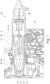
- Fig. 1 and Fig. 2 show a turbo compressor assembly 100 for a turbo charger (not shown) in a vehicle (not shown).
- the turbo charger comprises the turbo compressor assembly 100 and a turbine assembly (not shown).
- the turbo compressor assembly 100 comprises an air intake channel 10, a compressor wheel 20, an insert unit 30 and an actuator unit 40.
- the compressor wheel 20 is rotatable by a shaft 21 connected to the turbine assembly.
- the air intake channel 10 is configured to draw air to the compressor wheel 20 and the compressor wheel 20 is configured to rotate for compressing the intaken air from the air intake channel 10.
- the air intake channel 10 may be helically formed.
- the turbo compressor assembly 100 further comprises a transition element 50 between the compressor wheel 20 and the air intake channel 10.
- the transition element 50 comprises a first end portion 51 and a second end portion 52 (see also Fig 4a, Fig. 4b ).
- the first end portion 51 faces the compressor wheel 20 and the second end portion 52 facing the air intake channel 10.
- the transition element 50 has a conical shape such that an inner diameter of the first end portion 51 being smaller than an inner diameter of the second end portion 52 of the transition element 50.
- the insert unit 30 faces the compressor wheel 20 on one side and at least partially extend in the air intake channel 10 on the other side.
- the insert unit 30 is movable along an inner surface 53 of the transition element 50.
- the actuator unit 40 is fixedly connected to the insert unit 30 and allows the insert unit 30 to move between the transition element 50 and at least partially along the air intake channel 10.
- the actuator unit 40 comprises a linear actuator 41 configured to move the insert unit 30 parallel to a rotation axis of the compressor wheel 20.
- the insert unit 30 may be positioned at the first end portion 51 of the transition element 50 (see Fig. 1 ) or linearly retreated away from the compressor wheel 20 (see Fig. 2 ) by the actuator unit 40.
- the actuator unit 40 is coupled with the insert unit 30 by means of a metal bushing 43 and air-tightly sealed such that the air streaming inside the air intake channel 10 may not be leaked.
- the actuator unit 40 comprises rotating actuator 42 configured to move the insert unit 30 in a radial direction of the air intake channel 10. Since the air intake channel 10 comprises a helical shape, the insert unit 30 may be guided along with the air intake channel 10 by means of the rotating actuator 42.
- the actuator unit 40 with the rotating actuator 42 may additionally comprise a rotating actuator arm 44 fixed connected to the insert unit 30, which has a rotatable movement along the air intake channel 10 (see Fig. 3a, Fig. 3b ).
- the air intake channel 10 comprises at least one blocking element 11 at its inner wall 12.
- the blocking element 11 is configured to limit the movement of the insert unit 30.
- the blocking element 11 is configured to limit the movement of the insert unit 30.
- the blocking element 11 is arranged in a radial direction of the air intake channel 10.
- the insert unit 30 comprises a latch element arranged at least partially around an outer surface of the insert unit 30. As the insert unit 30 moves away from the compressor wheel 20, the latch element of the insert unit 30 may engage with the blocking element 11 of the air intake channel 10, which may block further movement of the insert unit 30 in the opposite direction of the compressor wheel 20.
- the insert unit 30 comprises a guiding means 31 facing the compressor wheel 20.
- the guiding means 31 is arranged in the transition element 50 between the first end portion 51 and second end portion 52 thereof.
- the guiding means 31 is configured to provide pre-swirl in front of the compressor wheel 20 before drawn air is delivered into the compressor wheel 20.
- the guiding means 31 comprises several tab elements 32 arranged around the rotation axis of the compressor wheel 20 and substantially parallel to the rotation axis of the compressor wheel 20.
- Each of the tab elements 32 may be formed as a blade or vane, wherein their surface may be curved.
- the plurality of the tab elements 32 are arranged in a cylinder shape substantially parallel to the insert element 30 and/or the air intake channel 10.
- the guiding means 31 may vary its diameter with respect to the position of an air outlet 33 facing the compressor wheel 20 between the first end portion 51 and the second end portion 52 of the transition element 50 (see Fig. 4a, Fig. 4b )
- the tab elements 32 are arranged inclined in a rotation direction of the compressor wheel 20.
- an inclination direction of the tab elements 32 corresponds to the rotation direction of the compressor wheel 20 to provide stabilized airflow to the compressor wheel 20.
- Each of the tab elements 32 comprises a ridge or fin shape projected inwardly of the guiding means 31 (see Fig. 5a, Fig. 5b and Fig. 5c ). Such edge structure of the tab elements 32 enhances inducing pre-swirl.
- the tab elements 32 are arranged in a closed position if the guiding means 31 is positioned adjacent to the first end portion 51 of the transition element 50 (see Fig. 4a ).
- the tab elements 32 are configured to gradually open along a movement of the insert unit 30 from the first end portion 51 to the second end portion 52 of the transition element 50 (see Fig. 4b ).
- the guiding means 31 is arranged at the first end portion 51 of the transition element 50 as shown in Fig. 4a . Since the transition element 50 is conically shaped, the insert unit 30 positioned at the first end portion 51 of the transition element 50, which has the smallest diameter of the transition element 50, the tab elements 32 are closed and/or superimposed upon each other to reduce the diameter of the guiding means 31. Additionally, as the mass flow rate of the compressor wheel 20 increases, the tab elements 32 expand along the movement of the insert unit 30 in direction of the air intake channel 10. encSubsequently, the guiding means 31 may comprise a larger diameter in the open position than in the closed position.
- a speed of the air drawn into the compressor wheel 20 may be increased, i.e. adapted to the low mass flow rate of the compressor wheel 20.
- the speed of the air drawn into the compressor wheel 20 may be decreased.
- the speed of intake air to the compressor wheel 20 through the air intake channel 10 may be adjusted according to the mass flow rate of the air at the compressor wheel 20 and the compressor surge may be avoided.
- the insert unit 30 comprises at least one hinge element 35.
- the hinge element 35 is connected to a spring element 13 arranged at an inner wall of the air intake channel 10.
- the spring element 13 is configured to press the hinge element 35 inwardly of the air intake channel 10.
- the hinge element 35 is configured to engage the tab elements 32 together in position, even if an opposite side of the tab elements 32 facing the compressor wheel 20 may open or close along the movement of the insert unit 30.
- the hinge element 35 is further configured to adjust an open ratio of the tab elements 32 along the movement of the insert unit 30 between the compressor wheel 20 and the air intake channel 10.
- the hinge element 35 comprises a first hinge section 36 and a second hinge section 37.
- the first hinge section 36 surrounds the tab elements 32 and the first hinge section 37 is arranged adjacent to the inner wall of the air intake channel 10.
- the first hinge section 36 and the first hinge section 37 are coupled by means of snap-fit.
- the tab elements 32 may be fixedly held. Hence, the tab elements 32 may not directly contact the inner wall of the air intake channel 10, which would otherwise damage the engaging portion of the tab elements 32.
- the spring element 13 arranged at the inner wall of the air intake channel 10 presses the hinge element 35, preferably the first hinge section 37 inwardly of the air intake channel 10 as the insert unit 30 moves from the first end portion 51 to the second end portion 52 of the transition element 50. Accordingly, the tab elements 32 biased by the first hinge section 36 at the first end position of the transition unit may open gradually, as the insert unit 30 retreats away from the compressor wheel 20, which may induce pre-swirl effectively at a high mass flow rate of the compressor wheel 20.
- the insert unit 30 has a bigger diameter than the first end portion 51 of the transition element 50 such that the tab element continuously presses the inner surface of the transition element 50 in the closed position.
- the tab elements 32 may be preloaded against the inner surface of the transition element 50.
- the tab elements 32 may gradually open.
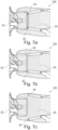
- Fig. 7a shows the hinge element 35 arrangement at a high mass flow rate of the compressor wheel 20
- Fig. 7b shows the hinge element 35 arrangement at a peak efficiency of the compressor wheel
- Fig. 7c shows the hinge element 35 arrangement at a low mass flow rate of the compressor wheel 20.
- the insert unit 30 further comprises a recirculation means 34 along a circumferential edge facing the compressor wheel 20 (see Fig. 5 ).
- the recirculation means 34 is arranged at an outer edge of the insert unit 30 facing the compressor wheel 20.
- the recirculation means 34 is configured to inhibit a backflow of the pressurized air from the compressor wheel 20.
- the recirculation means 34 is formed as a groove in a circumferential direction of the outer edge of the insert unit 30.
- the circumferential edge of the insert unit 30 facing the compressor wheel 20 may be inclined outwardly or inwardly relative to the rotation axis of the compressor wheel 20 to avoid the backflow of the pressurized air.
Landscapes
- Engineering & Computer Science (AREA)
- Mechanical Engineering (AREA)
- General Engineering & Computer Science (AREA)
- Chemical & Material Sciences (AREA)
- Combustion & Propulsion (AREA)
- Structures Of Non-Positive Displacement Pumps (AREA)
Claims (10)
- Ensemble turbocompresseur (100), comprenant :- un canal d'admission d'air (10),- une roue de compresseur (20),- une unité d'insertion (30) et- une unité d'actionnement (40),le canal d'admission d'air (10) étant configuré pour aspirer de l'air vers la roue de compresseur (20),la roue de compresseur (20) étant configurée pour tourner afin de comprimer l'air aspiré,l'unité d'insertion (30) étant disposée entre le canal d'admission d'air (10) et la roue de compresseur (20) et configurée pour commander un flux d'air vers la roue de compresseur (20),l'unité d'actionnement (40) étant reliée à l'unité d'insertion (30) et configurée pour déplacer l'unité d'insertion (30) au moins partiellement le long du canal d'admission d'air (10) parallèlement à un axe de rotation de la roue de compresseur,l'ensemble turbocompresseur (100) comprenant en outre un élément de transition (50) entre la roue de compresseur (20) et le canal d'admission d'air (10), l'unité d'insertion (30) étant mobile le long d'une surface intérieure de l'élément de transition (50), etl'élément de transition (50) comprenant une première partie d'extrémité (51) et une seconde partie d'extrémité (52), la première partie d'extrémité (51) faisant face à la roue de compresseur (20) et la seconde partie d'extrémité (52) faisant face au canal d'admission d'air (10), un diamètre intérieur de la première partie d'extrémité (51) étant plus petit qu'un diamètre intérieur de la seconde partie d'extrémité (52) de l'élément de transition (50),l'unité d'insertion (30) comprenant un moyen de guidage (31) faisant face à la roue de compresseur (20), le moyen de guidage (31) étant configuré pour induire un pré-tourbillonnement du flux d'air en amont de la roue de compresseur (20),le moyen de guidage (31) comprenant plusieurs éléments formant languettes (32), les éléments formant languettes (32) étant disposés autour de l'axe de rotation de la roue de compresseur (20) et sensiblement parallèles à l'axe de rotation de la roue de compresseur (20), etles éléments formant languettes (32) étant disposés de manière inclinée dans le sens de rotation de la roue de compresseur (20).
- Ensemble turbocompresseur (100) selon la revendication 1, l'unité d'actionnement (40) comprenant un actionneur linéaire (41) configuré pour déplacer linéairement l'unité d'insertion (30) parallèlement à un axe de rotation de la roue de compresseur (20).
- Ensemble turbocompresseur (100) selon la revendication 1 précédente, chacun des éléments formant languettes (32) comprenant une forme de nervure ou d'ailette en saillie vers l'intérieur du moyen de guidage (31).
- Ensemble turbocompresseur (100) selon la revendication 1 ou 3, les éléments formant languettes (32) étant disposés dans une position fermée si le moyen de guidage (31) est positionné de manière adjacente à la première partie d'extrémité (51) de l'élément de transition (50).
- Ensemble turbocompresseur (100) selon l'une quelconque des revendications 1, 3 et 4 précédentes, les éléments formant languettes (32) étant configurés pour s'ouvrir progressivement le long d'un mouvement de l'unité d'insertion (30) de la première partie d'extrémité (51) vers la seconde partie d'extrémité (52) de l'élément de transition (50).
- Ensemble turbocompresseur (100) selon l'une quelconque des revendications précédentes, l'unité d'insertion (30) comprenant au moins un élément formant charnière (35), l'élément formant charnière (35) étant relié à un élément formant ressort (13) disposé sur une paroi intérieure du canal d'admission d'air (10), l'élément formant ressort (13) étant configuré pour presser l'élément formant charnière (35) vers l'intérieur du canal d'admission d'air (10).
- Ensemble turbocompresseur (100) selon l'une quelconque des revendications précédentes, le canal d'admission d'air (10) comprenant au moins un élément de blocage (11) au niveau de la paroi intérieure, l'élément de blocage (11) étant configuré pour limiter le mouvement de l'unité d'insertion (30).
- Ensemble turbocompresseur (100) selon l'une quelconque des revendications précédentes, l'unité d'insertion (30) comprenant un moyen de recirculation (34) le long d'un bord circonférentiel faisant face à la roue de compresseur (20).
- Véhicule comprenant un ensemble turbocompresseur (100) selon l'une quelconque des revendications 1 à 8 précédentes.
- Procédé de fabrication d'un ensemble turbocompresseur (100), comprenant les étapes de :- disposer une unité d'insertion (30) entre un canal d'admission d'air (10) et une roue de compresseur (20),- relier une unité d'actionnement (40) à l'unité d'insertion (30),- fournir un élément de transition (50) entre la roue de compresseur (20) et le canal d'admission d'air (10),- disposer des éléments formant languettes (32) autour d'un axe de rotation de la roue de compresseur (20) et sensiblement parallèles à l'axe de rotation de la roue de compresseur (20), et- disposer les éléments formant languettes (32) de manière inclinée dans un sens de rotation de la roue de compresseur (20),le canal d'admission d'air (10) étant configuré pour aspirer de l'air vers la roue de compresseur (20),la roue de compresseur (20) étant configurée pour tourner afin de comprimer l'air aspiré,l'unité d'insertion (30) étant configurée pour commander un flux d'air vers la roue de compresseur (20),l'unité d'actionnement (40) étant configurée pour déplacer l'unité d'insertion (30) au moins partiellement le long du canal d'admission d'air (10) parallèlement à un axe de rotation de la roue de compresseur,l'unité d'insertion (30) étant mobile le long d'une surface intérieure de l'élément de transition (50), etl'élément de transition (50) comprenant une première partie d'extrémité (51) et une seconde partie d'extrémité (52), la première partie d'extrémité (51) faisant face à la roue de compresseur (20) et la seconde partie d'extrémité (52) faisant face au canal d'admission d'air (10), un diamètre intérieur de la première partie d'extrémité (51) étant plus petit qu'un diamètre intérieur de la seconde partie d'extrémité (52) de l'élément de transition (50)l'unité d'insertion (30) comprenant un moyen de guidage (31) faisant face à la roue de compresseur (20), le moyen de guidage (31) étant configuré pour induire un pré-tourbillonnement du flux d'air en amont de la roue de compresseur (20),le moyen de guidage (31) comprenant plusieurs éléments formant languettes (32).
Priority Applications (3)
| Application Number | Priority Date | Filing Date | Title |
|---|---|---|---|
| EP21179246.0A EP4105493B1 (fr) | 2021-06-14 | 2021-06-14 | Ensemble turbocompresseur |
| US17/837,184 US11781560B2 (en) | 2021-06-14 | 2022-06-10 | Turbo compressor assembly |
| CN202210677847.8A CN115539429A (zh) | 2021-06-14 | 2022-06-14 | 涡轮压缩机组件 |
Applications Claiming Priority (1)
| Application Number | Priority Date | Filing Date | Title |
|---|---|---|---|
| EP21179246.0A EP4105493B1 (fr) | 2021-06-14 | 2021-06-14 | Ensemble turbocompresseur |
Publications (2)
| Publication Number | Publication Date |
|---|---|
| EP4105493A1 EP4105493A1 (fr) | 2022-12-21 |
| EP4105493B1 true EP4105493B1 (fr) | 2025-05-21 |
Family
ID=76444322
Family Applications (1)
| Application Number | Title | Priority Date | Filing Date |
|---|---|---|---|
| EP21179246.0A Active EP4105493B1 (fr) | 2021-06-14 | 2021-06-14 | Ensemble turbocompresseur |
Country Status (3)
| Country | Link |
|---|---|
| US (1) | US11781560B2 (fr) |
| EP (1) | EP4105493B1 (fr) |
| CN (1) | CN115539429A (fr) |
Family Cites Families (10)
| Publication number | Priority date | Publication date | Assignee | Title |
|---|---|---|---|---|
| JPS56165796A (en) * | 1980-05-23 | 1981-12-19 | Nissan Motor Co Ltd | Turbo compressor |
| JPS5724496A (en) * | 1980-07-22 | 1982-02-09 | Nissan Motor Co Ltd | Turbo-compressor |
| DE60302542T8 (de) * | 2003-02-05 | 2007-03-29 | Borgwarner Inc., Auburn Hills | Dralldrossel für Radialverdichter |
| DE102004035044A1 (de) * | 2004-07-20 | 2006-03-09 | Daimlerchrysler Ag | Verdichter in einem Abgasturbolader für eine Brennkraftmaschine und Verfahren zum Betrieb eines Verdichters |
| DE102014006463A1 (de) * | 2014-05-06 | 2015-11-12 | Mann + Hummel Gmbh | Einstellbare Luftzufuhreinrichtung |
| US9932991B2 (en) * | 2016-04-04 | 2018-04-03 | Ford Global Technologies, Llc | Active swirl device for turbocharger compressor |
| DE102016217528A1 (de) * | 2016-09-14 | 2018-03-15 | Continental Automotive Gmbh | Turbolader für eine Brennkraftmaschine |
| US10851794B2 (en) * | 2017-12-05 | 2020-12-01 | Ford Global Technologies, Llc | Active casing treatment adapted with movable sleeve |
| US10502232B2 (en) * | 2018-03-01 | 2019-12-10 | Garrett Transportation I Inc. | Turbocharger compressor having adjustable trim mechanism including swirl inducers |
| GB2580759A (en) * | 2018-12-04 | 2020-07-29 | Borgwarner Inc | Variable inlet diameter unit |
-
2021
- 2021-06-14 EP EP21179246.0A patent/EP4105493B1/fr active Active
-
2022
- 2022-06-10 US US17/837,184 patent/US11781560B2/en active Active
- 2022-06-14 CN CN202210677847.8A patent/CN115539429A/zh active Pending
Also Published As
| Publication number | Publication date |
|---|---|
| US11781560B2 (en) | 2023-10-10 |
| US20220397054A1 (en) | 2022-12-15 |
| CN115539429A (zh) | 2022-12-30 |
| EP4105493A1 (fr) | 2022-12-21 |
Similar Documents
| Publication | Publication Date | Title |
|---|---|---|
| US7942625B2 (en) | Compressor and compressor housing | |
| CN1118638C (zh) | 用于内燃机的涡轮增压器 | |
| CN104428539B (zh) | 离心压缩机 | |
| US10550761B2 (en) | Turbocharger compressor having adjustable-trim mechanism | |
| US7628580B2 (en) | Variable geometry turbine | |
| US10544808B2 (en) | Turbocharger compressor having adjustable trim mechanism including vortex reducers | |
| CN104428509B (zh) | 离心压缩机 | |
| US10808569B2 (en) | Turbocharger | |
| US7874789B2 (en) | Compressor and compressor housing | |
| CN110219822A (zh) | 具有包括涡流导风轮的可调调整机构的涡轮增压器压缩机 | |
| US10883418B2 (en) | Turbocharger for an internal combustion engine | |
| CN101027491A (zh) | 带再循环的压缩机装置及其方法 | |
| US10697377B2 (en) | Turbine supercharger and two-stage supercharging system | |
| US9567942B1 (en) | Centrifugal turbomachines having extended performance ranges | |
| JP4719269B2 (ja) | 内燃機関用の排気ガスターボチャージャ | |
| EP4105493B1 (fr) | Ensemble turbocompresseur | |
| US10018164B2 (en) | Gas compressor pressure relief noise reduction | |
| US12372093B2 (en) | Centrifugal compressor and turbocharger | |
| US11761458B2 (en) | Compressor and turbocharger including compressor | |
| US20210372430A1 (en) | Centrifugal compressor | |
| US11187144B2 (en) | Diffuser and turbocharger | |
| CN221942820U (zh) | 用于压缩机的受控区域累进扩散器、压缩机以及涡轮增压器 | |
| CN113574281B (zh) | 离心压缩机以及涡轮增压器 | |
| GB2641420A (en) | Compressor | |
| JPS588279A (ja) | 回転羽根ポンプ |
Legal Events
| Date | Code | Title | Description |
|---|---|---|---|
| PUAI | Public reference made under article 153(3) epc to a published international application that has entered the european phase |
Free format text: ORIGINAL CODE: 0009012 |
|
| STAA | Information on the status of an ep patent application or granted ep patent |
Free format text: STATUS: REQUEST FOR EXAMINATION WAS MADE |
|
| 17P | Request for examination filed |
Effective date: 20220215 |
|
| AK | Designated contracting states |
Kind code of ref document: A1 Designated state(s): AL AT BE BG CH CY CZ DE DK EE ES FI FR GB GR HR HU IE IS IT LI LT LU LV MC MK MT NL NO PL PT RO RS SE SI SK SM TR |
|
| STAA | Information on the status of an ep patent application or granted ep patent |
Free format text: STATUS: EXAMINATION IS IN PROGRESS |
|
| 17Q | First examination report despatched |
Effective date: 20230504 |
|
| GRAP | Despatch of communication of intention to grant a patent |
Free format text: ORIGINAL CODE: EPIDOSNIGR1 |
|
| STAA | Information on the status of an ep patent application or granted ep patent |
Free format text: STATUS: GRANT OF PATENT IS INTENDED |
|
| INTG | Intention to grant announced |
Effective date: 20241220 |
|
| GRAS | Grant fee paid |
Free format text: ORIGINAL CODE: EPIDOSNIGR3 |
|
| GRAA | (expected) grant |
Free format text: ORIGINAL CODE: 0009210 |
|
| STAA | Information on the status of an ep patent application or granted ep patent |
Free format text: STATUS: THE PATENT HAS BEEN GRANTED |
|
| AK | Designated contracting states |
Kind code of ref document: B1 Designated state(s): AL AT BE BG CH CY CZ DE DK EE ES FI FR GB GR HR HU IE IS IT LI LT LU LV MC MK MT NL NO PL PT RO RS SE SI SK SM TR |
|
| REG | Reference to a national code |
Ref country code: GB Ref legal event code: FG4D |
|
| REG | Reference to a national code |
Ref country code: CH Ref legal event code: EP |
|
| P01 | Opt-out of the competence of the unified patent court (upc) registered |
Free format text: CASE NUMBER: APP_21576/2025 Effective date: 20250507 |
|
| REG | Reference to a national code |
Ref country code: DE Ref legal event code: R096 Ref document number: 602021031018 Country of ref document: DE |
|
| REG | Reference to a national code |
Ref country code: IE Ref legal event code: FG4D |
|
| PGFP | Annual fee paid to national office [announced via postgrant information from national office to epo] |
Ref country code: DE Payment date: 20250520 Year of fee payment: 5 |
|
| PGFP | Annual fee paid to national office [announced via postgrant information from national office to epo] |
Ref country code: GB Payment date: 20250619 Year of fee payment: 5 |
|
| PGFP | Annual fee paid to national office [announced via postgrant information from national office to epo] |
Ref country code: FR Payment date: 20250619 Year of fee payment: 5 |
|
| PGFP | Annual fee paid to national office [announced via postgrant information from national office to epo] |
Ref country code: AT Payment date: 20250721 Year of fee payment: 5 |
|
| REG | Reference to a national code |
Ref country code: NL Ref legal event code: MP Effective date: 20250521 |
|
| PG25 | Lapsed in a contracting state [announced via postgrant information from national office to epo] |
Ref country code: FI Free format text: LAPSE BECAUSE OF FAILURE TO SUBMIT A TRANSLATION OF THE DESCRIPTION OR TO PAY THE FEE WITHIN THE PRESCRIBED TIME-LIMIT Effective date: 20250521 Ref country code: PT Free format text: LAPSE BECAUSE OF FAILURE TO SUBMIT A TRANSLATION OF THE DESCRIPTION OR TO PAY THE FEE WITHIN THE PRESCRIBED TIME-LIMIT Effective date: 20250922 Ref country code: ES Free format text: LAPSE BECAUSE OF FAILURE TO SUBMIT A TRANSLATION OF THE DESCRIPTION OR TO PAY THE FEE WITHIN THE PRESCRIBED TIME-LIMIT Effective date: 20250521 |
|
| REG | Reference to a national code |
Ref country code: LT Ref legal event code: MG9D |
|
| PG25 | Lapsed in a contracting state [announced via postgrant information from national office to epo] |
Ref country code: NO Free format text: LAPSE BECAUSE OF FAILURE TO SUBMIT A TRANSLATION OF THE DESCRIPTION OR TO PAY THE FEE WITHIN THE PRESCRIBED TIME-LIMIT Effective date: 20250821 Ref country code: GR Free format text: LAPSE BECAUSE OF FAILURE TO SUBMIT A TRANSLATION OF THE DESCRIPTION OR TO PAY THE FEE WITHIN THE PRESCRIBED TIME-LIMIT Effective date: 20250822 |
|
| PG25 | Lapsed in a contracting state [announced via postgrant information from national office to epo] |
Ref country code: NL Free format text: LAPSE BECAUSE OF FAILURE TO SUBMIT A TRANSLATION OF THE DESCRIPTION OR TO PAY THE FEE WITHIN THE PRESCRIBED TIME-LIMIT Effective date: 20250521 Ref country code: PL Free format text: LAPSE BECAUSE OF FAILURE TO SUBMIT A TRANSLATION OF THE DESCRIPTION OR TO PAY THE FEE WITHIN THE PRESCRIBED TIME-LIMIT Effective date: 20250521 |
|
| PG25 | Lapsed in a contracting state [announced via postgrant information from national office to epo] |
Ref country code: BG Free format text: LAPSE BECAUSE OF FAILURE TO SUBMIT A TRANSLATION OF THE DESCRIPTION OR TO PAY THE FEE WITHIN THE PRESCRIBED TIME-LIMIT Effective date: 20250521 |
|
| PG25 | Lapsed in a contracting state [announced via postgrant information from national office to epo] |
Ref country code: HR Free format text: LAPSE BECAUSE OF FAILURE TO SUBMIT A TRANSLATION OF THE DESCRIPTION OR TO PAY THE FEE WITHIN THE PRESCRIBED TIME-LIMIT Effective date: 20250521 |
|
| PG25 | Lapsed in a contracting state [announced via postgrant information from national office to epo] |
Ref country code: RS Free format text: LAPSE BECAUSE OF FAILURE TO SUBMIT A TRANSLATION OF THE DESCRIPTION OR TO PAY THE FEE WITHIN THE PRESCRIBED TIME-LIMIT Effective date: 20250821 |
|
| PG25 | Lapsed in a contracting state [announced via postgrant information from national office to epo] |
Ref country code: IS Free format text: LAPSE BECAUSE OF FAILURE TO SUBMIT A TRANSLATION OF THE DESCRIPTION OR TO PAY THE FEE WITHIN THE PRESCRIBED TIME-LIMIT Effective date: 20250921 |
|
| PG25 | Lapsed in a contracting state [announced via postgrant information from national office to epo] |
Ref country code: LV Free format text: LAPSE BECAUSE OF FAILURE TO SUBMIT A TRANSLATION OF THE DESCRIPTION OR TO PAY THE FEE WITHIN THE PRESCRIBED TIME-LIMIT Effective date: 20250521 |
|
| REG | Reference to a national code |
Ref country code: AT Ref legal event code: MK05 Ref document number: 1796957 Country of ref document: AT Kind code of ref document: T Effective date: 20250521 |
|
| PG25 | Lapsed in a contracting state [announced via postgrant information from national office to epo] |
Ref country code: DK Free format text: LAPSE BECAUSE OF FAILURE TO SUBMIT A TRANSLATION OF THE DESCRIPTION OR TO PAY THE FEE WITHIN THE PRESCRIBED TIME-LIMIT Effective date: 20250521 Ref country code: AT Free format text: LAPSE BECAUSE OF FAILURE TO SUBMIT A TRANSLATION OF THE DESCRIPTION OR TO PAY THE FEE WITHIN THE PRESCRIBED TIME-LIMIT Effective date: 20250521 Ref country code: SM Free format text: LAPSE BECAUSE OF FAILURE TO SUBMIT A TRANSLATION OF THE DESCRIPTION OR TO PAY THE FEE WITHIN THE PRESCRIBED TIME-LIMIT Effective date: 20250521 |
|
| PG25 | Lapsed in a contracting state [announced via postgrant information from national office to epo] |
Ref country code: CZ Free format text: LAPSE BECAUSE OF FAILURE TO SUBMIT A TRANSLATION OF THE DESCRIPTION OR TO PAY THE FEE WITHIN THE PRESCRIBED TIME-LIMIT Effective date: 20250521 |
|
| PG25 | Lapsed in a contracting state [announced via postgrant information from national office to epo] |
Ref country code: EE Free format text: LAPSE BECAUSE OF FAILURE TO SUBMIT A TRANSLATION OF THE DESCRIPTION OR TO PAY THE FEE WITHIN THE PRESCRIBED TIME-LIMIT Effective date: 20250521 |
|
| PG25 | Lapsed in a contracting state [announced via postgrant information from national office to epo] |
Ref country code: SK Free format text: LAPSE BECAUSE OF FAILURE TO SUBMIT A TRANSLATION OF THE DESCRIPTION OR TO PAY THE FEE WITHIN THE PRESCRIBED TIME-LIMIT Effective date: 20250521 |
|
| REG | Reference to a national code |
Ref country code: CH Ref legal event code: H13 Free format text: ST27 STATUS EVENT CODE: U-0-0-H10-H13 (AS PROVIDED BY THE NATIONAL OFFICE) Effective date: 20260127 |
|
| PG25 | Lapsed in a contracting state [announced via postgrant information from national office to epo] |
Ref country code: IT Free format text: LAPSE BECAUSE OF FAILURE TO SUBMIT A TRANSLATION OF THE DESCRIPTION OR TO PAY THE FEE WITHIN THE PRESCRIBED TIME-LIMIT Effective date: 20250521 |
|
| PG25 | Lapsed in a contracting state [announced via postgrant information from national office to epo] |
Ref country code: LU Free format text: LAPSE BECAUSE OF NON-PAYMENT OF DUE FEES Effective date: 20250614 |
|
| PG25 | Lapsed in a contracting state [announced via postgrant information from national office to epo] |
Ref country code: MC Free format text: LAPSE BECAUSE OF FAILURE TO SUBMIT A TRANSLATION OF THE DESCRIPTION OR TO PAY THE FEE WITHIN THE PRESCRIBED TIME-LIMIT Effective date: 20250521 |
|
| REG | Reference to a national code |
Ref country code: DE Ref legal event code: R097 Ref document number: 602021031018 Country of ref document: DE |
|
| REG | Reference to a national code |
Ref country code: BE Ref legal event code: MM Effective date: 20250630 |
|
| PG25 | Lapsed in a contracting state [announced via postgrant information from national office to epo] |
Ref country code: RO Free format text: LAPSE BECAUSE OF FAILURE TO SUBMIT A TRANSLATION OF THE DESCRIPTION OR TO PAY THE FEE WITHIN THE PRESCRIBED TIME-LIMIT Effective date: 20250521 |
|
| PLBE | No opposition filed within time limit |
Free format text: ORIGINAL CODE: 0009261 |
|
| STAA | Information on the status of an ep patent application or granted ep patent |
Free format text: STATUS: NO OPPOSITION FILED WITHIN TIME LIMIT |
|
| REG | Reference to a national code |
Ref country code: CH Ref legal event code: L10 Free format text: ST27 STATUS EVENT CODE: U-0-0-L10-L00 (AS PROVIDED BY THE NATIONAL OFFICE) Effective date: 20260402 |
|
| PG25 | Lapsed in a contracting state [announced via postgrant information from national office to epo] |
Ref country code: IE Free format text: LAPSE BECAUSE OF NON-PAYMENT OF DUE FEES Effective date: 20250614 |
|
| PG25 | Lapsed in a contracting state [announced via postgrant information from national office to epo] |
Ref country code: BE Free format text: LAPSE BECAUSE OF NON-PAYMENT OF DUE FEES Effective date: 20250630 |