EP4105497B1 - Dispositif de maintien et son procédé d'application - Google Patents
Dispositif de maintien et son procédé d'application Download PDFInfo
- Publication number
- EP4105497B1 EP4105497B1 EP21180367.1A EP21180367A EP4105497B1 EP 4105497 B1 EP4105497 B1 EP 4105497B1 EP 21180367 A EP21180367 A EP 21180367A EP 4105497 B1 EP4105497 B1 EP 4105497B1
- Authority
- EP
- European Patent Office
- Prior art keywords
- holding device
- base body
- hood
- wall
- fastener
- Prior art date
- Legal status (The legal status is an assumption and is not a legal conclusion. Google has not performed a legal analysis and makes no representation as to the accuracy of the status listed.)
- Active
Links
Images
Classifications
-
- B—PERFORMING OPERATIONS; TRANSPORTING
- B64—AIRCRAFT; AVIATION; COSMONAUTICS
- B64C—AEROPLANES; HELICOPTERS
- B64C1/00—Fuselages; Constructional features common to fuselages, wings, stabilising surfaces or the like
- B64C1/06—Frames; Stringers; Longerons ; Fuselage sections
- B64C1/066—Interior liners
-
- F—MECHANICAL ENGINEERING; LIGHTING; HEATING; WEAPONS; BLASTING
- F16—ENGINEERING ELEMENTS AND UNITS; GENERAL MEASURES FOR PRODUCING AND MAINTAINING EFFECTIVE FUNCTIONING OF MACHINES OR INSTALLATIONS; THERMAL INSULATION IN GENERAL
- F16B—DEVICES FOR FASTENING OR SECURING CONSTRUCTIONAL ELEMENTS OR MACHINE PARTS TOGETHER, e.g. NAILS, BOLTS, CIRCLIPS, CLAMPS, CLIPS OR WEDGES; JOINTS OR JOINTING
- F16B37/00—Nuts or like thread-engaging members
- F16B37/04—Devices for fastening nuts to surfaces, e.g. sheets, plates
- F16B37/048—Non-releasable devices
-
- F—MECHANICAL ENGINEERING; LIGHTING; HEATING; WEAPONS; BLASTING
- F16—ENGINEERING ELEMENTS AND UNITS; GENERAL MEASURES FOR PRODUCING AND MAINTAINING EFFECTIVE FUNCTIONING OF MACHINES OR INSTALLATIONS; THERMAL INSULATION IN GENERAL
- F16B—DEVICES FOR FASTENING OR SECURING CONSTRUCTIONAL ELEMENTS OR MACHINE PARTS TOGETHER, e.g. NAILS, BOLTS, CIRCLIPS, CLAMPS, CLIPS OR WEDGES; JOINTS OR JOINTING
- F16B11/00—Connecting constructional elements or machine parts by sticking or pressing them together, e.g. cold pressure welding
- F16B11/006—Connecting constructional elements or machine parts by sticking or pressing them together, e.g. cold pressure welding by gluing
-
- F—MECHANICAL ENGINEERING; LIGHTING; HEATING; WEAPONS; BLASTING
- F16—ENGINEERING ELEMENTS AND UNITS; GENERAL MEASURES FOR PRODUCING AND MAINTAINING EFFECTIVE FUNCTIONING OF MACHINES OR INSTALLATIONS; THERMAL INSULATION IN GENERAL
- F16B—DEVICES FOR FASTENING OR SECURING CONSTRUCTIONAL ELEMENTS OR MACHINE PARTS TOGETHER, e.g. NAILS, BOLTS, CIRCLIPS, CLAMPS, CLIPS OR WEDGES; JOINTS OR JOINTING
- F16B37/00—Nuts or like thread-engaging members
- F16B37/04—Devices for fastening nuts to surfaces, e.g. sheets, plates
- F16B37/044—Nut cages
-
- F—MECHANICAL ENGINEERING; LIGHTING; HEATING; WEAPONS; BLASTING
- F16—ENGINEERING ELEMENTS AND UNITS; GENERAL MEASURES FOR PRODUCING AND MAINTAINING EFFECTIVE FUNCTIONING OF MACHINES OR INSTALLATIONS; THERMAL INSULATION IN GENERAL
- F16B—DEVICES FOR FASTENING OR SECURING CONSTRUCTIONAL ELEMENTS OR MACHINE PARTS TOGETHER, e.g. NAILS, BOLTS, CIRCLIPS, CLAMPS, CLIPS OR WEDGES; JOINTS OR JOINTING
- F16B41/00—Measures against loss of bolts, nuts, or pins; Measures against unauthorised operation of bolts, nuts or pins
- F16B41/002—Measures against loss of bolts, nuts or pins
-
- F—MECHANICAL ENGINEERING; LIGHTING; HEATING; WEAPONS; BLASTING
- F16—ENGINEERING ELEMENTS AND UNITS; GENERAL MEASURES FOR PRODUCING AND MAINTAINING EFFECTIVE FUNCTIONING OF MACHINES OR INSTALLATIONS; THERMAL INSULATION IN GENERAL
- F16B—DEVICES FOR FASTENING OR SECURING CONSTRUCTIONAL ELEMENTS OR MACHINE PARTS TOGETHER, e.g. NAILS, BOLTS, CIRCLIPS, CLAMPS, CLIPS OR WEDGES; JOINTS OR JOINTING
- F16B5/00—Joining sheets or plates, e.g. panels, to one another or to strips or bars parallel to them
- F16B5/02—Joining sheets or plates, e.g. panels, to one another or to strips or bars parallel to them by means of fastening members using screw-thread
- F16B5/0266—Joining sheets or plates, e.g. panels, to one another or to strips or bars parallel to them by means of fastening members using screw-thread using springs
-
- F—MECHANICAL ENGINEERING; LIGHTING; HEATING; WEAPONS; BLASTING
- F16—ENGINEERING ELEMENTS AND UNITS; GENERAL MEASURES FOR PRODUCING AND MAINTAINING EFFECTIVE FUNCTIONING OF MACHINES OR INSTALLATIONS; THERMAL INSULATION IN GENERAL
- F16B—DEVICES FOR FASTENING OR SECURING CONSTRUCTIONAL ELEMENTS OR MACHINE PARTS TOGETHER, e.g. NAILS, BOLTS, CIRCLIPS, CLAMPS, CLIPS OR WEDGES; JOINTS OR JOINTING
- F16B11/00—Connecting constructional elements or machine parts by sticking or pressing them together, e.g. cold pressure welding
-
- F—MECHANICAL ENGINEERING; LIGHTING; HEATING; WEAPONS; BLASTING
- F16—ENGINEERING ELEMENTS AND UNITS; GENERAL MEASURES FOR PRODUCING AND MAINTAINING EFFECTIVE FUNCTIONING OF MACHINES OR INSTALLATIONS; THERMAL INSULATION IN GENERAL
- F16B—DEVICES FOR FASTENING OR SECURING CONSTRUCTIONAL ELEMENTS OR MACHINE PARTS TOGETHER, e.g. NAILS, BOLTS, CIRCLIPS, CLAMPS, CLIPS OR WEDGES; JOINTS OR JOINTING
- F16B37/00—Nuts or like thread-engaging members
- F16B37/04—Devices for fastening nuts to surfaces, e.g. sheets, plates
- F16B37/041—Releasable devices
- F16B37/043—Releasable devices with snap action
-
- F—MECHANICAL ENGINEERING; LIGHTING; HEATING; WEAPONS; BLASTING
- F16—ENGINEERING ELEMENTS AND UNITS; GENERAL MEASURES FOR PRODUCING AND MAINTAINING EFFECTIVE FUNCTIONING OF MACHINES OR INSTALLATIONS; THERMAL INSULATION IN GENERAL
- F16B—DEVICES FOR FASTENING OR SECURING CONSTRUCTIONAL ELEMENTS OR MACHINE PARTS TOGETHER, e.g. NAILS, BOLTS, CIRCLIPS, CLAMPS, CLIPS OR WEDGES; JOINTS OR JOINTING
- F16B37/00—Nuts or like thread-engaging members
- F16B37/14—Cap nuts; Nut caps or bolt caps
-
- F—MECHANICAL ENGINEERING; LIGHTING; HEATING; WEAPONS; BLASTING
- F16—ENGINEERING ELEMENTS AND UNITS; GENERAL MEASURES FOR PRODUCING AND MAINTAINING EFFECTIVE FUNCTIONING OF MACHINES OR INSTALLATIONS; THERMAL INSULATION IN GENERAL
- F16B—DEVICES FOR FASTENING OR SECURING CONSTRUCTIONAL ELEMENTS OR MACHINE PARTS TOGETHER, e.g. NAILS, BOLTS, CIRCLIPS, CLAMPS, CLIPS OR WEDGES; JOINTS OR JOINTING
- F16B5/00—Joining sheets or plates, e.g. panels, to one another or to strips or bars parallel to them
- F16B5/01—Joining sheets or plates, e.g. panels, to one another or to strips or bars parallel to them by means of fastening elements specially adapted for honeycomb panels
Definitions
- Interior paneling is an important design element of the interior and also contributes to thermal and acoustic insulation. They are often designed as formwork without a load-bearing function and should therefore be as light as possible.
- wall elements made of sandwich panels with a honeycomb core.
- the materials used here are paper, aluminum or plastics (or composite materials of these). What these wall elements have in common is that their connection points with a load-bearing structure or the attachment of other elements to them can hardly be achieved using the known fastening methods such as screws, nails or spot bonding.
- a holding device or a holding cam is used to attach objects to a wall.
- the term wall or wall surface does not exclusively refer to a vertical, flat building surface, but rather to a general surface that would be colloquially referred to as a wall.
- Such a holding device therefore comprises a Base body, the underside of which should be the one facing the wall during installation and the top side should be the one facing away from the wall.
- the basic configuration is supplemented by a fastening arrangement and a hood that can be locked to the base body and arches over the fastening arrangement.
- the fastening arrangement represents the first half of a force- and/or form-fitting interface. It comprises a fastener and other application-specific components and is explained later.
- the base body has a central opening that defines a central axis that is perpendicular to the base body.
- a counter fastener later passes through this central opening, which is designed to be complementary to the fastener that is at least connected to the base body.
- the fastener connected to the base body in the fastening arrangement can be a threaded element (screw, threaded bolt), a nut (also cap nut), a snap fastener or a clamping element (e.g. a sleeve).
- the fastening arrangement is preferably connected to the base body in a captive and optionally twist-proof manner. "Connected” includes welded, glued or mechanically held (secured, pressed on, locked, clamped) or combinations thereof or technical equivalents.
- the base body has a circular ring-shaped surface on its underside that is arranged symmetrically to the central axis; in other words, it surrounds the central opening in a ring.
- a closed, circumferential web is attached to the inner and outer edges of this circular ring surface.
- the web on the inner edge is higher than the web on the outer edge, relative to the plane of the circular ring surface. This allows the web on the inner edge to be designed as a centering device, which facilitates the precise, central arrangement around the hole provided in a wall opening (for the counter fastener).
- the base body has at least two (further) through-openings in the circular ring surface, between the top and bottom.
- the connecting line between the positions of the two through-openings ideally intersects the center axis. Geometrically, this means that these openings are preferably arranged offset by 180° on the circular ring surface.
- This design results in a ring-shaped channel on the underside of the base body, laterally limited by the webs described.
- the two openings allow access to this ring-shaped channel from the top of the base body, even if the underside rests on a flat base because the two prescribed webs on the outer and inner edges define a distance between the circular ring surface and the base.
- the web on the inner edge of the circular ring surface is provided with a closed ring-shaped adhesive strip.
- This adhesive strip has the primary task of fixing the base body or the holding device in a desired position on the wall surface and also to allow a certain sealing effect to the central opening.
- a (counter) fastening element will later be guided through the wall element and the central opening into the fastener (stored in the fastening arrangement); therefore, any impairment of the free passage is disadvantageous.
- the adhesive track can be implemented as an adhesive application or as a double-sided adhesive tape.
- the adhesive effect can also only be achieved through the contact pressure during assembly, for example.
- the adhesive track can also be implemented on the outer ring or on both.
- a preferred design is when the web on the inner edge of the circular ring surface is made higher. Higher means that the web protrudes further from the plane of the circular ring surface than the web on the outer edge. This creates a better seal in the center. This can be achieved with a difference of less than one millimeter. If the difference is chosen to be significantly larger, the inner edge can be used as a centering device for the wall opening, thus making the assembly process easier. To do this, a pilot hole (or its diameter) can be designed in the base so that the inner edge rests on the edge of the hole.
- the circular ring surface mentioned above can be designed as a flat surface with rectangular or inclined inner/outer edge webs.
- an oval, barrel-shaped curvature in cross-section is also conceivable, which helps to increase the volume of the circular ring-shaped channel.
- the webs can be shaped so that they can be placed flush on a concave or convex surface instead of a flat surface.
- the holding device basically comprises a base body, a fastening arrangement and a hood.
- the fastening arrangement is an assembly of at least one fastener and a hollow cylindrical or sleeve-shaped centering cap.
- the centering cap has the task of holding the fastener in a predetermined position relative to the base body, while the hood in turn represents a securing element that fixes the fastening arrangement in the base body.
- Possible fasteners in the fastening arrangement are: threaded elements, nuts, cap nuts, snap fasteners, clamp(s) or locking elements.
- the centering cap has a first and a second longitudinal end. It is designed to be connected to the fastener and then essentially along its longitudinal axis. For this purpose, it has a holding device for the fastener at the first longitudinal end and an opening at the second longitudinal end that allows access to the inside of the centering cap.
- the fastener if designed as a screw, is held at one end, e.g. at the screw head, and the screw shaft is arranged along the central longitudinal axis of the centering cap.
- the shaft is surrounded on all sides by the sleeve at a distance.
- the sleeve end is accessible at the second longitudinal end so that, when installed, the counter-fastener can engage with the fastener.
- the centering cap is preferably designed in such a way that it can be arranged in the base body in a way that prevents it from twisting.
- centering lugs pointing radially outwards are provided on its second longitudinal end in order to engage in correspondingly shaped centering grooves in the base body.
- Correspondingly shaped here means a technical principle such as a key lock or tongue and groove or technical equivalents. In this way, for example, a positive connection can be achieved between the base body and the centering cap, which ensures that the base body and the centering cap are secured against twisting.
- This connection between the base body and the centering cap is preferably designed to be detachable.
- a one-piece, circular retaining ring can be provided, which is arranged symmetrically to the center axis.
- the retaining ring can act as a type of cage, which, in addition to the centering lugs, prevents the connected fastening element of the holding device from slipping.
- the hood mentioned above is essentially bell-shaped or pot-shaped.
- the single access opening into the interior of the hood is therefore provided with an edge area.
- the hood is now shaped and dimensioned in such a way that it can be positively locked to the retaining ring.
- the hood can be put over the retaining ring or inserted centrally into it and fixed there.
- Locking elements are provided to enable the above-mentioned safety function of the hood, namely to fix the fastening arrangement in or on the base body or retaining ring. These are preferably provided on the retaining ring as well as on the hood (in particular on the edge area), so that through their interaction the hood and retaining ring (or the base body) can be fixed in a defined end position in a detachable or non-detachable manner.
- the locking elements between the hood and the retaining ring can include: threads, locking elements, clamping elements, adhesives as well as technically useful combinations and technical equivalents.
- a holding device as described above can be made of metal or plastic or as a combination of plastic and metal components.
- Thermoplastics or polymers that can be used in injection molding processes are particularly suitable as plastics.
- the base body can preferably be made of transparent or semi-transparent plastic.
- the circular channel serves as an adhesive reservoir and adhesive connection.
- a (semi-)transparent design allows for visual inspection of whether the channel is completely filled and free of bubbles.
- the hood can have a predetermined dividing line along which the hood can be separated or broken open. This can be achieved by a slot-shaped dividing line that is bridged by connecting elements. These connecting elements are broken open by a suitable tool under the application of force so that the hood breaks open into two or more parts. If you look at the whole thing in the assembled state, this means that the centering cap is exposed and can be removed from the base body (if the connection is detachable). This makes it possible to detach the fastening arrangement from the base body after removing the counter-fastener.
- a defective counter-fastener (damaged thread) can be replaced and at the same time a new fastening arrangement can be used to replace it with an equivalent pull-out force without having to change the base body or the existing hole. If the hood and base body are connected to one another using snap/locking fasteners, this replacement can even be carried out largely without tools.
- the dimensioning of a holding device as described follows the technical requirements of the planned application.
- the diameter of the base body and thus also the size and volume of the circular adhesive channel is determined based on the wall structure and the forces that the holding device has to absorb.
- a base body with a large diameter allows the surface pressure (for a given load) to be reduced.
- the channel on the underside can of course only be designed as wide as necessary to achieve the desired holding effect.
- the dimensioning of the fastening arrangement can be determined accordingly based on the fastener to be used, its length and diameter. A specialist can implement this design using his specialist knowledge.
- a method for attaching a holding device as described above comprises the following steps: Providing a wall element with an opening into which the holding device is to be inserted. A holding device that is also provided, more precisely the underside of the base body, is pressed or attached to the wall, with the central opening of the base body being arranged concentrically with the wall opening. Attaching means gluing using an adhesive ring or a temporary mechanical fastening (holder).
- an adhesive is poured or injected into the circular channel through the first of the two through openings from the top of the base body.
- This can be done using a glue gun, a tube or a syringe.
- the adhesive will spread along the circular channel on the underside, with the second opening serving as a vent. Because it is arranged 180° offset on the circular ring, the plastic figuratively flows around the central opening, guided by the circularly arranged webs on the underside, until the adhesive reaches the vent opening and exits there. This allows the success of the bond to be visually checked. If a transparent plastic is used for the base body, the fill level can be estimated and the amount of adhesive can be precisely metered.
- the adhesive then hardens.
- the specialist will choose a suitable adhesive depending on the application and the material of the base body and wall.
- the viscosity is adjusted to the dimensions of the through holes or the circular channel.
- Two-component adhesives can be used, which are mixed immediately when injected. Air-curing adhesives, fast-curing adhesives or adhesives whose activators are provided as a coating in the circular adhesive channel, for example, are also conceivable.
- the holding device After curing, the holding device can be used as intended.
- the holding device according to the invention is (usually) mounted on the back of a wall, to the front of which an object is to be attached.
- the anchoring is therefore carried out by the object and the holding device clamping the wall in between.
- the counter fastener mentioned above is guided from the front through the second end of a through-hole or bore in the wall, at the rear (first) end of which the holding device as described above.
- the counter-fastener engages the fastening arrangement in a force-fitting or form-fitting, clamping, latching or locking manner.
- a holding arrangement therefore comprises a holding device and a counter-fastener.
- the method described has the advantage for the lightweight walls mentioned at the beginning that the force is not introduced into the volume of the wall as in a classic screw connection and no filling of the hollow chambers is required to create an anchoring base.
- the method described can be easily adapted to walls of different thicknesses by selecting an appropriate length of the counter fastener.
- front and back is not intended to be limiting, but refers to the most common application. If the holding device according to the invention is designed to be aesthetically pleasing, it can also be used, for example, to avoid being a nuisance on a partition wall that is accessible from both sides.
- the described assembly of the holding device can be carried out as a whole or by first gluing only the base body. This also allows a better visual inspection of the bonding and any adhesive that may leak into the central hole can be removed. In addition, depending on the installation position, it may be better to glue the lightest possible component first.
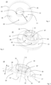
- Figure 1 considers a base body 10 in a conventional design with its essential features.
- the underside 11 has a circular ring surface 20 with a central opening 14.
- the inner boundary is formed by the web 22 on the inner edge.
- the outer edge is represented by a circular, closed, circumferential web 24.
- the webs and the circular ring surface thus form a type of flat, circular ring-shaped channel or adhesive channel 25.
- the two through openings 26 and 28 that connect this channel to the upper side 12 of the base body 10 can be seen.
- Figure 2 shows the base body 10 from Figure 1 viewed from its top 12.
- the comparison with Figure 1 shows the position of the through openings 26 and 28, they are colloquially arranged "opposite each other" on the circular ring or on a common connecting line 17 with the central opening 14.
- Figure 2 shows the retaining ring 30 on the top side, which, when placed on the top side 12, forms a radial boundary, similar to a pot. If the base body 10 is glued to a wall surface, it offers a receptacle for a fastening arrangement and a hood (in Figure 2 omitted). Basically, the base body 10 thus fulfils the function of a load distribution disc on the one hand and a fastening interface on the other.
- two locking elements 32 are embedded in the retaining ring in the form of openings through the ring wall. These serve, as shown in the overview of Figure 7 and 8 becomes clear, the accommodation of locking lugs (locking elements 42) which are attached to the edge area 48 of the hood.
- insertion aids 18 are provided, which are designed here as short, inward-facing ramps.
- Figure 3 shows the functionality and division of the functional areas just discussed in cross-section. It is clearly visible how the webs 22 and 24 protruding from the underside 11 form the adhesive channel 25 between themselves and the circular surface 20.
- the variant shown is one in which the web 22 on the inner edge is higher than the one on the outer edge 24. This allows the base body to be centered on or in a drill hole. The center axis 15 of the base body as well as of the inner edge web 22 would then coincide with the center axis of the drill opening.
- the Figures 4 and 6 show details of the fastening arrangement 50, whereby Figure 4 only the centering cap 58 is omitted.
- the fastener 52 shown here is a screw which is held in the centering cap 58 via a circumferential groove 51 as a holding device at the first longitudinal end 61. It can be installed in a twist-proof manner, e.g. with the help of a retaining lug 53.
- a spiral spring 54 is located in the space between the centering cap and the shaft of the screw. This is supported on the one hand on the underside of the screw head and on the other hand on a combination of support disk 56 and locking disk 57. The latter also has a pin-shaped anti-twist device.
- the screw (feature 52) is installed here in such a way that it is surrounded in the shaft area by the combination of support disk and locking disk in a circular ring and can - in principle - be moved along the longitudinal axis of the screw.
- the centering cap 58 At the lower end of the centering cap 58 (second longitudinal end 62) the centering cap is open (opening 59).
- the counter-fastener to this screw 52 shown would in this case be a nut or cap nut. If the threads of the screw and nut engage during the setting process, then - with regard to Figure 6 - move the nut towards the screw head. It then hits the support disk 56 and presses this against the locking disk 57 and the spiral spring 54. The rotation of the nut relative to the screw is absorbed by the locking disk 57, which, in conjunction with the spiral spring, ensures that the screw connection cannot be reversed.
- the advantage of the quasi-modular design of the holding device is that the base body can be used for a variety of fasteners or fastening arrangements, which reduces the complexity of storage and assembly. Another advantage is the ability to release and replace the connection (depending on the selected configuration as described above).
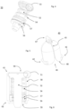
- FIG. 5 shows a hood 40 in a first embodiment, which is designed to be inserted into the Figure 7 shown retaining ring 30.
- the hood has locking elements 42 on the edge area 48, which are designed to complement the elements 32.
- the hood 40 has a desired dividing line 45, which is designed here as a dividing gap and runs over the top of the hood.
- the two halves are held together by a connecting element 47, which is designed here as a tab in the form of a loop. This shape was chosen because it makes it easy to remove the tab with a side cutter or a knife and thus divide the hood.
- the dividing line 45 runs into an arched widening towards the edge area 48 or the opening 46. This notch makes it easier to remove the hood halves from the retaining ring 30.
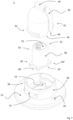
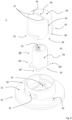
- FIGS. 7 and 8 show a combination of base body 10, fastening arrangement 50 and two differently designed hoods 40. These elements are drawn apart in the illustration along their longitudinal axis / assembly axis. With regard to the basic functionality and elements, reference is made to the sections above. It should be emphasized that in these drawings the intended engagement of the centering lugs 60 on the second longitudinal end 62 of the centering cap 58 with the centering grooves 16 in the base body 10 is shown. The hood 40 then encloses the fastening arrangement during assembly; the locking elements 42 of the hood 40 slide along the insertion aids 18 into the retaining ring 30 to engage in the locking elements 32 there.
- the hood 40 of Figure 8 differs in design from that in the Figures 5 and 8
- the outer shape is based on a cylinder
- the locking elements 42 on the edge area 48 are identical to the design in Figure 7
- the dividing line 45 divides the hood into two halves, which are held together by two connecting elements 47. The halves can be separated by levering them open with a screwdriver blade via the slot 49.
Landscapes
- Engineering & Computer Science (AREA)
- General Engineering & Computer Science (AREA)
- Mechanical Engineering (AREA)
- Aviation & Aerospace Engineering (AREA)
- Connection Of Plates (AREA)
Claims (17)
- Dispositif de maintien (1) pour placer des objets sur la surface d'une paroi, comprenant un corps de base (10), un dispositif de fixation (50) et un couvercle (40) qui peut être verrouillé avec le corps de base (10) et s'incurve par-dessus le dispositif de fixation (50), dans lequelle corps de base (10) comporte une face inférieure (11) tournée vers la surface de paroi lors du montage et une face supérieure (12) tournée à l'opposé de la paroi, ainsi qu'une ouverture centrale (14) entre la face supérieure et la face inférieure, qui définit un axe médian (15) perpendiculaire au corps de base (10), et le corps de base (10) comporte sur sa face inférieure (11) une surface en forme d'anneau circulaire (20) qui est disposée de façon symétrique autour de l'axe médian (15),une barrette (22, 24), fermée et dépassant de la face inférieure (11), est disposée sur sa périphérie, respectivement sur le bord intérieur et sur le bord extérieur,et au moins deux ouvertures de passage (26, 28) sont prévues dans la surface en forme d'anneau circulaire (20) entre la face supérieure (12) et la face inférieure (11),caractérisé en ce que la barrette (22) est plus haute sur le bord intérieur de la surface en forme d'anneau circulaire, par rapport au plan de la surface en forme d'anneau circulaire (20), que la barrette (24) du bord extérieur.
- Dispositif de maintien selon la revendication 1, caractérisé en ce qu'une ligne de liaison (17) entre les deux ouvertures de passage (26, 28) coupe l'axe médian (15).
- Dispositif de maintien selon la revendication 1-2, caractérisé en ce que la barrette du bord intérieur (22) et/ou celle du bord extérieur (24) de la surface en forme d'anneau circulaire (20) forment chacune une piste de collage annulaire fermée.
- Dispositif de maintien selon la revendication 1-3, caractérisé en ce que la barrette du bord intérieur (22) est conformée comme un dispositif de centrage pour disposer un perçage.
- Dispositif de maintien selon la revendication 1-4, caractérisé en ce que le dispositif de fixation (50) comprend une fixation (52) et un capuchon de centrage (58) en forme de cylindre creux ou de douille avec une première extrémité longitudinale (61) et une deuxième (62), le capuchon de centrage (58) étant conçu pour pouvoir être assemblé avec la fixation (52) et entourer pour l'essentiel celle-ci le long de son axe longitudinal.
- Dispositif de maintien selon la revendication 5, caractérisé en ce que le capuchon de centrage (58) comporte à sa première extrémité longitudinale (61) un dispositif de maintien (51) pour la fixation (52) et à sa deuxième extrémité longitudinale (62) une ouverture (59) qui donne accès à l'intérieur du capuchon de centrage (58).
- Dispositif de maintien selon les revendication 5 et 6, caractérisé en ce que le capuchon de centrage (58) comporte sur sa deuxième extrémité longitudinale (62) des ergots de centrage (60, 60', 60",...) orientés vers l'extérieur dans le sens radial, qui sont conçus pour s'engager dans des rainures de centrage (16, 16',...) de forme correspondante du corps de base (10) et empêcher ainsi une rotation entre le corps de base (10) et le capuchon de centrage (58).
- Dispositif de maintien selon les revendications 1-7, caractérisé en ce qu'est en outre disposé sur la face supérieure (12) du corps de base (10) un anneau de maintien (30) cylindrique formé dessus d'une pièce, qui est disposé de façon symétrique par rapport à l'axe médian (15).
- Dispositif de maintien selon la revendication 8, caractérisé en ce que le couvercle (40) est sensiblement en forme de cloche ou de pot avec une ouverture d'accès (46) unique dotée d'une zone de bord (48), le couvercle (40) étant conformé et dimensionné de telle façon que le couvercle (40) peut être verrouillé par engagement positif avec la bague de maintien (30).
- Dispositif de maintien selon la revendication 9, caractérisé en ce que des éléments de verrouillage (32, 42) sont disposés aussi bien sur la bague de maintien (30) que sur le couvercle (40) et peuvent interagir ensemble pour fixer le couvercle (40) et la bague de maintien (30) dans une position finale définie l'un par rapport à l'autre, d'une manière pouvant ou non être défaite.
- Dispositif de maintien (1) selon la revendication 10, caractérisé en ce que les éléments de verrouillage sont issus d'un groupe composé de : filetage, éléments d'enclenchement, éléments de serrage, adhésif.
- Dispositif de maintien (1) selon les revendications 1-11, caractérisé en ce que le dispositif de maintien (1) est fait de métal ou de plastique, en particulier d'un thermoplastique, ou d'une combinaison de pièces en plastique et en métal.
- Dispositif de maintien selon les revendications 1-12, caractérisé en ce que la fixation (52) est issue d'un groupe composé de : élément fileté, écrou, écrou chapeau, fermeture enclenchée, serrage.
- Dispositif de maintien (1) selon les revendications 1-13, caractérisé en ce que le couvercle (40) comporte au moins une ligne de découpe (45) le long de laquelle le couvercle (40) peut être découpé, au moins un élément de liaison (47) étant prévu pour franchir la ligne de découpe (45) et la relier mécaniquement.
- Disposition de maintien comprenant un dispositif de maintien selon les revendications 1-14 ainsi qu'une fixation opposée à mettre en prise dans le dispositif de fixation (50), dans laquelle le dispositif de maintien (1) est centré sur son ouverture médiane (14) autour de la première extrémité d'un perçage traversant d'une paroi et la fixation opposée est introduite dans la disposition de maintien à travers la paroi par la deuxième extrémité du perçage traversant et s'y met en prise dans le dispositif de fixation par friction ou engagement positif, serrage, enclenchement ou verrouillage.
- Procédé pour la mise en place d'un dispositif de maintien selon les revendications 1 à 14, comprenant les étapes suivantes :- préparation d'un élément de paroi muni d'une ouverture ;- pressage ou application du corps de base (10) par sa face inférieure (11) sur la paroi, l'ouverture médiane (14) du corps de base (10) étant disposée de façon concentrique par rapport à l'ouverture de la paroi ;- remplissage ou injection d'un adhésif à travers la première des deux ouvertures de passage (26) sur la face supérieure (12) du corps de base (10),- jusqu'à ce que l'adhésif sorte par la deuxième ouverture de passage (28) sur la face supérieure (12) du corps de base (10).
- Procédé selon la revendication 16 pour la mise en place d'un dispositif de maintien selon la revendication 3 ou 4, caractérisé en ce que le pressage ou l'application est réalisé par application du corps de base au moyen des barrettes (22, 24) sur la face inférieure (11) du corps de base (10) et est produit par les pistes de collage appliquées sur la ou les barrettes.
Priority Applications (4)
| Application Number | Priority Date | Filing Date | Title |
|---|---|---|---|
| ES21180367T ES2992938T3 (en) | 2021-06-18 | 2021-06-18 | Holder device and method for its attachment |
| EP21180367.1A EP4105497B1 (fr) | 2021-06-18 | 2021-06-18 | Dispositif de maintien et son procédé d'application |
| CN202210679898.4A CN115489714A (zh) | 2021-06-18 | 2022-06-16 | 保持装置及其安装方法 |
| US17/844,135 US12066043B2 (en) | 2021-06-18 | 2022-06-20 | Holding device and method for attaching same |
Applications Claiming Priority (1)
| Application Number | Priority Date | Filing Date | Title |
|---|---|---|---|
| EP21180367.1A EP4105497B1 (fr) | 2021-06-18 | 2021-06-18 | Dispositif de maintien et son procédé d'application |
Publications (2)
| Publication Number | Publication Date |
|---|---|
| EP4105497A1 EP4105497A1 (fr) | 2022-12-21 |
| EP4105497B1 true EP4105497B1 (fr) | 2024-08-14 |
Family
ID=76999555
Family Applications (1)
| Application Number | Title | Priority Date | Filing Date |
|---|---|---|---|
| EP21180367.1A Active EP4105497B1 (fr) | 2021-06-18 | 2021-06-18 | Dispositif de maintien et son procédé d'application |
Country Status (4)
| Country | Link |
|---|---|
| US (1) | US12066043B2 (fr) |
| EP (1) | EP4105497B1 (fr) |
| CN (1) | CN115489714A (fr) |
| ES (1) | ES2992938T3 (fr) |
Families Citing this family (3)
| Publication number | Priority date | Publication date | Assignee | Title |
|---|---|---|---|---|
| WO2022046509A1 (fr) | 2020-08-27 | 2022-03-03 | Colder Products Company | Couplages fluidiques |
| DE202021103982U1 (de) * | 2021-07-26 | 2022-10-27 | Ehni Schaumstofftechnik Gmbh | Befestigeranordnung |
| IT202300026823A1 (it) * | 2023-12-15 | 2025-06-15 | Mosaiko Project S R L | Dispositivo di fissaggio per fissare un telo a un supporto e struttura telonata che lo comprende |
Family Cites Families (11)
| Publication number | Priority date | Publication date | Assignee | Title |
|---|---|---|---|---|
| US4295766A (en) * | 1978-07-27 | 1981-10-20 | Francis Shaw | Self-aligning dome nut |
| US20020162925A1 (en) * | 2001-05-07 | 2002-11-07 | Robin Song | Wall attachment display apparatus |
| US20060249638A1 (en) * | 2005-05-03 | 2006-11-09 | Jim Ehrke | Removably attachable shower bar |
| DE202006003557U1 (de) | 2006-03-03 | 2006-05-11 | Roman Dietsche Gmbh & Co. Kg | Befestigungs-Vorrichtung |
| US7922432B2 (en) * | 2008-12-03 | 2011-04-12 | Hanwit Precision Industries Ltd. | Quick-positioning screw assembly |
| US20110070049A1 (en) * | 2009-09-24 | 2011-03-24 | Kuo-Chung Wang | Fastener |
| US8382412B2 (en) * | 2010-04-09 | 2013-02-26 | Jeffrey Stuart Swanson | Apparatus for fastening single and multiple sheets and method for using same |
| US20120224935A1 (en) * | 2011-03-04 | 2012-09-06 | Ming-Chung Chiu | Floating fastener |
| DE102012107944A1 (de) | 2012-08-29 | 2014-03-06 | Rehau Ag + Co | Verfahren zur Herstellung einer Verbindung zwischen zwei Bauteilen, insbesondere Kfz-Bauteilen, sowie Verbindungselement |
| TWM449183U (zh) * | 2012-10-11 | 2013-03-21 | Hanwit Prec Ind Ltd | 板對板快速定位裝置 |
| DE202016106073U1 (de) * | 2016-10-28 | 2016-11-07 | Wenko-Wenselaar Gmbh & Co. Kg | Montagesystem mit integrierter Reservoirkupplung für Stoffschluss |
-
2021
- 2021-06-18 EP EP21180367.1A patent/EP4105497B1/fr active Active
- 2021-06-18 ES ES21180367T patent/ES2992938T3/es active Active
-
2022
- 2022-06-16 CN CN202210679898.4A patent/CN115489714A/zh active Pending
- 2022-06-20 US US17/844,135 patent/US12066043B2/en active Active
Also Published As
| Publication number | Publication date |
|---|---|
| EP4105497A1 (fr) | 2022-12-21 |
| US12066043B2 (en) | 2024-08-20 |
| US20220403867A1 (en) | 2022-12-22 |
| CN115489714A (zh) | 2022-12-20 |
| ES2992938T3 (en) | 2024-12-19 |
Similar Documents
| Publication | Publication Date | Title |
|---|---|---|
| EP1440246B1 (fr) | Systeme de montage servant a l'application d'elements de fixation sur une paroi | |
| EP4105497B1 (fr) | Dispositif de maintien et son procédé d'application | |
| DE4107790C1 (fr) | ||
| EP3114359B1 (fr) | Dispositif servant à assembler un élément de structure à un élément de maintien selon un espacement l'un par rapport à l'autre | |
| EP1454071A1 (fr) | Ecrou de raccordement concu pour visser des elements de construction sur un composant de type plaque | |
| DE19930728A1 (de) | Dübel für Flachmaterial | |
| EP1070003A2 (fr) | Dispositif de fixation de revetements interieurs destine a des vehicules | |
| DE2750829C2 (de) | Vorrichtung zum Einsetzen und Vergießen eines in einer Leichtbau-Schichtverbundplatte mit Vergußmasse zu befestigenden Gewindedübels o.dgl. | |
| WO2022008262A1 (fr) | Dispositif de retenue dans du ciment du type douille à multiples parties | |
| EP0919733A2 (fr) | Cheville de fixation pour éléments de garniture pour meubles | |
| EP3543089A1 (fr) | Dispositif de renforcement, d'étanchéité ou d'amortissement d'un élément structural | |
| DE102015114238A1 (de) | Anbindungssystem und Verfahren zur Befestigung eines Bauteils an einer Fahrzeugkarosserie | |
| DE3022414A1 (de) | Duebel fuer eine formschluessige verankerung in leichtbauwerkstoffen | |
| EP1394420B1 (fr) | Pièce à insérer dans une paroi, en particulier dans une carrosserie de véhicule | |
| DE3114283A1 (de) | "befestigungselement aus kunststoff, insbesondere zur loesbaren befestigung von flachen werkstuecken" | |
| DE19914189A1 (de) | Verbindungsvorrichtung | |
| EP1367267A1 (fr) | Douille sous forme de manchon | |
| EP1342041A1 (fr) | Procede de fixation d'un corps sur une paroi, avec etancheite assuree par une mousse | |
| EP2775083B1 (fr) | Assemblage de fixation, utilisation d'un dispositif et procédé de fixation d'un corps de bâtiment dans une ouverture limitée par une surface d'appui | |
| DE4217908C1 (en) | Spectacle lens fastener system - includes screw with tapered head expanding end of frame member fitting into bore in lens | |
| DE102008005489A1 (de) | Befestigungshülse | |
| DE20001437U1 (de) | Befestigungsvorrichtung für Sandwichplatte | |
| DE19647209C2 (de) | Befestigungsvorrichtung aus Kunststoff | |
| DE19502460C2 (de) | Klippbefestigung für Schreib-, Zeichen- oder Malgeräte sowie Verfahren zu deren Herstellung | |
| DE10249275B4 (de) | Befestigungsclip zum Verbinden zweier Teile |
Legal Events
| Date | Code | Title | Description |
|---|---|---|---|
| PUAI | Public reference made under article 153(3) epc to a published international application that has entered the european phase |
Free format text: ORIGINAL CODE: 0009012 |
|
| STAA | Information on the status of an ep patent application or granted ep patent |
Free format text: STATUS: THE APPLICATION HAS BEEN PUBLISHED |
|
| AK | Designated contracting states |
Kind code of ref document: A1 Designated state(s): AL AT BE BG CH CY CZ DE DK EE ES FI FR GB GR HR HU IE IS IT LI LT LU LV MC MK MT NL NO PL PT RO RS SE SI SK SM TR |
|
| STAA | Information on the status of an ep patent application or granted ep patent |
Free format text: STATUS: REQUEST FOR EXAMINATION WAS MADE |
|
| 17P | Request for examination filed |
Effective date: 20230621 |
|
| RBV | Designated contracting states (corrected) |
Designated state(s): AL AT BE BG CH CY CZ DE DK EE ES FI FR GB GR HR HU IE IS IT LI LT LU LV MC MK MT NL NO PL PT RO RS SE SI SK SM TR |
|
| GRAP | Despatch of communication of intention to grant a patent |
Free format text: ORIGINAL CODE: EPIDOSNIGR1 |
|
| STAA | Information on the status of an ep patent application or granted ep patent |
Free format text: STATUS: GRANT OF PATENT IS INTENDED |
|
| INTG | Intention to grant announced |
Effective date: 20240507 |
|
| RIN1 | Information on inventor provided before grant (corrected) |
Inventor name: HEINEKE, KAI Inventor name: ROTTLER, MARKUS |
|
| GRAS | Grant fee paid |
Free format text: ORIGINAL CODE: EPIDOSNIGR3 |
|
| GRAA | (expected) grant |
Free format text: ORIGINAL CODE: 0009210 |
|
| STAA | Information on the status of an ep patent application or granted ep patent |
Free format text: STATUS: THE PATENT HAS BEEN GRANTED |
|
| AK | Designated contracting states |
Kind code of ref document: B1 Designated state(s): AL AT BE BG CH CY CZ DE DK EE ES FI FR GB GR HR HU IE IS IT LI LT LU LV MC MK MT NL NO PL PT RO RS SE SI SK SM TR |
|
| REG | Reference to a national code |
Ref country code: GB Ref legal event code: FG4D Free format text: NOT ENGLISH |
|
| REG | Reference to a national code |
Ref country code: CH Ref legal event code: EP |
|
| REG | Reference to a national code |
Ref country code: DE Ref legal event code: R096 Ref document number: 502021004764 Country of ref document: DE |
|
| REG | Reference to a national code |
Ref country code: IE Ref legal event code: FG4D Free format text: LANGUAGE OF EP DOCUMENT: GERMAN |
|
| REG | Reference to a national code |
Ref country code: LT Ref legal event code: MG9D |
|
| REG | Reference to a national code |
Ref country code: NL Ref legal event code: MP Effective date: 20240814 |
|
| REG | Reference to a national code |
Ref country code: ES Ref legal event code: FG2A Ref document number: 2992938 Country of ref document: ES Kind code of ref document: T3 Effective date: 20241219 |
|
| PG25 | Lapsed in a contracting state [announced via postgrant information from national office to epo] |
Ref country code: NO Free format text: LAPSE BECAUSE OF FAILURE TO SUBMIT A TRANSLATION OF THE DESCRIPTION OR TO PAY THE FEE WITHIN THE PRESCRIBED TIME-LIMIT Effective date: 20241114 |
|
| PG25 | Lapsed in a contracting state [announced via postgrant information from national office to epo] |
Ref country code: PT Free format text: LAPSE BECAUSE OF FAILURE TO SUBMIT A TRANSLATION OF THE DESCRIPTION OR TO PAY THE FEE WITHIN THE PRESCRIBED TIME-LIMIT Effective date: 20241216 Ref country code: NL Free format text: LAPSE BECAUSE OF FAILURE TO SUBMIT A TRANSLATION OF THE DESCRIPTION OR TO PAY THE FEE WITHIN THE PRESCRIBED TIME-LIMIT Effective date: 20240814 Ref country code: PL Free format text: LAPSE BECAUSE OF FAILURE TO SUBMIT A TRANSLATION OF THE DESCRIPTION OR TO PAY THE FEE WITHIN THE PRESCRIBED TIME-LIMIT Effective date: 20240814 Ref country code: FI Free format text: LAPSE BECAUSE OF FAILURE TO SUBMIT A TRANSLATION OF THE DESCRIPTION OR TO PAY THE FEE WITHIN THE PRESCRIBED TIME-LIMIT Effective date: 20240814 Ref country code: GR Free format text: LAPSE BECAUSE OF FAILURE TO SUBMIT A TRANSLATION OF THE DESCRIPTION OR TO PAY THE FEE WITHIN THE PRESCRIBED TIME-LIMIT Effective date: 20241115 |
|
| PG25 | Lapsed in a contracting state [announced via postgrant information from national office to epo] |
Ref country code: BG Free format text: LAPSE BECAUSE OF FAILURE TO SUBMIT A TRANSLATION OF THE DESCRIPTION OR TO PAY THE FEE WITHIN THE PRESCRIBED TIME-LIMIT Effective date: 20240814 |
|
| PG25 | Lapsed in a contracting state [announced via postgrant information from national office to epo] |
Ref country code: LV Free format text: LAPSE BECAUSE OF FAILURE TO SUBMIT A TRANSLATION OF THE DESCRIPTION OR TO PAY THE FEE WITHIN THE PRESCRIBED TIME-LIMIT Effective date: 20240814 |
|
| PG25 | Lapsed in a contracting state [announced via postgrant information from national office to epo] |
Ref country code: IS Free format text: LAPSE BECAUSE OF FAILURE TO SUBMIT A TRANSLATION OF THE DESCRIPTION OR TO PAY THE FEE WITHIN THE PRESCRIBED TIME-LIMIT Effective date: 20241214 |
|
| PG25 | Lapsed in a contracting state [announced via postgrant information from national office to epo] |
Ref country code: HR Free format text: LAPSE BECAUSE OF FAILURE TO SUBMIT A TRANSLATION OF THE DESCRIPTION OR TO PAY THE FEE WITHIN THE PRESCRIBED TIME-LIMIT Effective date: 20240814 |
|
| PG25 | Lapsed in a contracting state [announced via postgrant information from national office to epo] |
Ref country code: RS Free format text: LAPSE BECAUSE OF FAILURE TO SUBMIT A TRANSLATION OF THE DESCRIPTION OR TO PAY THE FEE WITHIN THE PRESCRIBED TIME-LIMIT Effective date: 20241114 |
|
| PG25 | Lapsed in a contracting state [announced via postgrant information from national office to epo] |
Ref country code: RS Free format text: LAPSE BECAUSE OF FAILURE TO SUBMIT A TRANSLATION OF THE DESCRIPTION OR TO PAY THE FEE WITHIN THE PRESCRIBED TIME-LIMIT Effective date: 20241114 Ref country code: PT Free format text: LAPSE BECAUSE OF FAILURE TO SUBMIT A TRANSLATION OF THE DESCRIPTION OR TO PAY THE FEE WITHIN THE PRESCRIBED TIME-LIMIT Effective date: 20241216 Ref country code: PL Free format text: LAPSE BECAUSE OF FAILURE TO SUBMIT A TRANSLATION OF THE DESCRIPTION OR TO PAY THE FEE WITHIN THE PRESCRIBED TIME-LIMIT Effective date: 20240814 Ref country code: NO Free format text: LAPSE BECAUSE OF FAILURE TO SUBMIT A TRANSLATION OF THE DESCRIPTION OR TO PAY THE FEE WITHIN THE PRESCRIBED TIME-LIMIT Effective date: 20241114 Ref country code: NL Free format text: LAPSE BECAUSE OF FAILURE TO SUBMIT A TRANSLATION OF THE DESCRIPTION OR TO PAY THE FEE WITHIN THE PRESCRIBED TIME-LIMIT Effective date: 20240814 Ref country code: LV Free format text: LAPSE BECAUSE OF FAILURE TO SUBMIT A TRANSLATION OF THE DESCRIPTION OR TO PAY THE FEE WITHIN THE PRESCRIBED TIME-LIMIT Effective date: 20240814 Ref country code: IS Free format text: LAPSE BECAUSE OF FAILURE TO SUBMIT A TRANSLATION OF THE DESCRIPTION OR TO PAY THE FEE WITHIN THE PRESCRIBED TIME-LIMIT Effective date: 20241214 Ref country code: HR Free format text: LAPSE BECAUSE OF FAILURE TO SUBMIT A TRANSLATION OF THE DESCRIPTION OR TO PAY THE FEE WITHIN THE PRESCRIBED TIME-LIMIT Effective date: 20240814 Ref country code: GR Free format text: LAPSE BECAUSE OF FAILURE TO SUBMIT A TRANSLATION OF THE DESCRIPTION OR TO PAY THE FEE WITHIN THE PRESCRIBED TIME-LIMIT Effective date: 20241115 Ref country code: FI Free format text: LAPSE BECAUSE OF FAILURE TO SUBMIT A TRANSLATION OF THE DESCRIPTION OR TO PAY THE FEE WITHIN THE PRESCRIBED TIME-LIMIT Effective date: 20240814 Ref country code: BG Free format text: LAPSE BECAUSE OF FAILURE TO SUBMIT A TRANSLATION OF THE DESCRIPTION OR TO PAY THE FEE WITHIN THE PRESCRIBED TIME-LIMIT Effective date: 20240814 |
|
| PG25 | Lapsed in a contracting state [announced via postgrant information from national office to epo] |
Ref country code: SM Free format text: LAPSE BECAUSE OF FAILURE TO SUBMIT A TRANSLATION OF THE DESCRIPTION OR TO PAY THE FEE WITHIN THE PRESCRIBED TIME-LIMIT Effective date: 20240814 Ref country code: DK Free format text: LAPSE BECAUSE OF FAILURE TO SUBMIT A TRANSLATION OF THE DESCRIPTION OR TO PAY THE FEE WITHIN THE PRESCRIBED TIME-LIMIT Effective date: 20240814 Ref country code: RO Free format text: LAPSE BECAUSE OF FAILURE TO SUBMIT A TRANSLATION OF THE DESCRIPTION OR TO PAY THE FEE WITHIN THE PRESCRIBED TIME-LIMIT Effective date: 20240814 |
|
| PG25 | Lapsed in a contracting state [announced via postgrant information from national office to epo] |
Ref country code: EE Free format text: LAPSE BECAUSE OF FAILURE TO SUBMIT A TRANSLATION OF THE DESCRIPTION OR TO PAY THE FEE WITHIN THE PRESCRIBED TIME-LIMIT Effective date: 20240814 |
|
| PG25 | Lapsed in a contracting state [announced via postgrant information from national office to epo] |
Ref country code: CZ Free format text: LAPSE BECAUSE OF FAILURE TO SUBMIT A TRANSLATION OF THE DESCRIPTION OR TO PAY THE FEE WITHIN THE PRESCRIBED TIME-LIMIT Effective date: 20240814 |
|
| PG25 | Lapsed in a contracting state [announced via postgrant information from national office to epo] |
Ref country code: SK Free format text: LAPSE BECAUSE OF FAILURE TO SUBMIT A TRANSLATION OF THE DESCRIPTION OR TO PAY THE FEE WITHIN THE PRESCRIBED TIME-LIMIT Effective date: 20240814 Ref country code: IT Free format text: LAPSE BECAUSE OF FAILURE TO SUBMIT A TRANSLATION OF THE DESCRIPTION OR TO PAY THE FEE WITHIN THE PRESCRIBED TIME-LIMIT Effective date: 20240814 |
|
| REG | Reference to a national code |
Ref country code: DE Ref legal event code: R097 Ref document number: 502021004764 Country of ref document: DE |
|
| PLBE | No opposition filed within time limit |
Free format text: ORIGINAL CODE: 0009261 |
|
| STAA | Information on the status of an ep patent application or granted ep patent |
Free format text: STATUS: NO OPPOSITION FILED WITHIN TIME LIMIT |
|
| PGFP | Annual fee paid to national office [announced via postgrant information from national office to epo] |
Ref country code: DE Payment date: 20250618 Year of fee payment: 5 |
|
| PGFP | Annual fee paid to national office [announced via postgrant information from national office to epo] |
Ref country code: GB Payment date: 20250625 Year of fee payment: 5 |
|
| PGFP | Annual fee paid to national office [announced via postgrant information from national office to epo] |
Ref country code: FR Payment date: 20250623 Year of fee payment: 5 |
|
| 26N | No opposition filed |
Effective date: 20250515 |
|
| PGFP | Annual fee paid to national office [announced via postgrant information from national office to epo] |
Ref country code: AT Payment date: 20250721 Year of fee payment: 5 |
|
| PG25 | Lapsed in a contracting state [announced via postgrant information from national office to epo] |
Ref country code: SE Free format text: LAPSE BECAUSE OF FAILURE TO SUBMIT A TRANSLATION OF THE DESCRIPTION OR TO PAY THE FEE WITHIN THE PRESCRIBED TIME-LIMIT Effective date: 20240814 |
|
| PGFP | Annual fee paid to national office [announced via postgrant information from national office to epo] |
Ref country code: ES Payment date: 20250718 Year of fee payment: 5 |
|
| REG | Reference to a national code |
Ref country code: CH Ref legal event code: H13 Free format text: ST27 STATUS EVENT CODE: U-0-0-H10-H13 (AS PROVIDED BY THE NATIONAL OFFICE) Effective date: 20260127 |
|
| PG25 | Lapsed in a contracting state [announced via postgrant information from national office to epo] |
Ref country code: MC Free format text: LAPSE BECAUSE OF FAILURE TO SUBMIT A TRANSLATION OF THE DESCRIPTION OR TO PAY THE FEE WITHIN THE PRESCRIBED TIME-LIMIT Effective date: 20240814 |
|
| PG25 | Lapsed in a contracting state [announced via postgrant information from national office to epo] |
Ref country code: LU Free format text: LAPSE BECAUSE OF NON-PAYMENT OF DUE FEES Effective date: 20250618 |
|
| REG | Reference to a national code |
Ref country code: BE Ref legal event code: MM Effective date: 20250630 |
|
| PG25 | Lapsed in a contracting state [announced via postgrant information from national office to epo] |
Ref country code: IE Free format text: LAPSE BECAUSE OF NON-PAYMENT OF DUE FEES Effective date: 20250618 |
|
| PG25 | Lapsed in a contracting state [announced via postgrant information from national office to epo] |
Ref country code: BE Free format text: LAPSE BECAUSE OF NON-PAYMENT OF DUE FEES Effective date: 20250630 |