EP4105516B1 - Lastentkopplung für faltflügel - Google Patents
Lastentkopplung für faltflügel Download PDFInfo
- Publication number
- EP4105516B1 EP4105516B1 EP21275086.3A EP21275086A EP4105516B1 EP 4105516 B1 EP4105516 B1 EP 4105516B1 EP 21275086 A EP21275086 A EP 21275086A EP 4105516 B1 EP4105516 B1 EP 4105516B1
- Authority
- EP
- European Patent Office
- Prior art keywords
- locking pin
- locking
- engagement
- pin
- bore
- Prior art date
- Legal status (The legal status is an assumption and is not a legal conclusion. Google has not performed a legal analysis and makes no representation as to the accuracy of the status listed.)
- Active
Links
Images

Classifications
-
- B—PERFORMING OPERATIONS; TRANSPORTING
- B64—AIRCRAFT; AVIATION; COSMONAUTICS
- B64C—AEROPLANES; HELICOPTERS
- B64C3/00—Wings
- B64C3/38—Adjustment of complete wings or parts thereof
- B64C3/56—Folding or collapsing to reduce overall dimensions of aircraft
-
- F—MECHANICAL ENGINEERING; LIGHTING; HEATING; WEAPONS; BLASTING
- F16—ENGINEERING ELEMENTS AND UNITS; GENERAL MEASURES FOR PRODUCING AND MAINTAINING EFFECTIVE FUNCTIONING OF MACHINES OR INSTALLATIONS; THERMAL INSULATION IN GENERAL
- F16H—GEARING
- F16H25/00—Gearings comprising primarily only cams, cam-followers and screw-and-nut mechanisms
- F16H25/18—Gearings comprising primarily only cams, cam-followers and screw-and-nut mechanisms for conveying or interconverting oscillating or reciprocating motions
- F16H25/20—Screw mechanisms
- F16H25/2015—Means specially adapted for stopping actuators in the end position; Position sensing means
-
- F—MECHANICAL ENGINEERING; LIGHTING; HEATING; WEAPONS; BLASTING
- F16—ENGINEERING ELEMENTS AND UNITS; GENERAL MEASURES FOR PRODUCING AND MAINTAINING EFFECTIVE FUNCTIONING OF MACHINES OR INSTALLATIONS; THERMAL INSULATION IN GENERAL
- F16H—GEARING
- F16H25/00—Gearings comprising primarily only cams, cam-followers and screw-and-nut mechanisms
- F16H25/18—Gearings comprising primarily only cams, cam-followers and screw-and-nut mechanisms for conveying or interconverting oscillating or reciprocating motions
- F16H25/20—Screw mechanisms
- F16H25/2021—Screw mechanisms with means for avoiding overloading
-
- F—MECHANICAL ENGINEERING; LIGHTING; HEATING; WEAPONS; BLASTING
- F16—ENGINEERING ELEMENTS AND UNITS; GENERAL MEASURES FOR PRODUCING AND MAINTAINING EFFECTIVE FUNCTIONING OF MACHINES OR INSTALLATIONS; THERMAL INSULATION IN GENERAL
- F16H—GEARING
- F16H25/00—Gearings comprising primarily only cams, cam-followers and screw-and-nut mechanisms
- F16H25/18—Gearings comprising primarily only cams, cam-followers and screw-and-nut mechanisms for conveying or interconverting oscillating or reciprocating motions
- F16H25/20—Screw mechanisms
- F16H25/24—Elements essential to such mechanisms, e.g. screws, nuts
Definitions
- the present disclosure relates to a locking system for locking two relatively foldable panels together in an opened out or extended state such as, but not only, for use in a folding wing system of an aircraft.
- Some aircraft are designed to have wings with folding portions e.g. folding tips.
- folding portions e.g. folding tips.
- larger aircraft, with larger wing spans, that can carry more passengers are more fuel efficient.
- aerodynamic drag is generally reduced the longer the aircraft wings are, and, so, the more efficient the aircraft is in flight.
- Long wing spans can present problems on the ground, for example where airport space e.g. at the gate or on the taxiway, is limited.
- Foldable wing systems have therefore been developed. The wings can be extended to their full span for flight, but the wing tips can be folded up (or down) relative to the fixed portion of the wing when space is limited. Locking or latching systems secure the wing tip in its extended position relative to the fixed wing part during flight.
- Such latching systems usually include a locking pin that is pushed through intermeshing lugs on the foldable and fixed wing parts by means of an actuator.
- the wing parts are usually assembled such that spaced apart lugs along the edge of the foldable wing part that meets the fixed wing part fit between spaced apart lugs along the matching edge of the fixed wing part.
- the interlocking lugs together define a hinge passage through which a locking pin is pushed by an actuator when the wings parts are to be locked in the extended position.
- actuator e.g. hydraulic, electromechanical or electrical actuators are used in aircraft to control moveable parts. Locking systems are known from e.g.
- EP 3 360 779 A1 discloses systems for latching and locking folding wings in fully deployed positions.
- Such a folding wing comprises a fixed section, a folding section, and a latch system for latching the folding section to the fixed section.
- the latch system includes a plurality of latch pins, and a corresponding plurality of non-backdriveable mechanical actuators for extending the latch pins to engage the folding section.
- the drive means may move in a direction to move the locking pin from the unlocking position to the locking position, the engagement means move from the first section to the second section such that the engagement means are open when the locking pin is in the locking position, and as the drive means moves in an opposite direction towards the locking position, the engagement means move from the second section to the first section to close and engage the locking pin.
- the engagement means comprise a plurality of resilient tines and the locking pin has a circumferential groove with which the tines engage in the closed position.
- the drive means comprises a nut mounted on a screw arranged to move along the screw in an axial direction between the locking and unlocking directions.
- a foldable system such as a foldable wing system of an aircraft, comprising two relatively foldable parts each having hinge lugs wherein the hinge lugs of one part intermesh with the hinge lugs of the other part to form a hinge to define the relative pivotal movement between the parts, and a locking pin system as defined above, the hinge defining a locking pin passage therethrough to receive the locking pin of the locking pin system to lock the parts with respect to each other in a given pivotal relationship.
- one of the parts is a stationary part and the other is a moveable part foldable relative to the stationary part.
- the method may further comprise re-engaging the drive means with the locking pin to withdraw the locking pin to an unlocking position.
- the drive means when moving to the locking position, the drive means passes through a first bore having a dimension which presses engagement means of the drive means into engagement with the locking pin and then into a second bore of greater diameter than the first bore such that the engagement means are released from engagement with the locking pin.
- Figure 1 shows the hinged connection between a foldable part e.g. a wing tip and a fixed part e.g. the wing body.
- the two wing parts have a plurality of lugs 10, 20, 30 that intermesh to form the join between the moveable part and the fixed part.
- Fig. 1 shows a section of the join, showing two lugs 10, 20 that are attached to the fixed part of the wing and one lug 30 of the movable part.
- the lug of the movable part is fitted between the adjacent lugs 10,20 of the fixed part. This alternate intermeshing of lugs from the fixed part and lugs from the movable part continues along the length of the hinge between the parts.
- Each lug is provided with a hole 101, 201, 301 through the lug, the holes being such that when the lugs are intermeshed as described above, the holes align to form a passage for a locking pin 40.
- the locking pin 40 is attached to an actuator 50 arranged to drive the pin 40 through the holes of the lugs to lock the parts in a relative pivotal position relative to each other e.g. in the extended state or to withdraw the pin 40 from the holes to release the parts for relative folding movement.
- the actuator 50 has an actuator body 51 defining a bore 52 to house the pin when in the unlocked state.
- Figs 1 and 2 both show the arrangement when the pin 40 is in the locking position.
- fig. 1 no excess forces or loads are acting on the join between the parts and so the locking pin is unloaded. If the parts are, however, subjected to high loads or forces, the pin 40 can move within the passage and/or can be impacted by the lugs moving relative to each other as shown in Fig. 2 . The end of the locking pin 40 that is in engagement with the actuator will thus be caused to move and can transmit loads to the actuator. This can cause damage to the actuator.
- actuators often need to be oversized or overdesigned for reasons of reliability and safety.
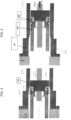
- Figs 3 and 4 show a locking system according to this disclosure, where the locking pin and actuator are configured such that the pin is decoupled from the actuator when in the locking position. In this way, loads on the pin are not transferred to the actuator.
- the locking system comprises a locking pin 400 that is configured, as in the conventional arrangement described above, to be driven through the passage defined by the holes in the intermeshing lugs of relatively pivotal parts.
- the intermeshing lugs are not shown in Figs. 3 and 4 as these are the same as described above. These are, therefore, represented by a simple aircraft structure 500 in these figures.
- the pin 400 is driven into and out of the lugs by means of an actuator 600.
- the actuator has an actuator body 601 which has an internal profile defining a first diameter section 602 and a second, wider diameter section 603.
- the actuator bore 606 along which the locking pin travels has a narrower section and a wider section.
- the locking pin 400 is caused to move along the bore 606 by means of a nut 700 that engages with an end 401 of the pin inside the actuator body.
- the nut 700 is driven by the actuator mechanism to cause movement of the locking pin 400 in the desired direction.
- the nut is preferably a threaded nut mounted onto a screw 900 to push the locking pin into position by travelling on the rotating screw 900.
- the nut is provided with radially expandible engagement features e.g. tines 800 that engage with the end 401 of the locking pin.
- the engagement tines are biased in the open position and will therefore return to the open or disengaged position when not pressed into engagement by an external force e.g. the force of the actuator bore wall.
- the locking pin may be provided with one or more grooves or recesses within which the tines can engage. Other means for providing engagement between the nut and the locking pin are also envisaged.
- the nut 700 is therefore driven in the direction of arrow A through the actuator bore along the narrower first section 602.
- the nut and the engagement tines are configured, and the bore is dimensioned, such that while the end of the pin and the nut are located in the narrower section of the bore, the inner walls of the actuator body defining the bore press the tines into engagement with the pin.
- the nut moves in direction A it pushes the locking pin into the locking position.
- the end 401 of the locking pin moves into the wider section 603 of the actuator bore, the pressing force of the actuator wall pushing the tines into engagement with the pin is removed and the tines are allowed to expand away from engagement with the pin as shown in Fig. 3 .
- the locking pin is therefore decoupled from the actuator. If the pin becomes loaded as shown in e.g. Fig. 2 , the loading is not transferred to the actuator.
- the nut 700 is drawn in the direction of arrow B which causes the engagement tines 800 to be pressed by the narrower diameter of the actuator inner wall and to re-engage with the locking pin.
- the tines 800 thus hook onto the end of the pin allowing the pin to be pulled by the nut back into the actuator body.
- This arrangement has the advantage that the pin, when in the locking position, is decoupled from the actuator, but can be re-attached to the actuator for movement to the unlocking position.
- the nut and locking pin are further withdrawn from the actuator bore allowing the tines to fully open and release the pin.
- the actuator design is relatively simple, small and light. Because the pin will be decoupled from the actuator in the locked position which is when the high loads can act on the pin, it is not necessary to design the actuator to withstand such loads. On the other hand, though, the locking pin can be easily removed for e.g. maintenance or exchange.
Landscapes
- Engineering & Computer Science (AREA)
- General Engineering & Computer Science (AREA)
- Mechanical Engineering (AREA)
- Aviation & Aerospace Engineering (AREA)
- Snaps, Bayonet Connections, Set Pins, And Snap Rings (AREA)
- Insertion Pins And Rivets (AREA)
- Lock And Its Accessories (AREA)
Claims (11)
- Verriegelungsstiftsystem, umfassend:einen Aktuator (600), der einen Aktuatorkörper (601) aufweist, der eine axiale Bohrung entlang seiner Länge definiert,einen Verriegelungsstift (400), der axial beweglich innerhalb der Bohrung (606) montiert ist, und Antriebsmittel (700, 900) zum Antreiben des Verriegelungsstifts axial entlang der Bohrung zwischen einer Verriegelungsposition, die sich von dem Aktuatorkörper erstreckt, und einer Entriegelungsposition, die relativ in den Aktuatorkörper eingezogen ist; dadurch gekennzeichnet, dass:die Antriebsmittel Eingriffsmittel (800) zum lösbaren Eingreifen in den Verriegelungsstift umfassen, wobei die Eingriffsmittel in eine offene Position vorgespannt sind, in der sie sich nicht in Eingriff mit dem Verriegelungsstift befinden, und wobeidie Bohrung einen ersten Abschnitt, der einen ersten Durchmesser aufweist, und einen zweiten Abschnitt, der einen zweiten größeren Durchmesser aufweist, umfasst, und wobei die Bohrung und die Eingriffsmittel so konfiguriert sind, dass, wenn sich die Eingriffsmittel in dem ersten Abschnitt befinden, der Aktuatorkörper die Eingriffsmittel in eine geschlossene Position zwingt, um mit dem Verriegelungsstift einzugreifen, und wenn sich die Eingriffsmittel in dem zweiten Abschnitt befinden, sie in die offene Position und außer Eingriff mit dem Verriegelungsstift zurückkehren.
- System nach Anspruch 1, so konfiguriert, dass, wenn sich das Antriebsmittel in eine Richtung bewegt, um den Verriegelungsstift von der Entriegelungsposition in die Verriegelungsposition zu bewegen, sich die Eingriffsmittel von dem ersten Abschnitt zu dem zweiten Abschnitt bewegen, sodass die Eingriffsmittel offen sind, wenn sich der Verriegelungsstift in der Verriegelungsposition befindet, und wenn sich das Antriebsmittel in einer gegenüberliegenden Richtung zu der Verriegelungsposition hin bewegt, sich die Eingriffsmittel von dem zweiten Abschnitt zu dem ersten Abschnitt bewegen, um den Verriegelungsstift (400) zu schließen und in ihn einzugreifen.
- System nach Anspruch 1 oder 2, wobei die Eingriffsmittel eine Vielzahl von elastischen Zinken (800) umfassen und wobei der Verriegelungsstift (400) eine umlaufende Nut aufweist, in die die Zinken in der geschlossenen Position eingreifen.
- System nach einem der vorhergehenden Ansprüche, wobei das Antriebsmittel eine Mutter (700) umfasst, die auf einer Schraube (900) montiert ist, die angeordnet ist, um sich entlang der Schraube in einer axialen Richtung zwischen der Verriegelungs- und der Entriegelungsrichtung zu bewegen.
- Faltbares System, umfassend zwei relativ faltbare Teile, die jeweils Scharnieransätze aufweisen, wobei die Scharnieransätze des einen Teils mit den Scharnieransätzen des anderen Teils ineinandergreifen, um ein Scharnier zu bilden, um die relative Schwenkbewegung zwischen den Teilen zu definieren, und ein Verriegelungsstiftsystem nach einem der vorhergehenden Ansprüche, wobei das Scharnier einen Verriegelungsstiftdurchgang dadurch definiert, um den Verriegelungsstift des Verriegelungsstiftsystems zu empfangen, um die Teile in Bezug aufeinander in einer gegebenen Schwenkbeziehung zu verriegeln.
- System nach Anspruch 5, wobei eines der Teile ein feststehendes Teil und das andere ein bewegliches Teil ist, das relativ zu dem feststehenden Teil faltbar ist.
- Faltbares System nach Anspruch 5 oder 6, wobei es sich um ein faltbares Flügelsystem handelt, wobei eines der Teile ein festes Flügelteil und das andere Teil eine faltbare Flügelspitze ist.
- System nach Anspruch 7, wobei es sich um ein faltbares Flügelsystem eines Luftfahrzeugs handelt.
- Verfahren zum Verriegeln und Entriegeln von zwei relativ faltbaren Teilen unter Verwendung des Verriegelungsstiftsystems nach einem der Ansprüche 1 bis 4, umfassend Antreiben des Verriegelungsstifts durch ein die zwei Teile verbindendes Scharnier, wodurch der Verriegelungsstift durch das Antriebsmittel, das in den Verriegelungsstift eingreift, um den Stift in die Verriegelungsposition zu treiben, in eine Verriegelungsposition getrieben wird, wobei das Verfahren ferner Lösen des Antriebsmittels von dem Verriegelungsstift umfasst, wenn sich der Verriegelungsstift in der Verriegelungsposition befindet.
- Verfahren nach Anspruch 9, ferner umfassend erneutes Ineingriffnehmen des Antriebsmittels mit dem Verriegelungsstift, um den Verriegelungsstift in eine Entriegelungsposition zurückzuziehen.
- Verfahren nach Anspruch 9, wodurch das Antriebsmittel bei dem Bewegen in die Verriegelungsposition durch eine erste Bohrung läuft, die eine Abmessung aufweist, die Eingriffsmittel des Antriebsmittels in Eingriff mit dem Verriegelungsstift und anschließend in eine zweite Bohrung mit größerem Durchmesser als die erste Bohrung drückt, sodass die Eingriffsmittel aus dem Eingriff mit dem Verriegelungsstift gelöst werden.
Priority Applications (4)
| Application Number | Priority Date | Filing Date | Title |
|---|---|---|---|
| EP21275086.3A EP4105516B1 (de) | 2021-06-18 | 2021-06-18 | Lastentkopplung für faltflügel |
| CA3159222A CA3159222A1 (en) | 2021-06-18 | 2022-05-11 | Load decouple for folding wing |
| US17/829,852 US12296949B2 (en) | 2021-06-18 | 2022-06-01 | Load decouple for folding wing |
| BR102022011921-0A BR102022011921A2 (pt) | 2021-06-18 | 2022-06-15 | Sistema de pino de travamento, sistema dobrável, e, método de travamento e destravamento de duas partes relativamente dobráveis |
Applications Claiming Priority (1)
| Application Number | Priority Date | Filing Date | Title |
|---|---|---|---|
| EP21275086.3A EP4105516B1 (de) | 2021-06-18 | 2021-06-18 | Lastentkopplung für faltflügel |
Publications (2)
| Publication Number | Publication Date |
|---|---|
| EP4105516A1 EP4105516A1 (de) | 2022-12-21 |
| EP4105516B1 true EP4105516B1 (de) | 2024-12-25 |
Family
ID=76553664
Family Applications (1)
| Application Number | Title | Priority Date | Filing Date |
|---|---|---|---|
| EP21275086.3A Active EP4105516B1 (de) | 2021-06-18 | 2021-06-18 | Lastentkopplung für faltflügel |
Country Status (4)
| Country | Link |
|---|---|
| US (1) | US12296949B2 (de) |
| EP (1) | EP4105516B1 (de) |
| BR (1) | BR102022011921A2 (de) |
| CA (1) | CA3159222A1 (de) |
Family Cites Families (20)
| Publication number | Priority date | Publication date | Assignee | Title |
|---|---|---|---|---|
| US4215587A (en) * | 1977-08-02 | 1980-08-05 | The Boeing Company | Folding mechanism |
| US4566150A (en) * | 1981-12-21 | 1986-01-28 | Little Giant Industries, Inc. | Ladder hinge and multi-position locking mechanism therefor |
| US4564974A (en) * | 1984-04-03 | 1986-01-21 | Mcgrail John F | Security hinge |
| US5426819A (en) * | 1991-11-25 | 1995-06-27 | Rohn; William B. | Door holding method and apparatus |
| US5310138A (en) * | 1991-12-30 | 1994-05-10 | Alliedsignal Inc. | Wing fold actuator system for aircraft |
| US5381986A (en) * | 1992-01-30 | 1995-01-17 | The Boeing Company | Folding wing-tip system |
| US5201479A (en) * | 1992-01-30 | 1993-04-13 | The Boeing Company | Self-monitoring latch pin lock for folding wing aircraft |
| US6032418A (en) * | 1998-11-09 | 2000-03-07 | Moog Inc. | Driven hinge with automatic driver-operated lock |
| US6591453B2 (en) * | 2001-09-14 | 2003-07-15 | John E. Jenks | Locking hinge system |
| WO2006007713A1 (en) * | 2004-07-20 | 2006-01-26 | Robin Lee Dickson | Linear actuator |
| JP5116147B2 (ja) * | 2007-11-13 | 2013-01-09 | パラマウントベッド株式会社 | 荷重センサ内蔵アクチュエータ |
| GB0813906D0 (en) * | 2008-07-30 | 2008-09-03 | Goodrich Actuation Systems Ltd | Actuator |
| US8844389B2 (en) * | 2011-12-14 | 2014-09-30 | Woodward Hrt, Inc. | Automatically locking linear actuator |
| US20140259532A1 (en) * | 2013-03-15 | 2014-09-18 | Matthew David Millard | Locking hinge and clamping device |
| GB201701850D0 (en) * | 2017-02-03 | 2017-03-22 | Airbus Operations Ltd | A Rotational joint for an aircraft folding wing |
| EP3360779B1 (de) * | 2017-02-09 | 2020-07-08 | The Boeing Company | System zum verriegeln und sperren eines klappflügels |
| US10808808B2 (en) * | 2017-05-05 | 2020-10-20 | Sierra Nevada Corporation | Expanding pin assembly controlled by actuator for locking and unlocking mechanical joint |
| FR3068421B1 (fr) * | 2017-06-29 | 2019-07-26 | Zodiac Actuation Systems | Dispositif de verrouillage pour actionneur electromecanique |
| US11370526B2 (en) * | 2018-05-31 | 2022-06-28 | Airbus Operations Gmbh | Latching device for a wing arrangement for an aircraft |
| CN113382929A (zh) | 2019-06-28 | 2021-09-10 | 空中客车德国运营有限责任公司 | 用于飞行器的机翼 |
-
2021
- 2021-06-18 EP EP21275086.3A patent/EP4105516B1/de active Active
-
2022
- 2022-05-11 CA CA3159222A patent/CA3159222A1/en active Pending
- 2022-06-01 US US17/829,852 patent/US12296949B2/en active Active
- 2022-06-15 BR BR102022011921-0A patent/BR102022011921A2/pt unknown
Also Published As
| Publication number | Publication date |
|---|---|
| CA3159222A1 (en) | 2022-12-18 |
| US20220402591A1 (en) | 2022-12-22 |
| US12296949B2 (en) | 2025-05-13 |
| BR102022011921A2 (pt) | 2022-12-27 |
| EP4105516A1 (de) | 2022-12-21 |
Similar Documents
| Publication | Publication Date | Title |
|---|---|---|
| EP2604514B1 (de) | Linearer Aktuator mit automatischer Sperre | |
| EP2527664B1 (de) | Staudruckluftturbineneinsatzbetätiger mit Verriegelungsmitteln | |
| US9038964B2 (en) | Control surface assembly | |
| US11319053B2 (en) | Secondary locking mechanism | |
| EP3929075B1 (de) | Fahrwerksschachtsystem und betriebsverfahren | |
| US10605199B2 (en) | Cylinder with integrated locking | |
| EP3254957B1 (de) | Verriegelungsvorrichtung für eine zusammenklappbare flügelanordnung | |
| EP3196126B1 (de) | Ver- und entriegelungsmechnismus | |
| EP4105516B1 (de) | Lastentkopplung für faltflügel | |
| US10837529B2 (en) | Electrical telescopic strut construction | |
| EP4261429A1 (de) | Bremse ohne rückwärtsgang für ein betätigungssystem und verfahren einer flugsteuerung | |
| US8590287B2 (en) | Device for opening and closing a thrust reverser door of a jet engine | |
| EP4725831A1 (de) | Betätigungssystem für klappbare flügelspitzen | |
| WO2006081664A1 (en) | Alternative uplock release assembly | |
| CA2610490C (en) | Alternative uplock release assembly | |
| US4058331A (en) | Remotely actuated two stage structural latch | |
| CN121799600A (zh) | 飞行器机翼、飞行器、铰接装置、齿轮式旋转致动器和接合环 | |
| CN119460058A (zh) | 一种机组应急跳伞舱门及其机构 |
Legal Events
| Date | Code | Title | Description |
|---|---|---|---|
| PUAI | Public reference made under article 153(3) epc to a published international application that has entered the european phase |
Free format text: ORIGINAL CODE: 0009012 |
|
| STAA | Information on the status of an ep patent application or granted ep patent |
Free format text: STATUS: THE APPLICATION HAS BEEN PUBLISHED |
|
| AK | Designated contracting states |
Kind code of ref document: A1 Designated state(s): AL AT BE BG CH CY CZ DE DK EE ES FI FR GB GR HR HU IE IS IT LI LT LU LV MC MK MT NL NO PL PT RO RS SE SI SK SM TR |
|
| STAA | Information on the status of an ep patent application or granted ep patent |
Free format text: STATUS: REQUEST FOR EXAMINATION WAS MADE |
|
| 17P | Request for examination filed |
Effective date: 20230620 |
|
| RBV | Designated contracting states (corrected) |
Designated state(s): AL AT BE BG CH CY CZ DE DK EE ES FI FR GB GR HR HU IE IS IT LI LT LU LV MC MK MT NL NO PL PT RO RS SE SI SK SM TR |
|
| REG | Reference to a national code |
Ref country code: DE Ref legal event code: R079 Free format text: PREVIOUS MAIN CLASS: F16H0025200000 Ipc: B64C0003560000 Ref document number: 602021023832 Country of ref document: DE |
|
| GRAP | Despatch of communication of intention to grant a patent |
Free format text: ORIGINAL CODE: EPIDOSNIGR1 |
|
| STAA | Information on the status of an ep patent application or granted ep patent |
Free format text: STATUS: GRANT OF PATENT IS INTENDED |
|
| RIC1 | Information provided on ipc code assigned before grant |
Ipc: F16H 25/20 20060101ALI20240710BHEP Ipc: F16H 25/24 20060101ALI20240710BHEP Ipc: B64C 3/56 20060101AFI20240710BHEP |
|
| INTG | Intention to grant announced |
Effective date: 20240809 |
|
| GRAS | Grant fee paid |
Free format text: ORIGINAL CODE: EPIDOSNIGR3 |
|
| GRAA | (expected) grant |
Free format text: ORIGINAL CODE: 0009210 |
|
| STAA | Information on the status of an ep patent application or granted ep patent |
Free format text: STATUS: THE PATENT HAS BEEN GRANTED |
|
| AK | Designated contracting states |
Kind code of ref document: B1 Designated state(s): AL AT BE BG CH CY CZ DE DK EE ES FI FR GB GR HR HU IE IS IT LI LT LU LV MC MK MT NL NO PL PT RO RS SE SI SK SM TR |
|
| REG | Reference to a national code |
Ref country code: GB Ref legal event code: FG4D |
|
| REG | Reference to a national code |
Ref country code: CH Ref legal event code: EP |
|
| REG | Reference to a national code |
Ref country code: DE Ref legal event code: R096 Ref document number: 602021023832 Country of ref document: DE |
|
| REG | Reference to a national code |
Ref country code: IE Ref legal event code: FG4D |
|
| REG | Reference to a national code |
Ref country code: LT Ref legal event code: MG9D |
|
| PG25 | Lapsed in a contracting state [announced via postgrant information from national office to epo] |
Ref country code: HR Free format text: LAPSE BECAUSE OF FAILURE TO SUBMIT A TRANSLATION OF THE DESCRIPTION OR TO PAY THE FEE WITHIN THE PRESCRIBED TIME-LIMIT Effective date: 20241225 |
|
| PG25 | Lapsed in a contracting state [announced via postgrant information from national office to epo] |
Ref country code: FI Free format text: LAPSE BECAUSE OF FAILURE TO SUBMIT A TRANSLATION OF THE DESCRIPTION OR TO PAY THE FEE WITHIN THE PRESCRIBED TIME-LIMIT Effective date: 20241225 |
|
| PG25 | Lapsed in a contracting state [announced via postgrant information from national office to epo] |
Ref country code: BG Free format text: LAPSE BECAUSE OF FAILURE TO SUBMIT A TRANSLATION OF THE DESCRIPTION OR TO PAY THE FEE WITHIN THE PRESCRIBED TIME-LIMIT Effective date: 20241225 |
|
| PG25 | Lapsed in a contracting state [announced via postgrant information from national office to epo] |
Ref country code: NO Free format text: LAPSE BECAUSE OF FAILURE TO SUBMIT A TRANSLATION OF THE DESCRIPTION OR TO PAY THE FEE WITHIN THE PRESCRIBED TIME-LIMIT Effective date: 20250325 |
|
| PG25 | Lapsed in a contracting state [announced via postgrant information from national office to epo] |
Ref country code: GR Free format text: LAPSE BECAUSE OF FAILURE TO SUBMIT A TRANSLATION OF THE DESCRIPTION OR TO PAY THE FEE WITHIN THE PRESCRIBED TIME-LIMIT Effective date: 20250326 Ref country code: LV Free format text: LAPSE BECAUSE OF FAILURE TO SUBMIT A TRANSLATION OF THE DESCRIPTION OR TO PAY THE FEE WITHIN THE PRESCRIBED TIME-LIMIT Effective date: 20241225 |
|
| PG25 | Lapsed in a contracting state [announced via postgrant information from national office to epo] |
Ref country code: RS Free format text: LAPSE BECAUSE OF FAILURE TO SUBMIT A TRANSLATION OF THE DESCRIPTION OR TO PAY THE FEE WITHIN THE PRESCRIBED TIME-LIMIT Effective date: 20250325 |
|
| REG | Reference to a national code |
Ref country code: NL Ref legal event code: MP Effective date: 20241225 |
|
| PG25 | Lapsed in a contracting state [announced via postgrant information from national office to epo] |
Ref country code: NL Free format text: LAPSE BECAUSE OF FAILURE TO SUBMIT A TRANSLATION OF THE DESCRIPTION OR TO PAY THE FEE WITHIN THE PRESCRIBED TIME-LIMIT Effective date: 20241225 |
|
| REG | Reference to a national code |
Ref country code: AT Ref legal event code: MK05 Ref document number: 1753970 Country of ref document: AT Kind code of ref document: T Effective date: 20241225 |
|
| PG25 | Lapsed in a contracting state [announced via postgrant information from national office to epo] |
Ref country code: SM Free format text: LAPSE BECAUSE OF FAILURE TO SUBMIT A TRANSLATION OF THE DESCRIPTION OR TO PAY THE FEE WITHIN THE PRESCRIBED TIME-LIMIT Effective date: 20241225 |
|
| PG25 | Lapsed in a contracting state [announced via postgrant information from national office to epo] |
Ref country code: PL Free format text: LAPSE BECAUSE OF FAILURE TO SUBMIT A TRANSLATION OF THE DESCRIPTION OR TO PAY THE FEE WITHIN THE PRESCRIBED TIME-LIMIT Effective date: 20241225 |
|
| PGFP | Annual fee paid to national office [announced via postgrant information from national office to epo] |
Ref country code: DE Payment date: 20250520 Year of fee payment: 5 |
|
| PG25 | Lapsed in a contracting state [announced via postgrant information from national office to epo] |
Ref country code: ES Free format text: LAPSE BECAUSE OF FAILURE TO SUBMIT A TRANSLATION OF THE DESCRIPTION OR TO PAY THE FEE WITHIN THE PRESCRIBED TIME-LIMIT Effective date: 20241225 |
|
| PGFP | Annual fee paid to national office [announced via postgrant information from national office to epo] |
Ref country code: GB Payment date: 20250520 Year of fee payment: 5 |
|
| PG25 | Lapsed in a contracting state [announced via postgrant information from national office to epo] |
Ref country code: IS Free format text: LAPSE BECAUSE OF FAILURE TO SUBMIT A TRANSLATION OF THE DESCRIPTION OR TO PAY THE FEE WITHIN THE PRESCRIBED TIME-LIMIT Effective date: 20250425 |
|
| PGFP | Annual fee paid to national office [announced via postgrant information from national office to epo] |
Ref country code: IT Payment date: 20250520 Year of fee payment: 5 |
|
| PG25 | Lapsed in a contracting state [announced via postgrant information from national office to epo] |
Ref country code: PT Free format text: LAPSE BECAUSE OF FAILURE TO SUBMIT A TRANSLATION OF THE DESCRIPTION OR TO PAY THE FEE WITHIN THE PRESCRIBED TIME-LIMIT Effective date: 20250428 |
|
| PG25 | Lapsed in a contracting state [announced via postgrant information from national office to epo] |
Ref country code: EE Free format text: LAPSE BECAUSE OF FAILURE TO SUBMIT A TRANSLATION OF THE DESCRIPTION OR TO PAY THE FEE WITHIN THE PRESCRIBED TIME-LIMIT Effective date: 20241225 |
|
| PGFP | Annual fee paid to national office [announced via postgrant information from national office to epo] |
Ref country code: FR Payment date: 20250520 Year of fee payment: 5 |
|
| PG25 | Lapsed in a contracting state [announced via postgrant information from national office to epo] |
Ref country code: RO Free format text: LAPSE BECAUSE OF FAILURE TO SUBMIT A TRANSLATION OF THE DESCRIPTION OR TO PAY THE FEE WITHIN THE PRESCRIBED TIME-LIMIT Effective date: 20241225 Ref country code: AT Free format text: LAPSE BECAUSE OF FAILURE TO SUBMIT A TRANSLATION OF THE DESCRIPTION OR TO PAY THE FEE WITHIN THE PRESCRIBED TIME-LIMIT Effective date: 20241225 |
|
| PG25 | Lapsed in a contracting state [announced via postgrant information from national office to epo] |
Ref country code: SK Free format text: LAPSE BECAUSE OF FAILURE TO SUBMIT A TRANSLATION OF THE DESCRIPTION OR TO PAY THE FEE WITHIN THE PRESCRIBED TIME-LIMIT Effective date: 20241225 |
|
| PG25 | Lapsed in a contracting state [announced via postgrant information from national office to epo] |
Ref country code: CZ Free format text: LAPSE BECAUSE OF FAILURE TO SUBMIT A TRANSLATION OF THE DESCRIPTION OR TO PAY THE FEE WITHIN THE PRESCRIBED TIME-LIMIT Effective date: 20241225 |
|
| PG25 | Lapsed in a contracting state [announced via postgrant information from national office to epo] |
Ref country code: SE Free format text: LAPSE BECAUSE OF FAILURE TO SUBMIT A TRANSLATION OF THE DESCRIPTION OR TO PAY THE FEE WITHIN THE PRESCRIBED TIME-LIMIT Effective date: 20241225 |
|
| REG | Reference to a national code |
Ref country code: DE Ref legal event code: R097 Ref document number: 602021023832 Country of ref document: DE |
|
| PG25 | Lapsed in a contracting state [announced via postgrant information from national office to epo] |
Ref country code: DK Free format text: LAPSE BECAUSE OF FAILURE TO SUBMIT A TRANSLATION OF THE DESCRIPTION OR TO PAY THE FEE WITHIN THE PRESCRIBED TIME-LIMIT Effective date: 20241225 |
|
| PLBE | No opposition filed within time limit |
Free format text: ORIGINAL CODE: 0009261 |
|
| STAA | Information on the status of an ep patent application or granted ep patent |
Free format text: STATUS: NO OPPOSITION FILED WITHIN TIME LIMIT |
|
| REG | Reference to a national code |
Ref country code: CH Ref legal event code: L10 Free format text: ST27 STATUS EVENT CODE: U-0-0-L10-L00 (AS PROVIDED BY THE NATIONAL OFFICE) Effective date: 20251105 |
|
| 26N | No opposition filed |
Effective date: 20250926 |
|
| REG | Reference to a national code |
Ref country code: CH Ref legal event code: H13 Free format text: ST27 STATUS EVENT CODE: U-0-0-H10-H13 (AS PROVIDED BY THE NATIONAL OFFICE) Effective date: 20260127 |
|
| PG25 | Lapsed in a contracting state [announced via postgrant information from national office to epo] |
Ref country code: MC Free format text: LAPSE BECAUSE OF FAILURE TO SUBMIT A TRANSLATION OF THE DESCRIPTION OR TO PAY THE FEE WITHIN THE PRESCRIBED TIME-LIMIT Effective date: 20241225 |
|
| PG25 | Lapsed in a contracting state [announced via postgrant information from national office to epo] |
Ref country code: LU Free format text: LAPSE BECAUSE OF NON-PAYMENT OF DUE FEES Effective date: 20250618 |
|
| REG | Reference to a national code |
Ref country code: BE Ref legal event code: MM Effective date: 20250630 |
|
| PG25 | Lapsed in a contracting state [announced via postgrant information from national office to epo] |
Ref country code: IE Free format text: LAPSE BECAUSE OF NON-PAYMENT OF DUE FEES Effective date: 20250618 |
|
| PG25 | Lapsed in a contracting state [announced via postgrant information from national office to epo] |
Ref country code: BE Free format text: LAPSE BECAUSE OF NON-PAYMENT OF DUE FEES Effective date: 20250630 |
|
| PG25 | Lapsed in a contracting state [announced via postgrant information from national office to epo] |
Ref country code: CH Free format text: LAPSE BECAUSE OF NON-PAYMENT OF DUE FEES Effective date: 20250630 |