EP4105593A1 - Unterschall, expansions- und bleifreies projektil - Google Patents
Unterschall, expansions- und bleifreies projektil Download PDFInfo
- Publication number
- EP4105593A1 EP4105593A1 EP22176267.7A EP22176267A EP4105593A1 EP 4105593 A1 EP4105593 A1 EP 4105593A1 EP 22176267 A EP22176267 A EP 22176267A EP 4105593 A1 EP4105593 A1 EP 4105593A1
- Authority
- EP
- European Patent Office
- Prior art keywords
- projectile
- expanding
- subsonic
- lead
- tip
- Prior art date
- Legal status (The legal status is an assumption and is not a legal conclusion. Google has not performed a legal analysis and makes no representation as to the accuracy of the status listed.)
- Withdrawn
Links
- 229910001369 Brass Inorganic materials 0.000 claims abstract description 13
- 239000010951 brass Substances 0.000 claims abstract description 13
- RYGMFSIKBFXOCR-UHFFFAOYSA-N Copper Chemical compound [Cu] RYGMFSIKBFXOCR-UHFFFAOYSA-N 0.000 claims abstract description 9
- 229910052802 copper Inorganic materials 0.000 claims abstract description 9
- 239000010949 copper Substances 0.000 claims abstract description 9
- 239000007787 solid Substances 0.000 claims abstract description 4
- 239000000463 material Substances 0.000 claims description 13
- 230000003247 decreasing effect Effects 0.000 claims description 6
- 230000007480 spreading Effects 0.000 description 15
- 210000004872 soft tissue Anatomy 0.000 description 8
- 230000000694 effects Effects 0.000 description 3
- 239000011521 glass Substances 0.000 description 3
- 239000002184 metal Substances 0.000 description 3
- 229910052751 metal Inorganic materials 0.000 description 3
- 230000006872 improvement Effects 0.000 description 2
- 235000001674 Agaricus brunnescens Nutrition 0.000 description 1
- 229910000881 Cu alloy Inorganic materials 0.000 description 1
- 230000004075 alteration Effects 0.000 description 1
- 230000001419 dependent effect Effects 0.000 description 1
- 239000005357 flat glass Substances 0.000 description 1
- 238000007654 immersion Methods 0.000 description 1
- 230000004048 modification Effects 0.000 description 1
- 238000012986 modification Methods 0.000 description 1
- 230000003252 repetitive effect Effects 0.000 description 1
- 239000011343 solid material Substances 0.000 description 1
- 230000003313 weakening effect Effects 0.000 description 1
Images


Classifications
-
- F—MECHANICAL ENGINEERING; LIGHTING; HEATING; WEAPONS; BLASTING
- F42—AMMUNITION; BLASTING
- F42B—EXPLOSIVE CHARGES, e.g. FOR BLASTING, FIREWORKS, AMMUNITION
- F42B12/00—Projectiles, missiles or mines characterised by the warhead, the intended effect, or the material
- F42B12/02—Projectiles, missiles or mines characterised by the warhead, the intended effect, or the material characterised by the warhead or the intended effect
- F42B12/34—Projectiles, missiles or mines characterised by the warhead, the intended effect, or the material characterised by the warhead or the intended effect expanding before or on impact, i.e. of dumdum or mushroom type
-
- F—MECHANICAL ENGINEERING; LIGHTING; HEATING; WEAPONS; BLASTING
- F42—AMMUNITION; BLASTING
- F42B—EXPLOSIVE CHARGES, e.g. FOR BLASTING, FIREWORKS, AMMUNITION
- F42B12/00—Projectiles, missiles or mines characterised by the warhead, the intended effect, or the material
- F42B12/72—Projectiles, missiles or mines characterised by the warhead, the intended effect, or the material characterised by the material
- F42B12/74—Projectiles, missiles or mines characterised by the warhead, the intended effect, or the material characterised by the material of the core or solid body
Definitions
- the present invention relates to subsonic projectiles.
- the present invention relates to a subsonic, expanding and lead-free projectile according to the preamble of claim 1.
- subsonic projectiles are known from prior art.
- subsonic projectiles are designed to operate in such velocities that the supersonic shockwave is avoided i.e. at velocities at least below the speed of sound, which is 343 m/s at 20 °C but depends on temperature such that in lower temperatures the velocity limit for the supersonic shockwave is lower.
- the subsonic projectiles have heavier bullet weights to retain as much energy as possible at the lower velocities.
- expanding projectiles are also known from prior art.
- expanding projectiles are designed to expand on impact and they are used as hunting bullets.
- EP2965038 is disclosed a bullet comprising a body made of solid-material metal and having on its nose and in the center axis thereof a cavity comprising at least two consecutive cavity parts. The diameter of the nose of the bullet is arranged to mushroom under the effect of a pressure directed to it as it hits its target.
- the diameter of each cavity part is smaller than the preceding one in such a manner that the consecutive cavity parts are formed in such a manner that in the direction away from the nose, the diameter of the next cavity part is clearly smaller than the diameter of the preceding cavity part, thus forming a step-shaped discontinuity area, and the consecutive cavity parts are of a length, in which the length of the cavity part on the nose side is clearly longer than the length of the next cavity part.
- the projectile body is also provided with predetermined breaking points designed as weakening in the wall thickness of the hollow opening.
- the wall thickness of the breaking point increases continuously from front to back.
- the projectile tip has a front part with projecting forward beyond the projectile body and has a larger cross-section than the hollow opening at the front.
- the projectile tip also has a rear part which is inserted into the hollow opening.
- An objective of the invention is to create a subsonic, expanding and lead-free projectile, in which the disadvantages and problems of the corresponding projectiles known from prior art are eliminated or at least minimized.
- Another objective of the invention is to create an improved subsonic, expanding and lead-free projectile, in which improved expandability is achieved.
- the projectile tip is shorter in axial direction than the depth of the hollow, cylindrical opening.
- the projectile tip is not supported onto the bottom of the hollow, cylindrical opening. This provides the possibility of the projectile to pass through a thin obstacle, for example a window glass, before expanding.
- a uniform ring is formed at the front part of the projectile body. This provides for slowing down spreading of the expanding parts of the projectile body during expanding of the projectile.
- the projectile body comprises axially extending slots, which slots extend a distance of 15-20 mm, advantageously about 18 mm, from the back edge of the ring in the front part of the projectile body.
- the slots begin to extend only after the uniform ring and do not provide a breaking point for the expanding parts of the projectile body but instead open the expanding parts of the projectile body during expanding of the projectile.
- the projectile tip has several different cross-sectional diameters, and its greatest diameter is located at the position, which is configured to be located just below the front part of the hollow opening of the projectile body such, that the outer surfaces of the projectile body and the projectile tip form a substantially uniform contour line.
- This provides further improvement in opening of the projectile tip, as thus, the projectile tip guides in contact the soft tissue material sideways and thus, spreads the expanding parts of the projectile body.
- the hollow, cylindrical opening has a stepwise from front part of the projectile towards the back part of the projectile decreasing diameter, which provides for beginning of the spreading of the projectile from the front part with low impact energy and for durability even if the projectile hits the target in sonic speed.
- the stepwise from front part of the projectile towards the back part of the projectile decreasing diameter is constructed with a smooth variation angle to minimize the notch effect as thus a fracturing point does not form to the expanding parts as the diameter changes.
- the depth of the hollow opening of the projectile body is 10 - 15 mm, most advantageously about 14,4 mm.
- the bottom of the hollow opening has a round-up, which decreased the notch effect and improves durability of the projectile.
- the weight of the projectile is 12,5 - 13,5 grams, most advantageously about 12,96 grams.
- the length of the projectile body without the projectile tip is 35 - 40 mm, most advantageously about 37,8 mm.
- the total length of the projectile body with the projectile tip mounted is 38 - 42 mm, most advantageously about 39,3 mm.
- the material of the projectile body is a solid body projectile body and made of lead-free metal, advantageously of copper, most advantageously extremely pure copper.
- the material of the projectile body has tensile strength (Rm) of 290-360 N/mm 2 and yield strength (0,2 % ) of at least 250 N/mm 2 .
- the material of the projectile body has hardness of HV 100-120.
- the material of the projectile tip is brass.
- the weight of the projectile tip is at least about 0,82 grams.
- the material of the projectile tip has hardness of about HV 150.
- the slots and the ring at the front of the projectile body are configured to significantly decrease the spreading resistance.
- the uniform ring holds the expanding part together during mounting of the projectile tip and controls spreading of the expanding parts such that the velocity of the projectile in soft tissue is configured to decrease to a level, in which no fracturing occurs in the expanding parts and thus, the projectile remains in one part. Additionally the uniform ring slows down spreading of the projectile, when it hits a hard obstacle, for example glass.
- the wedge shaped part of the projectile tip remaining inside the hollow opening of the projectile body guides the material of the soft tissue outwards and thus improves spreading of the expanding parts.
- the stages of operation of the projectile, when it hits a hard obstacle for example a glass window are:
- the weight of the projectile tip of brass increases the total weight of the projectile and transfers the center of mass of the projectile frontwards.
- figure 1 is schematically shown as a side view an advantageous example of projectile body of a subsonic, expanding and lead-free projectile according to the invention
- figure 2 is schematically shown as a partially cut view the advantageous example of the projectile body of the subsonic, expanding and lead-free projectile according to figure 1 ,
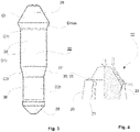
- FIG 3 is schematically shown a side view an advantageous example of a projectile tip of a subsonic, expanding and lead-free projectile according to the invention
- figure 4 is schematically shown as partial, partially cut view a front end of the advantageous example of the subsonic, expanding and lead-free projectile according to figures 1-3 before the projectile has first hit a hard obstacle and
- FIG. 5A - 5F is schematically shown an example of stages of operation of the projectile.
- the projectile 10 comprises a projectile body 20 and a projectile tip 30.
- the projectile body 20 is a solid body projectile body and made of lead-free metal, advantageously of copper, most advantageously extremely pure copper.
- the projectile tip 30 is made of brass material.
- the projectile body 20 comprises a cylindrical inner hollow opening 22, which is located at the imaginary center axis of the projectile body 20.
- the projectile body also is provided with slots 21, which are located radially spaced apart at the circumference of the inner hollow opening 22. Between the slots 21 expanding parts 25 of the projectile body 20 are located.
- the slots 21 extend to the outer surface of the projectile body 20 such, that they are open from the hollow opening 22 through the wall of the projectile body 20. In axial direction the slots 21 extend towards the bottom of the hollow opening 22 for a distance, which distance is shorter than the depth of the hollow opening 22.
- the projectile body 20 also comprises a uniform ring 23 formed at the front part of the projectile body 20.
- the hollow opening 22 has a stepwise from front part of the projectile towards the back part of the projectile decreasing diameter, D1, D2.
- the stepwise from front part of the projectile towards the back part of the projectile decreasing diameter D1, D2 is constructed with a smooth variation angle by conical parts C1, C2, C3.
- the bottom 24 of the hollow opening 22 has a rounding R24.
- the depth of the hollow opening 22 of the projectile body 20 is 10 - 15 mm, most advantageously about 14,4 mm.
- the projectile body 20 has thus at the circumferential area around the hollow opening 22 correspondingly altering wall thickness.
- the wall thickness increases from the tip to the opposite end of the projectile.
- the slots 21 the slots extend a distance of 15-20 mm, advantageously about 18 mm, from the back edge of the ring 23 located in the front part of the projectile body 20. Thus, the slots 21 begin to extend only after the uniform ring 23. The slots 21 limit the expanding parts 25 along the circumference of the projectile body 20.
- the projectile tip 30 comprises a tip end part 35, which is wedge-shaped, cylindrical mid parts 36 and tapered parts 37, 38 at the back end of the projectile tip 30.
- the projectile tip 30 is shorter in axial direction than the depth of the hollow opening 22 of the projectile body 20. Thus, the projectile tip 30 is not supported onto the bottom of the hollow opening, when mounted to its place before using the projectile 10.
- the projectile tip 30 has several different cross-sectional diameters Ct, C1t, D1t, C2t, D2t and its greatest diameter Dmax is located at the position, which is configured to be located just below the front part of the hollow opening 22 of the projectile body 20 such, that the outer surfaces of the projectile body 20 and the projectile tip 30 form a substantially uniform contour line. This provides further improvement in opening of the projectile tip, as thus, the projectile tip guides in contact the soft tissue material sideways and thus, spreads the expanding parts of the projectile body.
- the projectile tip 30 is inserted into the inner hollow opening 22 of the projectile body 20 such that the tip end part 35 of the projectile tip 30 remains outside the projectile body 20 and forms thus the outer tip of the projectile 10.
- the projectile tip 30 has the tapered tip end part 35.
- the weight of the projectile 10 is 12,5 - 13,5 grams, most advantageously about 12,96 grams.
- the length of the projectile body 20 without the projectile tip 30 is 35 - 40 mm, most advantageously about 37,8 mm and the total length of the projectile body 20 with the projectile tip 30 mounted before using is 38 - 42 mm, most advantageously about 39,3 mm.
- the slots 21 and the ring 23 at the front of the projectile body 20 are configured to significantly decrease the spreading resistance.
- the uniform ring 23 holds the expanding parts 25 together during mounting of the projectile tip 30 and controls spreading of the expanding parts 25 such that the velocity of the projectile 10 in soft tissue is configured to decrease to a level, in which no fracturing occurs in the expanding parts 25.
- the wedge shaped part 35 of the projectile tip 30 guides the material of the soft tissue outwards and thus improves spreading of the expanding parts 25, as shown by arrows in figure 4 .
- FIGS 5A - 5F is shown an example of the stages of the operation of the projectile.
- the projectile 10 from outside before it hits an obstacle.
- Corresponding stage is shown in figure 5B but as a partially cut view of the projectile 10.
- figure 5C is shown the stage, when the projectile 10 hits the obstacle and the hard projectile tip 30 of brass breaks the surface tension of the obstacle causing the projectile tip 30 to break the uniform ring 23 of the projectile body 20 and the wedge-shaped projectile tip 30 of brass to sink into the projectile body 20 due to the impact pressure.
- the hard projectile tip 30 of brass is below (behind) the lower edge of the ring 23.
Landscapes
- Engineering & Computer Science (AREA)
- Chemical & Material Sciences (AREA)
- Combustion & Propulsion (AREA)
- General Engineering & Computer Science (AREA)
- Physics & Mathematics (AREA)
- Thermal Sciences (AREA)
- Aiming, Guidance, Guns With A Light Source, Armor, Camouflage, And Targets (AREA)
- Powder Metallurgy (AREA)
- Percussive Tools And Related Accessories (AREA)
Applications Claiming Priority (1)
| Application Number | Priority Date | Filing Date | Title |
|---|---|---|---|
| FI20215692A FI129688B (en) | 2021-06-14 | 2021-06-14 | Subsonic, expanding and lead-free projectile |
Publications (1)
| Publication Number | Publication Date |
|---|---|
| EP4105593A1 true EP4105593A1 (de) | 2022-12-21 |
Family
ID=81854443
Family Applications (1)
| Application Number | Title | Priority Date | Filing Date |
|---|---|---|---|
| EP22176267.7A Withdrawn EP4105593A1 (de) | 2021-06-14 | 2022-05-31 | Unterschall, expansions- und bleifreies projektil |
Country Status (2)
| Country | Link |
|---|---|
| EP (1) | EP4105593A1 (de) |
| FI (1) | FI129688B (de) |
Citations (6)
| Publication number | Priority date | Publication date | Assignee | Title |
|---|---|---|---|---|
| DE2028238A1 (de) * | 1970-06-09 | 1971-12-16 | Umbach, Heinz, Dipl.-Ing., 4300 Essen | Jagdbüchsengeschoß mit Schlitzmantel |
| US4776279A (en) * | 1987-09-17 | 1988-10-11 | Pejsa Arthur J | Expanding ballistic projectile |
| US20150354930A1 (en) * | 2014-06-06 | 2015-12-10 | Lehigh Defense, LLC | Expanding subsonic projectile and cartridge utilizing same |
| EP2965038A1 (de) | 2013-03-08 | 2016-01-13 | Nurminen, Vesa | Geschoss und verfahren zum aufpilzen eines geschosses |
| DE102014224715A1 (de) | 2014-10-29 | 2016-05-04 | Metallwerk Elisenhütte GmbH | Unterschallpatrone mit einem Geschoss sowie Geschoss für eine solche |
| US20160216090A1 (en) * | 2013-12-31 | 2016-07-28 | Lehigh Defense, LLC | Expanding subsonic projectile and cartridge utilizing same |
-
2021
- 2021-06-14 FI FI20215692A patent/FI129688B/en active IP Right Grant
-
2022
- 2022-05-31 EP EP22176267.7A patent/EP4105593A1/de not_active Withdrawn
Patent Citations (6)
| Publication number | Priority date | Publication date | Assignee | Title |
|---|---|---|---|---|
| DE2028238A1 (de) * | 1970-06-09 | 1971-12-16 | Umbach, Heinz, Dipl.-Ing., 4300 Essen | Jagdbüchsengeschoß mit Schlitzmantel |
| US4776279A (en) * | 1987-09-17 | 1988-10-11 | Pejsa Arthur J | Expanding ballistic projectile |
| EP2965038A1 (de) | 2013-03-08 | 2016-01-13 | Nurminen, Vesa | Geschoss und verfahren zum aufpilzen eines geschosses |
| US20160216090A1 (en) * | 2013-12-31 | 2016-07-28 | Lehigh Defense, LLC | Expanding subsonic projectile and cartridge utilizing same |
| US20150354930A1 (en) * | 2014-06-06 | 2015-12-10 | Lehigh Defense, LLC | Expanding subsonic projectile and cartridge utilizing same |
| DE102014224715A1 (de) | 2014-10-29 | 2016-05-04 | Metallwerk Elisenhütte GmbH | Unterschallpatrone mit einem Geschoss sowie Geschoss für eine solche |
Also Published As
| Publication number | Publication date |
|---|---|
| FI20215692A1 (en) | 2022-06-30 |
| FI129688B (en) | 2022-06-30 |
Similar Documents
| Publication | Publication Date | Title |
|---|---|---|
| US10352669B2 (en) | Advanced aerodynamic projectile and method of making same | |
| US20220373309A1 (en) | Rifle cartridge with improved bullet upset and separation | |
| US6971315B2 (en) | Reduced-contaminant deformable bullet, preferably for small arms | |
| RU2125705C1 (ru) | Пуля с управляемым расширением (варианты) | |
| US7299750B2 (en) | Partial fragmentation and deformation bullets having an identical point of impact | |
| US3446147A (en) | Casing for the sabot of a projectile | |
| US9003974B2 (en) | Hollow-channel projectile nose and shaping of a projectile body in the nose region | |
| US6035501A (en) | Method of making a subcaliber kinetic energy projectile | |
| RU2597431C2 (ru) | Пуля боеприпаса стрелкового оружия | |
| US3905299A (en) | Discarding sabot projectiles | |
| RU2347177C2 (ru) | Бронебойный оперенный подкалиберный снаряд | |
| US20160047638A1 (en) | Material based impact reactive projectiles | |
| US12085370B2 (en) | Bullet | |
| US20240200918A1 (en) | Tool and method for producing a projectile and projectile | |
| ZA200602838B (en) | Hunting bullet with reduced aerodynamic resistance | |
| EP4105593A1 (de) | Unterschall, expansions- und bleifreies projektil | |
| US10969209B2 (en) | Segmenting pistol bullet | |
| US11639844B2 (en) | Penetrating and explosive projectile with stabilizing fin assembly | |
| US3948180A (en) | Non-explosive shaped-charge follow-through projectile | |
| US11703310B2 (en) | Penetrator, use of a penetrator, and projectile | |
| US3847082A (en) | Spin stabilized, discarding sabot projectile | |
| EP0275685A2 (de) | Lösbarer Treibkäfig | |
| CA3172762A1 (en) | Penetrator and use of a penetrator |
Legal Events
| Date | Code | Title | Description |
|---|---|---|---|
| PUAI | Public reference made under article 153(3) epc to a published international application that has entered the european phase |
Free format text: ORIGINAL CODE: 0009012 |
|
| STAA | Information on the status of an ep patent application or granted ep patent |
Free format text: STATUS: THE APPLICATION HAS BEEN PUBLISHED |
|
| AK | Designated contracting states |
Kind code of ref document: A1 Designated state(s): AL AT BE BG CH CY CZ DE DK EE ES FI FR GB GR HR HU IE IS IT LI LT LU LV MC MK MT NL NO PL PT RO RS SE SI SK SM TR |
|
| STAA | Information on the status of an ep patent application or granted ep patent |
Free format text: STATUS: THE APPLICATION IS DEEMED TO BE WITHDRAWN |
|
| 18D | Application deemed to be withdrawn |
Effective date: 20230622 |