EP4106095A1 - Batteriemodul - Google Patents
Batteriemodul Download PDFInfo
- Publication number
- EP4106095A1 EP4106095A1 EP20918974.5A EP20918974A EP4106095A1 EP 4106095 A1 EP4106095 A1 EP 4106095A1 EP 20918974 A EP20918974 A EP 20918974A EP 4106095 A1 EP4106095 A1 EP 4106095A1
- Authority
- EP
- European Patent Office
- Prior art keywords
- bus bar
- cell stack
- biasing
- bar plate
- cells
- Prior art date
- Legal status (The legal status is an assumption and is not a legal conclusion. Google has not performed a legal analysis and makes no representation as to the accuracy of the status listed.)
- Pending
Links
- 238000006073 displacement reaction Methods 0.000 claims abstract description 13
- 238000003825 pressing Methods 0.000 abstract description 10
- 230000001105 regulatory effect Effects 0.000 abstract description 4
- 238000007789 sealing Methods 0.000 description 12
- 238000006243 chemical reaction Methods 0.000 description 7
- 239000011347 resin Substances 0.000 description 6
- 229920005989 resin Polymers 0.000 description 6
- XEEYBQQBJWHFJM-UHFFFAOYSA-N Iron Chemical compound [Fe] XEEYBQQBJWHFJM-UHFFFAOYSA-N 0.000 description 4
- 239000004743 Polypropylene Substances 0.000 description 4
- 238000000034 method Methods 0.000 description 4
- 229920001707 polybutylene terephthalate Polymers 0.000 description 4
- -1 polypropylene Polymers 0.000 description 4
- 229920001155 polypropylene Polymers 0.000 description 4
- 230000005489 elastic deformation Effects 0.000 description 3
- 229910052751 metal Inorganic materials 0.000 description 3
- 239000002184 metal Substances 0.000 description 3
- 238000003466 welding Methods 0.000 description 3
- 239000004727 Noryl Substances 0.000 description 2
- 229920001207 Noryl Polymers 0.000 description 2
- 239000004721 Polyphenylene oxide Substances 0.000 description 2
- 229910052782 aluminium Inorganic materials 0.000 description 2
- XAGFODPZIPBFFR-UHFFFAOYSA-N aluminium Chemical compound [Al] XAGFODPZIPBFFR-UHFFFAOYSA-N 0.000 description 2
- 238000005452 bending Methods 0.000 description 2
- 230000000694 effects Effects 0.000 description 2
- 229910052742 iron Inorganic materials 0.000 description 2
- 230000013011 mating Effects 0.000 description 2
- 239000004417 polycarbonate Substances 0.000 description 2
- 229920000515 polycarbonate Polymers 0.000 description 2
- 229910001220 stainless steel Inorganic materials 0.000 description 2
- 239000010935 stainless steel Substances 0.000 description 2
- RYGMFSIKBFXOCR-UHFFFAOYSA-N Copper Chemical compound [Cu] RYGMFSIKBFXOCR-UHFFFAOYSA-N 0.000 description 1
- 244000268528 Platanus occidentalis Species 0.000 description 1
- 238000007792 addition Methods 0.000 description 1
- OJIJEKBXJYRIBZ-UHFFFAOYSA-N cadmium nickel Chemical compound [Ni].[Cd] OJIJEKBXJYRIBZ-UHFFFAOYSA-N 0.000 description 1
- 238000009833 condensation Methods 0.000 description 1
- 230000005494 condensation Effects 0.000 description 1
- 239000004020 conductor Substances 0.000 description 1
- 229910052802 copper Inorganic materials 0.000 description 1
- 239000010949 copper Substances 0.000 description 1
- 238000012217 deletion Methods 0.000 description 1
- 230000037430 deletion Effects 0.000 description 1
- 239000000428 dust Substances 0.000 description 1
- 239000003792 electrolyte Substances 0.000 description 1
- 230000002708 enhancing effect Effects 0.000 description 1
- 230000014509 gene expression Effects 0.000 description 1
- 229910001416 lithium ion Inorganic materials 0.000 description 1
- 229910052987 metal hydride Inorganic materials 0.000 description 1
- 125000006850 spacer group Chemical group 0.000 description 1
- XLYOFNOQVPJJNP-UHFFFAOYSA-N water Substances O XLYOFNOQVPJJNP-UHFFFAOYSA-N 0.000 description 1
Images



Classifications
-
- H—ELECTRICITY
- H01—ELECTRIC ELEMENTS
- H01M—PROCESSES OR MEANS, e.g. BATTERIES, FOR THE DIRECT CONVERSION OF CHEMICAL ENERGY INTO ELECTRICAL ENERGY
- H01M50/00—Constructional details or processes of manufacture of the non-active parts of electrochemical cells other than fuel cells, e.g. hybrid cells
- H01M50/50—Current conducting connections for cells or batteries
- H01M50/572—Means for preventing undesired use or discharge
-
- H—ELECTRICITY
- H01—ELECTRIC ELEMENTS
- H01M—PROCESSES OR MEANS, e.g. BATTERIES, FOR THE DIRECT CONVERSION OF CHEMICAL ENERGY INTO ELECTRICAL ENERGY
- H01M50/00—Constructional details or processes of manufacture of the non-active parts of electrochemical cells other than fuel cells, e.g. hybrid cells
- H01M50/20—Mountings; Secondary casings or frames; Racks, modules or packs; Suspension devices; Shock absorbers; Transport or carrying devices; Holders
- H01M50/204—Racks, modules or packs for multiple batteries or multiple cells
-
- H—ELECTRICITY
- H01—ELECTRIC ELEMENTS
- H01M—PROCESSES OR MEANS, e.g. BATTERIES, FOR THE DIRECT CONVERSION OF CHEMICAL ENERGY INTO ELECTRICAL ENERGY
- H01M50/00—Constructional details or processes of manufacture of the non-active parts of electrochemical cells other than fuel cells, e.g. hybrid cells
- H01M50/20—Mountings; Secondary casings or frames; Racks, modules or packs; Suspension devices; Shock absorbers; Transport or carrying devices; Holders
- H01M50/262—Mountings; Secondary casings or frames; Racks, modules or packs; Suspension devices; Shock absorbers; Transport or carrying devices; Holders with fastening means, e.g. locks
- H01M50/264—Mountings; Secondary casings or frames; Racks, modules or packs; Suspension devices; Shock absorbers; Transport or carrying devices; Holders with fastening means, e.g. locks for cells or batteries, e.g. straps, tie rods or peripheral frames
-
- H—ELECTRICITY
- H01—ELECTRIC ELEMENTS
- H01M—PROCESSES OR MEANS, e.g. BATTERIES, FOR THE DIRECT CONVERSION OF CHEMICAL ENERGY INTO ELECTRICAL ENERGY
- H01M50/00—Constructional details or processes of manufacture of the non-active parts of electrochemical cells other than fuel cells, e.g. hybrid cells
- H01M50/20—Mountings; Secondary casings or frames; Racks, modules or packs; Suspension devices; Shock absorbers; Transport or carrying devices; Holders
- H01M50/289—Mountings; Secondary casings or frames; Racks, modules or packs; Suspension devices; Shock absorbers; Transport or carrying devices; Holders characterised by spacing elements or positioning means within frames, racks or packs
- H01M50/291—Mountings; Secondary casings or frames; Racks, modules or packs; Suspension devices; Shock absorbers; Transport or carrying devices; Holders characterised by spacing elements or positioning means within frames, racks or packs characterised by their shape
-
- H—ELECTRICITY
- H01—ELECTRIC ELEMENTS
- H01M—PROCESSES OR MEANS, e.g. BATTERIES, FOR THE DIRECT CONVERSION OF CHEMICAL ENERGY INTO ELECTRICAL ENERGY
- H01M50/00—Constructional details or processes of manufacture of the non-active parts of electrochemical cells other than fuel cells, e.g. hybrid cells
- H01M50/50—Current conducting connections for cells or batteries
- H01M50/502—Interconnectors for connecting terminals of adjacent batteries; Interconnectors for connecting cells outside a battery casing
- H01M50/505—Interconnectors for connecting terminals of adjacent batteries; Interconnectors for connecting cells outside a battery casing comprising a single busbar
-
- H—ELECTRICITY
- H01—ELECTRIC ELEMENTS
- H01M—PROCESSES OR MEANS, e.g. BATTERIES, FOR THE DIRECT CONVERSION OF CHEMICAL ENERGY INTO ELECTRICAL ENERGY
- H01M50/00—Constructional details or processes of manufacture of the non-active parts of electrochemical cells other than fuel cells, e.g. hybrid cells
- H01M50/50—Current conducting connections for cells or batteries
- H01M50/502—Interconnectors for connecting terminals of adjacent batteries; Interconnectors for connecting cells outside a battery casing
- H01M50/507—Interconnectors for connecting terminals of adjacent batteries; Interconnectors for connecting cells outside a battery casing comprising an arrangement of two or more busbars within a container structure, e.g. busbar modules
-
- H—ELECTRICITY
- H01—ELECTRIC ELEMENTS
- H01M—PROCESSES OR MEANS, e.g. BATTERIES, FOR THE DIRECT CONVERSION OF CHEMICAL ENERGY INTO ELECTRICAL ENERGY
- H01M50/00—Constructional details or processes of manufacture of the non-active parts of electrochemical cells other than fuel cells, e.g. hybrid cells
- H01M50/50—Current conducting connections for cells or batteries
- H01M50/572—Means for preventing undesired use or discharge
- H01M50/584—Means for preventing undesired use or discharge for preventing incorrect connections inside or outside the batteries
- H01M50/588—Means for preventing undesired use or discharge for preventing incorrect connections inside or outside the batteries outside the batteries, e.g. incorrect connections of terminals or busbars
-
- H—ELECTRICITY
- H01—ELECTRIC ELEMENTS
- H01M—PROCESSES OR MEANS, e.g. BATTERIES, FOR THE DIRECT CONVERSION OF CHEMICAL ENERGY INTO ELECTRICAL ENERGY
- H01M50/00—Constructional details or processes of manufacture of the non-active parts of electrochemical cells other than fuel cells, e.g. hybrid cells
- H01M50/50—Current conducting connections for cells or batteries
- H01M50/572—Means for preventing undesired use or discharge
- H01M50/584—Means for preventing undesired use or discharge for preventing incorrect connections inside or outside the batteries
- H01M50/59—Means for preventing undesired use or discharge for preventing incorrect connections inside or outside the batteries characterised by the protection means
- H01M50/591—Covers
-
- Y—GENERAL TAGGING OF NEW TECHNOLOGICAL DEVELOPMENTS; GENERAL TAGGING OF CROSS-SECTIONAL TECHNOLOGIES SPANNING OVER SEVERAL SECTIONS OF THE IPC; TECHNICAL SUBJECTS COVERED BY FORMER USPC CROSS-REFERENCE ART COLLECTIONS [XRACs] AND DIGESTS
- Y02—TECHNOLOGIES OR APPLICATIONS FOR MITIGATION OR ADAPTATION AGAINST CLIMATE CHANGE
- Y02E—REDUCTION OF GREENHOUSE GAS [GHG] EMISSIONS, RELATED TO ENERGY GENERATION, TRANSMISSION OR DISTRIBUTION
- Y02E60/00—Enabling technologies; Technologies with a potential or indirect contribution to GHG emissions mitigation
- Y02E60/10—Energy storage using batteries
Definitions
- the present invention relates to a battery module.
- PTL 1 discloses a power storage module including: a cell stack in which a plurality of cells are stacked; a bus bar that electrically connects output terminals of the respective cells to each other; and a surface plate (bus bar plate) that covers a surface of the cell stack on which the output terminal is disposed. This surface plate has an opening at a position opposing the output terminal, and the bus bar is held by being fitted into the opening.
- a positioning pin is provided in one of a cell stack and a bus bar plate, and a positioning hole is provided in the other, and the cell stack and the bus bar plate are positioned by the positioning pin being passed through the positioning hole.
- positional deviation between the cell stack and the bus bar plate due to dimensions of each part and tolerance of positions easily occurs, and it is difficult to meet a demand for further enhancing positional accuracy of the cell stack and the bus bar plate.
- the present disclosure has been made in view of such situation, and an object of the present disclosure is to provide a technique for improving positioning accuracy between a cell stack and a bus bar plate.
- An aspect of the present disclosure is a battery module.
- This battery module includes: a cell stack in which a plurality of cells each having an output terminal are arrayed; a bus bar that electrically connects the output terminals of the plurality of cells to each other; and a bus bar plate that covers a surface of the cell stack on which the output terminal is disposed, that has an opening at a position overlapping with respective output terminals, the bus bar plate in which the bus bar is disposed in the opening.
- one of the bus bar plate and the cell stack is a first member and the other is a second member
- the first member has a biasing part
- the second member has a biasing receiver
- the first member and the second member are biased in opposite directions to each other by the biasing part pressing the second member, and displacement of the first member and the second member is regulated by the biasing receiver abutting on the first member.
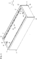
- Fig. 1 is a perspective view of a battery module according to a first exemplary embodiment.
- Fig. 1 is a perspective view of the battery module according to the first exemplary embodiment.
- Fig. 2 is an exploded perspective view of the battery module.
- Battery module 1 includes cell stack 2, a plurality of bus bars 4, and bus bar plate 6.
- Cell stack 2 has a structure in which a plurality of cells 8 are arrayed.
- Cell stack 2 includes the plurality of cells 8, a plurality of separators 10, and a pair of binding members 12.
- Each cell 8 is a rechargeable secondary cell such as a lithium-ion cell, a nickel-metal-hydride cell, or a nickel-cadmium cell.
- Each cell 8 is a so-called prismatic cell, and includes outer covering can 14 having a flat rectangular-parallelepiped shape.
- One surface of outer covering can 14 is provided with an opening having a substantially rectangular shape not illustrated, and an electrode body, an electrolyte, and the like are accommodated in outer covering can 14 through the opening.
- a substantially rectangular sealing plate 16 for closing the opening is fitted into the opening of outer covering can 14.
- a pair of output terminals 18 are disposed on sealing plate 16. Specifically, positive-electrode terminal 18a is disposed near one end in the long direction, and negative-electrode terminal 18b is disposed near the other end.
- positive-electrode terminal 18a and negative-electrode terminal 18b are collectively referred to as output terminal 18.
- Outer covering can 14, sealing plate 16, and output terminal 18 are conductors, and are made of metal such as aluminum, iron, or stainless steel, for example. Outer covering can 14 and sealing plate 16 are joined to each other by, for example, laser welding. Each output terminal 18 is inserted into a through-hole formed in sealing plate 16. An insulating seal member is interposed between respective output terminals 18 and respective through-holes. Outer covering can 14 may be covered with an insulating film not illustrated such as a shrink tube.
- Valve 19 is disposed between the pair of output terminals 18 in sealing plate 16.
- Valve 19 is configured to be opened when the internal pressure of cell 8 rises to equal to or greater than a predetermined value to release the gas inside cell 8.
- valve 19 includes a thin part having a thickness smaller than a thickness of another part provided in a part of sealing plate 16, and a linear groove formed on the surface of this thin part. In this configuration, when the internal pressure of cell 8 rises, the thin part tears from the groove as a starting point, so that valve 19 opens.
- sealing plate 16 is an upper surface of cell 8, and a bottom surface of outer covering can 14 opposing sealing plate 16 is a lower surface of cell 8.
- Cell 8 has four side surfaces connecting the upper surface and the lower surface. Two of the four side surfaces are a pair of long side surfaces connected to two opposing long sides of sealing plate 16. Each long side surface is a surface having the largest area among surfaces of cell 8, that is, a main surface. The remaining two side surfaces excluding the two long side surfaces are a pair of short side surfaces connected to the short side of sealing plate 16.
- a surface on an upper surface side of cell 8 is defined as an upper surface of cell stack 2
- a surface on a lower surface side of cell 8 is defined as a lower surface of cell stack 2
- a surface on a short side surface side of cell 8 is defined as a side surface of cell stack 2.
- the plurality of cells 8 are arrayed at predetermined intervals such that main surfaces of adjacent cells 8 oppose each other.
- cells 8 are arrayed in the horizontal direction.
- a direction in which cells 8 are arrayed is appropriately defined as array direction X
- a direction that is horizontal and orthogonal to array direction X is defined as horizontal direction Y
- a direction orthogonal to array direction X and horizontal direction Y is defined as vertical direction Z.
- Each cell 8 is disposed such that output terminal 18 faces the same direction.
- Each cell 8 of the present exemplary embodiment is disposed such that output terminal 18 faces upward in the vertical direction.
- cells 8 are arrayed such that positive-electrode terminal 18a of one cell 8 and negative-electrode terminal 18b of other cell 8 are adjacent to each other.
- positive-electrode terminal 18a of one cell 8 and positive-electrode terminal 18a of other cell 8 are arrayed adjacent to each other.
- Separator 10 is disposed between two adjacent cells 8. Accordingly, two cells 8 are electrically insulated from each other. Separator 10 is also called an insulating spacer, and is made of, for example, an insulating resin sheet. Examples of the resin constituting separator 10 include resins such as polypropylene (PP), polybutylene terephthalate (PBT), polycarbonate (PC), and Noryl (registered trademark) resin (modified PPE). Fig. 2 only illustrates some separators 10.
- PP polypropylene
- PBT polybutylene terephthalate
- PC polycarbonate
- Noryl resin modified PPE
- Binding member 12 is also called a bind bar, and is a long member that is long in array direction X of cells 8.
- the pair of binding members 12 are arrayed in horizontal direction Y.
- Each binding member 12 is made of metal such as iron or stainless steel, for example.
- the plurality of cells 8 are held between a pair of end plates not illustrated in array direction X in a state of being alternately arrayed with the plurality of separators 10.
- the pair of end plates are adjacent across separator 10 to cells 8 positioned at both ends in stacking direction X.
- the pair of binding members 12 are arranged so as to hold the plurality of cells 8, the plurality of separators 10, and the pair of end plates in horizontal direction Y, and both ends of each binding member 12 are fixed to the pair of end plates.
- binding member 12 has, at both ends in array direction X, a bent part overlapping the main surface of the end plate, and this bent part is fixed to the end plate by screwing or the like.
- the plurality of cells 8 are bound in array direction X by the pair of binding members 12 and positioned in array direction X.
- Each binding member 12 has a pair of arms 20 opposing each other in vertical direction Z.
- the plurality of cells 8 are held in vertical direction Z by the pair of arms 20.
- each cell 8 is positioned in vertical direction Z.
- Bus bar 4 is a substantially belt-shaped member made of metal such as copper or aluminum. One end of bus bar 4 is connected to positive-electrode terminal 18a of one cell 8 of two adjacent cells 8, and the other end is connected to negative-electrode terminal 18b of other cell 8. Consequently, output terminals 18 of cells 8 are electrically connected to each other. In bus bar 4, output terminals 18 having the same polarity in the plurality of adjacent cells 8 may be connected in parallel to form a cell block, and the cell blocks may be connected in series.
- Bus bar plate 6 is a plate-shaped member that covers an upper surface of cell stack 2 on which output terminal 18 is disposed. Bus bar plate 6 can also function as a part of a holder case that accommodates cell stack 2. Bus bar plate 6 is made of resin such as polypropylene (PP), polybutylene terephthalate (PBT), polycarbonate (PC), and Noryl (registered trademark) resin (modified PPE).
- PP polypropylene
- PBT polybutylene terephthalate
- PC polycarbonate
- Noryl resin modified PPE
- Bus bar plate 6 has a plurality of openings 22 through which respective output terminals 18 are exposed at positions overlapping respective output terminals 18 of the plurality of cells 8 in vertical direction Z.
- Bus bar 4 is disposed in each opening 22.
- bus bar plate 6 is placed on an upper surface of cell stack 2, and then bus bar 4 is fitted into each opening 22.
- bus bar 4 is fitted into each opening 22 of bus bar plate 6, and bus bar plate 6 in a state of holding the plurality of bus bars 4 is placed on the upper surface of cell stack 2.
- the plurality of bus bars 4 are positioned with respect to cell stack 2 by bus bar plate 6.
- Bus bar plate 6 is fixed to, for example, the end plate by screwing or the like in a state of being positioned with respect to cell stack 2.
- a cover plate not illustrated is placed on an upper surface of bus bar plate 6. By covering the upper surface of bus bar plate 6 with the cover plate, it is possible to suppress contact of dew condensation water, dust, or the like with output terminal 18, bus bar 4, or the like.
- bus bar plate 6 When one of bus bar plate 6 and cell stack 2 is a first member and the other is a second member, the first member has biasing part 26, and the second member has biasing receiver 28.
- bus bar plate 6 is the first member
- cell stack 2 is the second member.
- bus bar plate 6 may be the second member
- cell stack 2 may be the first member. That is, bus bar plate 6 may be provided with biasing receiver 28, and cell stack 2 may be provided with biasing part 26.
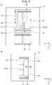
- Fig. 3(A) is an enlarged plan view illustrating a region including biasing part 26 in battery module 1.
- Fig. 3(B) is an enlarged plan view illustrating a region including biasing receiver 28 in battery module 1.
- Biasing part 26 has an elastically deformable shape, and presses cell stack 2 as the second member by its elastic force in a state where bus bar plate 6 is placed on cell stack 2.
- biasing part 26 presses separator 10. Therefore, separator 10 is mating member 24 that is a direct biasing target of bus bar plate 6.
- bus bar plate 6 as the first member and cell stack 2 as the second member are biased in opposite directions to each other.
- first direction A and second direction B are parallel to horizontal direction Y.
- biasing receiver 28 In a state where bus bar plate 6 and cell stack 2 are biased in opposite directions, biasing receiver 28 abuts on bus bar plate 6. This regulates displacement of bus bar plate 6 and cell stack 2.
- the elastic deformation amount of biasing part 26 and the positional relationship between biasing part 26 and biasing receiver 28 in horizontal direction Y are determined such that the first member abuts on biasing receiver 28 in a state where biasing force (pressing force) of biasing part 26 is applied to the second member.
- Bus bar plate 6 of the present exemplary embodiment has three openings 30 at the center in horizontal direction Y.
- Each opening 30 has a rectangular shape and has a pair of edges extending in array direction X and a pair of edges extending in horizontal direction Y.
- Two openings 30 are arranged at both ends in array direction X.
- Biasing part 26 is disposed in two openings 30.
- Biasing part 26 has a leaf spring shape as an example. More specifically, biasing part 26 includes: arm 32 that extends along the upper surface of cell stack 2 from an edge that extends in horizontal direction Y of opening 30 toward the center in array direction X; and tip end 34 that is bent in first direction A from the tip end of arm 32 and extends. Tip end 34 can be displaced in first direction A and second direction B by arm 32 bending with the base end in contact with the edge of opening 30 as a fulcrum.
- Separator 10 has projection 36 to be pressed by biasing part 26.
- Projection 36 protrudes from opening 30 where biasing part 26 is disposed toward bus bar plate 6 in vertical direction Z.
- Projection 36 has a flat plate shape extending in array direction X and vertical direction Z, and has pressing surface 38 opposing tip end 34. When tip end 34 presses pressing surface 38 in first direction A due to elastic deformation of arm 32, separator 10 and eventually cell stack 2 are biased in first direction A. Biasing part 26 and eventually bus bar plate 6 are biased in second direction B by the reaction force in second direction B from pressing surface 38.
- Remaining one opening 30 is disposed at the center in array direction X.
- Biasing receiver 28 protrudes in vertical direction Z from opening 30.
- Biasing receiver 28 has a shape similar to that of projection 36 and has plane 40 facing first direction A.
- Plane 40 abuts on bus bar plate 6 to regulate displacement of bus bar plate 6 in second direction B and displacement of cell stack 2 in first direction A.
- Bus bar plate 6 has straight line 42 facing in second direction B and extending in parallel with plane 40, and straight line 42 abuts on plane 40.
- Straight line 42 of the present exemplary embodiment is an edge extending in array direction X in opening 30.
- projection 36 may include a function as biasing receiver 28. That is, the shape and arrangement of biasing part 26 and projection 36 are set such that the distance between tip end 34 when biasing part 26 is not in a state of being elastically deformed and the edge of opening 30 opposing tip end 34 becomes shorter than the dimension of projection 36 in horizontal direction Y. As a result, when tip end 34 presses pressing surface 38, surface 44 of projection 36 on the side opposite to pressing surface 38 abuts on the edge of opening 30, and projection 36 is held between biasing part 26 and the edge of opening 30. As a result, cell stack 2 is biased in first direction A by biasing part 26, and bus bar plate 6 is biased in second direction B by the reaction force. Projection 36 abuts on the edge of opening 30 to regulate displacement of bus bar plate 6 and cell stack 2.
- Biasing part 26 is only required to have a shape that can be elastically deformed in horizontal direction Y (first direction A and second direction B).
- biasing part 26 can include the shape as in the modified example below.
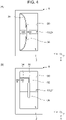
- Fig. 4(A) is a plan view of biasing part 26 according to modified example 1.
- biasing part 26 according to modified example 1 is a leaf spring having a curved shape protruding in first direction A from the edge extending in array direction X of opening 30.
- bus bar plate 6 is biased in second direction B by the reaction force in second direction B from projection 36.
- Fig. 4(B) is a plan view of biasing part 26 according to modified example 2.
- Modified example 2 is a modified example of biasing part 26 in a case where bus bar plate 6 is the second member and cell stack 2 is the first member. In the present modified example, biasing part 26 is provided on projection 36.
- Biasing part 26 has an approximately L shape, and includes arm 32 extending in array direction X and tip end 34 extending in horizontal direction Y. One end of arm 32 is connected to projection 36, and the other end of arm 32 is connected to one end of tip end 34. The other end of tip end 34 abuts on the edge extending in array direction X of opening 30. When arm 32 is elastically deformed, tip end 34 is displaced in horizontal direction Y. Tip end 34 presses the edge of opening 30 in first direction A, whereby bus bar plate 6 is biased in first direction A. On the other hand, cell stack 2 is biased in second direction B by the reaction force in second direction B from bus bar plate 6.
- biasing part 26 may have a shape extending linearly from a corner of opening 30 toward projection 36.
- Biasing part 26 may have a circular shape or a bellows shape when viewed in vertical direction Z, or may be a coil spring or the like. In this case, biasing part 26 is held between projection 36 and the edge extending in array direction X of opening 30.
- Biasing part 26 having a curved shape, a linear shape, a circular shape, a bellows shape, or a coil spring shape may be provided on either bus bar plate 6 or cell stack 2.
- battery module 1 includes: cell stack 2 in which the plurality of cells 8 each having output terminal 18 are arrayed; bus bar 4 that electrically connects output terminals 18 of cells 8 to each other, and bus bar plate 6 that covers the surface of cell stack 2 on which output terminal 18 is disposed, that has opening 22 at a position overlapping with respective output terminals 18, bus bar plate 6 in which bus bar 4 is disposed in opening 22.
- bus bar plate 6 and cell stack 2 is a first member and the other is a second member
- the first member has biasing part 26, and the second member has biasing receiver 28.
- the first member and the second member are biased in opposite directions to each other by biasing part 26 pressing the second member, and displacement of the first member and the second member is regulated by biasing receiver 28 abutting on the first member.
- Cell stack 2 of the present exemplary embodiment includes separator 10 disposed between two adjacent cells 8 to electrically insulate two cells 8 from each other, and biasing part 26 presses separator 10. Accordingly, it is possible to enhance positional accuracy between cell stack 2 and bus bar plate 6 without providing a separate member for positioning bus bar plate 6 with respect to cell stack 2.
- the second member of the present exemplary embodiment has projection 36 to be pressed by biasing part 26.
- projection 36 dedicated to receiving the biasing force from biasing part 26, it is possible to apply the biasing force of biasing part 26 to the second member more reliably.
- the magnitude of the biasing force can be more easily adjusted.
- Biasing receiver 28 of the present exemplary embodiment has plane 40, and plane 40 abuts on the first member to regulate displacement of the first member and the second member. This makes it possible to further enhance the positional accuracy of bus bar plate 6.
- two biasing parts 26 are arranged so as to hold biasing receiver 28 in array direction X. This makes it possible to position bus bar plate 6 more stably. Also when two biasing receivers 28 are arranged so as to hold biasing part 26 in array direction X, similarly bus bar plate 6 can be positioned stably.
- the second exemplary embodiment has a common configuration to the configuration of the first exemplary embodiment except that the pressing target of biasing part 26 is different.
- Fig. 5 is a plan view of battery module 1 according to the second exemplary embodiment.
- Fig. 6(A) is an enlarged plan view illustrating a region including biasing part 26 in battery module 1.
- Fig. 6(B) is an enlarged perspective view illustrating a region including biasing part 26 in battery module 1.
- bus bar plate 6 and cell stack 2 When one of bus bar plate 6 and cell stack 2 is a first member and the other is a second member, the first member has biasing part 26, and the second member has biasing receiver 28.
- bus bar plate 6 is the first member
- cell stack 2 is the second member. Note that bus bar plate 6 may be the second member, and cell stack 2 may be the first member.
- Biasing part 26 has an elastically deformable shape, and presses cell stack 2 as the second member by its elastic force in a state where bus bar plate 6 is placed on cell stack 2.
- biasing part 26 presses one of the pair of binding members 12. Therefore, binding member 12 is mating member 24 that is a direct biasing target of bus bar plate 6.
- biasing part 26 presses binding member 12, it is possible to enhance positional accuracy between cell stack 2 and bus bar plate 6 without providing a separate member for positioning bus bar plate 6.
- bus bar plate 6 as the first member and cell stack 2 as the second member are biased in opposite directions to each other.
- first direction A and second direction B are parallel to horizontal direction Y.
- biasing receiver 28 abuts on bus bar plate 6. This regulates displacement of bus bar plate 6 and cell stack 2.
- Bus bar plate 6 of the present exemplary embodiment has biasing parts 26 at both ends in array direction X on one end in horizontal direction Y.
- Biasing part 26 is a leaf spring having arm 32 extending in array direction X along the upper surface of cell stack 2 from a corner of body 6a of bus bar plate 6, and tip end 34 bent in first direction A from the tip end of arm 32 and extending toward binding member 12.
- Body 6a is a flat plate shaped part that expands in array direction X and horizontal direction Y and covers the upper surface of cell stack 2.
- Tip end 34 can be displaced in first direction A and second direction B by arm 32 bending with the based end in contact with the body 6a as a fulcrum.
- Binding member 12 has cutout 50 at a position opposing biasing part 26, and tip end 34 is fitted into cutout 50.
- tip end 34 presses binding member 12 in first direction A by the elastic deformation of arm 32, cell stack 2 is biased in first direction A.
- Bus bar plate 6 is biased in second direction B by the reaction force in second direction B from binding member 12.
- Biasing receiver 28 is provided on separator 10. Biasing receiver 28 protrudes in vertical direction Z from opening 30 provided at a center of bus bar plate 6 in array direction X and horizontal direction Y. Biasing receiver 28 abuts on bus bar plate 6 to regulate displacement of bus bar plate 6 in second direction B and displacement of cell stack 2 in first direction A.
- the aspect in which biasing receiver 28 and bus bar plate 6 abut on each other is similar to that in the first exemplary embodiment. Note that binding member 12 on the side opposite to binding member 12 pressed by biasing part 26 may function as biasing receiver 28.
- Biasing part 26 and biasing receiver 28 may be arrayed in array direction X.
- First direction A and second direction B may be parallel to array direction X.
- the modified example of the shape of biasing part 26 described in the first exemplary embodiment can also be applied to biasing part 26 of the second exemplary embodiment as long as it can exert an action of positioning cell stack 2 and bus bar plate 6.
- the number of cells 8 included in battery module 1 is not particularly limited.
- the structure of each part of battery module 1 including the shape of binding member 12 and the binding method for cell stack 2 by binding member 12 is not particularly limited.
Landscapes
- Chemical & Material Sciences (AREA)
- Chemical Kinetics & Catalysis (AREA)
- Electrochemistry (AREA)
- General Chemical & Material Sciences (AREA)
- Battery Mounting, Suspending (AREA)
- Connection Of Batteries Or Terminals (AREA)
Applications Claiming Priority (2)
| Application Number | Priority Date | Filing Date | Title |
|---|---|---|---|
| JP2020023782 | 2020-02-14 | ||
| PCT/JP2020/039439 WO2021161587A1 (ja) | 2020-02-14 | 2020-10-20 | 電池モジュール |
Publications (2)
| Publication Number | Publication Date |
|---|---|
| EP4106095A1 true EP4106095A1 (de) | 2022-12-21 |
| EP4106095A4 EP4106095A4 (de) | 2024-07-10 |
Family
ID=77292249
Family Applications (1)
| Application Number | Title | Priority Date | Filing Date |
|---|---|---|---|
| EP20918974.5A Pending EP4106095A4 (de) | 2020-02-14 | 2020-10-20 | Batteriemodul |
Country Status (5)
| Country | Link |
|---|---|
| US (1) | US20230067646A1 (de) |
| EP (1) | EP4106095A4 (de) |
| JP (1) | JP7608420B2 (de) |
| CN (1) | CN115004473A (de) |
| WO (1) | WO2021161587A1 (de) |
Families Citing this family (3)
| Publication number | Priority date | Publication date | Assignee | Title |
|---|---|---|---|---|
| KR20220075710A (ko) * | 2020-11-30 | 2022-06-08 | 에스케이온 주식회사 | 배터리 모듈 |
| JP7834061B2 (ja) * | 2023-07-04 | 2026-03-23 | プライムプラネットエナジー&ソリューションズ株式会社 | 電池パック |
| WO2026079253A1 (ja) * | 2024-10-10 | 2026-04-16 | 株式会社Honda・GS Yuasa EV Battery R&D | 蓄電装置 |
Family Cites Families (18)
| Publication number | Priority date | Publication date | Assignee | Title |
|---|---|---|---|---|
| US7875375B2 (en) * | 2004-08-05 | 2011-01-25 | Toyota Jidosha Kabushiki Kaisha | Battery module, battery pack, and method for producing the battery module |
| KR101041153B1 (ko) * | 2009-03-04 | 2011-06-13 | 에스비리모티브 주식회사 | 이차전지 및 그 모듈 |
| US20110293986A1 (en) * | 2009-11-25 | 2011-12-01 | Katsumi Kozu | Battery module |
| WO2011104792A1 (ja) * | 2010-02-24 | 2011-09-01 | パナソニック株式会社 | 電池パック |
| US20130273404A1 (en) * | 2010-10-30 | 2013-10-17 | Sanyo Electric., Ltd | Battery pack and vehicle including the same |
| JP5745938B2 (ja) | 2011-05-30 | 2015-07-08 | 株式会社東芝 | 二次電池装置 |
| JP5811396B2 (ja) * | 2011-08-02 | 2015-11-11 | 株式会社オートネットワーク技術研究所 | 電池配線モジュール |
| JP6104514B2 (ja) | 2012-03-14 | 2017-03-29 | 株式会社東芝 | 二次電池装置 |
| JP2015133169A (ja) * | 2012-04-27 | 2015-07-23 | 三洋電機株式会社 | 電源装置及びこれを備える車両並びに蓄電装置 |
| JP5850338B2 (ja) * | 2012-10-16 | 2016-02-03 | 住友電装株式会社 | 位置ずれ吸収部材及びバスバーユニット |
| KR102222888B1 (ko) | 2014-04-09 | 2021-03-04 | 삼성에스디아이 주식회사 | 배터리모듈 |
| JP6344362B2 (ja) * | 2015-10-23 | 2018-06-20 | 株式会社オートネットワーク技術研究所 | 蓄電モジュールおよび電池接続モジュール |
| JP6617009B2 (ja) * | 2015-11-16 | 2019-12-04 | 株式会社Gsユアサ | 蓄電装置、及びカバー部材 |
| CN107104211B (zh) * | 2016-02-23 | 2022-01-11 | 株式会社杰士汤浅国际 | 蓄电装置以及蓄电装置的制造方法 |
| JP2018133152A (ja) * | 2017-02-14 | 2018-08-23 | 日立オートモティブシステムズ株式会社 | 電池モジュール及び電池パック |
| JP6299917B1 (ja) | 2017-08-09 | 2018-03-28 | 株式会社オートネットワーク技術研究所 | 接続モジュール |
| JP6465196B1 (ja) | 2017-12-11 | 2019-02-06 | 株式会社オートネットワーク技術研究所 | 蓄電モジュール、及び接続モジュール |
| JP7006474B2 (ja) * | 2018-04-16 | 2022-01-24 | 株式会社オートネットワーク技術研究所 | 接続モジュールおよび蓄電モジュール |
-
2020
- 2020-10-20 WO PCT/JP2020/039439 patent/WO2021161587A1/ja not_active Ceased
- 2020-10-20 EP EP20918974.5A patent/EP4106095A4/de active Pending
- 2020-10-20 JP JP2022500225A patent/JP7608420B2/ja active Active
- 2020-10-20 CN CN202080094615.9A patent/CN115004473A/zh active Pending
- 2020-10-20 US US17/759,999 patent/US20230067646A1/en active Pending
Also Published As
| Publication number | Publication date |
|---|---|
| JPWO2021161587A1 (de) | 2021-08-19 |
| CN115004473A (zh) | 2022-09-02 |
| WO2021161587A1 (ja) | 2021-08-19 |
| US20230067646A1 (en) | 2023-03-02 |
| JP7608420B2 (ja) | 2025-01-06 |
| EP4106095A4 (de) | 2024-07-10 |
Similar Documents
| Publication | Publication Date | Title |
|---|---|---|
| EP3926732B1 (de) | Batteriemodul | |
| EP4106095A1 (de) | Batteriemodul | |
| JP6110336B2 (ja) | 蓄電モジュール | |
| US11171355B2 (en) | Binding member, and battery module | |
| US11171380B2 (en) | Binding member, and battery module | |
| EP4099351B1 (de) | Elektrisches speichermodul | |
| US20200388801A1 (en) | Battery module | |
| EP4199167A1 (de) | Stützstruktur | |
| US9159963B2 (en) | Secondary battery having first and second non-coated portions | |
| CN115298894B (zh) | 电池模块 | |
| CN112514148A (zh) | 电池模块的固定构造 | |
| US11996575B2 (en) | Energy storage apparatus | |
| US12203991B2 (en) | Support plate and voltage detection line module | |
| JP7799532B2 (ja) | 二次電池 | |
| EP4160633B1 (de) | Elektrisches energiespeichermodul | |
| EP4068319A1 (de) | Leistungsspeichermodul | |
| JP7809880B2 (ja) | 組電池 | |
| EP4203154A1 (de) | Batteriemodul | |
| WO2023145586A1 (ja) | 蓄電装置 |
Legal Events
| Date | Code | Title | Description |
|---|---|---|---|
| STAA | Information on the status of an ep patent application or granted ep patent |
Free format text: STATUS: THE INTERNATIONAL PUBLICATION HAS BEEN MADE |
|
| PUAI | Public reference made under article 153(3) epc to a published international application that has entered the european phase |
Free format text: ORIGINAL CODE: 0009012 |
|
| STAA | Information on the status of an ep patent application or granted ep patent |
Free format text: STATUS: REQUEST FOR EXAMINATION WAS MADE |
|
| 17P | Request for examination filed |
Effective date: 20220809 |
|
| AK | Designated contracting states |
Kind code of ref document: A1 Designated state(s): AL AT BE BG CH CY CZ DE DK EE ES FI FR GB GR HR HU IE IS IT LI LT LU LV MC MK MT NL NO PL PT RO RS SE SI SK SM TR |
|
| DAV | Request for validation of the european patent (deleted) | ||
| DAX | Request for extension of the european patent (deleted) | ||
| A4 | Supplementary search report drawn up and despatched |
Effective date: 20240612 |
|
| RIC1 | Information provided on ipc code assigned before grant |
Ipc: H01M 50/572 20210101ALI20240606BHEP Ipc: H01M 50/20 20210101ALI20240606BHEP Ipc: H01M 50/50 20210101AFI20240606BHEP |