EP4106490A1 - Induktionskochvorrichtung - Google Patents
Induktionskochvorrichtung Download PDFInfo
- Publication number
- EP4106490A1 EP4106490A1 EP21179396.3A EP21179396A EP4106490A1 EP 4106490 A1 EP4106490 A1 EP 4106490A1 EP 21179396 A EP21179396 A EP 21179396A EP 4106490 A1 EP4106490 A1 EP 4106490A1
- Authority
- EP
- European Patent Office
- Prior art keywords
- quasi
- induction
- resonant
- power board
- power
- Prior art date
- Legal status (The legal status is an assumption and is not a legal conclusion. Google has not performed a legal analysis and makes no representation as to the accuracy of the status listed.)
- Withdrawn
Links
- 230000006698 induction Effects 0.000 title claims abstract description 111
- 238000010411 cooking Methods 0.000 title claims abstract description 96
- 230000005672 electromagnetic field Effects 0.000 claims abstract description 11
- 235000013305 food Nutrition 0.000 claims abstract description 11
- 238000007669 thermal treatment Methods 0.000 claims abstract description 9
- 230000000712 assembly Effects 0.000 claims description 18
- 238000000429 assembly Methods 0.000 claims description 18
- 238000001514 detection method Methods 0.000 claims description 11
- 238000010438 heat treatment Methods 0.000 description 4
- 239000004615 ingredient Substances 0.000 description 3
- 239000003990 capacitor Substances 0.000 description 2
- 230000004048 modification Effects 0.000 description 2
- 238000012986 modification Methods 0.000 description 2
- 230000003247 decreasing effect Effects 0.000 description 1
- 239000003302 ferromagnetic material Substances 0.000 description 1
- 230000001939 inductive effect Effects 0.000 description 1
- 230000005291 magnetic effect Effects 0.000 description 1
- 239000000696 magnetic material Substances 0.000 description 1
- 238000004519 manufacturing process Methods 0.000 description 1
- 238000000034 method Methods 0.000 description 1
- 239000000203 mixture Substances 0.000 description 1
- 230000003068 static effect Effects 0.000 description 1
- 230000001360 synchronised effect Effects 0.000 description 1
Images

Classifications
-
- H—ELECTRICITY
- H05—ELECTRIC TECHNIQUES NOT OTHERWISE PROVIDED FOR
- H05B—ELECTRIC HEATING; ELECTRIC LIGHT SOURCES NOT OTHERWISE PROVIDED FOR; CIRCUIT ARRANGEMENTS FOR ELECTRIC LIGHT SOURCES, IN GENERAL
- H05B6/00—Heating by electric, magnetic or electromagnetic fields
- H05B6/02—Induction heating
- H05B6/06—Control, e.g. of temperature, of power
- H05B6/062—Control, e.g. of temperature, of power for cooking plates or the like
-
- H—ELECTRICITY
- H05—ELECTRIC TECHNIQUES NOT OTHERWISE PROVIDED FOR
- H05B—ELECTRIC HEATING; ELECTRIC LIGHT SOURCES NOT OTHERWISE PROVIDED FOR; CIRCUIT ARRANGEMENTS FOR ELECTRIC LIGHT SOURCES, IN GENERAL
- H05B2213/00—Aspects relating both to resistive heating and to induction heating, covered by H05B3/00 and H05B6/00
- H05B2213/03—Heating plates made out of a matrix of heating elements that can define heating areas adapted to cookware randomly placed on the heating plate
-
- Y—GENERAL TAGGING OF NEW TECHNOLOGICAL DEVELOPMENTS; GENERAL TAGGING OF CROSS-SECTIONAL TECHNOLOGIES SPANNING OVER SEVERAL SECTIONS OF THE IPC; TECHNICAL SUBJECTS COVERED BY FORMER USPC CROSS-REFERENCE ART COLLECTIONS [XRACs] AND DIGESTS
- Y02—TECHNOLOGIES OR APPLICATIONS FOR MITIGATION OR ADAPTATION AGAINST CLIMATE CHANGE
- Y02B—CLIMATE CHANGE MITIGATION TECHNOLOGIES RELATED TO BUILDINGS, e.g. HOUSING, HOUSE APPLIANCES OR RELATED END-USER APPLICATIONS
- Y02B40/00—Technologies aiming at improving the efficiency of home appliances, e.g. induction cooking or efficient technologies for refrigerators, freezers or dish washers
Definitions
- the present invention relates to an induction cooking appliance, in particular an induction cooking hob, for the thermal treatment of food products.
- Induction cooking appliances such as induction cooking hobs for the thermal treatment of food products are known household devices, which are conveniently efficient if compared with traditional gas or electric cooking appliances, because on the one side, they are accurate in controlling a cooking temperature and, on the other side, allow an uniform thermal treatment of the food product.
- Induction cooking appliances typically comprise: a support plate provided with at least one cooking zone designed to heat a load, i.e. a cooking vessel containing the food product, placed on the support plate.
- the cooking zone comprises an induction coil for generating a time-varying electro-magnetic field inducing eddy currents in the load.
- the internal resistances of the load cause the induced eddy currents to generate heat within the loads.
- the induction coil is powered by means of a power supply unit.
- the power supply unit comprises a generator operatively connected to the induction coil and configured to direct the required power to the respective induction coil.
- the power supply unit is configured to selectively control operation of the induction coils.
- induction cooking appliances having a plurality of induction coils, which are selectively controlled in order to dynamically define the cooking zone in function of the position of a cooking vessel being placed on the support plate.
- the first kind of induction cooking appliance is conveniently equipped with a single quasi-resonant generator, which, however, presents decreased performance characteristics in comparison to half-bridge generators.
- an induction cooking appliance according to the independent claim.
- an induction cooking appliance in particular an induction cooking hob, for the thermal treatment of food products comprising at least:
- the power supply unit comprises at least one power board assembly, the power board assembly being configured to selectively control a plurality of respective induction coils.
- Each power board assembly comprises at least a plurality of quasi-resonant generators, each one connected to at least one respective induction coil for controlling operation of the respective induction coil and one control unit coupled to the quasi-resonant generators and configured to control operation of the quasi-resonant generators.
- Each power board assembly comprises more than four quasi-resonant generators.
- each power board assembly only comprises generators of the quasi-resonant generator type.
- At least four induction coils are associated to each power board assembly.
- each quasi-resonant generator comprises a respective quasi-resonant inverter circuit having a single power switching device, in particular a single Insulated Gate Bipolar Transistor.
- each power board assembly comprises a plurality of drivers, each one coupled to the respective control unit and one respective quasi-resonant generator for driving the respective quasi-resonant generator.
- Each control unit is configured to selectively send control signals to the respective drivers and each driver is configured to drive the respective quasi-resonant generator in dependence of the control signal.
- each power board assembly comprises one power unit coupled and/or coupleable to an external power supply and the respective plurality of quasi-resonant generators and the respective induction coils.
- each power unit comprises a rectifier being coupled and/or coupleable to the external power supply and configured to convert an AC power signal provided by the external power supply into a rectified DC power signal.
- Each rectifier is coupled to the respective plurality of quasi-resonant generators and the respective plurality of induction coils.
- the rectifier conditions the external energy supply such that the quasi-resonant generators can correctly and precisely work.
- induction cooking appliance may further comprise a plurality of power board assemblies.
- the respective rectifier units are configured to be connected to the same main phase of the AC power signal and/or to different phases of the AC power signal.
- induction cooking appliance may also comprise:
- the control device is configured to control the power board assemblies as a function of the position of each load so as to energize these induction coils being adapted to interact with the loads.
- the detection unit is configured to detect a change of the position of one or more loads and the control device is configured to control the power board assemblies in dependence of the modified position or positions.
- each control unit comprises and/or consists of a microcontroller.
- the microcontroller allows a precise control of the quasi-resonant generators.
- number 1 indicates as a whole an induction cooking appliance, in particular an induction cooking hob, for the thermal treatment, in particular for the heating and/or cooking, of food products.
- the food product to be thermally treated may be a single ingredient or a mixture of ingredients. It should also be noted that the food product to be treated may vary throughout the overall thermal treatment process; i.e. it may be possible to add or remove ingredients to the food product during the thermal treatment.
- Induction cooking appliance 1 comprises at least:
- induction cooking appliance 1 may comprise a support plate 4, in particular having an horizontal orientation, being configured to support one or more loads, in particular one or more cooking vessels 5, to be heated.
- induction coils 3 are configured to generate the respective electromagnetic fields for generating eddy currents within cooking vessels 5.
- each cooking vessel 5 is adapted to be heated by means of induction heating.
- each cooking vessel 5 may comprise (,in particular may substantially consist of) a magnetic and/or ferromagnetic material.
- each cooking vessel 5 can be of any type and form.
- a non-exhaustive list of cooking vessels 5 are pans, pots and kettles.
- support plate 4 may comprise a first face 6 designed to carry cooking vessels 5 and a second face opposed to first face 6.
- induction coils 3 may be arranged such to face the second face.
- induction coils 3 may be arranged below support plate 4.
- induction cooking appliance 1 may comprise one or more cooking zones 7, each of which comprising at least one induction coil 2.
- each cooking zone 7 is defined by a respective support portion 8 of support plate 4 carrying, in use, the respective cooking vessel 5 to be heated, and one or more induction coils 2 being adapted to interact (through the respective electromagnetic field) with the respective cooking vessel 5, when, in use being arranged on the respective support portion 8.
- induction cooking appliance 1 may be designed to provide for dynamic cooking zones 7; i.e. each cooking zone 7 may be defined once the respective cooking vessel 5 is placed on support plate 4 and power supply unit 3 is designed to power induction coils 2 according to the position of the respective cooking vessel 5.
- Such a configuration also allows a modification of the respective cooking zone 7 if e.g. the position of the respective cooking vessel 5 is modified (see e.g. Figure 1 and the modification of the positioning of cooking vessel 5 from the center-left side of support plate 4 to the upper-right side) during the cooking process.
- cooking zones 7 could be static; i.e. each cooking zone 7 is defined by one respective fixed support portion 8 and one or more induction coils 2 being fixedly associated to the respective support portion 8.
- induction cooking appliance 1 may further comprise an user interface 9, in particular operatively coupled to power supply unit 3, designed to receive user input and/or providing information to the user.
- user interface 9 may be designed to receive user input relative to the energy input to be directed into induction coils 2.
- user interface 9 may be configured to receive a heating value/data indicative of a prefixed heating parameter, i.e. cooking temperature, selected by the user.
- user interface 9 may be placed within a portion of support plate 4.
- power supply unit 3 may be configured to selectively control induction coils 2 by respective AC currents.
- power supply unit 3 comprises one or more power board assemblies 13, each power board assembly 13 being configured to selectively control a plurality of respective induction coils 2.
- induction cooking appliance 1 could comprise less or more power board assemblies 13.
- each power board assembly 13 may comprise at least:
- each control unit 15 comprises and/or consists of one respective microcontroller.
- each control unit 15 is configured to selectively control the respective quasi-resonant generators 14 such that the respective quasi-resonant generators 14 control the respective induction coils 2, and in particular thereby the respective electromagnetic fields.
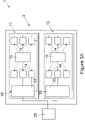
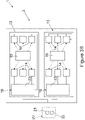
- each power board assembly 13 comprises more than four quasi-resonant generators 14. In the specific examples shown in Figures 3A and 3B , each power board assembly 13 comprises six quasi-resonant generators 14.
- the number of induction coils 2 can also be larger than four.
- power board assemblies 13 must not necessarily comprise the same number of quasi-resonant generators 14. Indeed, the number of quasi-resonant generators 14 may vary from one power board assembly 13 to the other.
- each power board assembly 13 may comprise up-to 10 or even more quasi-resonant generators 14.
- each power board assembly 13 only comprises generators of the quasi-resonant generator type (quasi-resonant generators 14); i.e. each power board assembly 13 does not comprise other types of generators adapted to command induction coils 2. It is clear that power board assemblies 13 comprise other components different from the quasi-resonant generators 14 such as the already introduced control unit 15, but no other type of generator.
- each quasi-resonant generator 14 comprises a respective quasi-resonant inverter circuit 16 having a single power switching device 17, in particular a single Insulated Gate Bipolar Transistor.
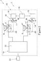
- Figure 2 depicts only two quasi-resonant generators 14 of the respective power board assembly 13.
- the other respective quasi-resonant generators 14 have been omitted for reasons of simplicity.
- each power board assembly 13 may comprise a plurality of drivers 18, each one coupled to the respective control unit 15 and one respective quasi-resonant generator 14.
- each driver 18 may be configured to control and/or drive the respective quasi-resonant generator 14. Even more particular each driver 18 may be controlled by means of the respective control unit 15 itself so as to control and/or drive the respective quasi-resonant generator 14.
- each control unit 15 may be configured to selectively send control signals to the respective drivers 18, in particular so that drivers 18 control, in use, the respective quasi-resonant generator 14 in dependence of the control signal.
- each power board assembly 13 may comprise one power unit 19 coupled and/or coupleable to an external power supply 20, the respective plurality of quasi-resonant generators 14 and the respective induction coils 2.
- external power supply 20 may be provided to a (residential) property from an energy production source such as an electric utility.
- External power supply 20 may e.g. correspond to a two phase (e.g. 220 volt) alternating current (AC) power supply.
- AC alternating current
- any other external power source 20 can be used such as for example, a one phase (110V) power supply, or a three phase power supply (380 V) and/or a DC power source.
- each power board assembly 13, in particular the respective power unit 19, is electrically connected to the same phase of external power supply 20.
- external power supply 20 may comprise a main phase 21 and at least one auxiliary phase 22.
- at least one power board assembly 13, in particular the respective power unit 19, may be connected to main phase 21 and at least another power board assembly 13 may be connected to auxiliary phase 22.
- each power unit 19 may comprise a rectifier 23 being coupled and/or coupleable to external power supply 20 and configured to convert an AC power signal provided by external power supply 20 into a rectified DC power signal.
- each rectifier 23 may comprise a diode full-bridge for full-wave rectification or a synchronous rectifier with a plurality of switching elements for active rectification and/or any similar rectification circuit.
- each rectifier 23 may be coupled to the respective plurality of quasi-resonant generators 14 and the respective plurality of induction coils 2.
- one or more rectifiers 23 may be configured to be connected to main phase 21 and one or more rectifiers 23 may be connected to auxiliary phase 22.
- induction cooking appliance 1 may comprise:
- control device is connected to each power board assembly 13, in particular the respective control unit 15, as a function of the position of cooking vessel 5 or cooking vessels 5 so as to energize these induction coils 3 being adapted to interact with the cooking vessel 5 or the cooking vessels 5 placed on support plate 4.
- control device controls power board assemblies 13
- one cooking vessel 5 interacts with induction coils 2 being controlled by means of quasi-resonant generators 14 of the same power board assembly 13 and/or one or more different power board assemblies 13.
- the detection unit may be configured to detect a change of the position of one or more cooking vessels 4.
- the control device may be configured to control each power board assembly 13 in dependence of the modified position or positions.
- power supply unit 9 may comprise a plurality of resonant capacitors 24, each one associated to one respective induction coil 3 so as to form in combination a respective resonator tank 25.
- a user places one or more cooking vessels 5 on support plate 4 and power supply unit 3 selectively controls the energy supply to induction coils 2 for generating the heat within the respective cooking vessel 5.
- control units 15 control operation of these induction coils 2, which needs to be energized so as to heat the respective cooking vessels 5.
- the detection unit allows to detect the position of cooking vessels 5 and the control device controls power board assemblies 13 according to the detected position(s).
Landscapes
- Physics & Mathematics (AREA)
- Electromagnetism (AREA)
- Induction Heating Cooking Devices (AREA)
Priority Applications (1)
| Application Number | Priority Date | Filing Date | Title |
|---|---|---|---|
| EP21179396.3A EP4106490A1 (de) | 2021-06-15 | 2021-06-15 | Induktionskochvorrichtung |
Applications Claiming Priority (1)
| Application Number | Priority Date | Filing Date | Title |
|---|---|---|---|
| EP21179396.3A EP4106490A1 (de) | 2021-06-15 | 2021-06-15 | Induktionskochvorrichtung |
Publications (1)
| Publication Number | Publication Date |
|---|---|
| EP4106490A1 true EP4106490A1 (de) | 2022-12-21 |
Family
ID=76483039
Family Applications (1)
| Application Number | Title | Priority Date | Filing Date |
|---|---|---|---|
| EP21179396.3A Withdrawn EP4106490A1 (de) | 2021-06-15 | 2021-06-15 | Induktionskochvorrichtung |
Country Status (1)
| Country | Link |
|---|---|
| EP (1) | EP4106490A1 (de) |
Citations (6)
| Publication number | Priority date | Publication date | Assignee | Title |
|---|---|---|---|---|
| EP2034800A1 (de) * | 2007-08-07 | 2009-03-11 | BSH Bosch und Siemens Hausgeräte GmbH | Kochvorrichtungsschaltung |
| EP2211591A1 (de) * | 2009-01-22 | 2010-07-28 | BSH Bosch und Siemens Hausgeräte GmbH | Verfahren zum Betreiben eines Kochfelds mit einer Mehrzahl von Heizelementen |
| US20120103971A1 (en) * | 2009-05-04 | 2012-05-03 | Lg Electronics Inc. | Cooking appliance and a control method thereof |
| EP2928265A1 (de) * | 2014-04-03 | 2015-10-07 | E.G.O. ELEKTRO-GERÄTEBAU GmbH | Induktionsheizvorrichtung und induktionskochfeld |
| EP2380400B1 (de) * | 2008-12-19 | 2015-10-14 | BSH Hausgeräte GmbH | Induktionskochfeld und verfahren zum betreiben eines induktionskochfelds |
| US10893579B2 (en) * | 2017-07-18 | 2021-01-12 | Whirlpool Corporation | Method for operating an induction cooking hob and cooking hob using such method |
-
2021
- 2021-06-15 EP EP21179396.3A patent/EP4106490A1/de not_active Withdrawn
Patent Citations (6)
| Publication number | Priority date | Publication date | Assignee | Title |
|---|---|---|---|---|
| EP2034800A1 (de) * | 2007-08-07 | 2009-03-11 | BSH Bosch und Siemens Hausgeräte GmbH | Kochvorrichtungsschaltung |
| EP2380400B1 (de) * | 2008-12-19 | 2015-10-14 | BSH Hausgeräte GmbH | Induktionskochfeld und verfahren zum betreiben eines induktionskochfelds |
| EP2211591A1 (de) * | 2009-01-22 | 2010-07-28 | BSH Bosch und Siemens Hausgeräte GmbH | Verfahren zum Betreiben eines Kochfelds mit einer Mehrzahl von Heizelementen |
| US20120103971A1 (en) * | 2009-05-04 | 2012-05-03 | Lg Electronics Inc. | Cooking appliance and a control method thereof |
| EP2928265A1 (de) * | 2014-04-03 | 2015-10-07 | E.G.O. ELEKTRO-GERÄTEBAU GmbH | Induktionsheizvorrichtung und induktionskochfeld |
| US10893579B2 (en) * | 2017-07-18 | 2021-01-12 | Whirlpool Corporation | Method for operating an induction cooking hob and cooking hob using such method |
Similar Documents
| Publication | Publication Date | Title |
|---|---|---|
| US9060389B2 (en) | Induction heating cooker | |
| EP2530999B1 (de) | Vorrichtung und System für Induktionsheizung | |
| KR101743495B1 (ko) | 유도가열 조리기기 | |
| EP3170363B1 (de) | System und verfahren zur verbesserung der rauschleistung eines mehrbereichs-quasiresonanter-umrichterinduktionsheizer | |
| EP2428733B1 (de) | Kochgerät | |
| JP2009094028A (ja) | 誘導加熱調理器 | |
| JPH0612699B2 (ja) | 誘導加熱調理器 | |
| AU2020316622B2 (en) | Method for controlling the provision of electric power to an induction coil | |
| EP3050398B1 (de) | Synchronisationsschaltung zur speisung der dualinduktionsspulenheizzone eines kochfeldes | |
| KR101729020B1 (ko) | 유도가열 조리기기 | |
| JP2001196156A (ja) | 誘導加熱調理器 | |
| KR101676452B1 (ko) | 유도가열 조리기기 | |
| KR20090005142U (ko) | 유도가열 조리기 | |
| KR101611277B1 (ko) | 유도가열 조리기기 | |
| EP3170362B1 (de) | System und verfahren zur änderung einer kochgeschirrposition in einem induktionsherd | |
| JP5058296B2 (ja) | 誘導加熱調理器 | |
| US20240284564A1 (en) | Induction cooking appliance | |
| JP5734390B2 (ja) | 誘導加熱調理器 | |
| WO2016010493A1 (en) | Induction heating cooker enabling improved power setting control | |
| JP4431346B2 (ja) | 誘導加熱調理器 | |
| US12301129B2 (en) | Power converting device and home appliance including the same | |
| EP4033858B1 (de) | Induktionsheizgerät und vorrichtung zur steuerung davon | |
| AU2020400849B2 (en) | Method and system to control a QR-inverter in a induction cooking appliance | |
| JP3201150B2 (ja) | ジャー炊飯器 | |
| CN114830823A (zh) | 用于控制感应烹饪器具中的qr逆变器的方法和系统 |
Legal Events
| Date | Code | Title | Description |
|---|---|---|---|
| PUAI | Public reference made under article 153(3) epc to a published international application that has entered the european phase |
Free format text: ORIGINAL CODE: 0009012 |
|
| STAA | Information on the status of an ep patent application or granted ep patent |
Free format text: STATUS: THE APPLICATION HAS BEEN PUBLISHED |
|
| AK | Designated contracting states |
Kind code of ref document: A1 Designated state(s): AL AT BE BG CH CY CZ DE DK EE ES FI FR GB GR HR HU IE IS IT LI LT LU LV MC MK MT NL NO PL PT RO RS SE SI SK SM TR |
|
| STAA | Information on the status of an ep patent application or granted ep patent |
Free format text: STATUS: THE APPLICATION IS DEEMED TO BE WITHDRAWN |
|
| 18D | Application deemed to be withdrawn |
Effective date: 20230622 |