EP4106571B1 - Sohle für einen laufschuh - Google Patents
Sohle für einen laufschuh Download PDFInfo
- Publication number
- EP4106571B1 EP4106571B1 EP21707215.6A EP21707215A EP4106571B1 EP 4106571 B1 EP4106571 B1 EP 4106571B1 EP 21707215 A EP21707215 A EP 21707215A EP 4106571 B1 EP4106571 B1 EP 4106571B1
- Authority
- EP
- European Patent Office
- Prior art keywords
- channels
- bottom layer
- midsole
- sole according
- layer
- Prior art date
- Legal status (The legal status is an assumption and is not a legal conclusion. Google has not performed a legal analysis and makes no representation as to the accuracy of the status listed.)
- Active
Links
Images
Classifications
-
- A—HUMAN NECESSITIES
- A43—FOOTWEAR
- A43B—CHARACTERISTIC FEATURES OF FOOTWEAR; PARTS OF FOOTWEAR
- A43B13/00—Soles; Sole-and-heel integral units
- A43B13/02—Soles; Sole-and-heel integral units characterised by the material
- A43B13/026—Composites, e.g. carbon fibre or aramid fibre; the sole, one or more sole layers or sole part being made of a composite
-
- A—HUMAN NECESSITIES
- A43—FOOTWEAR
- A43B—CHARACTERISTIC FEATURES OF FOOTWEAR; PARTS OF FOOTWEAR
- A43B13/00—Soles; Sole-and-heel integral units
- A43B13/02—Soles; Sole-and-heel integral units characterised by the material
- A43B13/12—Soles with several layers of different materials
-
- A—HUMAN NECESSITIES
- A43—FOOTWEAR
- A43B—CHARACTERISTIC FEATURES OF FOOTWEAR; PARTS OF FOOTWEAR
- A43B13/00—Soles; Sole-and-heel integral units
- A43B13/02—Soles; Sole-and-heel integral units characterised by the material
- A43B13/12—Soles with several layers of different materials
- A43B13/125—Soles with several layers of different materials characterised by the midsole or middle layer
- A43B13/127—Soles with several layers of different materials characterised by the midsole or middle layer the midsole being multilayer
-
- A—HUMAN NECESSITIES
- A43—FOOTWEAR
- A43B—CHARACTERISTIC FEATURES OF FOOTWEAR; PARTS OF FOOTWEAR
- A43B13/00—Soles; Sole-and-heel integral units
- A43B13/14—Soles; Sole-and-heel integral units characterised by the constructive form
- A43B13/143—Soles; Sole-and-heel integral units characterised by the constructive form provided with wedged, concave or convex end portions, e.g. for improving roll-off of the foot
- A43B13/145—Convex portions, e.g. with a bump or projection, e.g. 'Masai' type shoes
-
- A—HUMAN NECESSITIES
- A43—FOOTWEAR
- A43B—CHARACTERISTIC FEATURES OF FOOTWEAR; PARTS OF FOOTWEAR
- A43B13/00—Soles; Sole-and-heel integral units
- A43B13/14—Soles; Sole-and-heel integral units characterised by the constructive form
- A43B13/18—Resilient soles
- A43B13/181—Resiliency achieved by the structure of the sole
-
- A—HUMAN NECESSITIES
- A43—FOOTWEAR
- A43B—CHARACTERISTIC FEATURES OF FOOTWEAR; PARTS OF FOOTWEAR
- A43B13/00—Soles; Sole-and-heel integral units
- A43B13/14—Soles; Sole-and-heel integral units characterised by the constructive form
- A43B13/18—Resilient soles
- A43B13/181—Resiliency achieved by the structure of the sole
- A43B13/183—Leaf springs
-
- A—HUMAN NECESSITIES
- A43—FOOTWEAR
- A43B—CHARACTERISTIC FEATURES OF FOOTWEAR; PARTS OF FOOTWEAR
- A43B13/00—Soles; Sole-and-heel integral units
- A43B13/14—Soles; Sole-and-heel integral units characterised by the constructive form
- A43B13/18—Resilient soles
- A43B13/187—Resiliency achieved by the features of the material, e.g. foam, non liquid materials
Definitions
- the invention relates to the field of shoe technology, in particular for sports and leisure shoes, and concerns a sole for a running shoe.
- a sole is provided which, on the one hand, achieves a satisfactory cushioning effect, in particular in the horizontal and vertical directions, and at the same time reduces energy losses during the impression process and preferably provides additional energy for the impression process.
- a sole is provided which is lightweight.
- the general problem is solved by a sole for a running shoe with a midsole, wherein the midsole has a soft-elastic upper layer and a soft-elastic lower layer.
- a flexurally elastic, incompressible plate is arranged vertically between the upper layer and the lower layer.
- the lower layer has several channels running transversely across the midsole, which channels are vertically and/or horizontally deformable in the longitudinal direction under the action of vertically and/or longitudinally acting forces occurring during running.
- the channels of the lower layer are delimited by the soft-elastic lower layer and by the flexurally elastic, incompressible plate.
- the channels of the underlayer of the midsole are deformable vertically and/or horizontally in the longitudinal direction until closure under the effect of vertical and/or longitudinal forces occurring during running.
- the midsole is constructed in layers and can be described in some embodiments as a sandwich structure. From the bottom of the sole, or from the ground, the bottom layer is arranged first, followed by the flexurally elastic incompressible plate, and then the upper layer. The fact that the incompressible plate is thus arranged vertically between the upper layer and the bottom layer allows for a An arrangement above the midsole means that the plate in the sole can be bent more easily during the rolling process and has a lower bending moment, as the movement and the force emanating from the runner's foot are more efficiently transferred through the upper layer to the flexurally elastic, incompressible plate. This effect is further enhanced by the channels, as they make the midsole more flexible and easier to bend.
- the plate is taut during the rolling process and, due to its flexurally elastic, incompressible properties, provides a restoring force that supplies additional energy for the push-off process.
- the channels arranged in the lower layer enable an efficient and satisfactory cushioning effect.
- the longitudinal direction L of the sole is described by an axis from the heel region to the forefoot region and thus extends along the longitudinal axis of the sole.
- the transverse direction Q of the sole runs transversely to the longitudinal axis and substantially parallel to the underside of the sole, or substantially parallel to the ground.
- the transverse direction runs along a transverse axis of the midsole.
- the vertical direction V refers to a direction from the underside of the sole towards the insole, or in the operative state towards the wearer's foot, and thus runs along a vertical axis of the midsole.
- the inside of the midsole of a pair of running shoes refers to the outer region of the midsole along the longitudinal axis, which, in the case of one pair of running shoes, faces the second running shoe when worn.
- the outside of the midsole of a pair of running shoes refers to the outer region of the midsole along the longitudinal axis, which, in the case of a pair of running shoes, faces away from the second running shoe when worn and is thus arranged opposite the inside.
- the lateral area of the midsole refers to an area along the lateral inner and outer sides of the midsole of the running shoe of a pair of running shoes, The region extends in the direction of the longitudinal axis of the midsole.
- the horizontal extent of the lateral region is a few centimeters, for example, 0.1 to 5 cm, preferably 0.5 to 3 cm.
- the medial region of the midsole refers to an area along the longitudinal axis in the middle of the midsole, which extends in the transverse direction of the midsole.
- the horizontal extent of the medial region is a few centimeters, for example, 0.1 to 5 cm, preferably 0.5 to 3 cm.
- Soft-elastic materials for soles are well known to those skilled in the art. For example, materials with a Young's modulus of approximately 0.0001 to 0.2 GPa, in particular 0.001 to 0.1 GPa, can be used, which can be considered a soft-elastic material within the meaning of the present invention. Such materials can typically comprise polymer foams. Soft-elastic materials can include polyurethane, in particular thermoplastic polyurethane (TPU) or expanded thermoplastic polyurethane (eTPU), polyamides, e.g., PA-11, PA-12, nylon, polyethylene terephthalate (PET), or polybutylene terephthalate (PBT), or mixtures thereof.
- TPU thermoplastic polyurethane
- eTPU expanded thermoplastic polyurethane
- PA-11, PA-12 polyamides
- nylon polyethylene terephthalate
- PET polyethylene terephthalate
- PBT polybutylene terephthalate
- the forces that occur when running are typically due to the weight of the wearer, which can be between 40 and 120 kg, in particular between 50 and 100 kg.
- a channel in the sense of the present invention is understood to be a recess, which can typically be tubular. In general, a channel is wholly or partially delimited by channel walls. Typically, the channels are empty. In particular, the channels can be open and continuous, ie, a channel is preferably not a blind hole. In preferred embodiments, the channels of the lower layer can run substantially parallel to one another. In some embodiments, the total proportion of the open area of the midsole, ie, the total proportion of the lateral surfaces of the channel openings, be smaller than the total part of the closed surface of the midsole, ie the total part of the outer surface of the midsole that does not have channels.
- the deformability of the channels can include, for example, vertical convergence of the channel walls and/or longitudinal shearing of the channel.
- the upper and lower channel walls can touch under the action of the forces occurring during movement, causing the corresponding channel to deform until it is laterally closed.
- a channel wall can be formed by the flexible upper or lower layer and/or by the flexurally elastic, incompressible plate.
- the flexurally elastic, incompressible plate can be made of a hard polymer, e.g. LDPE, HDPE, polypropylene, polyether block amide (PEBA, for example PEBAX® ), etc. and/or of carbon fibers or mixtures thereof.
- the flexurally elastic, incompressible plate is therefore preferably made of a different material than the upper layer and the lower layer.
- a flexurally elastic plate within the meaning of the present invention can have a Young's modulus of 5 to 20 GPa, in particular 10 to 15 GPa, preferably 13 to 15 GPa.
- the flexurally elastic, incompressible plate can generally have a thickness, ie an extension in the vertical direction, of up to 5 mm, in particular 1 to 5 mm, preferably 1 to 3 mm.
- the thickness of the top layer in the vertical direction may be 0.3 to 2 cm.
- the upper layer may have multiple transverse channels. These channels further enhance the cushioning effect of the midsole and also make the upper layer more flexible, thus allowing the flexion of the flexurally elastic, incompressible plate is made easier and the rolling process is thus made easier. In addition, the energy of the impression is increased because the recovery of the plate bent during rolling is improved during the impression.
- the channels of the upper layer can run essentially parallel to one another. Typically, the channels of the lower layer and the upper layer are designed such that when walking in the longitudinal direction, the channel of the lower layer collapses first and only then the corresponding channel of the upper layer.
- the channels of the upper layer are vertically and/or horizontally deformable in the longitudinal direction under the effect of vertically and/or longitudinally acting forces that occur during walking.
- the channels of the upper layer are vertically and/or horizontally deformable in the longitudinal direction until they close under the effect of vertically and/or longitudinally acting forces that occur during walking.
- the channels of the upper layer can be offset horizontally in the longitudinal direction relative to the channels of the lower layer. This has the advantage that the cushioning can be distributed at least over the entire midfoot and heel area without the channels having to be overly large, which would render the sole unstable. Furthermore, due to the separation of the upper layer and lower layer by the flexurally elastic, incompressible plate, instabilities, particularly a floating effect, are avoided.
- the channels of the upper layer can be offset horizontally in the longitudinal direction relative to the channels of the lower layer such that the channels of the upper layer and the lower layer do not overlap in the vertical direction.
- no channel is preferably arranged in the upper layer above a channel in the lower layer and no channel is arranged in the lower layer below a channel in the upper layer, whereby the damping effect is further improved since the damping is not segmented and practically in all A cushioning effect is achieved in the relevant areas of the midsole.
- the flexibility of the midsole is increased during the rolling motion, as the channel walls in the upper layer narrow during the rolling motion, or the channels are closed, thus facilitating the bending of the flexurally elastic, incompressible plate.
- the channels of the topsheet are vertically and/or horizontally deformable in the longitudinal direction until closure under the action of vertically and/or longitudinally acting forces occurring during running.
- the channels of the upper layer and/or the lower layer have lateral openings in the lateral region of the midsole.
- the channels are preferably vertically and/or horizontally deformable in the longitudinal direction under the action of vertically and/or longitudinally acting forces occurring during walking until the lateral openings are closed.
- the channels in the upper layer and/or the lower layer are arranged at least in the heel region and the midfoot region. In some embodiments, the channels in the upper layer and/or the lower layer are arranged in the heel region, midfoot region, and forefoot region. In particular, the channels can be arranged longitudinally in the upper layer and/or the lower layer from the heel to the metatarsophalangeal joint of the wearer.
- the channels of the lower layer are formed entirely or partially by transversely oriented channel-shaped elements projecting downwards toward the floor. Only some of the channels of the lower layer, in particular a large part, or even all of the channels of the lower layer can be formed by channel-shaped elements. Such elements have the advantage that they are deformable and sealable, particularly horizontally in the longitudinal direction, and thus ensure good horizontal Provide cushioning, which is particularly gentle on the joints on downhill trails.
- the channel-shaped elements can be U-shaped in cross-section.
- the channel-shaped elements have a recess between them, which is arranged to make the midsole more flexible and to facilitate the rolling movement by reducing the bending moment of the flexurally elastic, incompressible plate in the sole.
- the channel-shaped elements can be arranged such that at least one recess is located below a channel in the upper layer, thereby facilitating the bending of the plate and thus the rolling movement.
- the recesses between the channel-shaped elements can define predetermined bending points of the midsole.
- the channels of the upper layer are delimited by the soft-elastic upper layer and by the flexurally elastic, incompressible plate.
- the channels of the lower layer are delimited by the soft-elastic lower layer and by the flexurally elastic, incompressible plate.
- the surface of the flexurally elastic, incompressible plate is at least partially exposed, or is directly exposed to the environment and thus only partially covered by the upper layer and/or the lower layer.
- the channels, which are partially delimited by the plate facilitate the bending of the plate during the rolling movement, as the compressive and tensile stresses on the plate are significantly reduced by the partial exposure of the plate due to the channels.
- Channels in the upper layer which are defined by the flexurally elastic incompressible plate, expose 10 to 30%, in particular 20 to 30%, preferably 25 to 30% of the surface of the flexurally elastic incompressible plate.
- the channels in the lower layer expose 10 to 35%, in particular 20 to 35%, preferably 25 to 35%, of the surface of the flexurally elastic incompressible plate. This significantly reduces the bending moment of the plate in the sole and enables efficient energy transfer.
- the flexurally elastic, incompressible plate extends substantially completely from the inside to the outside of the midsole.
- the incompressible plate can be directly exposed to the environment on the inside and/or outside and thus visible. The plate can thus completely separate the upper layer and the lower layer from each other. "Substantially completely” means that the plate extends over at least 90%, preferably at least 95%, preferably at least 98% of the area of the upper layer.
- the channels of the lower layer and/or the channels of the upper layer are elongated in cross-section along the longitudinal direction of the midsole.
- the height of the channels (extension in the vertical direction) is smaller than the width of the channels (extension in the longitudinal direction), thereby achieving a smaller overall thickness of the midsole and thus a reduction in the weight of the sole.
- the midsole has a groove extending longitudinally from the heel area to at least the midfoot area.
- the groove is thus located in the medial region of the sole.
- the groove enables a weight reduction of the sole, but on the other hand, due to its medial position, does not result in a significant reduction in the cushioning effect.
- the groove can extend vertically directly to the flexurally elastic, incompressible Plate so that it is partially exposed to the surroundings in the area of the groove and can therefore be seen from the underside of the sole.
- the groove Since there is no additional sole material in the area of the groove, the groove also facilitates the bending of the plate when walking by reducing the bending moment of the plate in the sole, which makes the rolling process more comfortable and increases support when taking a step.
- the groove is particularly preferably essentially V-shaped so that the lateral flanks of the groove are inclined. This prevents stones and pieces of wood from getting caught.
- the channels in the transverse direction of the underlayer can preferably be open towards the groove.
- a design in which the groove extends from the heel to the midfoot area has proven particularly advantageous.
- This groove allows for better deformability of the channels, which is particularly advantageous with thicker walls, such as those typically found in the heel and midfoot areas.
- a significantly weaker cushioning effect is typically required, which is why the channel walls in this area are thinner and thus more easily deformable than the channels in the heel and midfoot areas.
- the groove extends to the heel edge. This splits the soft, elastic midsole in the heel area. The two parts can move slightly apart in a transverse direction upon landing, further increasing the cushioning effect.
- the channels of the lower layer have a vertical height of 0.1 to 2.0 cm, preferably 0.2 to 1.0 cm, and the channels of the upper layer have a vertical height of 0.1 to 1.0 cm, preferably 0.2 to 0.5 cm.
- the height defines the distance between the respective channel walls in the vertical direction.
- the lower layer is attached to the flexurally elastic, incompressible plate.
- the lower layer can be glued or welded.
- the flexurally elastic, incompressible plate can also be attached to the upper layer by gluing or welding.
- At least one channel of the underlayer can have a front wall with a step in the area of the flexurally elastic, incompressible plate.
- the front wall typically refers to the wall of the channel that forms the front boundary of the channel in the longitudinal direction, i.e., in the running direction.
- the rear wall of the channel is the wall that forms the rear boundary of the channel in the longitudinal direction and is thus arranged closer to the heel edge of the running shoe.
- a step can be a first region of the front wall, which directly adjoins the flexurally elastic, incompressible plate and has a greater gradient than the adjoining second region of the front wall.
- the first region can be formed substantially perpendicular to the flexurally elastic, incompressible plate, e.g., at an angle of 80-90°.
- the adjacent second section of the front wall can form an angle of 35 to 60° to the flexurally elastic, incompressible plate.
- a step in the front wall facilitates horizontal shear and thus closure of the canal, efficiently absorbing horizontal forces.
- At least one channel of the lower layer can have a front wall and a rear wall, wherein the front wall is arranged at an angle to the flexurally elastic, incompressible plate that is smaller than the angle at which the rear wall of the channel is arranged to the flexurally elastic, incompressible plate. This facilitates horizontal shear and thus the closure of the channel, which improves the damping of horizontally acting forces.
- the midsole is curved upwards in the forefoot area in a vertical direction.
- the forefoot area can be curved upwards at an angle of 25 to 35° in the vertical direction. Since the flexurally elastic, incompressible plate is also curved upwards in the same way, the rolling motion is facilitated, i.e., the runner reaches the push-off position with less effort, in which only the forefoot area is in contact with the ground. This reduces energy loss and fatigue for the runner.
- the heel area of the midsole can be raised vertically toward the heel edge. This can improve the runner's initial contact with the ground and support the rolling motion, thus requiring less energy.
- the longitudinally rearmost channel of the midsole i.e., the channel closest to the heel edge of the midsole, is positioned such that it lies directly below the wearer's heel when worn. This achieves the greatest possible cushioning upon initial contact with the ground.
- the channel can be spaced 2 to 3.5 cm longitudinally from the heel edge, i.e., the rearmost edge of the midsole.
- the sole may comprise an outsole attached to the midsole, in particular directly to the underlayer.
- the outsole may have anti-slip properties.
- the outsole may be structured.
- the structuring may comprise regular or irregular grooves and/or furrows.
- the outsole can have cross structures. This ensures particularly good grip.
- the outsole is made of a different material than the midsole.
- the outsole can be made of an abrasion-resistant material such as TPU, polypropylene, or another suitable material.
- the outsole can preferably only be attached to a portion of the midsole, so that part of the midsole has no outsole.
- a structured outsole is provided in the lateral region of the outer side of the midsole, especially in the heel area, midfoot area, and forefoot area, since due to anatomical conditions, landing and imprint occur primarily in the lateral area on the outer side.
- at least a portion of the midsole, preferably in the midfoot area, in the lateral area on the inner side of the midsole can have no outsole. This can achieve significant time and cost savings during production without impairing the anti-slip properties of the sole.
- An outsole is typically also attached in the forefoot area of the midsole.
- the structuring of the outsole is designed such that in the lateral region of the lateral outer side, a structuring with sharper edges and/or a more pronounced structuring is provided than in the lateral region of the lateral inner side of the sole.
- the bottom layer and the top layer may not be directly connected to each other. Furthermore, the top layer may be completely separated from the bottom layer by the flexurally elastic, incompressible plate.
- the upper and lower layers are manufactured separately and are therefore not integral.
- the midsole may comprise at least two separate sole components: the upper layer and the lower layer.
- a further aspect of the invention relates to a running shoe comprising a sole according to one of the embodiments described here.
- a further aspect of the invention relates to the use of a sole according to one of the embodiments described here for the manufacture of a running shoe.
- an upper can be attached to the sole according to the invention, in particular sewn and/or glued.
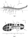
- the embodiment of a sole for a running shoe shown comprises a midsole 1 with a soft elastic upper layer 2 and a soft elastic Bottom layer 3.
- a flexibly elastic, incompressible plate 4 is arranged in the vertical direction V between the top layer 2 and the bottom layer 3. This results in a sandwich structure which, viewed from the bottom B, has the bottom layer 3 as the first layer, followed by the flexibly elastic, incompressible plate 4, and finally the top layer 2.
- the flexibly elastic, incompressible plate 4 thus generally forms an intermediate layer arranged between the top and bottom layers.
- the flexibly elastic, incompressible plate 4 extends essentially completely from the inside to the outside of the midsole 1 and is also visible from the outside.
- the plate thus essentially completely separates the top layer 2 from the bottom layer.
- the lower layer 3 has a plurality of channels 31a, 31b, 31c running in the transverse direction Q (for better clarity, the other channels are not labeled), which are vertically deformable (in the vertical direction V) and/or horizontally in the longitudinal direction L until they close under the action of forces acting vertically (in the vertical direction) and/or horizontally in the longitudinal direction L, which occur during running.
- the upper layer 2 also has a plurality of channels 21a, 21b, 21c running in the transverse direction Q (for better clarity, the other channels are not labeled), wherein at least some of the channels of the upper layer 2 are vertically deformable (in the vertical direction V) and/or horizontally in the longitudinal direction L until they close under the action of forces acting vertically (in the vertical direction) and/or horizontally in the longitudinal direction L, which occur during running.
- the channels 21a, 21b, 21c of the upper layer 2 are arranged offset horizontally in the longitudinal direction L relative to the channels 31a, 31b, 31c of the lower layer 3, in such a way that the channels of the upper layer do not overlap with the channels of the lower layer in the vertical direction V.
- the channels 31b, 31c of the lower layer 3 are formed by channel-shaped elements 32a and 32b. In cross section, the channel-shaped elements 32a, 32b, 32c are substantially U-shaped.
- the The angle formed by the flexible, incompressible plate 4 and the front wall of the respective channels is smaller than the angle formed by the flexible, incompressible plate and the rear wall of the respective channels.
- the channel-shaped elements 32a and 32b have a recess 33a between them, which is designed to make the midsole more flexible for the rolling movement.
- the recess 33a is arranged in the vertical direction V below the channel 21c of the upper layer 2, which further facilitates the rolling movement and the bending of the flexible, incompressible plate, since the recess 33a defines a predetermined bending point and the channel 21c closes or can be closed when the plate 4 is bent in the vertical direction and/or in the longitudinal direction.
- the channels of the upper layer 2 and the lower layer 3 in the Figure 1 shown embodiment are delimited by the flexurally elastic incompressible plate 4, whereby the plate is partially exposed.
- the channels 21a, 21b and 21c of the upper layer are delimited in the vertical direction at their respective undersides by the plate 4 and the channels 31a, 31b and 31c are delimited in the vertical direction at their respective upper side by the plate 4.
- the flexurally elastic incompressible plate 4 is formed by the flexurally elastic incompressible plate 4.
- both the channels 21a, 21b and 21c of the upper layer 2 and the channels 31a, 31b, 31c of the lower layer are shown to be elongated, ie the channel walls are spaced apart from one another at a greater distance in the longitudinal direction L than in the vertical direction V.
- the midsole 1 is bent upwards in the forefoot area at an angle of 25 to 35° relative to the ground B in the vertical direction V.
- the heel area of the midsole is raised in the vertical direction V.
- Channel 31a which is the channel of the lower layer 3 closest to the heel edge 5, is arranged such that it lies directly below the wearer's heel when worn.
- FIG. 2 is the underside of a midsole 1 facing the ground when worn, comprising the heel area FB, midfoot area MFB and forefoot area VFB.
- the outsole 7 is attached to a part of the midsole 1, or rather to the underlayer 3. It can be seen that no outsole is attached in the midfoot area, the midsole in the lateral area on the lateral inside of the midsole.
- the outsole 7 is structured.
- the structuring is designed as a cross structure. In the lateral area of the lateral outside, a structuring with sharper edges and a more pronounced structuring is provided than in the lateral area of the lateral inside of the sole.
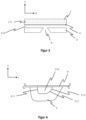
- FIG 3 is a cross-section in the transverse direction Q along the channel 31b extending in the transverse direction Q (see AA in Figure 2 ).
- the groove 6 is essentially V-shaped, and the channel 31b in the lower layer 3 is open towards the groove 6.
- the sandwich structure consisting of the lower layer 3, the flexurally elastic, incompressible plate 4, and the upper layer 2 is also visible.
- the flexurally elastic, incompressible plate 4 is arranged in the vertical direction V between the upper layer and the lower layer of the midsole 1.
- the channel 21c of the upper layer 2, which is not visible in the cross-section, is indicated by dashed lines.
- the channel 31b has a rear wall 311 and a front wall 312.
- the front wall 312 of the channel 31b has a step 313, which divides the front wall into a first and a second region.
- the first region which directly adjoins the flexurally elastic, incompressible plate 4, is essentially perpendicular to the plate 4.
- the second region of the front wall 312, which adjoins the first region at the step 313, is arranged at a smaller angle to the flexurally elastic, incompressible plate 4 than the first region.
Landscapes
- Chemical & Material Sciences (AREA)
- Engineering & Computer Science (AREA)
- Materials Engineering (AREA)
- Footwear And Its Accessory, Manufacturing Method And Apparatuses (AREA)
Description
- Die Erfindung bezieht sich auf das Gebiet der Schuhtechnik, insbesondere für Sport- und Freizeitschuhe und betrifft eine Sohle für einen Laufschuh.
- Im Stand der Technik ist eine Vielzahl von Laufschuhen mit verschiedenen Dämpfungssystemen bekannt. Weit verbreitet sind Sport- und Freizeitschuhe mit Sohlen, welche im Fersenbereich einen Gelkern zur Gewährleistung einer vertikalen Dämpfung beim Auftritt aufweisen. Des Weiteren wurden Verbesserungen der vertikalen Dämpfungseigenschaften dadurch erreicht, dass einzelne Federelemente im Fersenbereich zwischen Lauf- und Brandsohle angebracht wurden.
- Während durch die oben genannten Sohlen zwar die vertikalen Dämpfungseigenschaften der Schuhe verbessert wird, kann jedoch keine zufriedenstellende Dämpfung von horizontal auf die Sohle und den Schuh wirkenden Kräfte erreicht werden. Kräfte mit einem grossen horizontalen Anteil werden insbesondere auf abwegigen Strecken zusätzlich verstärkt und stellen mangels ausreichender Dämpfung eine der Hauptursachen für häufig auftretende Knie- und Hüftgelenkschmerzen dar.
- Aus der
WO 2016 184 920 der Anmelderin ist eine Sohle bekannt, welche nach unten vorstehende, seitlich offene, segmentierte und rinnenförmige Elemente aufweist. Unter der Wirkung der beim Laufen auftretenden Kräfte sind die rinnenförmigen Elemente bis zum Verschluss ihrer seitlichen Öffnungen sowohl vertikal als auch horizontal verformbar. Durch die Segmentierung der Sohle wird die Dämpfungswirkung ebenfalls segmentiert, wodurch nicht gedämpfte oder weniger gedämpfte Bereiche in der Sohle ausgebildet werden. - Die
US 6 205 681 B1 ,US 2019 289 961 A1 undUS 6 389 713 B1 offenbaren weitere im Stand der Technik bekannte Sohlen. - Bei vielen sportlichen Aktivtäten, wie beispielsweise dem Laufsport, erfolgt der Erstkontakt des Schuhs mit dem Boden im Fersenbereich. Hierdurch sind die auf den Schuh wirkenden Kräfte in diesem Bereich deutlich grösser als im Vorder- oder Mittelfussbereich der Sohle. Um diesem Umstand Rechnung zu tragen, weisen Laufschuhe im Allgemeinen eine besonders ausgeprägte Dämpfung im Fersenbereich auf. Eine solche Konstruktion erlaubt es zwar zumindest eine ausreichende vertikale Dämpfung zu gewährleisten, jedoch wirkt sich die ausgeprägte Dämpfung negativ auf das Gesamtgewicht des Schuhs aus. Dies hat zur Folge, dass die im Stand der Technik bekannten Laufschuhe entweder eine unzufriedenstellende Dämpfungswirkung und/oder ein hohes Gewicht aufweisen.
- Des Weiteren kann mit bekannten Dämpfungssystemen eine zufriedenstellende Dämpfungswirkung gewährleistet werden, allerdings führen solche Dämpfungssysteme aufgrund der weichen Komponenten, wie beispielsweise Gelkerne oder weichelastische Schäume, zu einem Energieverlust beim Abroll- und Abdruckvorgang des Läufers. Auf diese Weise muss bei jedem Schritt zusätzliche Energie für den Abdruck aufgewendet werden, was zu einer schnelleren Ermüdung des Läufers führen kann. Dieser Effekt verstärkt sich mit zunehmender Weichheit der Mittelsohle. Ein Problem des Stands der Technik ist es daher, einen Kompromiss zwischen der Weichheit der Mittelsohle zur Erhöhung der Dämpfungswirkung beim Auftritt und der Steifheit der Mittelsohle zur Vermeidung von Energieverlusten beim Abdruck zu finden.
- Es ist daher die allgemeine Aufgabe der Erfindung, den Stand der Technik im Bereich der Sohlen für Laufschuhe weiterzuentwickeln und vorzugsweise ein oder mehrere Nachteile des Standes der Technik zu überwinden.
- In einigen Ausführungsformen wird eine Sohle bereitgestellt, welche einerseits eine zufriedenstellende Dämpfungswirkung, insbesondere in horizontaler und vertikaler Richtung, erreicht und gleichzeitig beim Abdruckvorgang Energieverluste vermindert und vorzugsweise zusätzliche Energie für den Abdruckvorgang bereitstellt.
- In einigen Ausführungsformen wird eine Sohle bereitgestellt, welche ein geringes Gewicht aufweist.
- Gemäss einem ersten Aspekt der Erfindung wird die allgemeine Aufgabe durch eine Sohle für einen Laufschuh mit einer Mittelsohle gelöst, wobei die Mittelsohle eine weichelastische Oberschicht und eine weichelastische Unterschicht aufweist. Zudem ist in vertikaler Richtung zwischen der Oberschicht und der Unterschicht eine biegeelastische inkompressible Platte angeordnet. Die Unterschicht weist mehrere in Querrichtung der Mittelsohle verlaufende Kanäle auf, welche unter der Wirkung von vertikal und/oder in Längsrichtung wirkenden beim Laufen auftretenden Kräften vertikal und/oder horizontal in Längsrichtung verformbar sind. Die Kanäle der Unterschicht sind durch die weichelastische Unterschicht und durch die biegeelastische inkompressible Platte begrenzt. Durch die Kanäle der Unterschicht liegen 10 bis 35%, insbesondere 20 bis 35% vorzugsweise 25 bis 35% der Oberfläche der biegeelastischen inkompressiblen Platte frei. Vorzugsweise sind die Kanäle der Unterschicht der Mittelsohle unter der Wirkung von vertikal und/oder in Längsrichtung wirkenden beim Laufen auftretenden Kräften bis zum Verschluss vertikal und/oder horizontal in Längsrichtung verformbar.
- Der Aufbau der Mittelsohle ist schichtweise und kann in einigen Ausführungsformen als Sandwich-Struktur beschrieben werden. Von der Unterseite der Sohle, bzw. vom Boden aus gesehen ist zuerst die Unterschicht, dann die biegeelastische inkompressible Platte und dann die Oberschicht angeordnet. Dass die inkompressible Platte somit in vertikaler Richtung zwischen der Oberschicht und der Unterschicht angeordnet ist, ermöglicht im Vergleich zu einer Anordnung oberhalb der Mittelsohle, dass die Platte in der Sohle beim Abrollvorgang leichter gebogen werden kann bzw. ein geringeres Biegemoment aufweist, da die Bewegung und die vom Fuss des Läufers ausgehende Kraft effizienter durch die Oberschicht auf die biegeelastische inkompressible Platte übertragen wird. Dieser Effekt wird durch die Kanäle zusätzlich verstärkt, da hierdurch die Mittelsohle flexibler wird und leichter gebogen werden kann. Somit wird die Platte während des Abrollvorgangs gespannt und stellt aufgrund ihrer biegeelastischen inkompressiblen Eigenschaften eine Rückstellkraft zur Verfügung, welche zusätzliche Energie für den Abdruckvorgang bereitstellt. Gleichzeitig ermöglichen die in der Unterschicht angeordneten Kanäle eine effiziente und zufriedenstellende Dämpfungswirkung.
- Richtungsangaben, wie sie in der vorliegenden Offenbarung verwendet werden, sind wie folgt zu verstehen: Die Längsrichtung L der Sohle wird durch eine Achse vom Fersenbereich zum Vorderfussbereich beschrieben und erstreckt sich somit entlang der Längsachse der Sohle. Die Querrichtung Q der Sohle verläuft quer zur Längsachse und im Wesentlichen parallel zur Unterseite der Sohle, beziehungsweise im Wesentlichen parallel zum Boden. Somit verläuft die Querrichtung entlang einer Querachse der Mittelsohle. Die vertikale Richtung V bezeichnet im Zusammenhang mit der vorliegenden Erfindung eine Richtung von der Unterseite der Sohle in Richtung der Brandsohle, beziehungsweise im operativen Zustand in Richtung des Fusses des Trägers und verläuft somit entlang einer Vertikalachse der Mittelsohle. Die Innenseite der Mittelsohle eines Laufschuhpaares bezeichnet den äusseren Bereich der Mittelsohle entlang der Längsachse, welcher bei einem Laufschuhpaar im getragenen Zustand dem zweiten Laufschuh zugewandt ist. Dementsprechend bezeichnet die Aussenseite der Mittelsohle eines Laufschuhpaares den äusseren Bereich der Mittelsohle entlang der Längsachse, welcher bei einem Laufschuhpaar im getragenen Zustand dem zweiten Laufschuh abgewandt und damit gegenüberliegend zur Innenseite angeordnet ist. Des Weiteren bezeichnet der laterale Bereich der Mittelsohle einen Bereich entlang der seitlichen Innen- und Aussenseiten der Mittelsohle des Laufschuhs eines Laufschuhpaars, wobei sich der Bereich in Richtung der Längsachse der Mittelsohle erstreckt. Typischerweise liegt die horizontale Ausdehnung des lateralen Bereichs bei einigen Zentimetern, beispielsweise 0.1 bis 5 cm, vorzugsweise 0.5 bis 3 cm. Der mediale Bereich der Mittelsohle bezeichnet einen Bereich entlang der Längsachse in der Mitte der Mittelsohle, welcher sich jeweils in Querrichtung der Mittelsohle erstreckt. Typischerweise liegt die horizontale Ausdehnung des medialen Bereichs bei einigen Zentimetern, beispielsweise 0.1 bis 5 cm, vorzugsweise 0.5 bis 3 cm.
- Dem Fachmann sind weichelastische Materialien für Sohlen hinlänglich bekannt. Beispielsweise können Materialien mit einem Young Modul von etwa 0.0001 bis 0.2 GPa, insbesondere 0.001 bis 0.1 GPa verwendet werden, was im Sinne der vorliegenden Erfindung als weichelastisches Material angesehen werden kann. Typischerweise können solche Materialien Polymerschäume umfassen. Als weichelastische Materialien können Polyurethan, insbesondere thermoplastisches Polyurethan (TPU) oder expandiertes thermoplastisches Polyurethan (eTPU), Polyamide, z.B. PA-11, PA-12, Nylon, Polyethylenterephthalat (PET) oder Polybutylenterephthalat (PBT) oder Mischungen daraus, eingesetzt werden.
- Die beim Laufen auftretenden Kräfte sind typischerweise auf die Gewichtskraft ausgehend vom Gewicht des Trägers zurückzuführen, welches beispielsweise zwischen 40 und 120 kg, insbesondere zwischen 50 und 100 kg, betragen kann.
- Unter einem Kanal ist im Sinne der vorliegenden Erfindung eine Ausnehmung zu verstehen, welche typischerweise röhrenförmig ausgebildet sein kann. Im Allgemeinen wird ein Kanal durch Kanalwände ganz oder teilweise begrenzt. Typischerweise sind die Kanäle leer. Insbesondere können die Kanäle geöffnet und durchgehend sein, d.h. ein Kanal ist vorzugsweise kein Blindloch. In bevorzugten Ausführungsformen können die Kanäle der Unterschicht im Wesentlichen parallel zueinander verlaufen. In einigen Ausführungsformen kann der Gesamtanteil der geöffneten Fläche der Mittelsohle, d.h. der Gesamtanteil der seitlichen Flächen der Kanalöffnungen, kleiner sein als der Gesamtteil der geschlossenen Fläche der Mittelsohle, d.h. der Gesamtteil der äusseren Fläche der Mittelsohle, der keine Kanäle aufweist.
- Es ist dem Fachmann klar, dass die Verformbarkeit der Kanäle beispielsweise das vertikale Zusammenführen der Kanalwände und/oder die Scherung des Kanals in Längsrichtung umfassen kann. Typischerweise können sich die obere und die untere Kanalwand unter Wirkung der beim Laufen auftretenden Kräfte berühren, sodass die der entsprechende Kanal bis zum seitlichen Verschluss verformt wird. Eine Kanalwand kann dabei von der weichelastischen Ober- oder Unterschicht und/oder von der biegeelastischen inkompressiblen Platte gebildet werden.
- Die biegeelastische inkompressible Platte kann aus einem Hartpolymer, z.B. LDPE, HDPE, Polypropylen, Polyetherblockamid (PEBA, beispielsweise PEBAX®) etc. und/oder aus Carbonfasern oder Mischungen daraus, bestehen. Vorzugsweise ist die biegeelastische inkompressible Platte somit aus einem anderen Material wie die Oberschicht und die Unterschicht. Eine biegeelastische Platte im Sinne der vorliegenden Erfindung kann dabei ein Young Modul von 5 bis 20 GPa, insbesondere 10 bis 15 GPa, bevorzugt 13 bis 15 GPa aufweisen. Die biegeelastische inkompressible Platte kann im Allgemeinen eine Dicke, d.h. eine Ausdehnung in vertikaler Richtung von bis zu 5 mm, insbesondere 1 bis 5 mm, vorzugsweise 1 bis 3 mm aufweisen.
- In einigen Ausführungsformen kann die Dicke der Oberschicht in vertikaler Richtung 0.3 bis 2 cm betragen.
- In einigen Ausführungsformen kann die Oberschicht mehrere in Querrichtung verlaufende Kanäle aufweisen. Durch diese Kanäle wird einerseits die Dämpfungswirkung der Mittelsohle zusätzlich verbessert und andererseits wird die Oberschicht flexibler, wodurch das Biegen der biegeelastischen inkompressiblen Platte erleichtert und damit der Abrollvorgang erleichtert wird. Zudem wird die Energie des Abdrucks erhöht, da die Rückstellung der während des Abrollens gebogenen Platte beim Abdruck verbessert wird. In bevorzugten Ausführungsformen können die Kanäle der Oberschicht im Wesentlichen parallel zueinander verlaufen. Typischerweise sind die Kanäle der Unterschicht und der Oberschicht derart ausgebildet, dass beim Laufen in Längsrichtung gesehen zuerst der Kanal der Unterschicht kollabiert und erst dann der entsprechende Kanal der Oberschicht. Typischerweise sind die Kanäle der Oberschicht unter der Wirkung von vertikal und/oder in Längsrichtung wirkenden, beim Laufen auftretenden Kräften vertikal und/oder horizontal in Längsrichtung verformbar. Vorzugsweise sind die Kanäle der Oberschicht unter der Wirkung von vertikal und/oder in Längsrichtung wirkenden, beim Laufen auftretenden Kräften bis zum Verschluss vertikal und/oder horizontal in Längsrichtung verformbar.
- In weiteren Ausführungsformen können die Kanäle der Oberschicht zu den Kanälen der Unterschicht horizontal in Längsrichtung zueinander versetzt angeordnet sein. Dies hat den Vorteil, dass die Dämpfung zumindest über den gesamten Mittelfussbereich und Fersenbereich verteilt angeordnet werden kann, ohne dass die Kanäle übermässig gross dimensioniert werden müssen, wodurch die Sohle instabil werden würde. Aufgrund der Trennung der Oberschicht und Unterschicht durch die biegeelastische inkompressible Platte, werden zudem Instabilitäten, insbesondere ein Schwimmeffekt, vermieden.
- In einigen Ausführungsformen können die Kanäle der Oberschicht zu den Kanälen der Unterschicht derart horizontal in Längsrichtung zueinander angeordnet versetzt sein, dass sich die Kanäle der Oberschicht und der Unterschicht in vertikaler Richtung nicht überschneiden. In solchen Ausführungsformen ist daher vorzugsweise oberhalb eines Kanals in der Unterschicht kein Kanal in der Oberschicht angeordnet und unterhalb eines Kanals in der Oberschicht kein Kanal in der Unterschicht angeordnet, wodurch die Dämpfungswirkung zusätzlich verbessert wird, da die Dämpfung nicht segmentiert und praktisch in allen relevanten Bereichen der Mittesohle eine Dämpfungswirkung erreicht wird. Zudem wird die Flexibilität der Mittelsohle bei der Abrollbewegung erhöht, da sich die Kanalwände in der Oberschicht bei der Abrollbewegung verengen, bzw. die Kanäle verschlossen werden und damit das Biegen der biegeelastischen inkompressiblen Platte erleichtern.
- Typischerweise ist zumindest ein Teil der, oder alle Kanäle der Oberschicht unter der Wirkung von vertikal und/oder in Längsrichtung wirkenden, beim Laufen auftretenden Kräften bis zum Verschluss vertikal und/oder horizontal in Längsrichtung verformbar.
- In einigen Ausführungsformen weisen die Kanäle der Oberschicht und/oder der Unterschicht seitliche Öffnungen im lateralen Bereich der Mittelsohle auf. Vorzugsweise sind die Kanäle unter der Wirkung von vertikal und/oder in Längsrichtung wirkenden, beim Laufen auftretenden Kräften bis zum Verschluss der seitlichen Öffnungen vertikal und/oder horizontal in Längsrichtung verformbar.
- In weiteren Ausführungsformen sind die Kanäle in der Oberschicht und/oder der Unterschicht zumindest im Fersenbereich und im Mittelfussbereich angeordnet. In einigen Ausführungsformen sind die Kanäle in der Oberschicht und/oder der Unterschicht im Fersenbereich, Mittelfussbereich und Vorderfussbereich angeordnet. Insbesondere können die Kanäle von der Ferse bis zum Zehengrundgelenk des Trägers in Längsrichtung in der Oberschicht und/oder der Unterschicht angeordnet sein.
- In einigen Ausführungsformen werden die Kanäle der Unterschicht ganz oder teilweise durch in Querrichtung ausgerichtete, nach unten gegen den Boden vorstehende rinnenförmige Elemente gebildet. Hierbei können nur ein Teil der Kanäle der Unterschicht, insbesondere ein Grossteil, oder auch alle Kanäle der Unterschicht durch rinnenförmige Elemente gebildet werden. Solche Elemente haben den Vorteil, dass sie insbesondere horizontal in Längsrichtung verformbar und verschliessbar sind und dadurch eine gute horizontale Dämpfung bereitstellen, was besonders auf absteigenden Wegen eine gelenkschonende Wirkung hat. Die rinnenförmigen Elemente können dabei im Querschnitt U-förmig ausgebildet sein. Vorzugsweise weisen die rinnenförmigen Elemente zwischen einander eine Aussparung auf, welche dazu angeordnet ist, die Mittelsohle flexibler zu machen und die Abrollbewegung durch Verringerung des Biegemoments der biegeelastischen inkompressiblen Platte in der Sohle zu erleichtern. Bevorzugt können die rinnenförmigen Elemente dabei derart angeordnet sein, dass mindestens eine Aussparung unterhalb eines Kanals der Oberschicht angeordnet ist, wodurch das Biegen der Platte und damit der Abrollbewegung erleichtert wird. Die Aussparungen zwischen den rinnenförmigen Elementen können Sollbiegestellen der Mittelsohle definieren.
- In einigen Ausführungsformen sind die Kanäle der Oberschicht durch die weichelastische Oberschicht und durch die biegeelastische inkompressible Platte begrenzt. Die Kanäle der Unterschicht sind durch die weichelastische Unterschicht und durch die biegeelastische inkompressible Platte begrenzt. Hierdurch wird die Oberfläche der biegeelastischen inkompressiblen Platte zumindest teilweise freigelegt, bzw. ist direkt der Umgebung exponiert und damit nur teilweise direkt von der Oberschicht und/oder der Unterschicht bedeckt. Die Kanäle, welche teilweise durch die Platte begrenzt werden, erleichtern so das Biegen der Platte bei der Abrollbewegung, da die Druck- und Zugspannungen auf die Platte durch die teilweise Freistellung der Platte aufgrund der Kanäle wesentlich verringert wird. Hierdurch wird einerseits eine effizientere Energieübertragung beim Abdruck ermöglicht und andererseits können steifere Platten verwendet werden, als es ohne solche Kanäle möglich wäre. Ohne solche Kanäle würden relativ steife Platten dazu führen, dass die Platte nicht mehr bei einer normalen Laufbewegung ohne Weiteres gebogen werden könnte, was den Laufkomfort deutlich reduzieren würde. Die Verwendung von steiferen Platten hat jedoch den Vorteil, dass die für den Abdruck bereitstellbare Energie entsprechend höher ist. Zudem ermöglicht ein solcher Aufbau eine geringere Gesamtdicke der Mittelsohle, was deren Gewicht wesentlich reduziert. Insbesondere können durch die
- Kanäle in der Oberschicht, welche durch die biegeelastische inkompressible Platte begrenzt sind 10 bis 30%, insbesondere 20 bis 30%, vorzugsweise 25 bis 30% der Oberfläche der biegeelastische inkompressible Platte freiliegen. Durch die Kanäle der Unterschicht liegen 10% bis 35%, insbesondere 20 bis 35% vorzugsweise 25 bis 35% der Oberfläche der biegeelastischen inkompressiblen Platte frei.. Hierdurch wird das Biegemoment der Platte in der Sohle signifikant verringert und eine effiziente Energieübertragung ermöglicht.
- In weiteren Ausführungsformen erstreckt sich die biegeelastische inkompressible Platte im Wesentlichen vollständig von der Innenseite zur Aussenseite der Mittelsohle. In solchen Ausführungsformen kann die inkompressible Platte an der Innen- und/oder der Aussenseite der Umgebung direkt exponiert und damit sichtbar sein. Die Platte kann damit die Oberschicht und die Unterschicht vollständig voneinander trennen. Im Wesentlichen vollständig ist derart zu verstehen, dass sich die Platte über mindestens 90%, vorzugsweise mindestens 95%, vorzugsweise mindestens 98% der Fläche der Oberschicht erstreckt.
- In einigen Ausführungsformen sind die Kanäle der Unterschicht und/oder die Kanäle der Oberschicht im Querschnitt in Längsrichtung der Mittelsohle länglich ausgebildet. Somit ist die Höhe der Kanäle (Ausdehnung in vertikaler Richtung) kleiner als die Breite der Kanäle (Ausdehnung in Längsrichtung), wodurch einer geringere Gesamtdicke der Mittelsohle und damit eine Verringerung des Gewichts der Sohle erreicht wird.
- In weiteren Ausführungsformen weist die Mittelsohle eine sich vom Fersenbereich bis mindestens in den Mittelfussbereich in Längsrichtung erstreckende Rinne auf. Die Rinne befindet sich somit im medialen Bereich der Sohle. Die Rinne ermöglicht einerseits eine Gewichtsreduktion der Sohle, hat andererseits jedoch aufgrund der medialen Position keine signifikante Verringerung der Dämpfungswirkung zur Folge. In einigen Ausführungsformen kann sich die Rinne in vertikaler Richtung direkt bis zur biegeelastischen inkompressiblen Platte erstrecken, sodass diese teilweise, im Bereich der Rinne, der Umgebung direkt exponiert und damit von der Unterseite der Sohle aus sichtbar sein kann. Da im Bereich der Rinne kein zusätzliches Sohlenmaterial angeordnet ist, erleichtert die Rinne ebenfalls das Biegen der Platte beim Laufen durch Verringerung des Biegemoments der Platte in der Sohle, wodurch der Abrollvorgang angenehmer und die Unterstützung beim Abdruck entsprechend erhöht wird. Die Rinne ist besonders bevorzugt im Wesentlichen V-förmig ausgebildet, sodass die seitlichen Flanken der Rinne geneigt sind. Hierdurch wird das Einklemmen von Steinen und Holzstücken verhindert. Die Kanäle in Querrichtung der Unterschicht können dabei bevorzugt zur Rinne hin geöffnet sein.
- Als besonders vorteilhaft hat sich eine Ausführungsform herausgestellt, bei welcher sich die Rinne vom Fersen- bis in den Mittelfussbereich erstreckt. Die Rinne ermöglicht eine bessere Verformbarkeit der Kanäle, was vor allem bei dickeren Wandstärken, wie sie bevorzugt im Fersen- und Mittelfussbereich vorgesehen sind, vorteilhaft ist. Im Vorderfussbereich hingegen wird typischerweise eine deutlich schwächere Dämpfungswirkung benötigt, weshalb die Kanalwände in diesem Bereich dünner ausgebildet sind und somit leichter verformbar sind als die Kanäle im Fersen- und Mittelfussbereich.
- Vorzugsweise erstreckt sich die Rinne bis zur Fersenkante. Hierdurch wird die weichelastische Mittelsohle im Fersenbereich zweigeteilt. Die beiden Teile können sich beim Landen leicht voneinander in Querrichtung wegbewegen, wodurch die Dämpfungswirkung zusätzlich erhöht wird.
- In einigen Ausführungsformen weisen die Kanäle der Unterschicht eine Höhe in vertikaler Richtung von 0.1 bis 2.0 cm, bevorzugt von 0.2 bis 1.0 cm und die Kanäle der Oberschicht eine Höhe in vertikaler Richtung von 0.1 bis 1.0 cm, bevorzugt von 0.2 bis 0.5 cm, auf. Die Höhe definiert hierbei den Abstand der jeweiligen Kanalwände in vertikaler Richtung.
- In weiteren Ausführungsformen ist die Unterschicht an der biegeelastischen inkompressiblen Platte befestigt. So kann die Unterschicht beispielsweise angeklebt oder angeschweisst sein. Die biegeelastische inkompressible Platte kann ebenfalls an der Oberschicht durch Kleben oder Schweissen befestigt sein.
- In einigen Ausführungsformen kann mindestens ein Kanal der Unterschicht, vorzugsweise alle Kanäle im Fersenbereich und im Vorderfussbereich, eine Vorderwand mit einer Abstufung im Bereich der biegeelastischen inkompressiblen Platte aufweisen. Die Vorderwand bezeichnet typischerweise die Wand des Kanals, welche in Längsrichtung, also in Laufrichtung, die vordere Begrenzung des Kanals bildet. Dementsprechend ist die Hinterwand des Kanals die Wand, die in Längsrichtung die hintere Begrenzung des Kanals ausbildet und damit näher an der Fersenkante des Laufschuhs angeordnet ist. Eine Abstufung kann dabei ein erster Bereich der Vorderwand sein, welcher sich direkt an die biegeelastische inkompressible Platte anschliesst und eine grössere Steigung aufweist als der daran anschliessende zweite Bereich der Vorderwand. So kann der erste Bereich beispielsweise im Wesentlichen senkrecht zur biegeelastischen inkompressiblen Platte ausgebildet sein, z.B. in einem Winkel von 80 - 90°. Der daran anschliessende zweite Bereich der Vorderwand kann zur biegeelastischen inkompressiblen Platte einen Winkel von 35 bis 60° ausbilden. Eine Abstufung in der Vorderwand erleichtert die horizontale Scherung und damit den Verschluss des Kanals um effizient horizontal wirkende Kräfte zu absorbieren.
- In weiteren Ausführungsformen kann mindestens ein Kanal der Unterschicht, vorzugsweise alle Kanäle im Fersenbereich und im Mittelfussbereich, eine Vorderwand und eine Hinterwand aufweisen, wobei die Vorderwand zur biegeelastischen inkompressiblen Platte in einem Winkel angeordnet ist, der kleiner ist als der Winkel in welchem die Hinterwand des Kanals zur biegeelastischen inkompressiblen Platte angeordnet ist. Hierdurch wird die horizontale Scherung und damit der Verschluss des Kanals erleichtert, was die Dämpfung von horizontal wirkenden Kräften verbessert.
- In einigen Ausführungsformen ist die Mittelsohle im Vorderfussbereich in vertikaler Richtung nach oben gebogen. Insbesondere kann der Vorderfussbereich in einem Winkel von 25 bis 35° in vertikaler Richtung nach oben gebogen sein. Da die biegeelastische inkompressible Platte ebenfalls in gleicher Weise nach oben gebogen ist, wird die Abrollbewegung erleichtert, d.h. der Läufer kommt mit weniger Kraftaufwand in die Abdrucksposition, in welcher nur noch der Vorderfussbereich in Bodenkontakt ist. Hierdurch wird der Energieverlust die Ermüdung des Läufers verringert.
- In weiteren Ausführungsformen kann der Fersenbereich der Mittelsohle zur Fersenkante hin in vertikaler Richtung angehoben sein. Hierdurch kann der Erstkontakt des Läufers mit dem Boden verbessert und die Abrollbewegung unterstützt werden, sodass der Läufer weniger Energie benötigt.
- In weiteren Ausführungsformen ist der in Längsrichtung hinterste Kanal der Mittelsohle, d.h. derjenige Kanal, welcher am nächsten zur Fersenkante der Mittelsohle angeordnet ist, derart angeordnet, dass dieser im getragenen Zustand direkt unterhalb der Ferse des Trägers liegt. Hierdurch wird eine grösstmögliche Dämpfung beim Erstkontakt mit dem Boden erreicht. Beispielweise kann der der Kanal 2 bis 3.5 cm in Längsrichtung von der Fersenkante, d.h. der hintersten Kante der Mittelsohle, beabstandet sein.
- In einigen Ausführungsformen kann die Sohle eine Aussensohle aufweisen, die an der Mittelsohle, insbesondere direkt an der Unterschicht, angebracht ist. Die Aussensohle kann dabei anti-Rutscheigenschaften aufweisen. Insbesondere kann die Aussensohle strukturiert sein. Die Strukturierung kann dabei regelmässige oder unregelmässige Rinnen und/oder Furchen aufweisen.
- Vorzugsweise kann die Aussensohle Kreuzstrukturen aufweisen. Hierdurch wird eine besonders gute Bodenhaftung gewährleistet. Typischerweise ist die Aussensohle aus einem anderen Material wie die Mittelsohle. Insbesondere kann die Aussensohle aus einem abriebfesten Material, wie TPU, Polypropylen, oder einem anderen geeigneten Material bestehen.
- Die Aussensohle kann bevorzugt nur auf einem Teil der Mittelsohle angebracht sein, sodass ein Teil der Mittelsohle keine Aussensohle aufweist. Hierbei hat es sich als besonders vorteilhaft herausgestellt, wenn im lateralen Bereich der seitlichen Aussenseite der Mittelsohle eine strukturierte Aussensohle vorgesehen ist, insbesondere im Fersenbereich, Mittelfussbereich und Vorderfussbereich, da aufgrund der anatomischen Bedingungen die Landung und der Abdruck hauptsächlich im lateralen Bereich auf der seitlichen Aussenseite erfolgt. Hingegen kann zumindest ein Teil, vorzugsweise im Mittelfussbereich, der Mittelsohle in lateralen Bereich auf der seitlichen Innenseite der Mittelsohle keine Aussensohle aufweisen. Hierdurch kann eine signifikante Zeit- und Kostenersparnis bei der Herstellung erreicht werden, ohne dass die anti-Rutscheigenschaften der Sohle verschlechtert werden. Im Vorderfussbereich der Mittelsohle ist typischerweise ebenfalls eine Aussensohle angebracht.
- In einigen Ausführungsformen ist die Strukturierung der Aussensohle derart ausgebildet, dass im lateralen Bereich der seitlichen Aussenseite eine Strukturierung mit schärferen Kanten und/oder eine stärker ausgeprägte Strukturierung vorgesehen ist, als im lateralen Bereich der seitlichen Innenseite der Sohle.
- In einigen Ausführungsformen kann die Unterschicht und die Oberschicht nicht direkt miteinander verbunden sein. Des Weiteren kann die Oberschicht durch die biegeelastische inkompressible Platte vollständig von der Unterschicht getrennt sein.
- Typischerweise werden Ober- und Unterschicht separat hergestellt und sind daher nicht einstückig. Die Mittelsohle kann dabei in einigen Ausführungsformen mindestens zwei separate Sohlenkomponenten, die Oberschicht und die Unterschicht umfassen.
- Ein weiterer Aspekt der Erfindung betrifft einen Laufschuh umfassend eine Sohle nach einer der hier beschriebenen Ausführungsformen.
- Ein weiterer Aspekt der Erfindung betrifft die Verwendung einer Sohle nach einer der hier beschriebenen Ausführungsformen zur Herstellung eines Laufschuhs. So kann beispielsweise ein Upper an der erfindungsgemässen Sohle angebracht, insbesondere angenäht und/oder angeklebt werden.
- Anhand der in den nachfolgenden Figuren gezeigten Ausführungsbeispielen und der dazugehörigen Beschreibung werden Aspekte der Erfindung näher erläutert.
- Figur 1
- zeigt eine schematische Seitenansicht einer erfindungsgemässen Sohle für einen Laufschuh gemäss einer Ausführungsform der Erfindung;
- Figur 2
- zeigt eine Sicht auf die Unterseite einer erfindungsgemässen Sohle für einen Laufschuh gemäss einer weiteren Ausführungsform der Erfindung;
- Figur 3
- zeigt einen schematischen Schnitt in Querrichtung (entlang AA gemäss
Fig. 2 ) einer erfindungsgemässen Sohle für einen Laufschuh gemäss einer weiteren Ausführungsform der Erfindung; - Figur 4
- zeigt einen Ausschnitt eines Kanals der in
Figur 1 dargestellten Sohle. - Die in der
Figur 1 gezeigte Ausführungsform einer Sohle für einen Laufschuh umfasst eine Mittelsohle 1 mit einer weichelastischen Oberschicht 2 und einer weichelastischen Unterschicht 3. In vertikaler Richtung V zwischen der Oberschicht 2 und der Unterschicht 3 ist eine biegeelastische inkompressible Platte 4 angeordnet. Hierdurch ergibt sich eine Sandwich-Struktur, welche vom Boden B aus betrachtet als erste Schicht die Unterschicht 3, gefolgt von der biegeelastischen inkompressible Platte 4 und schliesslich die Oberschicht 2 aufweist. Die biegeelastische inkompressible Platte 4 bildet somit im Allgemeinen eine Zwischenschicht, welche zwischen Ober- und Unterschicht angeordnet ist. Die biegeelastische inkompressible Platte 4 erstreckt sich im Wesentlichen vollständig von der Innenseite zur Aussenseite der Mittelsohle 1 und ist zudem von aussen sichtbar. Die Platte trennt die Oberschicht 2 somit im Wesentlichen vollständig von der Unterschicht. Die Unterschicht 3 weist mehrere in Querrichtung Q verlaufende Kanäle 31a, 31b, 31c auf (zur besseren Übersicht sind die weiteren Kanäle nicht bezeichnet), welche unter der Wirkung von vertikal (in vertikaler Richtung) und/oder horizontal in Längsrichtung L wirkenden, beim Laufen auftretenden Kräften bis zum Verschluss vertikal (in vertikaler Richtung V) und/oder in Längsrichtung L horizontal verformbar sind. Des Weiteren weist in dieser gezeigten Ausführungsform die Oberschicht 2 ebenfalls mehrere in Querrichtung Q verlaufende Kanäle 21a, 21b, 21c (zur besseren Übersicht sind die weiteren Kanäle nicht bezeichnet) auf, wobei mindestens ein Teil der Kanäle der Oberschicht 2 unter der Wirkung von vertikal (in vertikaler Richtung) und/oder in Längsrichtung L wirkenden, beim Laufen auftretenden Kräften bis zum Verschluss vertikal (in vertikaler Richtung V) und/oder horizontal in Längsrichtung L verformbar sind. Wie in derFigur 1 gezeigt, sind die Kanäle 21a, 21b, 21c der Oberschicht 2 zu den Kanälen 31a, 31b, 31c der Unterschicht 3 horizontal in Längsrichtung L versetzt angeordnet und zwar derart, dass sich die Kanäle der Oberschicht in vertikaler Richtung V nicht mit den Kanälen der Unterschicht überschneiden. Mit anderen Worten, liegt in vertikaler Richtung V kein Kanal der Oberschicht über einem Kanal der Unterschicht. In der dargestellten Ausführungsform werden die Kanäle 31b, 31c der Unterschicht 3 durch rinnenförmige Elemente 32a und 32b gebildet. Im Querschnitt sind die rinnenförmigen Elemente 32a, 32b, 32c im Wesentlichen U-förmig ausgebildet. Bei den Kanälen 31b und 31c ist der von der biegeelastischen inkompressiblen Platte 4 und von der Vorderwand der jeweiligen Kanäle gebildete Winkel kleiner als der von der biegeelastischen inkompressiblen Platte und der Hinterwand der jeweiligen Kanäle gebildete Winkel. Die rinnenförmigen Elemente 32a und 32b weisen zwischen einander eine Aussparung 33a auf, welche dazu ausgelegt ist, die Mittelsohle flexibler für die Abrollbewegung zu machen. Die Aussparung 33a ist dabei in vertikaler Richtung V unterhalb des Kanals 21c der Oberschicht 2 angeordnet sein, was die Abrollbewegung und das Biegen der biegeelastischen inkompressiblen Platte zusätzlich erleichtert, da die Aussparung 33a eine Sollbiegestelle definiert und sich der Kanal 21c beim Biegen der Platte 4 in vertikaler Richtung und/oder in Längsrichtung verschliesst, bzw. verschliessbar ist. Die Kanäle der Oberschicht 2 und der Unterschicht 3 in der inFigur 1 gezeigten Ausführungsform werden durch die biegeelastische inkompressible Platte 4 begrenzt, wodurch die Platte teilweise freigestellt wird. Die Kanäle 21a, 21b und 21c der Oberschicht werden in vertikaler Richtung an deren jeweiligen Unterseiten durch die Platte 4 begrenzt und die Kanäle 31a, 31b und 31c werden in vertikaler Richtung an deren jeweiligen Oberseite durch die Platte 4 begrenzt. Somit wird im Allgemeinen mindestens ein Teil der Kanalwand der Kanäle der Oberschicht 2 und/oder der Kanäle der Unterschicht 3 durch die biegeelastische inkompressible Platte 4 gebildet. Wie in der Seitenansicht derFigur 1 dargestellt sind sowohl die Kanäle 21a, 21b und 21c der Oberschicht 2, als auch die Kanäle 31a, 31b, 31c der Unterschicht länglich ausgebildet, d.h. die Kanalwände weisen in Längsrichtung L einen grösseren Abstand zueinander auf als in vertikaler Richtung V. Die Mittelsohle 1 ist im Vorderfussbereich in einem Winkel von 25 bis 35° relativ zum Boden B in vertikaler Richtung V nach oben gebogen. Zudem ist der Fersenbereich der Mittelsohle in vertikaler Richtung V angehoben. Kanal 31a, welcher der zur Fersenkante 5 am nächsten angeordnete Kanal der Unterschicht 3 darstellt, ist derart angeordnet, dass dieser im getragenen Zustand direkt unterhalb der Ferse des Trägers liegt. - In der
Figur 2 ist die im getragenen Zustand dem Boden zugewandte Unterseite einer Mittelsohle 1 mit Fersenbereich FB, Mittelfussbereich MFB und Vorderfussbereich VFB. Eine zum Boden hin gerichtete und geöffnete Rinne 6 erstreckt sich dabei vom Fersenbereich FB in den Mittelfussbereich MFB. Auf einem Teil der Mittelsohle 1, bzw. auf der Unterschicht 3, ist Aussensohle 7 angebracht. Es ist ersichtlich, dass im Mittelfussbereich, der Mittelsohle in lateralen Bereich auf der seitlichen Innenseite der Mittelsohle keine Aussensohle angebracht ist. Die Aussensohle 7 ist strukturiert ausgebildet. Die Strukturierung ist in der gezeigten Ausführungsform als Kreuzstruktur ausgebildet. Hierbei ist im lateralen Bereich der seitlichen Aussenseite eine Strukturierung mit schärferen Kanten und eine stärker ausgeprägte Strukturierung vorgesehen, als im lateralen Bereich der seitlichen Innenseite der Sohle. - In der
Figur 3 ist ein Querschnitt in Querrichtung Q entlang des sich in Querrichtung Q erstreckenden Kanals 31b (siehe A-A inFigur 2 ) gezeigt. Die Rinne 6 ist im Wesentlichen V-förmig ausgebildet und der Kanal 31b in der Unterschicht 3 ist zur Rinne 6 hin geöffnet. Die Sandwich Struktur aus Unterschicht 3, biegeelastische inkompressible Platte 4 und Oberschicht 2 ist zudem ersichtlich. Die biegeelastische inkompressible Platte 4 ist in vertikaler Richtung V zwischen Oberschicht und Unterschicht der Mittelsohle 1 angeordnet. Mit gestrichelten Linien ist der im Querschnitt nicht sichtbare Kanal 21c der Oberschicht 2 angedeutet. - In der
Figur 4 ist ein vergrösserter Ausschnitt des Kanals 31b der Unterschicht 3 dargestellt. Der Kanal 31b weist eine Hinterwand 311 und einer Vorderwand 312 auf. Die Vorderwand 312 des Kanals 31b weist Abstufung 313 auf, welche die Vorderwand in einen ersten und zweiten Bereich unterteilt. Der erste Bereich, welcher direkt an die biegeelastische inkompressible Platte 4 anliegt, ist dabei im Wesentlichen senkrecht zur Platte 4. Der an der Abstufung 313 an den ersten Bereich anschliessende zweite Bereich der Vorderwand 312 ist zur biegeelastischen inkompressiblen Platte 4 in einem kleineren Winkel angeordnet als der erste Bereich.
Claims (16)
- Sohle für einen Laufschuh mit einer Mittelsohle (1), wobei die Mittelsohle (1) eine weichelastische Oberschicht (2) und eine weichelastische Unterschicht (3) aufweist, wobei in vertikaler Richtung (V) zwischen der Oberschicht (2) und der Unterschicht (3) eine biegeelastische inkompressible Platte (4) angeordnet ist und wobei die Unterschicht (3) mehrere in Querrichtung (Q) verlaufende Kanäle (31a, 31b, 31c) aufweist, wobei die Kanäle der Unterschicht (3) durch die weichelastische Unterschicht (3) und durch die biegeelastische inkompressible Platte (4) begrenzt sind, wobei durch die Kanäle der Unterschicht (3) 10 bis 35% der Oberfläche der biegeelastischen inkompressiblen Platte (4) freiliegen, wobei die Kanäle (31a, 31b, 31c) der Unterschicht (3) unter der Wirkung von vertikal (V) und/oder in Längsrichtung (L) wirkenden, beim Laufen auftretenden Kräften vertikal (V) und/oder horizontal in Längsrichtung (L) verformbar sind.
- Sohle nach Anspruch 1, wobei die Oberschicht (2) mehrere in Querrichtung (Q) verlaufende Kanäle (21a, 21b, 21c) aufweist.
- Sohle nach Anspruch 2, wobei die Kanäle (21a, 21b, 21c) der Oberschicht (2) zu den Kanälen (31a, 31b, 31c) der Unterschicht (3) horizontal in Längsrichtung (L) versetzt angeordnet sind.
- Sohle nach Anspruch 3, wobei die Kanäle (21a, 21b, 21c) der Oberschicht (2) derart zu den Kanälen (31a, 31b, 31c) der Unterschicht (3) horizontal in Längsrichtung (L) versetzt angeordnet sind, dass sich die Kanäle (21a, 21b, 21c, 31a, 31b, 31c) der Oberschicht (2) und der Unterschicht (3) in vertikaler Richtung (V) nicht überschneiden.
- Sohle nach einem der Ansprüche 2 bis 4, wobei die Kanäle (21a, 21b, 21c) der Oberschicht (2) unter der Wirkung von vertikal (V) und/oder in Längsrichtung (L) wirkenden, beim Laufen auftretenden Kräften bis zum Verschluss vertikal (V) und/oder horizontal in Längsrichtung (L) verformbar sind.
- Sohle nach einem der vorherigen Ansprüche, wobei die Kanäle (31a, 31b, 31c) der Unterschicht (3) durch in Querrichtung (Q) ausgerichtete, nach unten gegen den Boden (B) vorstehende rinnenförmige Elemente (32a, 32b, 32c) gebildet werden.
- Sohle nach einem der vorherigen Ansprüche, wobei Kanäle (21a, 21b, 21c) der Oberschicht (2) durch die weichelastische Oberschicht (2) und durch die biegeelastische inkompressible Platte (4) begrenzt sind und/oder wobei die Kanäle (31a, 31b, 31c) der Unterschicht (3) durch die weichelastische Unterschicht (3) und durch die biegeelastische inkompressible Platte (4) begrenzt sind.
- Sohle nach einem der vorherigen Ansprüche, wobei sich die biegeelastische inkompressible Platte (4) im Wesentlichen vollständig von der Innenseite zur Aussenseite der Mittelsohle (1) erstreckt.
- Sohle nach einem der vorherigen Ansprüche, wobei die Kanäle (31a, 31b, 31c) der Unterschicht (3) und/oder die Kanäle (21a, 21b, 21c) der Oberschicht (2) im Querschnitt in Längsrichtung (L) der Mittelsohle (1) länglich ausgebildet sind.
- Sohle nach einem der vorherigen Ansprüche, wobei die Mittelsohle (1) eine sich vom Fersenbereich (FB) bis mindestens in den Mittelfussbereich (MFB) in Längsrichtung (L) erstreckende Rinne (6) aufweist.
- Sohle nach einem der vorherigen Ansprüche, wobei die Kanäle (31a, 31b, 31c) der Unterschicht (3) eine Höhe in vertikaler Richtung (V) von 0.2 bis 1.0 cm und die Kanäle (21a, 21b, 21c) der Oberschicht (2) eine Höhe in vertikaler Richtung (V) von 0.2 bis 0.5 cm aufweisen.
- Sohle nach einem der vorherigen Ansprüche, wobei die Unterschicht (3) an der biegeelastischen inkompressiblen Platte (4) befestigt, insbesondere angeklebt, ist.
- Sohle nach einem der vorherigen Ansprüche, wobei mindestens ein Kanal der Unterschicht eine Vorderwand mit einer Abstufung im Bereich der biegeelastischen inkompressiblen Platte aufweist.
- Sohle nach einem der vorherigen Ansprüche, wobei mindestens ein Kanal der Unterschicht einen Winkel zwischen der Vorderwand des Kanals und der biegeelastischen inkompressiblen Platte aufweist, der kleiner ist als der Winkel zwischen der Hinterwand des Kanals und der biegeelastischen inkompressiblen Platte.
- Laufschuh umfassend eine Sohle nach einem der Ansprüche 1 bis 14.
- Verwendung einer Sohle nach einem der Ansprüche 1 bis 14 zur Herstellung eines Laufschuhs.
Applications Claiming Priority (2)
| Application Number | Priority Date | Filing Date | Title |
|---|---|---|---|
| CH00196/20A CH717157A1 (de) | 2020-02-20 | 2020-02-20 | Sohle für ein Laufschuh. |
| PCT/EP2021/054105 WO2021165444A1 (de) | 2020-02-20 | 2021-02-19 | Sohle für einen laufschuh |
Publications (2)
| Publication Number | Publication Date |
|---|---|
| EP4106571A1 EP4106571A1 (de) | 2022-12-28 |
| EP4106571B1 true EP4106571B1 (de) | 2025-06-11 |
Family
ID=72145190
Family Applications (1)
| Application Number | Title | Priority Date | Filing Date |
|---|---|---|---|
| EP21707215.6A Active EP4106571B1 (de) | 2020-02-20 | 2021-02-19 | Sohle für einen laufschuh |
Country Status (5)
| Country | Link |
|---|---|
| US (2) | US12593891B2 (de) |
| EP (1) | EP4106571B1 (de) |
| CN (1) | CN115087374B (de) |
| CH (1) | CH717157A1 (de) |
| WO (1) | WO2021165444A1 (de) |
Families Citing this family (12)
| Publication number | Priority date | Publication date | Assignee | Title |
|---|---|---|---|---|
| US12133574B2 (en) * | 2018-12-13 | 2024-11-05 | Apos Medical Assets Ltd. | Footwear with a movable protuberance and an outsole map for protuberance positioning |
| CN115175582A (zh) * | 2020-01-10 | 2022-10-11 | 耐克创新有限合伙公司 | 具有多个硬度和/或弯曲促进结构的鞋底结构 |
| CH717157A1 (de) * | 2020-02-20 | 2021-08-31 | On Clouds Gmbh | Sohle für ein Laufschuh. |
| USD1011710S1 (en) * | 2021-03-31 | 2024-01-23 | Tbl Licensing Llc | Footwear |
| CN118434322A (zh) * | 2021-12-21 | 2024-08-02 | 云上股份有限公司 | 鞋底板单元 |
| USD1055483S1 (en) | 2023-03-09 | 2024-12-31 | On Clouds Gmbh | Shoe sole |
| USD1057369S1 (en) * | 2023-04-26 | 2025-01-14 | On Clouds Gmbh | Shoe sole |
| US12302980B2 (en) * | 2023-05-31 | 2025-05-20 | Wolverine Outdoors, Inc. | Footwear sole and related method of use |
| KR20260033093A (ko) * | 2023-07-10 | 2026-03-10 | 리드완 사이드분 | 다층 쿠션을 갖는 신발 |
| CN117158672A (zh) * | 2023-09-07 | 2023-12-05 | 安踏(中国)有限公司 | 一种具有区块化结构的布料及其所做的护具材料 |
| US12369685B1 (en) | 2024-06-12 | 2025-07-29 | 1158990 B.C. Ltd. | Shoe midsole with delayed energy return and lateral shear stability |
| USD1069364S1 (en) * | 2024-06-17 | 2025-04-08 | Nike, Inc. | Shoe |
Family Cites Families (59)
| Publication number | Priority date | Publication date | Assignee | Title |
|---|---|---|---|---|
| US2364134A (en) * | 1943-10-02 | 1944-12-05 | Bigelow Sanford Carpet Co Inc | Shoe sole |
| US4359830A (en) * | 1978-04-14 | 1982-11-23 | Asics Corporation | Sport shoe sole |
| US4506461A (en) * | 1978-04-14 | 1985-03-26 | Asics Corporation | Sport shoe sole |
| US4235026A (en) * | 1978-09-13 | 1980-11-25 | Motion Analysis, Inc. | Elastomeric shoesole |
| US4364189A (en) * | 1980-12-05 | 1982-12-21 | Bates Barry T | Running shoe with differential cushioning |
| US4438573A (en) * | 1981-07-08 | 1984-03-27 | Stride Rite International, Ltd. | Ventilated athletic shoe |
| JPS59103605U (ja) * | 1982-12-28 | 1984-07-12 | 美津濃株式会社 | 運動靴の靴底 |
| US6065230A (en) * | 1994-06-10 | 2000-05-23 | Brocks Sports, Inc. | Shoe having cushioning means localized in high impact zones |
| JP3238129B2 (ja) * | 1998-06-08 | 2001-12-10 | 美津濃株式会社 | スポーツ用シューズのミッドソール構造 |
| JP3238132B2 (ja) * | 1998-10-02 | 2001-12-10 | 美津濃株式会社 | スポーツ用シューズのミッドソール構造 |
| JP2000296001A (ja) * | 1999-04-16 | 2000-10-24 | Mizuno Corp | スポーツ用シューズのソール構造 |
| JP2001008704A (ja) * | 1999-07-02 | 2001-01-16 | Mizuno Corp | スポーツ用シューズのミッドソール構造 |
| JP3947658B2 (ja) * | 2001-06-28 | 2007-07-25 | 美津濃株式会社 | スポーツ用シューズのミッドソール構造 |
| US20040154189A1 (en) * | 2003-02-12 | 2004-08-12 | Wang Swei Mu | Shoe sole structure |
| US6915594B2 (en) * | 2003-04-02 | 2005-07-12 | Busan Techno-Park | Air cushion shoe for indoor exercise |
| WO2006070549A1 (ja) * | 2004-12-27 | 2006-07-06 | Mizuno Corporation | シューズのソール構造体 |
| WO2006129392A1 (ja) * | 2005-05-30 | 2006-12-07 | Mizuno Corporation | シューズのソール構造体 |
| US20070220778A1 (en) * | 2006-03-21 | 2007-09-27 | Nike Inc. | Article of footwear with a lightweight foam midsole |
| JP4153002B2 (ja) * | 2006-08-30 | 2008-09-17 | 美津濃株式会社 | シューズのソール組立体の中足部構造 |
| US7941941B2 (en) * | 2007-07-13 | 2011-05-17 | Nike, Inc. | Article of footwear incorporating foam-filled elements and methods for manufacturing the foam-filled elements |
| US8572867B2 (en) * | 2008-01-16 | 2013-11-05 | Nike, Inc. | Fluid-filled chamber with a reinforcing element |
| US9433256B2 (en) * | 2009-07-21 | 2016-09-06 | Reebok International Limited | Article of footwear and methods of making same |
| US9392843B2 (en) * | 2009-07-21 | 2016-07-19 | Reebok International Limited | Article of footwear having an undulating sole |
| US8635785B2 (en) * | 2010-07-28 | 2014-01-28 | Jione Frs Corporation | Midsole for a shoe |
| US8707587B2 (en) * | 2010-12-29 | 2014-04-29 | Reebok International Limited | Sole and article of footwear |
| KR101194251B1 (ko) * | 2011-08-25 | 2012-10-29 | 서우승 | 충격 흡수와 반발탄성을 발휘하는 구조를 갖는 경량 신발 솔 |
| USD713134S1 (en) * | 2012-01-25 | 2014-09-16 | Reebok International Limited | Shoe sole |
| USD722426S1 (en) * | 2012-03-23 | 2015-02-17 | Reebok International Limited | Shoe |
| US9913510B2 (en) * | 2012-03-23 | 2018-03-13 | Reebok International Limited | Articles of footwear |
| US9265301B2 (en) * | 2012-07-11 | 2016-02-23 | Nike, Inc. | Mold for footwear with sipes and method of manufacturing same |
| KR101348703B1 (ko) * | 2013-06-28 | 2014-01-08 | (주)지원에프알에스 | 기능성 신발물품 |
| US9615626B2 (en) * | 2013-12-20 | 2017-04-11 | Nike, Inc. | Sole structure with segmented portions |
| CH709288B1 (de) * | 2014-02-19 | 2018-04-13 | On Clouds Gmbh | Sohlenkonstruktion für einen flexiblen Schuh. |
| US9687044B2 (en) * | 2014-07-24 | 2017-06-27 | Nike, Inc. | Footwear with sole structure incorporating lobed fluid-filled chamber with protruding end wall portions |
| USD804159S1 (en) * | 2015-01-15 | 2017-12-05 | On Clouds Gmbh | Shoe sole |
| CH711110A2 (de) | 2015-05-20 | 2016-11-30 | On Clouds Gmbh | Sohlenkonstruktion für einen flexiblen Schuh. |
| CN105054482B (zh) * | 2015-07-29 | 2016-11-30 | 福建鸿星尔克体育用品有限公司 | 具有足部引导与前掌反弹功能的运动鞋及其鞋底 |
| US10226097B2 (en) * | 2015-09-18 | 2019-03-12 | Nike, Inc. | Footwear sole structure with nonlinear bending stiffness |
| KR102209951B1 (ko) * | 2015-10-02 | 2021-02-01 | 나이키 이노베이트 씨.브이. | 신발류를 위한 플레이트 |
| USD813503S1 (en) * | 2016-05-23 | 2018-03-27 | On Clouds Gmbh | Footwear |
| IT201600073012A1 (it) * | 2016-07-13 | 2018-01-13 | Diadora Sport S R L | Struttura di intersuola per calzature |
| JP6963369B2 (ja) * | 2016-09-30 | 2021-11-10 | 美津濃株式会社 | シューズ用ソール構造およびそれを用いたシューズ |
| US20190053571A1 (en) * | 2017-08-21 | 2019-02-21 | New Balance Athletics, Inc. | Cambered sole |
| JP6708595B2 (ja) * | 2017-09-19 | 2020-06-10 | 美津濃株式会社 | スポーツシューズのソール構造体 |
| JP6688326B2 (ja) * | 2018-01-16 | 2020-04-28 | 美津濃株式会社 | ソール構造およびそれを用いたシューズ |
| US10548370B2 (en) * | 2018-02-28 | 2020-02-04 | Rockport Ip Holdings, Llc | Shoe sole construction |
| JP2019154852A (ja) * | 2018-03-14 | 2019-09-19 | 美津濃株式会社 | ソール構造およびそれを用いたシューズ |
| JP6722416B2 (ja) * | 2018-03-22 | 2020-07-15 | 美津濃株式会社 | シューズのミッドソール構造体 |
| AU201816717S (en) * | 2018-05-14 | 2018-12-07 | On Clouds Gmbh | Shoe part |
| JP6824469B2 (ja) * | 2018-05-18 | 2021-02-03 | 株式会社アシックス | 積層構造のミッドソールを有するシューソール |
| CH715590A1 (de) * | 2018-11-27 | 2020-05-29 | On Clouds Gmbh | Laufschuhsohle mit Weichelastischer Mittelsohle. |
| USD895951S1 (en) * | 2019-03-07 | 2020-09-15 | Reebok International Limited | Sole |
| GB2583705B (en) * | 2019-04-23 | 2024-03-06 | Healus Ltd | Resilient footwear with trampoline and pole vault effects |
| USD903254S1 (en) * | 2019-05-13 | 2020-12-01 | Reebok International Limited | Sole |
| JP2021053250A (ja) * | 2019-09-30 | 2021-04-08 | 美津濃株式会社 | シューズのソール構造 |
| CH717066A1 (de) * | 2020-01-23 | 2021-07-30 | On Clouds Gmbh | Schuhsohle umfassend eine Mittelsohle mit lichtem Freiraum. |
| CH717157A1 (de) * | 2020-02-20 | 2021-08-31 | On Clouds Gmbh | Sohle für ein Laufschuh. |
| CA206771S (en) * | 2020-12-03 | 2022-09-27 | On Clouds Gmbh | Sole |
| USD1004258S1 (en) * | 2022-02-10 | 2023-11-14 | On Clouds Gmbh | Shoe sole |
-
2020
- 2020-02-20 CH CH00196/20A patent/CH717157A1/de unknown
-
2021
- 2021-02-19 EP EP21707215.6A patent/EP4106571B1/de active Active
- 2021-02-19 CN CN202180014252.8A patent/CN115087374B/zh active Active
- 2021-02-19 US US17/799,192 patent/US12593891B2/en active Active
- 2021-02-19 WO PCT/EP2021/054105 patent/WO2021165444A1/de not_active Ceased
-
2025
- 2025-11-14 US US19/389,987 patent/US20260068988A1/en active Pending
Also Published As
| Publication number | Publication date |
|---|---|
| WO2021165444A1 (de) | 2021-08-26 |
| CH717157A1 (de) | 2021-08-31 |
| EP4106571A1 (de) | 2022-12-28 |
| US20230140074A1 (en) | 2023-05-04 |
| CN115087374A (zh) | 2022-09-20 |
| US20260068988A1 (en) | 2026-03-12 |
| CN115087374B (zh) | 2025-03-07 |
| US12593891B2 (en) | 2026-04-07 |
Similar Documents
| Publication | Publication Date | Title |
|---|---|---|
| EP4106571B1 (de) | Sohle für einen laufschuh | |
| EP4331423B1 (de) | Laufschuhsohle mit weichelastischer mittelsohle | |
| DE112005002327B4 (de) | Stoßabsorbierende Vorrichtung für eine Schuhsohle in einem Rückfußteil | |
| DE69926340T2 (de) | Einsatz mit verformbaren teilen | |
| DE102011102849B4 (de) | Schuhsole mit Röhren | |
| DE4114551C2 (de) | Schuhboden, insbesondere für Sportschuhe | |
| DE102014215897B4 (de) | adistar boost | |
| DE69908056T2 (de) | Schuh mit verformbarer besohlung | |
| EP4093234B1 (de) | Mittelsohle mit lichtem freiraum | |
| EP4284210B1 (de) | Sohle mit horizontaler und vertikaler dämpfung | |
| EP4284209B1 (de) | Sohle mit variablen dämpfungseigenschaften | |
| EP4304408A1 (de) | Sohle mit gewölbter elastischer platte | |
| EP0558541A1 (de) | Schuhboden, insbesondere für sportschuhe. | |
| DE202022002913U1 (de) | Sohle mit horizontaler und vertikaler Dämpfung | |
| DE202022002920U1 (de) | Sohle mit variablen Dämpfungseigenschaften | |
| CH718399A1 (de) | Sohle mit gewölbter elastischer Platte. | |
| EP4670555A2 (de) | Sohle mit variablen dämpfungseigenschaften | |
| DE20215149U1 (de) | Schuh | |
| WO2003049565A1 (de) | Schuh |
Legal Events
| Date | Code | Title | Description |
|---|---|---|---|
| STAA | Information on the status of an ep patent application or granted ep patent |
Free format text: STATUS: UNKNOWN |
|
| STAA | Information on the status of an ep patent application or granted ep patent |
Free format text: STATUS: THE INTERNATIONAL PUBLICATION HAS BEEN MADE |
|
| PUAI | Public reference made under article 153(3) epc to a published international application that has entered the european phase |
Free format text: ORIGINAL CODE: 0009012 |
|
| STAA | Information on the status of an ep patent application or granted ep patent |
Free format text: STATUS: REQUEST FOR EXAMINATION WAS MADE |
|
| 17P | Request for examination filed |
Effective date: 20220920 |
|
| AK | Designated contracting states |
Kind code of ref document: A1 Designated state(s): AL AT BE BG CH CY CZ DE DK EE ES FI FR GB GR HR HU IE IS IT LI LT LU LV MC MK MT NL NO PL PT RO RS SE SI SK SM TR |
|
| DAV | Request for validation of the european patent (deleted) | ||
| DAX | Request for extension of the european patent (deleted) | ||
| P01 | Opt-out of the competence of the unified patent court (upc) registered |
Effective date: 20230426 |
|
| GRAP | Despatch of communication of intention to grant a patent |
Free format text: ORIGINAL CODE: EPIDOSNIGR1 |
|
| STAA | Information on the status of an ep patent application or granted ep patent |
Free format text: STATUS: GRANT OF PATENT IS INTENDED |
|
| GRAJ | Information related to disapproval of communication of intention to grant by the applicant or resumption of examination proceedings by the epo deleted |
Free format text: ORIGINAL CODE: EPIDOSDIGR1 |
|
| STAA | Information on the status of an ep patent application or granted ep patent |
Free format text: STATUS: REQUEST FOR EXAMINATION WAS MADE |
|
| INTG | Intention to grant announced |
Effective date: 20250311 |
|
| GRAP | Despatch of communication of intention to grant a patent |
Free format text: ORIGINAL CODE: EPIDOSNIGR1 |
|
| STAA | Information on the status of an ep patent application or granted ep patent |
Free format text: STATUS: GRANT OF PATENT IS INTENDED |
|
| INTC | Intention to grant announced (deleted) | ||
| GRAS | Grant fee paid |
Free format text: ORIGINAL CODE: EPIDOSNIGR3 |
|
| GRAA | (expected) grant |
Free format text: ORIGINAL CODE: 0009210 |
|
| STAA | Information on the status of an ep patent application or granted ep patent |
Free format text: STATUS: THE PATENT HAS BEEN GRANTED |
|
| INTG | Intention to grant announced |
Effective date: 20250414 |
|
| AK | Designated contracting states |
Kind code of ref document: B1 Designated state(s): AL AT BE BG CH CY CZ DE DK EE ES FI FR GB GR HR HU IE IS IT LI LT LU LV MC MK MT NL NO PL PT RO RS SE SI SK SM TR |
|
| REG | Reference to a national code |
Ref country code: GB Ref legal event code: FG4D Free format text: NOT ENGLISH |
|
| REG | Reference to a national code |
Ref country code: CH Ref legal event code: EP |
|
| REG | Reference to a national code |
Ref country code: IE Ref legal event code: FG4D Free format text: LANGUAGE OF EP DOCUMENT: GERMAN |
|
| REG | Reference to a national code |
Ref country code: DE Ref legal event code: R096 Ref document number: 502021007707 Country of ref document: DE |
|
| REG | Reference to a national code |
Ref country code: NL Ref legal event code: FP |
|
| PG25 | Lapsed in a contracting state [announced via postgrant information from national office to epo] |
Ref country code: FI Free format text: LAPSE BECAUSE OF FAILURE TO SUBMIT A TRANSLATION OF THE DESCRIPTION OR TO PAY THE FEE WITHIN THE PRESCRIBED TIME-LIMIT Effective date: 20250611 Ref country code: ES Free format text: LAPSE BECAUSE OF FAILURE TO SUBMIT A TRANSLATION OF THE DESCRIPTION OR TO PAY THE FEE WITHIN THE PRESCRIBED TIME-LIMIT Effective date: 20250611 |
|
| REG | Reference to a national code |
Ref country code: LT Ref legal event code: MG9D |
|
| PG25 | Lapsed in a contracting state [announced via postgrant information from national office to epo] |
Ref country code: GR Free format text: LAPSE BECAUSE OF FAILURE TO SUBMIT A TRANSLATION OF THE DESCRIPTION OR TO PAY THE FEE WITHIN THE PRESCRIBED TIME-LIMIT Effective date: 20250912 Ref country code: NO Free format text: LAPSE BECAUSE OF FAILURE TO SUBMIT A TRANSLATION OF THE DESCRIPTION OR TO PAY THE FEE WITHIN THE PRESCRIBED TIME-LIMIT Effective date: 20250911 |
|
| PG25 | Lapsed in a contracting state [announced via postgrant information from national office to epo] |
Ref country code: BG Free format text: LAPSE BECAUSE OF FAILURE TO SUBMIT A TRANSLATION OF THE DESCRIPTION OR TO PAY THE FEE WITHIN THE PRESCRIBED TIME-LIMIT Effective date: 20250611 |
|
| PG25 | Lapsed in a contracting state [announced via postgrant information from national office to epo] |
Ref country code: HR Free format text: LAPSE BECAUSE OF FAILURE TO SUBMIT A TRANSLATION OF THE DESCRIPTION OR TO PAY THE FEE WITHIN THE PRESCRIBED TIME-LIMIT Effective date: 20250611 |
|
| PG25 | Lapsed in a contracting state [announced via postgrant information from national office to epo] |
Ref country code: RS Free format text: LAPSE BECAUSE OF FAILURE TO SUBMIT A TRANSLATION OF THE DESCRIPTION OR TO PAY THE FEE WITHIN THE PRESCRIBED TIME-LIMIT Effective date: 20250911 |
|
| PG25 | Lapsed in a contracting state [announced via postgrant information from national office to epo] |
Ref country code: LV Free format text: LAPSE BECAUSE OF FAILURE TO SUBMIT A TRANSLATION OF THE DESCRIPTION OR TO PAY THE FEE WITHIN THE PRESCRIBED TIME-LIMIT Effective date: 20250611 |
|
| PG25 | Lapsed in a contracting state [announced via postgrant information from national office to epo] |
Ref country code: PT Free format text: LAPSE BECAUSE OF FAILURE TO SUBMIT A TRANSLATION OF THE DESCRIPTION OR TO PAY THE FEE WITHIN THE PRESCRIBED TIME-LIMIT Effective date: 20251013 |
|
| PG25 | Lapsed in a contracting state [announced via postgrant information from national office to epo] |
Ref country code: IS Free format text: LAPSE BECAUSE OF FAILURE TO SUBMIT A TRANSLATION OF THE DESCRIPTION OR TO PAY THE FEE WITHIN THE PRESCRIBED TIME-LIMIT Effective date: 20251011 |
|
| PG25 | Lapsed in a contracting state [announced via postgrant information from national office to epo] |
Ref country code: SM Free format text: LAPSE BECAUSE OF FAILURE TO SUBMIT A TRANSLATION OF THE DESCRIPTION OR TO PAY THE FEE WITHIN THE PRESCRIBED TIME-LIMIT Effective date: 20250611 |
|
| PG25 | Lapsed in a contracting state [announced via postgrant information from national office to epo] |
Ref country code: CZ Free format text: LAPSE BECAUSE OF FAILURE TO SUBMIT A TRANSLATION OF THE DESCRIPTION OR TO PAY THE FEE WITHIN THE PRESCRIBED TIME-LIMIT Effective date: 20250611 |
|
| PG25 | Lapsed in a contracting state [announced via postgrant information from national office to epo] |
Ref country code: PL Free format text: LAPSE BECAUSE OF FAILURE TO SUBMIT A TRANSLATION OF THE DESCRIPTION OR TO PAY THE FEE WITHIN THE PRESCRIBED TIME-LIMIT Effective date: 20250611 |
|
| PG25 | Lapsed in a contracting state [announced via postgrant information from national office to epo] |
Ref country code: EE Free format text: LAPSE BECAUSE OF FAILURE TO SUBMIT A TRANSLATION OF THE DESCRIPTION OR TO PAY THE FEE WITHIN THE PRESCRIBED TIME-LIMIT Effective date: 20250611 |
|
| PG25 | Lapsed in a contracting state [announced via postgrant information from national office to epo] |
Ref country code: SK Free format text: LAPSE BECAUSE OF FAILURE TO SUBMIT A TRANSLATION OF THE DESCRIPTION OR TO PAY THE FEE WITHIN THE PRESCRIBED TIME-LIMIT Effective date: 20250611 |
|
| REG | Reference to a national code |
Ref country code: CH Ref legal event code: U11 Free format text: ST27 STATUS EVENT CODE: U-0-0-U10-U11 (AS PROVIDED BY THE NATIONAL OFFICE) Effective date: 20260301 |
|
| REG | Reference to a national code |
Ref country code: DE Ref legal event code: R097 Ref document number: 502021007707 Country of ref document: DE |
|
| PGFP | Annual fee paid to national office [announced via postgrant information from national office to epo] |
Ref country code: NL Payment date: 20260218 Year of fee payment: 6 |
|
| REG | Reference to a national code |
Ref country code: DE Ref legal event code: R082 Ref document number: 502021007707 Country of ref document: DE Representative=s name: MEWBURN ELLIS LLP, DE |
|
| REG | Reference to a national code |
Ref country code: CH Ref legal event code: R17 Free format text: ST27 STATUS EVENT CODE: U-0-0-R10-R17 (AS PROVIDED BY THE NATIONAL OFFICE) Effective date: 20260408 |
|
| PGFP | Annual fee paid to national office [announced via postgrant information from national office to epo] |
Ref country code: GB Payment date: 20260220 Year of fee payment: 6 |
|
| PG25 | Lapsed in a contracting state [announced via postgrant information from national office to epo] |
Ref country code: DK Free format text: LAPSE BECAUSE OF FAILURE TO SUBMIT A TRANSLATION OF THE DESCRIPTION OR TO PAY THE FEE WITHIN THE PRESCRIBED TIME-LIMIT Effective date: 20250611 |
|
| PGFP | Annual fee paid to national office [announced via postgrant information from national office to epo] |
Ref country code: DE Payment date: 20260218 Year of fee payment: 6 |
|
| PGFP | Annual fee paid to national office [announced via postgrant information from national office to epo] |
Ref country code: AT Payment date: 20260219 Year of fee payment: 6 |
|
| PG25 | Lapsed in a contracting state [announced via postgrant information from national office to epo] |
Ref country code: IT Free format text: LAPSE BECAUSE OF FAILURE TO SUBMIT A TRANSLATION OF THE DESCRIPTION OR TO PAY THE FEE WITHIN THE PRESCRIBED TIME-LIMIT Effective date: 20250611 |
|
| PGFP | Annual fee paid to national office [announced via postgrant information from national office to epo] |
Ref country code: BE Payment date: 20260218 Year of fee payment: 6 |
|
| PLBE | No opposition filed within time limit |
Free format text: ORIGINAL CODE: 0009261 |
|
| STAA | Information on the status of an ep patent application or granted ep patent |
Free format text: STATUS: NO OPPOSITION FILED WITHIN TIME LIMIT |
|
| PGFP | Annual fee paid to national office [announced via postgrant information from national office to epo] |
Ref country code: FR Payment date: 20260219 Year of fee payment: 6 |
|
| PGFP | Annual fee paid to national office [announced via postgrant information from national office to epo] |
Ref country code: CH Payment date: 20260301 Year of fee payment: 6 |
|
| REG | Reference to a national code |
Ref country code: CH Ref legal event code: L10 Free format text: ST27 STATUS EVENT CODE: U-0-0-L10-L00 (AS PROVIDED BY THE NATIONAL OFFICE) Effective date: 20260423 |
|
| REG | Reference to a national code |
Ref country code: CH Ref legal event code: R17 Free format text: ST27 STATUS EVENT CODE: U-0-0-R10-R17 (AS PROVIDED BY THE NATIONAL OFFICE) Effective date: 20260430 |