EP4107603B1 - Suivi du regard - Google Patents
Suivi du regard Download PDFInfo
- Publication number
- EP4107603B1 EP4107603B1 EP21707314.7A EP21707314A EP4107603B1 EP 4107603 B1 EP4107603 B1 EP 4107603B1 EP 21707314 A EP21707314 A EP 21707314A EP 4107603 B1 EP4107603 B1 EP 4107603B1
- Authority
- EP
- European Patent Office
- Prior art keywords
- user
- eye
- gaze
- calibration
- optical device
- Prior art date
- Legal status (The legal status is an assumption and is not a legal conclusion. Google has not performed a legal analysis and makes no representation as to the accuracy of the status listed.)
- Active
Links
Images


Classifications
-
- G—PHYSICS
- G06—COMPUTING OR CALCULATING; COUNTING
- G06F—ELECTRIC DIGITAL DATA PROCESSING
- G06F3/00—Input arrangements for transferring data to be processed into a form capable of being handled by the computer; Output arrangements for transferring data from processing unit to output unit, e.g. interface arrangements
- G06F3/01—Input arrangements or combined input and output arrangements for interaction between user and computer
- G06F3/011—Arrangements for interaction with the human body, e.g. for user immersion in virtual reality
- G06F3/013—Eye tracking input arrangements
-
- G—PHYSICS
- G02—OPTICS
- G02B—OPTICAL ELEMENTS, SYSTEMS OR APPARATUS
- G02B21/00—Microscopes
- G02B21/24—Base structure
- G02B21/241—Devices for focusing
- G02B21/244—Devices for focusing using image analysis techniques
-
- G—PHYSICS
- G02—OPTICS
- G02B—OPTICAL ELEMENTS, SYSTEMS OR APPARATUS
- G02B21/00—Microscopes
- G02B21/36—Microscopes arranged for photographic purposes or projection purposes or digital imaging or video purposes including associated control and data processing arrangements
- G02B21/365—Control or image processing arrangements for digital or video microscopes
- G02B21/367—Control or image processing arrangements for digital or video microscopes providing an output produced by processing a plurality of individual source images, e.g. image tiling, montage, composite images, depth sectioning, image comparison
-
- G—PHYSICS
- G02—OPTICS
- G02B—OPTICAL ELEMENTS, SYSTEMS OR APPARATUS
- G02B27/00—Optical systems or apparatus not provided for by any of the groups G02B1/00 - G02B26/00, G02B30/00
- G02B27/0093—Optical systems or apparatus not provided for by any of the groups G02B1/00 - G02B26/00, G02B30/00 with means for monitoring data relating to the user, e.g. head-tracking, eye-tracking
-
- G—PHYSICS
- G02—OPTICS
- G02B—OPTICAL ELEMENTS, SYSTEMS OR APPARATUS
- G02B27/00—Optical systems or apparatus not provided for by any of the groups G02B1/00 - G02B26/00, G02B30/00
- G02B27/01—Head-up displays
- G02B27/017—Head mounted
-
- G—PHYSICS
- G06—COMPUTING OR CALCULATING; COUNTING
- G06F—ELECTRIC DIGITAL DATA PROCESSING
- G06F1/00—Details not covered by groups G06F3/00 - G06F13/00 and G06F21/00
- G06F1/16—Constructional details or arrangements
- G06F1/1613—Constructional details or arrangements for portable computers
- G06F1/1626—Constructional details or arrangements for portable computers with a single-body enclosure integrating a flat display, e.g. Personal Digital Assistants [PDAs]
-
- G—PHYSICS
- G06—COMPUTING OR CALCULATING; COUNTING
- G06F—ELECTRIC DIGITAL DATA PROCESSING
- G06F1/00—Details not covered by groups G06F3/00 - G06F13/00 and G06F21/00
- G06F1/16—Constructional details or arrangements
- G06F1/1613—Constructional details or arrangements for portable computers
- G06F1/1633—Constructional details or arrangements of portable computers not specific to the type of enclosures covered by groups G06F1/1615 - G06F1/1626
- G06F1/1684—Constructional details or arrangements related to integrated I/O peripherals not covered by groups G06F1/1635 - G06F1/1675
- G06F1/1686—Constructional details or arrangements related to integrated I/O peripherals not covered by groups G06F1/1635 - G06F1/1675 the I/O peripheral being an integrated camera
-
- G—PHYSICS
- G06—COMPUTING OR CALCULATING; COUNTING
- G06T—IMAGE DATA PROCESSING OR GENERATION, IN GENERAL
- G06T7/00—Image analysis
- G06T7/70—Determining position or orientation of objects or cameras
- G06T7/73—Determining position or orientation of objects or cameras using feature-based methods
-
- G—PHYSICS
- G06—COMPUTING OR CALCULATING; COUNTING
- G06V—IMAGE OR VIDEO RECOGNITION OR UNDERSTANDING
- G06V40/00—Recognition of biometric, human-related or animal-related patterns in image or video data
- G06V40/10—Human or animal bodies, e.g. vehicle occupants or pedestrians; Body parts, e.g. hands
- G06V40/18—Eye characteristics, e.g. of the iris
- G06V40/19—Sensors therefor
-
- G—PHYSICS
- G06—COMPUTING OR CALCULATING; COUNTING
- G06T—IMAGE DATA PROCESSING OR GENERATION, IN GENERAL
- G06T2207/00—Indexing scheme for image analysis or image enhancement
- G06T2207/30—Subject of image; Context of image processing
- G06T2207/30196—Human being; Person
-
- H—ELECTRICITY
- H04—ELECTRIC COMMUNICATION TECHNIQUE
- H04N—PICTORIAL COMMUNICATION, e.g. TELEVISION
- H04N23/00—Cameras or camera modules comprising electronic image sensors; Control thereof
- H04N23/56—Cameras or camera modules comprising electronic image sensors; Control thereof provided with illuminating means
Definitions
- the present disclosure relates to determining a direction and/or target of a user's gaze.
- Determining what a user looks at is of interest in a number of different fields.
- a disabled person may be equipped with a gaze tracker enabling her to input characters to form words and sentences.
- an ambulance driver may be enabled to safely operate equipment of his ambulance or a nuclear power station operator may have his gaze tracked to detect episodes of fatigue during a shift.
- Gaze tracking may be performed based on a number of different techniques, which have as a common feature that the position of one eye, or both eyes, is measured to obtain input information to the gaze tracking system to control a device, for example.
- Document US2013/300653A1 discloses a gaze detection mechanism in near-eye mixed reality solutions, wherein a first plane is fitted to an illuminator, a glint and a pupil centre of a sensor and a second plane is fitted to a second illuminator, a second glint and the pupil centre of the sensor.
- Document US2015/061995A1 discloses a portable eye tracking device, wherein one illuminator selectively illuminates at least a portion of an eye of the user, and an image sensor captures image data representing at least a portion of the eye. A movement sensor may further detect movement of a frame comprised in the device.
- the Wikipedia article "Eye tracking", of date, 14.2.2020 , timestamp 16:50 discloses that eye tracking is a process of measuring either the point of gaze of the motion of an eye relative to the head.
- an apparatus comprising at least one processing core, at least one memory including computer program code, the at least one memory and the computer program code being configured to, with the at least one processing core, cause the apparatus at least to determine a reference point in a three-dimensional space based at least in part on locations of first and second features of a user's eye and on the user's gaze distance, and perform a mapping of the reference point into a viewed scene of a near-to-eye optical device to obtain an estimated gaze point and/or gaze direction of the user who is using the near-to-eye optical device, the mapping being based at least in part on calibration information associated with the user.
- a method comprising determining a reference point in a three-dimensional space based at least in part on locations of first and second features of a user's eye and on the user's gaze distance, and performing a mapping of the reference point into a viewed scene of a near-to-eye optical device to obtain an estimated gaze point and/or gaze direction of the user who is using the near-to-eye optical device, the mapping being based at least in part on calibration information associated with the user.
- a non-transitory computer readable medium having stored thereon a set of computer readable instructions that, when executed by at least one processor, cause an apparatus to at least determine a reference point in a three-dimensional space based at least in part on locations of first and second features of a user's eye and on the user's gaze distance, and perform a mapping of the reference point into a viewed scene of a near-to-eye optical device to obtain an estimated gaze point and/or gaze direction of the user using the near-to-eye optical device, the mapping being based at least in part on calibration information associated with the user.
- ocular near-eye optical devices such as microscopes and binoculars.
- a reference point is determined in a three-dimensional space based on the direction and distance of the gaze of the user, and the reference point is mapped to a point in viewed scene based on a calibration matrix obtained from the user in a calibration process. Therefore, advantageously, characteristics of a coordinate transformation between a coordinate system of an eye-tracking sensor, such as a camera, and a coordinate system of the user's viewed scene, which may be obtained with a scene camera, for example, need not be determined.
- the scene viewed may be obtained using various technologies, such as, but not limited to, retinal projection, image projection, image fusion and injection, being displayed or captured with a scene camera as in presented example. Indeed, determining such characteristics could be difficult in a near-to-eye optical devices using plural optical components, such as lenses, filters, beam splitters, light guides and/or mirrors.
- An example of an ocular device is a microscope.
- a desired feature in a gaze tracking method is its invariance against the movement of the eye with respect to the measuring sensor.
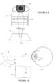
- FIGURE 1A illustrates an example system in accordance with at least some embodiments of the present invention. Illustrated is a user's eye 100, which comprises the pupil 110.
- the user uses a microscope 120, which is an example of an ocular device or in general a near-to-eye optical device.
- Microscope 120 comprises a plurality of optical components such as lenses, filters, beam splitters, light guides and/or mirrors, which are schematically illustrated using reference number 130.
- a sample is visible through the microscope on plate 140.
- Plate 140 may be of glass, for example, enabling illumination of the sample from below.
- Two possible gaze targets 150 are schematically illustrated on plate 140.
- Tracking the gaze of a user of a microscope gives valuable information concerning how the user observes the sample under study, for example what parts of the sample the user focuses on, for how long and what kind of gaze strategy the user uses.
- the pupil size may be estimated. This information may be used to estimate the user's awareness, workload and level of expertise, in educational purposes, and in assisting annotation of image areas. Gaze information may be used in controlling the functioning of an optical device, such as a microscope, for example. Thus manual controlling may be reduced.
- a pathologist or laboratory worker may also use his gaze point on a sample plate to guide the microscope to move the sample.
- a digital viewfinder may provide a visual indication when the user is looking at a target which may be a human.
- a sample may be automatically associated based on the gaze point identification with metadata indicating an extent to which it has been analysed, for example, whether a threshold has been reached. An example is a sample which must be analysed at least as to 70% of its contents.
- an eye-tracking camera which is not shown for the sake of clarity, is configured to image eye 100.
- the eye-tracking camera may image eye 100 from below, wherein the eye-tracking camera may be comprised in the ocular device being used, for example such that it may image the eye via a semipermeable mirror in the ocular device which is transparent to visible light but not the infra-red.
- the eye may be illuminated for this purpose by guide lights or light shaping or light generating devices, for example visible-light or infra-red, IR, lights, which may be generated using lightemitting diodes, LEDs, for example.
- IR lights An advantage of IR lights is that the human eye does not detect it, making the light unobtrusive to the user. IR light also allows for filtering out lighting and reflections of visible light sources the user is looking at or are visible in the environment, helping to control the lighting scheme.
- the corneal shape, illustrated in FIGURE 1B enables extracting information on the direction the eye is turned based on glints of the lights on the moist surface of the eye.
- the eye-tracking sensor such as, for example, a camera sensor, which is enabled to capture information of the user's eye may be based at least partly on charge-coupled device, CCD, technology, complementary metal-oxide semiconductor, CMOS, technology, and/or photosensitive photodiodes, for example, to produce a digital video or still data of the eye.
- charge-coupled device CCD, technology, complementary metal-oxide semiconductor, CMOS, technology, and/or photosensitive photodiodes, for example, to produce a digital video or still data of the eye.
- Such digital video or still data of the eye may include including reflections, glints, of the guide lights.
- a scene camera - not seen in the figure for the sake of clarity - is arranged to image plate 140.
- the scene camera may likewise be based on CCD technology, for example, to produce digital video or still data of the sample.
- the scene camera and the eye-tracking camera may be synchronized with each other to produce time-aligned images of eye 100 and plate 140.
- a transformation may be sought from a 3D coordinate system of an eye-tracking camera to a 3D coordinate system of a scene camera.
- the eye-tracking camera may be assisted by light-guides to generate glints, as described above, to enable determining a direction where the eye is turned toward.
- the presence of optical equipment 130 makes it more difficult to project a 3D gaze point into a scene camera's 2D coordinates.
- Some gaze tracking solutions are sensitive to movement of the user's head relative to the eye-tracking camera. In these cases, if the user moves after her calibration the gazetracking results will be inaccurate. Similarly, if the optical device in question moves during operation, it will result in a similar misalignment error.
- a typical usage session of an ocular device contains constant small head movements for adjusting the optimal viewing angle, or head movement due to the user leaving the operational position to view objects outside the ocular view and returning to it. The inaccuracy resulting from such head movement hinders gaze tracking.
- Methods disclosed herein enable robust gaze tracking despite the afore-mentioned unwanted head movements and entering and leaving an operational position.
- Much prior work in gaze tracking has used a two-dimensional, 2D, mapping from eye-tracking coordinates to scene camera coordinates which is less robust than a three-dimensional, 3D, algorithm.
- a 3D approach is complex to implement as such because the projection between the eye-tracking camera coordinate system, where a 3D gaze point may be computed in, and the 2D scene camera coordinate system is non-trivial to determine due to effects of the optical equipment 130.
- a two-phase gaze tracking method may be employed.
- data from the eye-tracking camera may be processed to determine a centre of the user's pupil and the centre of the user's cornea. These will be referred to herein as the pupil centre, Pc, and corneal centre, Cc. These may be determined as points in a three-dimensional space, enabling an optical vector L to be determined as a normalized vector traversing these points, establishing a direction of the gaze.
- different 3D features of the eye than the cornea and the pupil are used to compute a 3D optical point relating to the eye.
- a first eye feature and a second eye feature may be used to obtain the optical point.
- An example of an eye feature other than the cornea and the pupil is the iris, wherefore the first and second eye feature may comprise the iris and the pupil, for example.
- the gaze distance may be determined as follows: firstly, a virtual plane may be fitted to light-guide, such as IR LED locations. Secondly, the plane may then be shifted away from the user by a constant value, in the virtual plane's normal direction. The constant value is guessed or it is estimated during the user calibration. Thirdly, an intersection between the shifted plane and the (parameterized) vector Cc + d*L is computed, that is, d is found. Thus the gaze distance may be estimated per measurement and may be at least slightly different each time. Other ways of determining the gaze distance are also possible. The gaze distance is the distance from the eye to where the user's gaze is focused.
- FIGURE 4 illustrates an example of gaze distance estimation.
- a LED plane is fitted into LEDs by minimizing distances between the LEDs and the plane.
- the location of this plane is mathematically varied such that the plane is moved away from the eye by a distance D_fixed in a direction which is orthogonal to the LED plane when it is fitted to the LED elements. This results in the plane at the viewing plane location illustrated in FIGURE 4 .
- the distance D_fixed may be guessed, or it may be estimated during user calibration, or it may be known based on prior knowledge.
- the optical point, Op is defined as the intersection between the vector (Cc + dL) and the viewing plane. Illustrated are three possible optical vectors and the corresponding optical points Op1, Op2 and Op3.
- Calibration matrix K may be determined by conducting a calibration procedure with the user.
- the user fixates several target points with her gaze.
- the number of target points may be at least three or more than three.
- the target points should for ideal operation not be in a linear arrangement, for example they may form a grid of target points which avoids the linear arrangement of the target points being disposed on a straight line.
- a calibration sample is collected from the eye-tracking camera which constitutes an annotated target point, Gp_truth, and the optical point. These calibration samples taken together form a matrix equation from which the calibration matrix K can be solved.
- a calibration reference point in the three-dimensional space where the optical point will be determined corresponds to each of the target points. The larger the number of target points and samples, the better will be the expected accuracy of gaze tracking based on the calibration matrix. While a calibration matrix is discussed herein, more generally calibration information may be used.
- the procedure may be characterized as obtaining first and second eye features from a two-dimensional pixel scene of the eye-tracking camera.
- first and second eye features include the corneal centre and pupil centre.
- From locations of the first and second eye features in 3D space the reference point in a three-dimensional coordinate system is determined, and from the reference point the gaze point in a two-dimensional scene camera view is obtained.
- the coordinates of the gaze point may be determined, in the coordinate system of the scene camera, even in the event the gaze point is outside the view of the scene camera.
- the obtaining of the corneal centre and pupil centre from the output of the eye-tracking camera may be performed, for example, using the physical eye model described in Hennessey, Craig, Borna Noureddin, and Peter Lawrence. 2006. "A Single Camera Eye-Gaze Tracking System with Free Head Motion.” In Proceedings of the 2006 Symposium on Eye Tracking Research & Applications, 87-94. ACM .
- a neural network-based method may be used where the neural network is trained to output the optical vector when given an eye-tracking camera image as input.
- the reference point is determined based on the 3D characteristics of the eye, wherefore its location is to a degree invariant to small movements of the head. Further, alternatively or in addition, the gaze point may be determined also where it is disposed outside the view of the scene camera.
- FIGURE 1B illustrates coordinate mapping in accordance with at least some embodiments of the present invention.
- Eye 100 is disposed on the left, with pupil 110 and the corneal centre 160 marked thereon.
- the optical vector multiplied by the gaze distance, d*L, is denoted as element 161, pointing to the reference point 170.
- Reference point 170 is located in three-dimensional coordinate system, 165.
- a mapping 180 from coordinate system 165 to two-dimensional coordinate system 185 of the scene camera is denoted as mapping 180 in FIGURE 1B .
- the mapping associates reference point 170 to gaze point 190 in the coordinate system 185 of the scene camera.
- the ocular part(s) of a microscope may be supplemented with a module comprising the eye-tracking camera, suitable circuitry, and at least one light source for structured light, such as infrared light emitting elements.
- the microscope contains an ocular part for both eyes, both ocular parts may be provided with a similar module.
- the estimated gaze point may be determined as a weighted combination of separately determined left and right eye gaze points, weights being assigned score values of the estimation.
- the microscope may also contain a scene camera that views the sample and sees at least part of the view the user sees. A light path to the scene camera can be directed through a beam splitter which directs the same view to the user and to the scene camera, with different optical elements.
- the cameras may be connected into a computer using suitable interfaces, such as universal serial bus, USB, connectors, or integrated electrical leads.
- the computer may be furnished with a computer program which reads the camera streams and estimates the gaze point in the scene camera coordinates, as is depicted in FIGURE 1B .
- the computer program may be equipped with a graphical user interface which, for example, may be configured to show the scene camera view with a superimposed estimated gaze point.
- the computer program may also be configured to run the configuration process with the user to determine the calibration matrix K.
- the optical point may alternatively be determined by other means than with a physical eye model.
- machine learning approaches based on deep convolutional networks can be taught to automatically translate pupil and glint locations into gaze points and/or gaze directions.
- the ocular device used is a gun sight
- the two-dimensional output of the scene camera corresponds to plural gaze directions where the user is gazing.
- FIGURE 2 illustrates an example apparatus capable of supporting at least some embodiments of the present invention.
- device 200 which may comprise, for example, a gaze tracking module for an ocular device.
- processor 210 which may comprise, for example, a single- or multi-core processor wherein a single-core processor comprises one processing core and a multi-core processor comprises more than one processing core.
- Processor 210 may comprise, in general, a control device.
- Processor 210 may comprise more than one processor.
- Processor 210 may be a control device.
- a processing core may comprise, for example, a Cortex-A8 processing core manufactured by ARM Holdings or a Steamroller processing core designed by Advanced Micro Devices Corporation.
- Processor 210 may comprise at least one Qualcomm Snapdragon and/or Intel Atom processor.
- Processor 210 may comprise at least one application-specific integrated circuit, ASIC.
- Processor 210 may comprise at least one field-programmable gate array, FPGA.
- Processor 210 may be means for performing method steps in device 200, such as determining a reference point and performing a mapping.
- Processor 210 may be configured, at least in part by computer instructions, to perform actions.
- Device 200 may comprise memory 220.
- Memory 220 may comprise randomaccess memory and/or permanent memory.
- Memory 220 may comprise at least one RAM chip.
- Memory 220 may comprise solid-state, magnetic, optical and/or holographic memory, for example.
- Memory 220 may be at least in part accessible to processor 210.
- Memory 220 may be at least in part comprised in processor 210.
- Memory 220 may be means for storing information.
- Memory 220 may comprise computer instructions that processor 210 is configured to execute. When computer instructions configured to cause processor 210 to perform certain actions are stored in memory 220, and device 200 overall is configured to run under the direction of processor 210 using computer instructions from memory 220, processor 210 and/or its at least one processing core may be considered to be configured to perform said certain actions.
- Memory 220 may be at least in part comprised in processor 210.
- Memory 220 may be at least in part external to device 200 but accessible to device 200.
- Device 200 may comprise a transmitter 230.
- Device 200 may comprise a receiver 240.
- Transmitter 230 and receiver 240 may be configured to transmit and receive, respectively, information in accordance with at least one communication standard.
- Transmitter 230 may comprise more than one transmitter.
- Receiver 240 may comprise more than one receiver.
- Transmitter 230 and/or receiver 240 may be configured to operate in accordance with global system for mobile communication, GSM, wideband code division multiple access, WCDMA, 5G, long term evolution, LTE, IS-95, wireless local area network, WLAN, USB, Ethernet and/or worldwide interoperability for microwave access, WiMAX, standards, for example.
- Device 200 may comprise a near-field communication, NFC, transceiver 250.
- NFC transceiver 250 may support at least one NFC technology, such as NFC, Bluetooth, Wibree or similar technologies.
- Device 200 may comprise user interface, UI, 260.
- UI 260 may comprise at least one of a display, a keyboard, a touchscreen, a vibrator arranged to signal to a user by causing device 200 to vibrate, a speaker and a microphone.
- a user may be able to operate device 200 via UI 260, for example to perform a calibration process and/or gaze tracking operations.
- Processor 210 may be furnished with a transmitter arranged to output information from processor 210, via electrical leads internal to device 200, to other devices comprised in device 200.
- a transmitter may comprise a serial bus transmitter arranged to, for example, output information via at least one electrical lead to memory 220 for storage therein.
- the transmitter may comprise a parallel bus transmitter.
- processor 210 may comprise a receiver arranged to receive information in processor 210, via electrical leads internal to device 200, from other devices comprised in device 200.
- Such a receiver may comprise a serial bus receiver arranged to, for example, receive information via at least one electrical lead from receiver 240 for processing in processor 210.
- the receiver may comprise a parallel bus receiver.
- Device 200 may comprise further devices not illustrated in FIGURE 3 .
- Device 200 may comprise a fingerprint sensor arranged to authenticate, at least in part, a user of device 200.
- device 200 lacks at least one device described above.
- some devices 200 may lack the NFC transceiver 250 and/or at least one other unit described herein.
- Processor 210, memory 220, transmitter 230, receiver 240, NFC transceiver 250, and/or UI 260 may be interconnected by electrical leads internal to device 200 in a multitude of different ways.
- each of the aforementioned devices may be separately connected to a master bus internal to device 200, to allow for the devices to exchange information.
- this is only one example and depending on the embodiment various ways of interconnecting at least two of the aforementioned devices may be selected without departing from the scope of the present invention.
- FIGURE 3 is a flow graph of a method in accordance with at least some embodiments of the present invention.
- the phases of the illustrated method may be performed in device 200, an auxiliary device or a personal computer, for example, or in a control device configured to control the functioning thereof, when installed therein.
- phase 310 at least one eye image is obtained from the eye-tracking camera.
- phase 320 the pupil and glints of guide lights are located in the at least one eye image.
- phase 330 a 3D pupil centre, Pc, and 3D corneal centre, Cc, of the user are determined based on the pupil and glints, for example with the assistance of a model of the physical shape of the eye.
- phase 340 the optical vector L is determined, as described herein above.
- phase 350 the gaze distance is determined.
- the gaze point is the point on the plate 140 the user is looking at.
- At least some embodiments of the present invention find industrial application in tracking user gaze in ocular devices.
- Gaze point 100 Eye 110 Pupil 120 Microscope 130 Optical equipment 140 Plate 150 Gaze targets 160 Corneal centre 161 Vector d * L 165 Three-dimensional coordinate system 170 Optical point (reference point) 180 Mapping 185 Coordinate system of scene camera 190 Gaze point
Landscapes
- Engineering & Computer Science (AREA)
- Physics & Mathematics (AREA)
- Theoretical Computer Science (AREA)
- General Physics & Mathematics (AREA)
- General Engineering & Computer Science (AREA)
- Human Computer Interaction (AREA)
- Computer Vision & Pattern Recognition (AREA)
- Optics & Photonics (AREA)
- Computer Hardware Design (AREA)
- Multimedia (AREA)
- Analytical Chemistry (AREA)
- Chemical & Material Sciences (AREA)
- Health & Medical Sciences (AREA)
- General Health & Medical Sciences (AREA)
- Ophthalmology & Optometry (AREA)
- Eye Examination Apparatus (AREA)
- User Interface Of Digital Computer (AREA)
- Length Measuring Devices By Optical Means (AREA)
- Image Analysis (AREA)
- Position Input By Displaying (AREA)
Claims (10)
- Appareil (200) comprenant au moins un cœur de traitement (210), au moins une mémoire (220) incluant un code de programme informatique, la au moins une mémoire (220) et le code de programme informatique étant configurés pour, avec le au moins un cœur de traitement (210), amener l'appareil (200) au moins à :- déterminer (340) un point de référence dans un espace tridimensionnel sur la base au moins en partie d'emplacements de première et seconde caractéristiques de l'œil d'un utilisateur et de la distance de regard de l'utilisateur et- réaliser une cartographie (370) du point de référence dans une scène visualisée par un dispositif optique proche de l'œil pour obtenir un point de regard estimé et/ou une direction de regard estimée de l'utilisateur qui utilise le dispositif optique proche de l'œil, la cartographie étant basée au moins en partie sur des informations d'étalonnage associées à l'utilisateur, le dispositif optique proche de l'œil comprenant des guides de lumière,
caractérisé en ce que- le dispositif optique proche de l'œil comprend un dispositif oculaire et en ce que l'appareil est configuré pour obtenir la distance de regard (350) par l'ajustement d'un plan virtuel aux emplacements des guides de lumière en réduisant au minimum les distances entre les guides de lumière et le plan virtuel, le décalage du plan virtuel dans sa direction perpendiculaire d'une distance qui est générée de manière aléatoire ou sur la base de l'étalonnage d'utilisateur et la détermination d'une intersection du plan virtuel décalé et d'un vecteur qui traverse les première et seconde caractéristiques de l'œil de l'utilisateur. - Appareil (200) selon la revendication 1, dans lequel les première et seconde caractéristiques de l'œil de l'utilisateur sont un centre cornéen et un centre pupillaire.
- Appareil (200) selon la revendication 1 ou 2, dans lequel l'appareil est en outre configuré pour obtenir les informations d'étalonnage sous la forme d'une matrice d'étalonnage sur la base d'un processus d'étalonnage dans lequel l'utilisateur regarde trois points cibles ou plus en séquence, et un point de référence d'étalonnage distinct dans l'espace tridimensionnel est déterminé pour chaque point cible utilisé dans l'étalonnage.
- Appareil (200) selon l'une quelconque des revendications 1-3, dans lequel le dispositif optique proche de l'œil est un microscope, dans lequel l'appareil est configuré pour obtenir la direction de regard séparément pour chacun des deux yeux de l'utilisateur.
- Appareil (200) selon l'une quelconque des revendications 1-4, dans lequel l'appareil est compris dans le dispositif optique proche de l'œil.
- Procédé comprenant :- la détermination (340) d'un point de référence dans un espace tridimensionnel sur la base au moins en partie d'emplacements de première et seconde caractéristiques de l'œil d'un utilisateur et de la distance de regard de l'utilisateur et- la réalisation d'une cartographie (370) du point de référence dans une scène visualisée par un dispositif optique proche de l'œil pour obtenir un point de regard estimé et/ou une direction de regard estimée de l'utilisateur qui utilise le dispositif optique proche de l'œil, la cartographie étant basée au moins en partie sur des informations d'étalonnage associées à l'utilisateur, le dispositif optique proche de l'œil comprenant des guides de lumière,
caractérisé par- le fait que le dispositif optique proche de l'œil comprend un dispositif oculaire et par l'obtention de la distance de regard (350) par l'ajustement d'un plan virtuel à des emplacements des guides de lumière en réduisant au minimum les distances entre les guides de lumière et le plan virtuel, le décalage du plan virtuel dans sa direction perpendiculaire d'une distance qui est générée de manière aléatoire ou sur la base d'un étalonnage d'utilisateur, et la détermination d'une intersection du plan virtuel décalé et d'un vecteur qui traverse les première et seconde caractéristiques de l'œil de l'utilisateur. - Procédé selon la revendication 6, comprenant en outre l'obtention des informations d'étalonnage sous la forme d'une matrice d'étalonnage sur la base d'un processus d'étalonnage dans lequel l'utilisateur regarde trois points cibles ou plus en séquence, et un point de référence d'étalonnage distinct dans l'espace tridimensionnel est déterminé pour chaque point cible utilisé dans l'étalonnage.
- Procédé selon l'une quelconque des revendications 6-7, dans lequel le dispositif optique proche de l'œil est un microscope, dans lequel le procédé comprend en outre l'obtention de la direction de regard séparément pour chacun des deux yeux de l'utilisateur.
- Procédé selon l'une quelconque des revendications 6-8, comprenant en outre au moins l'une de la commande d'un microscope sur la base, au moins en partie, du point de regard estimé et/ou de la direction de regard estimée de l'utilisateur et de l'identification de l'utilisateur sur la base des informations d'étalonnage.
- Support non transitoire lisible par ordinateur présentant stocké sur celui-ci un ensemble d'instructions lisibles par ordinateur qui, lorsqu'elles sont exécutées par au moins un processeur (210), amènent un appareil (200) au moins à :- déterminer (340) un point de référence dans un espace tridimensionnel sur la base au moins en partie d'emplacements de première et seconde caractéristiques de l'œil d'un utilisateur et de la distance de regard de l'utilisateur et- réaliser une cartographie (370) du point de référence dans une scène visualisée par un dispositif optique proche de l'œil pour obtenir un point de regard estimé et/ou une direction de regard estimée de l'utilisateur utilisant le dispositif optique proche de l'œil, la cartographie étant basée au moins en partie sur des informations d'étalonnage associées à l'utilisateur, le dispositif optique proche de l'œil comprenant des guides de lumière,caractérisé par
le fait que le dispositif optique proche de l'œil comprend un dispositif oculaire et par le fait que l'ensemble d'instructions lisibles par ordinateur est configuré pour amener l'appareil à obtenir la distance de regard (350) par l'ajustement d'un plan virtuel à des emplacements des guides de lumière en réduisant au minimum les distances entre les guides de lumière et le plan virtuel, le décalage du plan virtuel dans sa direction perpendiculaire d'une distance qui est générée de manière aléatoire ou sur la base d'un étalonnage d'utilisateur et la détermination d'une intersection du plan virtuel décalé et d'un vecteur qui traverse les première et seconde caractéristiques de l'œil de l'utilisateur.
Applications Claiming Priority (2)
| Application Number | Priority Date | Filing Date | Title |
|---|---|---|---|
| FI20205182A FI130748B1 (en) | 2020-02-21 | 2020-02-21 | Gaze tracking |
| PCT/FI2021/050098 WO2021165570A1 (fr) | 2020-02-21 | 2021-02-12 | Suivi du regard |
Publications (3)
| Publication Number | Publication Date |
|---|---|
| EP4107603A1 EP4107603A1 (fr) | 2022-12-28 |
| EP4107603C0 EP4107603C0 (fr) | 2025-05-21 |
| EP4107603B1 true EP4107603B1 (fr) | 2025-05-21 |
Family
ID=74673253
Family Applications (1)
| Application Number | Title | Priority Date | Filing Date |
|---|---|---|---|
| EP21707314.7A Active EP4107603B1 (fr) | 2020-02-21 | 2021-02-12 | Suivi du regard |
Country Status (6)
| Country | Link |
|---|---|
| US (1) | US12086309B2 (fr) |
| EP (1) | EP4107603B1 (fr) |
| JP (1) | JP7472300B2 (fr) |
| KR (1) | KR102832232B1 (fr) |
| FI (1) | FI130748B1 (fr) |
| WO (1) | WO2021165570A1 (fr) |
Families Citing this family (1)
| Publication number | Priority date | Publication date | Assignee | Title |
|---|---|---|---|---|
| US12481355B2 (en) * | 2022-03-18 | 2025-11-25 | Htc Corporation | Method for determining two-eye gaze point and host |
Family Cites Families (14)
| Publication number | Priority date | Publication date | Assignee | Title |
|---|---|---|---|---|
| DE59504515D1 (de) | 1994-10-26 | 1999-01-21 | Leica Mikroskopie Sys Ag | Mikroskop, insbesondere operationsmikroskop |
| JP2006075348A (ja) * | 2004-09-09 | 2006-03-23 | Fuji Xerox Co Ltd | 相互視分析装置、相互視分析方法および相互視分析プログラム |
| US8885882B1 (en) | 2011-07-14 | 2014-11-11 | The Research Foundation For The State University Of New York | Real time eye tracking for human computer interaction |
| CA2750287C (fr) | 2011-08-29 | 2012-07-03 | Microsoft Corporation | Detection du regard dans un affichage transparent, pres de l'oeil et de realite mixte |
| WO2015034560A1 (fr) | 2013-09-03 | 2015-03-12 | Tobii Technology Ab | Dispositif de suivi oculaire portable |
| CN103558909B (zh) * | 2013-10-10 | 2017-03-29 | 北京智谷睿拓技术服务有限公司 | 交互投射显示方法及交互投射显示系统 |
| WO2015154882A1 (fr) | 2014-04-11 | 2015-10-15 | The Eye Tribe Aps | Systèmes et procédés d'étalonnage de suivi oculaire |
| JP6631951B2 (ja) | 2015-12-18 | 2020-01-15 | 国立大学法人静岡大学 | 視線検出装置及び視線検出方法 |
| EP3475785A4 (fr) | 2016-04-22 | 2020-05-13 | SZ DJI Technology Co., Ltd. | Systèmes et procédés de traitement de données d'image en fonction d'une région d'intérêt (roi) d'un utilisateur |
| US10572009B2 (en) * | 2017-05-22 | 2020-02-25 | Htc Corporation | Eye tracking method, electronic device, and non-transitory computer readable storage medium |
| US10698204B1 (en) * | 2017-10-16 | 2020-06-30 | Facebook Technologies, Llc | Immersed hot mirrors for illumination in eye tracking |
| WO2019190561A1 (fr) * | 2018-03-30 | 2019-10-03 | Tobii Ab | Apprentissage profond pour prédiction tridimensionnelle (3d) de regard |
| CN110441901A (zh) * | 2019-08-14 | 2019-11-12 | 东北大学 | 一种可实时追踪注视位置的光学显微镜系统及方法 |
| US11506888B2 (en) * | 2019-09-20 | 2022-11-22 | Nvidia Corp. | Driver gaze tracking system for use in vehicles |
-
2020
- 2020-02-21 FI FI20205182A patent/FI130748B1/en active
-
2021
- 2021-02-12 WO PCT/FI2021/050098 patent/WO2021165570A1/fr not_active Ceased
- 2021-02-12 US US17/801,277 patent/US12086309B2/en active Active
- 2021-02-12 JP JP2022550670A patent/JP7472300B2/ja active Active
- 2021-02-12 EP EP21707314.7A patent/EP4107603B1/fr active Active
- 2021-02-12 KR KR1020227032591A patent/KR102832232B1/ko active Active
Also Published As
| Publication number | Publication date |
|---|---|
| KR102832232B1 (ko) | 2025-07-10 |
| FI20205182A1 (en) | 2021-08-22 |
| EP4107603A1 (fr) | 2022-12-28 |
| WO2021165570A1 (fr) | 2021-08-26 |
| US12086309B2 (en) | 2024-09-10 |
| JP7472300B2 (ja) | 2024-04-22 |
| KR20220133314A (ko) | 2022-10-04 |
| US20230104656A1 (en) | 2023-04-06 |
| EP4107603C0 (fr) | 2025-05-21 |
| JP2023514419A (ja) | 2023-04-05 |
| FI130748B1 (en) | 2024-02-26 |
Similar Documents
| Publication | Publication Date | Title |
|---|---|---|
| Lee et al. | 3D gaze tracking method using Purkinje images on eye optical model and pupil | |
| US10165176B2 (en) | Methods, systems, and computer readable media for leveraging user gaze in user monitoring subregion selection systems | |
| CN104834381B (zh) | 用于视线焦点定位的可穿戴设备及视线焦点定位方法 | |
| US9513478B2 (en) | Mirror system and control method therefor | |
| US10578851B2 (en) | Automated hardware and software for mobile microscopy | |
| WO2015013022A1 (fr) | Procédé et calculs pour calculer un vecteur d'axe optique d'un œil imagé | |
| WO2018076202A1 (fr) | Dispositif d'affichage monté sur la tête pouvant effectuer un suivi de l'œil, et procédé de suivi de l'œil | |
| EP4325450B1 (fr) | Procédé et système d'analyse de mouvement oculaire | |
| KR20120127790A (ko) | 시선추적 시스템 및 그 방법 | |
| US20150009103A1 (en) | Wearable Display, Computer-Readable Medium Storing Program and Method for Receiving Gesture Input | |
| EP4285204B1 (fr) | Éclairage de suivi de l'oeil | |
| CN104749777A (zh) | 可穿戴智能设备的互动方法 | |
| JP2019215688A (ja) | 自動キャリブレーションを行う視線計測装置、視線計測方法および視線計測プログラム | |
| Kim et al. | Head-mounted binocular gaze detection for selective visual recognition systems | |
| EP4107603B1 (fr) | Suivi du regard | |
| Perra et al. | Adaptive eye-camera calibration for head-worn devices | |
| KR101739768B1 (ko) | 스테레오 카메라와 협각 카메라를 이용한 원거리 시선 추적 시스템 | |
| RU2007117996A (ru) | Способ измерения быстрых движений глаз и отклонений бинокулярного зрения и устройство для его реализации | |
| CN114155280A (zh) | 一种双目视线追踪方法、装置及设备 | |
| EP3975114A1 (fr) | Dispositif de détection de globe oculaire, dispositif de détection de ligne de visée, procédé de détection de globe oculaire et programme de détection de globe oculaire | |
| CN113080841A (zh) | 用于检测眼球运动精准度的方法 | |
| US20230252671A1 (en) | Gaze Tracking | |
| Changyuan et al. | The line of sight to estimate method based on stereo vision | |
| KR20200098150A (ko) | 시선추적 데이터 처리 방법 | |
| Nishiuchi et al. | A man-machine interface for camera control in remote monitoring using line-of-sight |
Legal Events
| Date | Code | Title | Description |
|---|---|---|---|
| STAA | Information on the status of an ep patent application or granted ep patent |
Free format text: STATUS: UNKNOWN |
|
| STAA | Information on the status of an ep patent application or granted ep patent |
Free format text: STATUS: THE INTERNATIONAL PUBLICATION HAS BEEN MADE |
|
| PUAI | Public reference made under article 153(3) epc to a published international application that has entered the european phase |
Free format text: ORIGINAL CODE: 0009012 |
|
| STAA | Information on the status of an ep patent application or granted ep patent |
Free format text: STATUS: REQUEST FOR EXAMINATION WAS MADE |
|
| 17P | Request for examination filed |
Effective date: 20220819 |
|
| AK | Designated contracting states |
Kind code of ref document: A1 Designated state(s): AL AT BE BG CH CY CZ DE DK EE ES FI FR GB GR HR HU IE IS IT LI LT LU LV MC MK MT NL NO PL PT RO RS SE SI SK SM TR |
|
| DAV | Request for validation of the european patent (deleted) | ||
| DAX | Request for extension of the european patent (deleted) | ||
| GRAP | Despatch of communication of intention to grant a patent |
Free format text: ORIGINAL CODE: EPIDOSNIGR1 |
|
| STAA | Information on the status of an ep patent application or granted ep patent |
Free format text: STATUS: GRANT OF PATENT IS INTENDED |
|
| INTG | Intention to grant announced |
Effective date: 20250128 |
|
| GRAS | Grant fee paid |
Free format text: ORIGINAL CODE: EPIDOSNIGR3 |
|
| GRAA | (expected) grant |
Free format text: ORIGINAL CODE: 0009210 |
|
| STAA | Information on the status of an ep patent application or granted ep patent |
Free format text: STATUS: THE PATENT HAS BEEN GRANTED |
|
| AK | Designated contracting states |
Kind code of ref document: B1 Designated state(s): AL AT BE BG CH CY CZ DE DK EE ES FI FR GB GR HR HU IE IS IT LI LT LU LV MC MK MT NL NO PL PT RO RS SE SI SK SM TR |
|
| REG | Reference to a national code |
Ref country code: GB Ref legal event code: FG4D |
|
| REG | Reference to a national code |
Ref country code: CH Ref legal event code: EP |
|
| RAP4 | Party data changed (patent owner data changed or rights of a patent transferred) |
Owner name: SEETRUE TECHNOLOGIES OY |
|
| REG | Reference to a national code |
Ref country code: DE Ref legal event code: R096 Ref document number: 602021031085 Country of ref document: DE |
|
| REG | Reference to a national code |
Ref country code: IE Ref legal event code: FG4D |
|
| U01 | Request for unitary effect filed |
Effective date: 20250602 |
|
| U07 | Unitary effect registered |
Designated state(s): AT BE BG DE DK EE FI FR IT LT LU LV MT NL PT RO SE SI Effective date: 20250606 |
|
| PG25 | Lapsed in a contracting state [announced via postgrant information from national office to epo] |
Ref country code: ES Free format text: LAPSE BECAUSE OF FAILURE TO SUBMIT A TRANSLATION OF THE DESCRIPTION OR TO PAY THE FEE WITHIN THE PRESCRIBED TIME-LIMIT Effective date: 20250521 |
|
| PG25 | Lapsed in a contracting state [announced via postgrant information from national office to epo] |
Ref country code: GR Free format text: LAPSE BECAUSE OF FAILURE TO SUBMIT A TRANSLATION OF THE DESCRIPTION OR TO PAY THE FEE WITHIN THE PRESCRIBED TIME-LIMIT Effective date: 20250822 Ref country code: NO Free format text: LAPSE BECAUSE OF FAILURE TO SUBMIT A TRANSLATION OF THE DESCRIPTION OR TO PAY THE FEE WITHIN THE PRESCRIBED TIME-LIMIT Effective date: 20250821 |
|
| PG25 | Lapsed in a contracting state [announced via postgrant information from national office to epo] |
Ref country code: PL Free format text: LAPSE BECAUSE OF FAILURE TO SUBMIT A TRANSLATION OF THE DESCRIPTION OR TO PAY THE FEE WITHIN THE PRESCRIBED TIME-LIMIT Effective date: 20250521 |
|
| PG25 | Lapsed in a contracting state [announced via postgrant information from national office to epo] |
Ref country code: HR Free format text: LAPSE BECAUSE OF FAILURE TO SUBMIT A TRANSLATION OF THE DESCRIPTION OR TO PAY THE FEE WITHIN THE PRESCRIBED TIME-LIMIT Effective date: 20250521 |
|
| PG25 | Lapsed in a contracting state [announced via postgrant information from national office to epo] |
Ref country code: RS Free format text: LAPSE BECAUSE OF FAILURE TO SUBMIT A TRANSLATION OF THE DESCRIPTION OR TO PAY THE FEE WITHIN THE PRESCRIBED TIME-LIMIT Effective date: 20250821 |
|
| PG25 | Lapsed in a contracting state [announced via postgrant information from national office to epo] |
Ref country code: IS Free format text: LAPSE BECAUSE OF FAILURE TO SUBMIT A TRANSLATION OF THE DESCRIPTION OR TO PAY THE FEE WITHIN THE PRESCRIBED TIME-LIMIT Effective date: 20250921 |
|
| PG25 | Lapsed in a contracting state [announced via postgrant information from national office to epo] |
Ref country code: SM Free format text: LAPSE BECAUSE OF FAILURE TO SUBMIT A TRANSLATION OF THE DESCRIPTION OR TO PAY THE FEE WITHIN THE PRESCRIBED TIME-LIMIT Effective date: 20250521 |
|
| PG25 | Lapsed in a contracting state [announced via postgrant information from national office to epo] |
Ref country code: CZ Free format text: LAPSE BECAUSE OF FAILURE TO SUBMIT A TRANSLATION OF THE DESCRIPTION OR TO PAY THE FEE WITHIN THE PRESCRIBED TIME-LIMIT Effective date: 20250521 |
|
| PG25 | Lapsed in a contracting state [announced via postgrant information from national office to epo] |
Ref country code: SK Free format text: LAPSE BECAUSE OF FAILURE TO SUBMIT A TRANSLATION OF THE DESCRIPTION OR TO PAY THE FEE WITHIN THE PRESCRIBED TIME-LIMIT Effective date: 20250521 |
|
| REG | Reference to a national code |
Ref country code: CH Ref legal event code: U11 Free format text: ST27 STATUS EVENT CODE: U-0-0-U10-U11 (AS PROVIDED BY THE NATIONAL OFFICE) Effective date: 20260301 |
|
| U20 | Renewal fee for the european patent with unitary effect paid |
Year of fee payment: 6 Effective date: 20260205 |
|
| PLBE | No opposition filed within time limit |
Free format text: ORIGINAL CODE: 0009261 |
|
| STAA | Information on the status of an ep patent application or granted ep patent |
Free format text: STATUS: NO OPPOSITION FILED WITHIN TIME LIMIT |
|
| REG | Reference to a national code |
Ref country code: CH Ref legal event code: L10 Free format text: ST27 STATUS EVENT CODE: U-0-0-L10-L00 (AS PROVIDED BY THE NATIONAL OFFICE) Effective date: 20260402 |
|
| PGFP | Annual fee paid to national office [announced via postgrant information from national office to epo] |
Ref country code: GB Payment date: 20260220 Year of fee payment: 6 |
|
| PGFP | Annual fee paid to national office [announced via postgrant information from national office to epo] |
Ref country code: CH Payment date: 20260301 Year of fee payment: 6 |
|
| 26N | No opposition filed |
Effective date: 20260224 |