EP4108060A1 - Dispositif d'ancrage de lignes de coupe sur une tête inter-rangées et tête inter-rangées dotée d'un tel dispositif - Google Patents
Dispositif d'ancrage de lignes de coupe sur une tête inter-rangées et tête inter-rangées dotée d'un tel dispositif Download PDFInfo
- Publication number
- EP4108060A1 EP4108060A1 EP22153176.7A EP22153176A EP4108060A1 EP 4108060 A1 EP4108060 A1 EP 4108060A1 EP 22153176 A EP22153176 A EP 22153176A EP 4108060 A1 EP4108060 A1 EP 4108060A1
- Authority
- EP
- European Patent Office
- Prior art keywords
- line guiding
- disk
- pivot
- hole
- bushing
- Prior art date
- Legal status (The legal status is an assumption and is not a legal conclusion. Google has not performed a legal analysis and makes no representation as to the accuracy of the status listed.)
- Pending
Links
Images


Classifications
-
- A—HUMAN NECESSITIES
- A01—AGRICULTURE; FORESTRY; ANIMAL HUSBANDRY; HUNTING; TRAPPING; FISHING
- A01D—HARVESTING; MOWING
- A01D34/00—Mowers; Mowing apparatus of harvesters
- A01D34/01—Mowers; Mowing apparatus of harvesters characterised by features relating to the type of cutting apparatus
- A01D34/412—Mowers; Mowing apparatus of harvesters characterised by features relating to the type of cutting apparatus having rotating cutters
- A01D34/416—Flexible line cutters
- A01D34/4166—Mounting or replacement of the lines
Definitions
- the present invention relates to a device for anchoring trimming lines to an inter-row head.
- the invention also relates to an inter-row head with such a device.
- the inter-row head is an apparatus which can be applied to various grass trimming machines, such as for example a shredder, mainly on orchards, vineyards or crops in which it is important to keep the stems of plants free from weeds.
- grass trimming machines such as for example a shredder, mainly on orchards, vineyards or crops in which it is important to keep the stems of plants free from weeds.
- the inter-row head comprises a support/cover having a circular contour below which, in the configuration for use, there is a substantially disk-like rotor, which rotates about its own axis, is concentric to the support/cover, and from which trimming lines, generally made of nylon, having such a length and profile as not to protrude radially from the space occupation of the support/cover, extend radially.
- Such rotor is moved by a motor.
- the motor turns the rotor, which due to its rotation moves the trimming lines, which cut the grass by striking it.
- Trimming lines are normally fixed mechanically to the rotor by virtue of anchoring elements, for example fastening means such as clamps and/or clips, or knots on adapted eyelets.
- fastening means entails a line fixing and/or replacement process that is long and not always easy.
- the aim of the present invention is to provide a device for anchoring lines to an inter-row head that is capable of improving the background art in one or more of the aspects indicated above.
- an object of the invention is to provide a device for anchoring trimming lines to an inter-row head that allows to reduce the stresses on the lines with respect to the anchoring means of the known type, at the same time limiting the friction of the lines against said means and increasing their strength and lifespan.
- Another object of the invention is to provide a device for anchoring trimming lines to an inter-row head that makes it possible to lower and easier maintenance/replacement of the lines with respect to anchoring means of the known type.
- Another object of the invention is to provide an inter-row head provided with a device for anchoring trimming lines that is capable of achieving the aim and objects described above.
- An object of the present invention is furthermore to overcome the drawbacks of the background art in a manner that is alternative to any existing solutions.
- Another object of the invention is to provide a device for anchoring trimming lines to an inter-row head that is highly reliable, relatively easy to provide and at competitive costs.
- a device for anchoring trimming lines to an inter-row head provided with a rotor comprising a flat body for coupling to said inter-row head, said device being characterized in that it comprises at least one line guiding element which is free with respect to said body.
- an inter-row head which comprises a motor and a rotor, moved by said motor, characterized in that it comprises such a device.
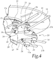
- a device for anchoring trimming lines to an inter-row head in a first embodiment, is designated generally by the reference numeral 10.
- the device 10 for anchoring trimming lines 14 is applied to an inter-row head 11, which comprises a rotor 12 driven by a motor 13.
- the device 10 comprises a flat body 15 for coupling to the inter-row head 11, which is associated with the rotor 12 and is concentric thereto in the configuration for use.
- the body 15 has a cross-like contour; however, in other embodiments the body 15 can have other contours, for example a circular or quadrangular one.
- the device 10 comprises at least:
- the term "free" means that the line guiding elements 17a, 17b can rotate freely about their own axis, which is perpendicular to the plane of arrangement of the body 15.
- the device 10 comprises, for each trimming line 14, a first line guiding element 16 and two second line guiding elements 17a, 17b.
- the first line guiding element 16 is, for example, monolithic with the body 15 and/or welded and/or fixed permanently to a surface 25 that is a lower surface in the configuration for use, of the body 15.
- Such first line guiding element 16 has a first through hole 24, with an axis of extension that is parallel to the plane of arrangement of the body 15.
- Each second line guiding element 17a, 17b instead comprises a bolt which comprises a pivot/screw 18 with a perforated head 19, which is directed toward the surface 25 that is a lower surfacein the configuration for use, of the body 15.
- the pivot 18 is inserted in a corresponding through hole of said body 15 which has a bushing 20 for preventing seizing and is fastened onto the upper surface of the latter by means of a locking nut 22.
- the bushing 20, made of carburized steel, suitable for the insertion of the pivot 18, is inserted by pressing into a corresponding through hole of the body 15.
- Each second line guiding element 17a, 17b comprises, in the following order, between the upper surface 26 of the body 15 and the locking nut 22:
- the pivot 18 has, on the head 19, a second through hole 23 with an axis of extension that is parallel to the plane of arrangement of the body 15 and a stem which is extended at right angles to the head 19 and has, starting from the latter:
- the first portion 27, which is free, can therefore rotate about the axis of extension of the stem of the pivot 18, within the corresponding hole of the body 15 and/or of the bushing 20 in which the latter is inserted.
- the first line guiding element 16 and the second line guiding elements 17a, 17b are crossed by a trimming line 14, in the configuration for use, with the first line guiding element 16 interposed between the two second line guiding elements 17a, 17b, along the trajectory of extension of the trimming line 14.
- the second line guiding elements 17a, 17b are arranged in a mirror-symmetrical manner with respect to the first line guiding element 16, so as to give the trimming line 14, which passes through them, a U-like shape, with the wings of the U which are substantially radial with respect to the axis of rotation of the body 15.
- the body 15 has a cross-like contour with four wings 29, each of which extends from a central tubular element 30, and is concentric to the rotor 12 of the inter-row head 11.
- Each one of the wings 29 is provided with a trimming line 14 and comprises a first line guiding element 16 and two second line guiding elements 17a, 17b.
- the two second line guiding elements 17a, 17b are substantially proximate to the free end of the respective wing 29.
- the motor 13 moves the rotor 12 on which the body 15 is keyed and which, by rotating, entrains with it the trimming lines 14, moving them.
- the two second line guiding elements 17a, 17b being free with respect to the body 15, can rotate about their own axis, assisting at least partially the trajectory of the lines 14 during cutting.
- the first line guiding element 16 is adapted to guide the line 14 without allowing to extract it from the device.
- the anchoring of the trimming lines 14 to the inter-row head 11 is reversible.
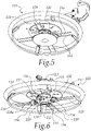
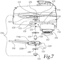
- Figures 5 to 7 show a device for anchoring trimming lines to an inter-row head according to the invention in a second embodiment, generally designated by the reference numeral 110.
- the device 110 for anchoring trimming lines 114 is applied to an inter-row head 111, which comprises a rotor 112 driven by a motor 113.
- the device 110 comprises a flat body 115, for coupling to the inter-row head 111, which is associated with the rotor 112 and is concentric thereto in the configuration for use.
- the body 115 has a cross-like contour, but in other embodiments the body 115 may have other outlines, for example a circular or quadrangular one.
- the device 110 comprises at least one line guiding element 116 which is free with respect to the body 115.
- the term "free” is understood to mean that the line guiding element 116 can at least partially rotate freely about its own axis, which is perpendicular to the plane of arrangement of the body 115.
- the device 110 comprises a line guiding element 116 for each line 114.
- the line guiding element 116 comprises a disk-like element 117 which has a plane of arrangement that is parallel to the plane of arrangement of the body 115 and has two opposite and mirror-symmetrical through openings 118a, 118b, with an axis of extension that is parallel to the plane of arrangement of the disk-like element 117, in which the line 114 is inserted.
- the disk-like element 117 has a perimetric/circumferential slot 119, which has an arc-like profile, for the accommodation of a corresponding portion of the line 114.
- the line 114 has a U-shaped extension around the axis of rotation of the disk-like element 117, with the wings of the U-shape substantially radial with respect to the axis of rotation of the body 115.
- the disk-like element 117 is made of plastic or metallic material.
- the disk-like element 117 is provided with a first through hole 120, with an axis of extension that is perpendicular to the plane of arrangement of the body 115 and coincides with the rotation axis of the disk-like element 117.
- the line guiding element 116 comprises a bolt which in turn comprises:
- the pivot/screw 121 is inserted in a corresponding second through hole 125 of the body 115 and in the first through hole 120 of the disk-like element 117, fastening the disk-like element 117 to the body 115 by means of the nut 124.
- the line guiding element 116 comprises a tubular bushing 126, which is inserted in the first through hole 120 of the disk-like element 117.
- the bushing 126 has an inside diameter that is larger than the diameter of the stem 127 of the pivot/screw 121.
- the line guiding element 116 comprises a plurality of washers which are crossed by the stem 127 of the pivot/screw 121, in the following order:
- pivot/screw 121 passes in the following order through:
- the components of the line guiding element 116 have shapes and dimensions such that the pivot/screw 121 is fixed with respect to the second hole 125 of the body 115 and the disk-like element 117 is free with respect to the bushing 126 and/or the body 115.
- the bushing 126 is higher than the height of the disk-like element 117.
- the term "height” is understood to refer to the dimension along an axis that is perpendicular to the plane of arrangement of the body 115.
- the first through hole 120 of the disk-like element 117 has a diameter that is larger than the outside diameter of the bushing 126 and such as to allow the disk-like element 117 to be free with respect to the bushing 126 and to rotate about the latter.
- the bushing 126 with the disk-like element 117 around it, is therefore associated with the body 115 by means of: the pivot/screw 121, the first washer 128, the second washer 129, the third washer 130, and the nut 124.
- the body 115 has a cross-like contour with four wings 132, each of which extends from a central tubular element 133 which is concentric to the rotor 112 of the inter-row head 111.
- Each one of the wings 132 is provided with a trimming line 114 and comprises a line guiding element 116.
- the motor 113 moves the rotor 112 on which the body 115 is keyed, and which, by rotating, entrains with it the trimming lines 114, moving them.
- the line guiding elements 116 being free with respect to the body 115, can rotate about their own axis, at least partially following the trajectory of the lines 114 during trimming.
- the slot 119 of the disk-like element 117, of the line guiding element 116, is adapted to guide the line 114 without allowing it to be extracted from the device.
- the invention achieves the intended aim and objects, providing a device for anchoring trimming lines to an inter-row head that allows to reduce the stresses on the lines with respect to anchoring means of the known type, at the same time limiting the friction of the lines thereon and increasing strength and lifespan.
- the invention provides a device for anchoring lines to an inter-row head that allows a reduced and easier maintenance/replacement of the lines with respect to anchoring means of the known type.
- the materials used may be any according to the requirements and the state of the art.
Landscapes
- Life Sciences & Earth Sciences (AREA)
- Environmental Sciences (AREA)
- Connection Of Plates (AREA)
Applications Claiming Priority (2)
| Application Number | Priority Date | Filing Date | Title |
|---|---|---|---|
| IT102021000003443A IT202100003443A1 (it) | 2021-02-16 | 2021-02-16 | Dispositivo perfezionato per l'ancoraggio dei fili di taglio su testata interfilare e testata interfilare con un simile dispositivo |
| IT202100011570 | 2021-05-06 |
Publications (1)
| Publication Number | Publication Date |
|---|---|
| EP4108060A1 true EP4108060A1 (fr) | 2022-12-28 |
Family
ID=79687152
Family Applications (1)
| Application Number | Title | Priority Date | Filing Date |
|---|---|---|---|
| EP22153176.7A Pending EP4108060A1 (fr) | 2021-02-16 | 2022-01-25 | Dispositif d'ancrage de lignes de coupe sur une tête inter-rangées et tête inter-rangées dotée d'un tel dispositif |
Country Status (1)
| Country | Link |
|---|---|
| EP (1) | EP4108060A1 (fr) |
Citations (5)
| Publication number | Priority date | Publication date | Assignee | Title |
|---|---|---|---|---|
| JPH0837872A (ja) * | 1994-07-28 | 1996-02-13 | Maruyama Mfg Co Ltd | 紐刃式刈払機の紐刃ヘッド |
| JPH10234216A (ja) * | 1997-02-25 | 1998-09-08 | Kiyoueishiya:Kk | 草刈用カッター |
| US5970693A (en) * | 1998-08-31 | 1999-10-26 | Ciaglo; Walter M. | Filament employing lawnmower blade apparatus |
| US6666009B1 (en) * | 2001-02-28 | 2003-12-23 | Dennis Brandon | Adjustable spindle assembly for a grass trimmer |
| EP3536140A1 (fr) * | 2018-03-09 | 2019-09-11 | TTI (Macao Commercial Offshore) Limited | Fixation de tondeuse à fil pour une tête de tondeuse |
-
2022
- 2022-01-25 EP EP22153176.7A patent/EP4108060A1/fr active Pending
Patent Citations (5)
| Publication number | Priority date | Publication date | Assignee | Title |
|---|---|---|---|---|
| JPH0837872A (ja) * | 1994-07-28 | 1996-02-13 | Maruyama Mfg Co Ltd | 紐刃式刈払機の紐刃ヘッド |
| JPH10234216A (ja) * | 1997-02-25 | 1998-09-08 | Kiyoueishiya:Kk | 草刈用カッター |
| US5970693A (en) * | 1998-08-31 | 1999-10-26 | Ciaglo; Walter M. | Filament employing lawnmower blade apparatus |
| US6666009B1 (en) * | 2001-02-28 | 2003-12-23 | Dennis Brandon | Adjustable spindle assembly for a grass trimmer |
| EP3536140A1 (fr) * | 2018-03-09 | 2019-09-11 | TTI (Macao Commercial Offshore) Limited | Fixation de tondeuse à fil pour une tête de tondeuse |
Similar Documents
| Publication | Publication Date | Title |
|---|---|---|
| US5887348A (en) | Head for string trimmer | |
| US7257898B2 (en) | Cutting head for string trimmer | |
| US4268964A (en) | Apparatus for cutting, trimming and edging vegetation and the like | |
| US4086700A (en) | Cutting head for a mower | |
| US4043037A (en) | Cord-type mowing tool | |
| CA1102559A (fr) | Traduction non-disponible | |
| US6052974A (en) | Adjustable height head for string trimmer | |
| US4316685A (en) | Plunge type router | |
| US3222854A (en) | Swing-knife mounting | |
| EP4108060A1 (fr) | Dispositif d'ancrage de lignes de coupe sur une tête inter-rangées et tête inter-rangées dotée d'un tel dispositif | |
| EP1585380B1 (fr) | Tete de coupe pour debroussailleuse, taille-haies ou analogue | |
| US3555680A (en) | Trim around sprinkler head tool | |
| US4058959A (en) | Grass cutting blades | |
| US8291599B2 (en) | Universal mowing head for flexible cutter | |
| EP2974586A1 (fr) | Tête de coupe pour débroussailleuses | |
| DE102005035024A1 (de) | Schutzschild für einen Freischneider | |
| US4223440A (en) | Cord-type mowing machine | |
| US4316325A (en) | Weed cutting apparatus | |
| KR102524444B1 (ko) | 예초기용 강선 와이어 커터의 고정구조 | |
| US2677309A (en) | Valve seat dressing tool | |
| US6038774A (en) | Sprinkler head trimmer | |
| KR102325080B1 (ko) | 스프링클러 헤드부 주변 정리기 | |
| AU749074B2 (en) | Head for string trimmer | |
| KR101757869B1 (ko) | 커터날 이탈방지 및 하우징 파손 방지 기능을 갖는 예초기 안전날 유닛 | |
| US2280295A (en) | Bit |
Legal Events
| Date | Code | Title | Description |
|---|---|---|---|
| PUAI | Public reference made under article 153(3) epc to a published international application that has entered the european phase |
Free format text: ORIGINAL CODE: 0009012 |
|
| STAA | Information on the status of an ep patent application or granted ep patent |
Free format text: STATUS: THE APPLICATION HAS BEEN PUBLISHED |
|
| AK | Designated contracting states |
Kind code of ref document: A1 Designated state(s): AL AT BE BG CH CY CZ DE DK EE ES FI FR GB GR HR HU IE IS IT LI LT LU LV MC MK MT NL NO PL PT RO RS SE SI SK SM TR |
|
| STAA | Information on the status of an ep patent application or granted ep patent |
Free format text: STATUS: REQUEST FOR EXAMINATION WAS MADE |
|
| 17P | Request for examination filed |
Effective date: 20230608 |
|
| P01 | Opt-out of the competence of the unified patent court (upc) registered |
Effective date: 20230527 |
|
| RBV | Designated contracting states (corrected) |
Designated state(s): AL AT BE BG CH CY CZ DE DK EE ES FI FR GB GR HR HU IE IS IT LI LT LU LV MC MK MT NL NO PL PT RO RS SE SI SK SM TR |
|
| STAA | Information on the status of an ep patent application or granted ep patent |
Free format text: STATUS: EXAMINATION IS IN PROGRESS |
|
| 17Q | First examination report despatched |
Effective date: 20250822 |
|
| STAA | Information on the status of an ep patent application or granted ep patent |
Free format text: STATUS: THE APPLICATION IS DEEMED TO BE WITHDRAWN |