EP4108069A1 - Presse à balles rondes - Google Patents
Presse à balles rondes Download PDFInfo
- Publication number
- EP4108069A1 EP4108069A1 EP22178744.3A EP22178744A EP4108069A1 EP 4108069 A1 EP4108069 A1 EP 4108069A1 EP 22178744 A EP22178744 A EP 22178744A EP 4108069 A1 EP4108069 A1 EP 4108069A1
- Authority
- EP
- European Patent Office
- Prior art keywords
- rocker
- tailgate
- pressure element
- round baler
- pressing
- Prior art date
- Legal status (The legal status is an assumption and is not a legal conclusion. Google has not performed a legal analysis and makes no representation as to the accuracy of the status listed.)
- Granted
Links
Images


Classifications
-
- A—HUMAN NECESSITIES
- A01—AGRICULTURE; FORESTRY; ANIMAL HUSBANDRY; HUNTING; TRAPPING; FISHING
- A01F—PROCESSING OF HARVESTED PRODUCE; HAY OR STRAW PRESSES; DEVICES FOR STORING AGRICULTURAL OR HORTICULTURAL PRODUCE
- A01F15/00—Baling presses for straw, hay or the like
- A01F15/08—Details
- A01F15/0875—Discharge devices
- A01F15/0883—Discharge devices for round balers
-
- A—HUMAN NECESSITIES
- A01—AGRICULTURE; FORESTRY; ANIMAL HUSBANDRY; HUNTING; TRAPPING; FISHING
- A01F—PROCESSING OF HARVESTED PRODUCE; HAY OR STRAW PRESSES; DEVICES FOR STORING AGRICULTURAL OR HORTICULTURAL PRODUCE
- A01F15/00—Baling presses for straw, hay or the like
- A01F15/07—Rotobalers, i.e. machines for forming cylindrical bales by winding and pressing
-
- A—HUMAN NECESSITIES
- A01—AGRICULTURE; FORESTRY; ANIMAL HUSBANDRY; HUNTING; TRAPPING; FISHING
- A01F—PROCESSING OF HARVESTED PRODUCE; HAY OR STRAW PRESSES; DEVICES FOR STORING AGRICULTURAL OR HORTICULTURAL PRODUCE
- A01F15/00—Baling presses for straw, hay or the like
- A01F15/08—Details
- A01F15/18—Endless belts, rolls or the like
-
- A—HUMAN NECESSITIES
- A01—AGRICULTURE; FORESTRY; ANIMAL HUSBANDRY; HUNTING; TRAPPING; FISHING
- A01F—PROCESSING OF HARVESTED PRODUCE; HAY OR STRAW PRESSES; DEVICES FOR STORING AGRICULTURAL OR HORTICULTURAL PRODUCE
- A01F15/00—Baling presses for straw, hay or the like
- A01F15/07—Rotobalers, i.e. machines for forming cylindrical bales by winding and pressing
- A01F2015/077—Pressing chamber formed by belts and rollers
-
- A—HUMAN NECESSITIES
- A01—AGRICULTURE; FORESTRY; ANIMAL HUSBANDRY; HUNTING; TRAPPING; FISHING
- A01F—PROCESSING OF HARVESTED PRODUCE; HAY OR STRAW PRESSES; DEVICES FOR STORING AGRICULTURAL OR HORTICULTURAL PRODUCE
- A01F15/00—Baling presses for straw, hay or the like
- A01F15/07—Rotobalers, i.e. machines for forming cylindrical bales by winding and pressing
- A01F2015/0785—Latching or locking means for the tailgate of the rotobaler
Definitions
- the present invention relates to a round baler according to the preamble of claim 1 and a method according to the preamble of claim 13.
- Harvesters are used in agriculture to pick up crops such as hay or straw and, if necessary, to process them further. Further processing can include crushing, pressing and/or packaging or wrapping the harvested crop.
- the harvested crop is pressed into round harvested crop bales, which can then be wrapped with a binding material.
- Strings, nets or (e.g. in the case of grass) films can be used as binding material, whereby the latter can also be applied outside of the baler in a separate bale wrapping device.
- the crop is first picked up from the ground (usually by a pick-up) and then passed on to a feed rotor or cutting rotor, which conveys the crop through a feed channel to the baling chamber or bale chamber, where the actual baling takes place.
- pressing elements act on the harvested crop, which also act as conveying elements and produce a rotating movement of the harvested crop.
- the effective size of the chamber is adapted to the increasing amount of crop, with at least one endlessly rotating, generally flexible pressing element defining a major part of the baling chamber.
- the pressing element can be designed, for example, as a bar chain conveyor with circulating chains and bars running between them, or can have one or normally several pressing belts or belts.
- the respective press belt is guided over a plurality of rotatable guide rollers or tension rollers, as a result of which it is kept under tension, and is driven in accordance with a revolving movement during operation of the round baler.
- the finished round bale is ejected at the rear, for which a tailgate has to be opened.
- the tailgate and the rocker have separate drives that connect them to the frame of the round baler.
- the respective drive can have, for example, a double-acting hydraulic cylinder, through which active pivoting in both directions is possible.
- the timing of the drives is controlled by a higher-level control unit.
- the object of the invention is to provide an improved mechanism for opening a bale chamber of a round baler.
- a round baler is created for this purpose, with a frame, a tailgate that can be pivoted about a flap axis, an endless, rotatingly drivable pressing element, by means of which a baling chamber for forming a crop bale can be at least partially defined within the frame, a clamping rocker that can be pivoted about a rocker axis relative to the frame having at least one rotatable rocker guide roller, which guides the pressing member, one between the frame and the tailgate acting first pressure element and acting on the clamping rocker second pressure element.
- the round baler is designed for pressing agricultural crops into round bales, with the actual pressing process taking place in a baling chamber.
- the agricultural crop can be, in particular, crops such as grass, straw or hay.
- the term “round baler” expressly also includes machines which, in addition to pressing the harvested crop into bales, also bind or pack the bales.
- the harvested crop can be picked up with a pick-up and conveyed further in the direction of the bale chamber with a conveying device, e.g. a conveying rotor.
- a conveying device e.g. a conveying rotor.
- a cutting device can be provided which not only conveys the crop further but also cuts it.
- a feed channel is provided through which the flow of harvested crops passes before it reaches the bale chamber.
- the round baler can be self-propelled or designed to be pulled by a tractor.
- the frame forms the basic structure of the round baler and gives it overall stability.
- the wheels of the round baler are also connected to the frame via a suitable suspension, as is - in the case of a towed configuration - a drawbar.
- the frame typically has a housing that shields the internal parts, namely the bale chamber, from the outside.
- the tailgate which is pivotally connected to the frame, normally closes such a housing to the rear, ie against the direction of travel. The tailgate can be opened or closed by swiveling around the flap axis.
- the pressing chamber can be at least partially defined or limited by an endless pressing element that can be driven in a rotating manner.
- the pressing member delimits the baling chamber in which the crop bale is formed and thus at least partially defines its effective size.
- it can be designed as one or more endless press belts or belts, but alternatively also, for example, as chain bar conveyor.
- it can be driven to revolve, for which purpose it is guided, for example, via a plurality of guide rollers or tension rollers, at least one of which is connected to a drive.
- the respective guide roller is generally designed to be rotationally symmetrical, but its surface, insofar as it comes into contact with the pressing element, is not necessarily smooth, but can have suitable structures for engaging with the pressing element.
- Each guide roller is used on the one hand to guide the pressing element, but on the other hand as a rule also to maintain tension (ie tensile stress) in the pressing element. This tension in turn serves to prevent slippage between the pressing element and the guide rollers, ie to ensure proper drive.
- At least one of these guide rollers which is referred to here as a rocker guide roller, is mounted on a tension rocker which can be pivoted about a rocker axis relative to the frame.
- the rocker axis as well as the flap axis usually run parallel to the transverse axis of the round baler.
- the clamping rocker is arranged at least partially above the tailgate with respect to a vertical axis of the round baler. It guides the pressing element, i.e. the pressing element rests against the respective rocker guide roller, so that it is (at least partially) guided by the rocker guide roller during its revolving movement.
- a function of the rocker guide roller as well as the tensioning rocker as a whole is normally to keep the pressing element under tension and to prevent slippage in different states of the round baler.
- each pressure element is designed to generate a compressive force (as opposed to a tensile force) at least temporarily.
- a first pressure element acts between the frame and the tailgate, ie it can generate a pressure force (more precisely: a force couple) between the frame and the tailgate.
- a second pressure element acts on the clamping rocker and can generate a compressive force on it.
- the first printing element can be placed directly on the frame and the Act tailgate or indirectly, via at least one intermediate additional element that transmits the compressive force. If such an element is provided, it can also deflect the compressive force or increase or decrease it (by leverage).
- the second pressure element acts between the tailgate and the tensioning rocker and at least one pressure element is designed as a linear actuator, whereby the tailgate and the tensioning rocker can be pivoted by lengthening the first pressure element in order to allow the tailgate to be ejected by pivoting the tailgate upwards, and by lengthening the second pressure element, the tailgate can be pivoted downwards.
- the second pressure element can also act directly or indirectly on the tailgate and the clamping rocker. Since the first pressure element acts between the frame and the tailgate and the second pressure element acts between the tailgate and the clamping rocker, the two pressure elements are arranged in series kinematically or with regard to the power flow. One could also say that the clamping rocker can be supported on the tailgate via the second pressure element and thus indirectly on the frame via the first pressure element.
- the tailgate and the tensioning rocker can be pivoted as a result of lengthwise expansion of the first pressure element, ie they can perform a pivoting movement about their respective pivot axis when the first pressure element expands.
- the first pressure element is--normally directly, possibly also indirectly--connected to the frame via a frame connection point (for example a frame pivot bearing) and to the tailgate via a first flap connection point.
- the length of the first pressure element can expand or contract between these attachment points.
- the second pressure element is connected (directly or indirectly) to the tailgate via a second flap connection point and to the clamping rocker via a rocker connection point, between which connection points it can expand and contract.
- the expansion of the first pressure element corresponds to the described pivoting movement of the tailgate and—due to the coupling by the second pressure element—one Pivoting movement of the clamping rocker.
- the second pressure element must transmit a pressure force between the tailgate and the clamping rocker at least during this pivoting movement. This can be especially true when the tension in the press member creates an opposing force via the rocker guide roller.
- the upward pivoting of the tailgate corresponds to an opening of the same, which is necessary when a fully formed crop bale is to be ejected.
- the additional pivoting of the clamping rocker can be used in particular to avoid a collision between the tailgate and the clamping rocker and/or to maintain tension in the pressing element by means of the rocker guide roller(s).
- the tailgate By expanding the length of the second pressure element, the tailgate can be pivoted downwards, which corresponds to a closing of the tailgate. At the same time, of course, there is a longitudinal contraction of the first pressure element, which is arranged between the tailgate and the frame.
- the second pressure element can be supported on the clamping rocker, which, as already mentioned above, is normally acted upon by the tension in the pressing element via the at least one rocker guide roller.
- the clamping rocker can also be assigned a stop, via which it can be supported on the frame.
- At least one pressure element is designed as a linear actuator, which can be operated electrically, hydraulically or pneumatically, for example.
- the linear actuator can be controlled, whereby the length expansion of the corresponding pressure element can be actively influenced.
- the invention can be implemented with only one linear actuator, while the other pressure element can be designed as a passive component.
- At least one pressure element is designed, for example, as a double-acting cylinder.
- at least one pressure element is designed as a single-acting cylinder, normally as a hydraulic cylinder.
- this pressure element can apply a static or dynamic pressure force and actively expand, but it cannot actively contract, but only passively, ie by external force. It is sometimes possible to generate a static tensile force that counteracts the pressure element being pulled apart by external forces.
- the other pressure element even if it is not designed as a single-acting cylinder, also transmits pressure forces when installed in the roller baler, whereas tensile forces are at most transmitted statically.
- a pressure element is designed as a compression spring.
- This can in particular be a mechanical spring, for example a helical spring, although the use of a pneumatic spring is not excluded within the scope of the invention.
- the compression spring works as a purely "passive" element insofar as it does not have to (or cannot) be controlled at any stage of the movement cycle.
- the control is limited to a single pressure element, which is designed as a single-acting cylinder. The longitudinal contraction of the cylinder is at least partially driven by the longitudinal expansion of the compression spring.
- the first pressure element is preferably designed as a single-acting cylinder. This configuration has proven to be advantageous since at least the upward pivoting of the tailgate can be precisely controlled, namely via the controllable expansion of the cylinder. The same essentially applies to the downward pivoting of the tailgate, since the contraction of the cylinder can also be controlled or controllable, even if the cylinder does not perform any work.
- the second pressure element can be designed as a compression spring, as described above.
- a double-acting hydraulic cylinder can also be used in the above-mentioned embodiments, in which, however, only a first cylinder side used for length expansion is actively charged with liquid, while the other, second cylinder side is used passively to expand there To store hydraulic fluid when it flows out of the first cylinder side during a passive length contraction.
- this cylinder has two hydraulic connections like a double-acting cylinder, but is effectively operated like a single-acting cylinder.
- both pressure elements are designed as single-acting cylinders.
- This embodiment is advantageous in that the position of the tailgate relative to the frame and the position of the tensioning rocker relative to the tailgate can be actively influenced via the activation of the cylinders, and thus also the position of the tensioning rocker relative to the frame, with the force generally being applied on the part of the pressing element affects the positions mentioned.
- a similar level of control and precision is not, or at least more difficult, to achieve when using a compression spring.
- this solution is more complex and associated with higher costs, since a second cylinder is required, which, for example, requires its own hydraulic connection and which must also be controlled in a coordinated manner with the other cylinder.
- the clamping rocker has a rear rocker section arranged behind the rocker axis with respect to a longitudinal axis of the round baler, with the second pressure element acting between the tailgate and the rear rocker section, with the tailgate and the rear rocker section being pivotable upwards as a result of longitudinal expansion of the first pressure element.
- the rear swingarm section the can also be designed as a rear rocker arm, is arranged with respect to the longitudinal axis, one could also say opposite to the direction of travel, behind the rocker axis.
- the second pressure element attaches to the rear rocker section in such a way that when the tailgate pivots upwards, a force or torque is transmitted, which also causes the rear rocker section to pivot upwards.
- rear swingarm section should not be construed as implying that there must necessarily be a middle or forward swingarm section. Under certain circumstances, the clamping rocker can be formed predominantly or completely by the rear rocker section.
- the rear rocker section preferably has a rotatable rear rocker guide roller, which guides the pressing element on the inside. Since the rear swing arm section is arranged behind the swing arm axis with respect to the longitudinal axis, this also applies to the rear swing arm guide roller. It guides the pressing element on the inside, i.e. it is arranged on the inside of the pressing element, which is closed overall in a loop-like manner, i.e. in the space that the pressing element encloses. As the rear swingarm section pivots upwards, the rear swingarm idler roller presses against the inside of the presser member, normally at least some upward force being transmitted to the presser member to help tension it.
- the tailgate has at least one rotatable flap guide roller, which guides the pressing element on the inside.
- the tailgate not only serves to close a housing or to shield the baling chamber to the rear, but, like the clamping rocker, it also serves to guide and clamp the pressing element.
- the tailgate can also have a plurality of flap guide rollers.
- the flap guide roller results in a further transmission of force to the tailgate, namely on the part of the pressing element, which also influences the pivoting process.
- the tension of the pressing element can lead to the fact that the dead weight of the tailgate is insufficient to pivot it downwards.
- the first pressure element cannot generate any supporting (dynamic) traction.
- the tensioning rocker can be used not only for tensioning or guiding the pressing element, but also for ejecting the finished crop bale.
- this can hardly be implemented with a rear swing arm section as described above. Therefore, a preferred embodiment provides that the clamping rocker has a front rocker section arranged along the longitudinal axis in front of the rocker axis with an ejector element which is set up to act at least indirectly on the harvested crop bale when the clamping rocker pivots in order to eject it.
- the pivoting of the clamping rocker which is coupled to the upward pivoting of the tailgate via the action of the second pressure element.
- the ejector element can be set up to act at least indirectly on the crop bale when the rear rocker section pivots upwards.
- the front and rear swingarm sections are opposite each other with respect to the swingarm axis (along the longitudinal axis), ie the former is in front of the swingarm axis and the latter is behind it. Accordingly, when the rear rocker section pivots upwards, the front rocker section pivots downwards and vice versa.
- a part of the front rocker section, on which the ejector element is arranged can be achieved not only downwards but also backwards when the rear rocker section pivots upwards.
- the ejector element acts directly or indirectly on the crop bale, so that it is pushed backwards, which at least supports its ejection.
- the front rocker section is normally used in combination with the rear rocker section, it is basically conceivable that the clamping rocker has a front but no rear rocker section.
- the ejector element is set up to act on the pressing element in order to eject the crop bale.
- the ejector element acts on the pressing element, which is in contact with the round bale, and thus exerts a force on the round bale. It presses the round bale indirectly, through the pressing element.
- the outside of the pressing element is in contact with the round bale and the ejector element is arranged on the inside of the pressing element.
- the ejector element is preferably designed as a rotatable ejector roller.
- the ejector roller is rotatably mounted on the front swingarm section. Upon contact with the pressing element, it can rotate to follow its movement.
- the ejector roller could also be self-driven, but this is generally unnecessarily complex to implement.
- the front rocker section may further include at least one rotatable front rocker guide roller, which guides the pressing member on the outside. Ie this rocker guide roller is on the outside of the pressing element. This in turn has the consequence that when the tension in the pressing element increases, for example as a result of the filling of the pressing chamber, it is subjected to an outward (relative to the pressing element) force which normally has an upward component.
- the resulting torque with respect to the swing arm axis is in the same direction as that resulting from the force on the rear Swingarm guide roller results if the latter is present.
- both torques act additively towards a pivoting movement of the rocker, which normally corresponds to a downward pivoting of the rear rocker section and an upward pivoting of the front rocker section.
- the object is also achieved with a method for operating a round baler with a frame, a tailgate that can be pivoted about a flap axis, an endless pressing element that can be driven in a circumferential direction, by means of which a pressing chamber for forming a crop bale can be defined at least partially within the frame, one compared to the Frame tensioning rocker pivotable about a rocker axis, which has at least one rotatable rocker guide roller which guides the pressing element, a first pressure element acting between the frame and the tailgate, and a second pressure element acting on the tensioning rocker.
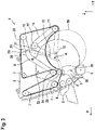
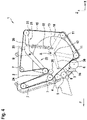
- FIG. 1 shows a sectional view of a round baler 1, more precisely of parts thereof, according to a first embodiment.
- various elements that are not the subject of the invention have been omitted. These include, in particular, wheels on which the round baler 1 stands, feed elements (such as a pick-up and a conveyor rotor) or a drawbar, by means of which the round baler 1 can be attached to a tractor. However, it could also be a self-propelled round baler 1 .
- a frame 2 can be seen, which ensures the structural stability and has a housing, which is not shown here.
- Essential parts of the frame 2 are side walls 3, each of which extends in the direction of a longitudinal axis X and in the direction of a vertical axis Z of the round baler 1.
- the longitudinal axis X pointing backwards is antiparallel to the direction of travel F.
- only one of the side walls 3 spaced apart along the transverse axis is visible in each case.
- Two press rollers 4, 5 can be seen in a front area, as well as a starter roller 6 further down and behind them.
- a plurality of frame guide rollers 7 can also be seen, over which an endless press element 15 is guided.
- the latter is formed by a plurality of press belts, which can be driven in a revolving manner by one or more frame guide rollers 7, which act as drive elements.
- the pressing element can also be formed by a single pressing belt, for example.
- the pressing element 15 is also guided over two flap guide rollers 11 of a tailgate 10 and over two rocker guide rollers 23 , 24 of a clamping rocker 20 .
- the tailgate 10 can be pivoted about a flap axis A relative to the frame.
- the flap guide rollers 11 are arranged at approximately the same distance from the axis A of the flap. Both flap guide rollers 11, like the frame guide rollers 7, rest on the inside of the pressing element 15.
- the clamping rocker 20 is arranged predominantly above the tailgate 10 with respect to the vertical axis Z and can be pivoted about a rocker axis B relative to the frame.
- a rear swingarm guide roller 23 is disposed on a rear swingarm portion 21 located rearward of the swingarm axis B with respect to the longitudinal axis X. As shown in FIG.
- Both the flap axis A and the rocker axis B run parallel to the transverse axis of the roller baler 1 and thus perpendicular to the plane of the figures.
- a single-acting first cylinder 30 acting as the first pressure element is connected to the side wall 3 via a frame pivot bearing 8 and to the tailgate 10 via a first flap pivot bearing 12.
- a second pressure element also single-acting cylinder 31, is connected via a second Flap pivot bearing 13 connected to the tailgate 10 and a swing pivot bearing 26 to the rear swing arm portion 21.
- Both cylinders 30, 31 are present as Formed hydraulic cylinders and can only exert a compressive force between their respective pivot bearings 8, 12, 13, 26.
- the guide rollers 7, 11, 23, 24 keep the pressing element 15 under tension.
- the press rollers 4, 5, the starter roller 6 and the pressing element 15 together define a press chamber 16 of variable size, in which a crop bale 50 is successively formed.
- the press chamber 16 is empty, the press element 15 is guided directly over an upper press roller 4 and the starter roller 6 .
- the tailgate 10 is lowered and thus closed.
- the first cylinder 30 can be depressurized and has assumed its minimum length, ie it is fully contracted.
- the clamping rocker 20 is in a position in which the rear rocker section 21 runs approximately horizontally or is slightly raised.
- the second cylinder 31 is extended, possibly to its maximum length, ie it is (possibly completely) expanded.
- tailgate 10 On the one hand, it exerts a force on tailgate 10, which presses it in the direction of the lowered position, and on the other hand, it exerts a force on rear rocker section 21 the front rocker guide roller 24 keeps the pressing member 15 under tension. If the force of the second cylinder 31 is not sufficient to keep the tailgate 10 in the lowered position, the tailgate 10 can also optionally be secured by a locking element, not shown here.
- the finished crop bale 50 is then ejected to the rear.
- the tailgate 10 is pivoted upwards by exerting a compressive force by means of the first cylinder 30, with the first cylinder 30 extending. Since the tensioning rocker 20 is coupled to the tailgate 10 via the fully contracted second cylinder 31, it is also forced to swing with the rear swing arm portion 21 moving upward and the front swing arm portion 22 moving downward. This prevents a collision between the tailgate 10 and the clamping rocker 20 and also maintains the tension in the pressing member 15.
- the tensioning rocker 20 swivels so far that the rear rocker section 21 passes over the in 1 position shown to the in 3 position shown.
- the front linkage portion 22 pivots downward and forward until the ejector roller 25 is pressed against a portion of the pressing member 15 that is in contact with the crop bale 50 .
- the ejector roller 25 thus exerts a proportionately rearwardly directed force on the crop bale 50 via the pressing element 15, as a result of which its ejection is triggered or at least supported.
- the tailgate 10 may not be able to pivot back down solely by its own weight or only with a delay, since the tension in the pressing element 15 can oppose this pivoting process.
- the pressure in the first cylinder 30 is reduced and on the other hand a compressive force is exerted via the second cylinder 31, by which the tailgate 10 is pressed downwards.
- the torque which acts on the clamping rocker 20 via the rocker guide rollers 23, 24 due to the tension in the pressing element 15, ensures that the clamping rocker 20 moves back into the in 1 position shown swings back.
- FIG. 4 shows a second embodiment of a round baler according to the invention, which largely corresponds to that in Figures 1 to 3 shown embodiment corresponds and is not explained again in this respect.
- a compression spring 32 is provided as the second pressure element.
- the clamping rocker 20 pivots as described above, with the compression spring 32 being compressed between the clamping rocker 20 and the tailgate 10 .
- a compressive force is again exerted via the first cylinder 30 and the first cylinder 30 expands, the clamping rocker 20 also being pivoted by power transmission via the tailgate 10 and the compression spring 32 .
Landscapes
- Life Sciences & Earth Sciences (AREA)
- Environmental Sciences (AREA)
- Harvester Elements (AREA)
- Harvesting Machines For Specific Crops (AREA)
Applications Claiming Priority (1)
| Application Number | Priority Date | Filing Date | Title |
|---|---|---|---|
| DE102021116199.1A DE102021116199A1 (de) | 2021-06-23 | 2021-06-23 | Rundballenpresse |
Publications (2)
| Publication Number | Publication Date |
|---|---|
| EP4108069A1 true EP4108069A1 (fr) | 2022-12-28 |
| EP4108069B1 EP4108069B1 (fr) | 2024-11-27 |
Family
ID=82020819
Family Applications (1)
| Application Number | Title | Priority Date | Filing Date |
|---|---|---|---|
| EP22178744.3A Active EP4108069B1 (fr) | 2021-06-23 | 2022-06-13 | Presse à balles rondes |
Country Status (5)
| Country | Link |
|---|---|
| US (1) | US12419224B2 (fr) |
| EP (1) | EP4108069B1 (fr) |
| DE (1) | DE102021116199A1 (fr) |
| DK (1) | DK4108069T3 (fr) |
| PL (1) | PL4108069T3 (fr) |
Cited By (2)
| Publication number | Priority date | Publication date | Assignee | Title |
|---|---|---|---|---|
| WO2024231910A3 (fr) * | 2023-05-08 | 2025-01-16 | McHale Engineering Unlimited Company | Presse à balles et procédé de mise en balles de matériau |
| US20250324926A1 (en) * | 2024-04-23 | 2025-10-23 | Cnh Industrial America Llc | Take-up, tensioning or serpentine arm with pivoting roll for agriculture baler |
Families Citing this family (4)
| Publication number | Priority date | Publication date | Assignee | Title |
|---|---|---|---|---|
| DE102023108947A1 (de) * | 2023-04-06 | 2024-10-10 | Maschinenfabrik Bernard Krone GmbH & Co. KG | Rundballenpresse |
| DE102023113954A1 (de) * | 2023-05-26 | 2024-11-28 | Maschinenfabrik Bernard Krone GmbH & Co. KG | Getriebeeinheit |
| DE102023117754A1 (de) * | 2023-07-05 | 2025-01-09 | Naturhof Schröder GmbH | Vorrichtung und Verfahren zur Herstellung eines Rundballens und Rundballen |
| US20250072333A1 (en) * | 2023-09-01 | 2025-03-06 | Cnh Industrial America Llc | Serpentine pivot roll |
Citations (3)
| Publication number | Priority date | Publication date | Assignee | Title |
|---|---|---|---|---|
| DE3941707A1 (de) * | 1989-12-18 | 1991-06-20 | Claas Ohg | Rundballenpresse fuer halmfoermiges erntegut |
| US20070081878A1 (en) * | 2001-03-22 | 2007-04-12 | Mchale Padraic C | Combined baler/bale wrapper |
| US20130298787A1 (en) * | 2012-05-09 | 2013-11-14 | Scott C. Simmons | Density system bypass for a round baler |
Family Cites Families (2)
| Publication number | Priority date | Publication date | Assignee | Title |
|---|---|---|---|---|
| NL2015525B1 (en) * | 2015-09-29 | 2017-04-20 | Forage Innovations Bv | Method and apparatus for forming round-cylindrical bales and depositing them on the ground at suitable locations. |
| CN105723958A (zh) * | 2016-04-22 | 2016-07-06 | 中外合资沃得重工(中国)有限公司 | 圆草捆打捆机成型圆草捆释放控制装置及控制方法 |
-
2021
- 2021-06-23 DE DE102021116199.1A patent/DE102021116199A1/de active Pending
-
2022
- 2022-06-13 DK DK22178744.3T patent/DK4108069T3/da active
- 2022-06-13 EP EP22178744.3A patent/EP4108069B1/fr active Active
- 2022-06-13 PL PL22178744.3T patent/PL4108069T3/pl unknown
- 2022-06-22 US US17/846,052 patent/US12419224B2/en active Active
Patent Citations (3)
| Publication number | Priority date | Publication date | Assignee | Title |
|---|---|---|---|---|
| DE3941707A1 (de) * | 1989-12-18 | 1991-06-20 | Claas Ohg | Rundballenpresse fuer halmfoermiges erntegut |
| US20070081878A1 (en) * | 2001-03-22 | 2007-04-12 | Mchale Padraic C | Combined baler/bale wrapper |
| US20130298787A1 (en) * | 2012-05-09 | 2013-11-14 | Scott C. Simmons | Density system bypass for a round baler |
Cited By (3)
| Publication number | Priority date | Publication date | Assignee | Title |
|---|---|---|---|---|
| WO2024231910A3 (fr) * | 2023-05-08 | 2025-01-16 | McHale Engineering Unlimited Company | Presse à balles et procédé de mise en balles de matériau |
| US20250324926A1 (en) * | 2024-04-23 | 2025-10-23 | Cnh Industrial America Llc | Take-up, tensioning or serpentine arm with pivoting roll for agriculture baler |
| EP4640037A1 (fr) * | 2024-04-23 | 2025-10-29 | CNH Industrial America LLC | Bras d'enroulement, de tension ou de serpentin avec rouleau pivotant pour ramasseuse-presse agricole |
Also Published As
| Publication number | Publication date |
|---|---|
| DE102021116199A1 (de) | 2022-12-29 |
| US20220408654A1 (en) | 2022-12-29 |
| EP4108069B1 (fr) | 2024-11-27 |
| DK4108069T3 (da) | 2025-03-03 |
| US12419224B2 (en) | 2025-09-23 |
| PL4108069T3 (pl) | 2025-04-14 |
Similar Documents
| Publication | Publication Date | Title |
|---|---|---|
| EP4108069B1 (fr) | Presse à balles rondes | |
| DE69707050T2 (de) | Ernteaufsammeleinrichtung | |
| DE69323738T2 (de) | Ballenpresszuführmechanismus | |
| EP2243349B1 (fr) | Presse à ballots ronds | |
| DE102006036199A1 (de) | Förderzusammenbau und Presse | |
| EP2484197A1 (fr) | Presse à balles rondes dotée de guidages latéraux pour courroies de presse | |
| EP3222134B1 (fr) | Roto-presse et procédé | |
| DE68905950T2 (de) | Ballenpresse. | |
| DE3443530A1 (de) | Ballenpresse | |
| DE2530249A1 (de) | Wickelballenpresse | |
| EP1790210A2 (fr) | Dispositif d'alimentation pour une faucheuse-hâcheuse | |
| EP1366654B1 (fr) | Presse à balles cylindriques | |
| DE102004002730A1 (de) | Ballenpresse | |
| DE10153517B4 (de) | Bindevorrichtung für eine Rundballenpresse | |
| EP3501261B1 (fr) | Moyen de guidage, presse à balles et procédé | |
| DE10145690A1 (de) | Ballenpresse | |
| EP0095689A1 (fr) | Presse à balles rondes dont la chambre de compactage comprend une entrée pour le matériau | |
| EP3569056B1 (fr) | Dispositif de guidage du moyen de pression et presse | |
| DE102007031211A1 (de) | Ballenpresse | |
| EP3959961B1 (fr) | Presse pour produits de récolte à tiges pourvu de module de coupe amovible et procédé de manipulation d'un tel module de coupe amovible | |
| DE10145691A1 (de) | Ballenpresse | |
| EP4183244A1 (fr) | Presse à balles rondes | |
| EP1595439B1 (fr) | Dispositif pour ramasser et compacter des matières récoltées | |
| EP3981245A1 (fr) | Presse agricole pour fourrage et procédé de dépôt des balles de fourrage comprimé | |
| DE10139450A1 (de) | Ballenpresse |
Legal Events
| Date | Code | Title | Description |
|---|---|---|---|
| PUAI | Public reference made under article 153(3) epc to a published international application that has entered the european phase |
Free format text: ORIGINAL CODE: 0009012 |
|
| STAA | Information on the status of an ep patent application or granted ep patent |
Free format text: STATUS: THE APPLICATION HAS BEEN PUBLISHED |
|
| AK | Designated contracting states |
Kind code of ref document: A1 Designated state(s): AL AT BE BG CH CY CZ DE DK EE ES FI FR GB GR HR HU IE IS IT LI LT LU LV MC MK MT NL NO PL PT RO RS SE SI SK SM TR |
|
| P01 | Opt-out of the competence of the unified patent court (upc) registered |
Effective date: 20230517 |
|
| STAA | Information on the status of an ep patent application or granted ep patent |
Free format text: STATUS: REQUEST FOR EXAMINATION WAS MADE |
|
| 17P | Request for examination filed |
Effective date: 20230628 |
|
| RBV | Designated contracting states (corrected) |
Designated state(s): AL AT BE BG CH CY CZ DE DK EE ES FI FR GB GR HR HU IE IS IT LI LT LU LV MC MK MT NL NO PL PT RO RS SE SI SK SM TR |
|
| GRAP | Despatch of communication of intention to grant a patent |
Free format text: ORIGINAL CODE: EPIDOSNIGR1 |
|
| STAA | Information on the status of an ep patent application or granted ep patent |
Free format text: STATUS: GRANT OF PATENT IS INTENDED |
|
| INTG | Intention to grant announced |
Effective date: 20240805 |
|
| RIC1 | Information provided on ipc code assigned before grant |
Ipc: A01F 15/08 20060101AFI20240726BHEP |
|
| GRAS | Grant fee paid |
Free format text: ORIGINAL CODE: EPIDOSNIGR3 |
|
| GRAA | (expected) grant |
Free format text: ORIGINAL CODE: 0009210 |
|
| STAA | Information on the status of an ep patent application or granted ep patent |
Free format text: STATUS: THE PATENT HAS BEEN GRANTED |
|
| AK | Designated contracting states |
Kind code of ref document: B1 Designated state(s): AL AT BE BG CH CY CZ DE DK EE ES FI FR GB GR HR HU IE IS IT LI LT LU LV MC MK MT NL NO PL PT RO RS SE SI SK SM TR |
|
| REG | Reference to a national code |
Ref country code: GB Ref legal event code: FG4D Free format text: NOT ENGLISH |
|
| REG | Reference to a national code |
Ref country code: CH Ref legal event code: EP |
|
| REG | Reference to a national code |
Ref country code: DE Ref legal event code: R096 Ref document number: 502022002212 Country of ref document: DE |
|
| REG | Reference to a national code |
Ref country code: IE Ref legal event code: FG4D Free format text: LANGUAGE OF EP DOCUMENT: GERMAN |
|
| REG | Reference to a national code |
Ref country code: NL Ref legal event code: FP |
|
| REG | Reference to a national code |
Ref country code: DK Ref legal event code: T3 Effective date: 20250225 |
|
| REG | Reference to a national code |
Ref country code: LT Ref legal event code: MG9D |
|
| PG25 | Lapsed in a contracting state [announced via postgrant information from national office to epo] |
Ref country code: HR Free format text: LAPSE BECAUSE OF FAILURE TO SUBMIT A TRANSLATION OF THE DESCRIPTION OR TO PAY THE FEE WITHIN THE PRESCRIBED TIME-LIMIT Effective date: 20241127 Ref country code: IS Free format text: LAPSE BECAUSE OF FAILURE TO SUBMIT A TRANSLATION OF THE DESCRIPTION OR TO PAY THE FEE WITHIN THE PRESCRIBED TIME-LIMIT Effective date: 20250327 Ref country code: PT Free format text: LAPSE BECAUSE OF FAILURE TO SUBMIT A TRANSLATION OF THE DESCRIPTION OR TO PAY THE FEE WITHIN THE PRESCRIBED TIME-LIMIT Effective date: 20250327 |
|
| PG25 | Lapsed in a contracting state [announced via postgrant information from national office to epo] |
Ref country code: FI Free format text: LAPSE BECAUSE OF FAILURE TO SUBMIT A TRANSLATION OF THE DESCRIPTION OR TO PAY THE FEE WITHIN THE PRESCRIBED TIME-LIMIT Effective date: 20241127 |
|
| PG25 | Lapsed in a contracting state [announced via postgrant information from national office to epo] |
Ref country code: BG Free format text: LAPSE BECAUSE OF FAILURE TO SUBMIT A TRANSLATION OF THE DESCRIPTION OR TO PAY THE FEE WITHIN THE PRESCRIBED TIME-LIMIT Effective date: 20241127 |
|
| PG25 | Lapsed in a contracting state [announced via postgrant information from national office to epo] |
Ref country code: ES Free format text: LAPSE BECAUSE OF FAILURE TO SUBMIT A TRANSLATION OF THE DESCRIPTION OR TO PAY THE FEE WITHIN THE PRESCRIBED TIME-LIMIT Effective date: 20241127 |
|
| PG25 | Lapsed in a contracting state [announced via postgrant information from national office to epo] |
Ref country code: NO Free format text: LAPSE BECAUSE OF FAILURE TO SUBMIT A TRANSLATION OF THE DESCRIPTION OR TO PAY THE FEE WITHIN THE PRESCRIBED TIME-LIMIT Effective date: 20250227 |
|
| PG25 | Lapsed in a contracting state [announced via postgrant information from national office to epo] |
Ref country code: GR Free format text: LAPSE BECAUSE OF FAILURE TO SUBMIT A TRANSLATION OF THE DESCRIPTION OR TO PAY THE FEE WITHIN THE PRESCRIBED TIME-LIMIT Effective date: 20250228 Ref country code: LV Free format text: LAPSE BECAUSE OF FAILURE TO SUBMIT A TRANSLATION OF THE DESCRIPTION OR TO PAY THE FEE WITHIN THE PRESCRIBED TIME-LIMIT Effective date: 20241127 |
|
| PG25 | Lapsed in a contracting state [announced via postgrant information from national office to epo] |
Ref country code: RS Free format text: LAPSE BECAUSE OF FAILURE TO SUBMIT A TRANSLATION OF THE DESCRIPTION OR TO PAY THE FEE WITHIN THE PRESCRIBED TIME-LIMIT Effective date: 20250227 |
|
| PG25 | Lapsed in a contracting state [announced via postgrant information from national office to epo] |
Ref country code: SM Free format text: LAPSE BECAUSE OF FAILURE TO SUBMIT A TRANSLATION OF THE DESCRIPTION OR TO PAY THE FEE WITHIN THE PRESCRIBED TIME-LIMIT Effective date: 20241127 |
|
| PGFP | Annual fee paid to national office [announced via postgrant information from national office to epo] |
Ref country code: DE Payment date: 20250618 Year of fee payment: 4 Ref country code: PL Payment date: 20250529 Year of fee payment: 4 |
|
| PGFP | Annual fee paid to national office [announced via postgrant information from national office to epo] |
Ref country code: DK Payment date: 20250618 Year of fee payment: 4 |
|
| PGFP | Annual fee paid to national office [announced via postgrant information from national office to epo] |
Ref country code: NL Payment date: 20250618 Year of fee payment: 4 Ref country code: BE Payment date: 20250617 Year of fee payment: 4 |
|
| PG25 | Lapsed in a contracting state [announced via postgrant information from national office to epo] |
Ref country code: EE Free format text: LAPSE BECAUSE OF FAILURE TO SUBMIT A TRANSLATION OF THE DESCRIPTION OR TO PAY THE FEE WITHIN THE PRESCRIBED TIME-LIMIT Effective date: 20241127 |
|
| PGFP | Annual fee paid to national office [announced via postgrant information from national office to epo] |
Ref country code: FR Payment date: 20250626 Year of fee payment: 4 |
|
| PG25 | Lapsed in a contracting state [announced via postgrant information from national office to epo] |
Ref country code: RO Free format text: LAPSE BECAUSE OF FAILURE TO SUBMIT A TRANSLATION OF THE DESCRIPTION OR TO PAY THE FEE WITHIN THE PRESCRIBED TIME-LIMIT Effective date: 20241127 |
|
| PGFP | Annual fee paid to national office [announced via postgrant information from national office to epo] |
Ref country code: AT Payment date: 20250721 Year of fee payment: 4 |
|
| PG25 | Lapsed in a contracting state [announced via postgrant information from national office to epo] |
Ref country code: SK Free format text: LAPSE BECAUSE OF FAILURE TO SUBMIT A TRANSLATION OF THE DESCRIPTION OR TO PAY THE FEE WITHIN THE PRESCRIBED TIME-LIMIT Effective date: 20241127 |
|
| PG25 | Lapsed in a contracting state [announced via postgrant information from national office to epo] |
Ref country code: CZ Free format text: LAPSE BECAUSE OF FAILURE TO SUBMIT A TRANSLATION OF THE DESCRIPTION OR TO PAY THE FEE WITHIN THE PRESCRIBED TIME-LIMIT Effective date: 20241127 |
|
| PG25 | Lapsed in a contracting state [announced via postgrant information from national office to epo] |
Ref country code: IT Free format text: LAPSE BECAUSE OF FAILURE TO SUBMIT A TRANSLATION OF THE DESCRIPTION OR TO PAY THE FEE WITHIN THE PRESCRIBED TIME-LIMIT Effective date: 20241127 |
|
| PGFP | Annual fee paid to national office [announced via postgrant information from national office to epo] |
Ref country code: IE Payment date: 20250618 Year of fee payment: 4 |
|
| REG | Reference to a national code |
Ref country code: DE Ref legal event code: R097 Ref document number: 502022002212 Country of ref document: DE |
|
| PG25 | Lapsed in a contracting state [announced via postgrant information from national office to epo] |
Ref country code: SE Free format text: LAPSE BECAUSE OF FAILURE TO SUBMIT A TRANSLATION OF THE DESCRIPTION OR TO PAY THE FEE WITHIN THE PRESCRIBED TIME-LIMIT Effective date: 20241127 |
|
| PLBE | No opposition filed within time limit |
Free format text: ORIGINAL CODE: 0009261 |
|
| STAA | Information on the status of an ep patent application or granted ep patent |
Free format text: STATUS: NO OPPOSITION FILED WITHIN TIME LIMIT |
|
| REG | Reference to a national code |
Ref country code: CH Ref legal event code: L10 Free format text: ST27 STATUS EVENT CODE: U-0-0-L10-L00 (AS PROVIDED BY THE NATIONAL OFFICE) Effective date: 20251008 |
|
| 26N | No opposition filed |
Effective date: 20250828 |
|
| REG | Reference to a national code |
Ref country code: CH Ref legal event code: H13 Free format text: ST27 STATUS EVENT CODE: U-0-0-H10-H13 (AS PROVIDED BY THE NATIONAL OFFICE) Effective date: 20260127 |
|
| PG25 | Lapsed in a contracting state [announced via postgrant information from national office to epo] |
Ref country code: MC Free format text: LAPSE BECAUSE OF FAILURE TO SUBMIT A TRANSLATION OF THE DESCRIPTION OR TO PAY THE FEE WITHIN THE PRESCRIBED TIME-LIMIT Effective date: 20241127 |
|
| PG25 | Lapsed in a contracting state [announced via postgrant information from national office to epo] |
Ref country code: LU Free format text: LAPSE BECAUSE OF NON-PAYMENT OF DUE FEES Effective date: 20250613 |
|
| PG25 | Lapsed in a contracting state [announced via postgrant information from national office to epo] |
Ref country code: CH Free format text: LAPSE BECAUSE OF NON-PAYMENT OF DUE FEES Effective date: 20250630 |